EP1617952B2 - A driving device for a centrifugal separator - Google Patents
A driving device for a centrifugal separator Download PDFInfo
- Publication number
- EP1617952B2 EP1617952B2 EP04724918A EP04724918A EP1617952B2 EP 1617952 B2 EP1617952 B2 EP 1617952B2 EP 04724918 A EP04724918 A EP 04724918A EP 04724918 A EP04724918 A EP 04724918A EP 1617952 B2 EP1617952 B2 EP 1617952B2
- Authority
- EP
- European Patent Office
- Prior art keywords
- spindle
- rotor
- bearing
- driving device
- frame
- Prior art date
- Legal status (The legal status is an assumption and is not a legal conclusion. Google has not performed a legal analysis and makes no representation as to the accuracy of the status listed.)
- Expired - Lifetime
Links
- 239000003595 mist Substances 0.000 claims description 20
- 230000033001 locomotion Effects 0.000 claims description 13
- 238000005461 lubrication Methods 0.000 claims description 6
- 230000001050 lubricating effect Effects 0.000 claims description 5
- 239000002826 coolant Substances 0.000 claims description 2
- 239000003921 oil Substances 0.000 description 31
- 239000000725 suspension Substances 0.000 description 5
- 239000012809 cooling fluid Substances 0.000 description 4
- 238000005192 partition Methods 0.000 description 4
- 238000005452 bending Methods 0.000 description 3
- 239000010687 lubricating oil Substances 0.000 description 3
- 238000004519 manufacturing process Methods 0.000 description 2
- 230000010355 oscillation Effects 0.000 description 2
- 230000003534 oscillatory effect Effects 0.000 description 2
- 238000010276 construction Methods 0.000 description 1
- 238000001816 cooling Methods 0.000 description 1
- 238000006073 displacement reaction Methods 0.000 description 1
- 230000005484 gravity Effects 0.000 description 1
- 239000002184 metal Substances 0.000 description 1
- 239000002245 particle Substances 0.000 description 1
- 238000000926 separation method Methods 0.000 description 1
- 239000007787 solid Substances 0.000 description 1
- XLYOFNOQVPJJNP-UHFFFAOYSA-N water Substances O XLYOFNOQVPJJNP-UHFFFAOYSA-N 0.000 description 1
Images

Classifications
-
- F—MECHANICAL ENGINEERING; LIGHTING; HEATING; WEAPONS; BLASTING
- F16—ENGINEERING ELEMENTS AND UNITS; GENERAL MEASURES FOR PRODUCING AND MAINTAINING EFFECTIVE FUNCTIONING OF MACHINES OR INSTALLATIONS; THERMAL INSULATION IN GENERAL
- F16C—SHAFTS; FLEXIBLE SHAFTS; ELEMENTS OR CRANKSHAFT MECHANISMS; ROTARY BODIES OTHER THAN GEARING ELEMENTS; BEARINGS
- F16C27/00—Elastic or yielding bearings or bearing supports, for exclusively rotary movement
- F16C27/06—Elastic or yielding bearings or bearing supports, for exclusively rotary movement by means of parts of rubber or like materials
- F16C27/066—Ball or roller bearings
-
- B—PERFORMING OPERATIONS; TRANSPORTING
- B04—CENTRIFUGAL APPARATUS OR MACHINES FOR CARRYING-OUT PHYSICAL OR CHEMICAL PROCESSES
- B04B—CENTRIFUGES
- B04B9/00—Drives specially designed for centrifuges; Arrangement or disposition of transmission gearing; Suspending or balancing rotary bowls
- B04B9/02—Electric motor drives
- B04B9/04—Direct drive
-
- B—PERFORMING OPERATIONS; TRANSPORTING
- B04—CENTRIFUGAL APPARATUS OR MACHINES FOR CARRYING-OUT PHYSICAL OR CHEMICAL PROCESSES
- B04B—CENTRIFUGES
- B04B9/00—Drives specially designed for centrifuges; Arrangement or disposition of transmission gearing; Suspending or balancing rotary bowls
- B04B9/12—Suspending rotary bowls ; Bearings; Packings for bearings
-
- F—MECHANICAL ENGINEERING; LIGHTING; HEATING; WEAPONS; BLASTING
- F16—ENGINEERING ELEMENTS AND UNITS; GENERAL MEASURES FOR PRODUCING AND MAINTAINING EFFECTIVE FUNCTIONING OF MACHINES OR INSTALLATIONS; THERMAL INSULATION IN GENERAL
- F16C—SHAFTS; FLEXIBLE SHAFTS; ELEMENTS OR CRANKSHAFT MECHANISMS; ROTARY BODIES OTHER THAN GEARING ELEMENTS; BEARINGS
- F16C33/00—Parts of bearings; Special methods for making bearings or parts thereof
- F16C33/30—Parts of ball or roller bearings
- F16C33/66—Special parts or details in view of lubrication
- F16C33/6637—Special parts or details in view of lubrication with liquid lubricant
- F16C33/6659—Details of supply of the liquid to the bearing, e.g. passages or nozzles
- F16C33/6662—Details of supply of the liquid to the bearing, e.g. passages or nozzles the liquid being carried by air or other gases, e.g. mist lubrication
-
- H—ELECTRICITY
- H02—GENERATION; CONVERSION OR DISTRIBUTION OF ELECTRIC POWER
- H02K—DYNAMO-ELECTRIC MACHINES
- H02K5/00—Casings; Enclosures; Supports
- H02K5/04—Casings or enclosures characterised by the shape, form or construction thereof
- H02K5/16—Means for supporting bearings, e.g. insulating supports or means for fitting bearings in the bearing-shields
- H02K5/173—Means for supporting bearings, e.g. insulating supports or means for fitting bearings in the bearing-shields using bearings with rolling contact, e.g. ball bearings
- H02K5/1732—Means for supporting bearings, e.g. insulating supports or means for fitting bearings in the bearing-shields using bearings with rolling contact, e.g. ball bearings radially supporting the rotary shaft at both ends of the rotor
-
- F—MECHANICAL ENGINEERING; LIGHTING; HEATING; WEAPONS; BLASTING
- F16—ENGINEERING ELEMENTS AND UNITS; GENERAL MEASURES FOR PRODUCING AND MAINTAINING EFFECTIVE FUNCTIONING OF MACHINES OR INSTALLATIONS; THERMAL INSULATION IN GENERAL
- F16C—SHAFTS; FLEXIBLE SHAFTS; ELEMENTS OR CRANKSHAFT MECHANISMS; ROTARY BODIES OTHER THAN GEARING ELEMENTS; BEARINGS
- F16C2320/00—Apparatus used in separating or mixing
- F16C2320/42—Centrifuges
Definitions
- the present invention relates to a driving device for a centrifugal separator, more closely a centrifugal separator comprising
- centrifugal separator of this kind is described in DE 37 14 627 .
- the centrifugal rotor in this case is supported at the top of the vertical spindle, and the driving device comprises an electric standard type motor, which may be arranged in two different ways.
- the electric motor is situated below said second bearing, as shown in the drawing.
- the electric standard type motor would be arranged between said two bearings.
- An arrangement according to the last-mentioned alternative would have the advantage that the whole centrifugal separator became more compact.
- said second (lower) bearing is radially immovable in relation to the frame, whereas said first (upper) bearing may move somewhat radially, for one thing, so that the spindle may adapt itself to changes of position of the centre of gravity of the centrifugal rotor, which occur during operation of the centrifugal rotor. Such changes of position always occur to a larger or smaller extent and are caused by unbalance of the centrifugal rotor. Thus, the spindle will always perform oscillatory motions.
- the object of the present invention is to provide a driving device for a centrifugal separator of the above defined kind, which driving device does not cause the bearings and the housing being subjected to unacceptably heavy loads but, despite this, makes possible a compact construction for the whole centrifugal separator.
- this object may be obtained by means of a driving device of the initially defined kind, which is characterized in that the stator of the motor is fixed to the frame in a way such that it is radially immovable relative to the same, whereas the rotor of the motor is radially movable relative to the stator of the motor together with the spindle, a gap between the rotor and the stator of the motor being dimensioned to permit the radial movability of the rotor of the motor, and the first bearing is arranged to take up substantially all axial forces to be transferred between the spindle and the frame.
- the invention may, if desired, be used in a centrifugal separator, wherein the spindle is suspended in a frame and the centrifugal rotor is supported at the lower end of the spindle, but in a preferred embodiment of the invention the centrifugal rotor is supported at the upper end of the spindle.
- a preferred embodiment of the driving device according to the invention is characterized in that the lubricating device comprises a generating member to generate an oil mist in an oil chamber, that the first bearing and the second bearing are arranged in a first bearing chamber and a second bearing chamber, respectively, said bearing chambers communicating through oil passages with said oil chamber, and that said gap between the rotor and the stator of the motor forms a substantial part of a flow path for oil axially through the motor.
- the oil used for lubrication of the bearings also may be used for continuous cooling of the electric motor upon passage through said gap between the rotor and the stator of the motor.
- a fan device being connected to the spindle is arranged to transport oil mist in a circuit comprising said gap in the motor.
- the fan device may be arranged between said first bearing chamber and an intermediate chamber communicating with the gap, the fan device being arranged to transport oil mist in one of the directions between said first bearing chamber and the intermediate chamber.
- said circuit comprises in addition to the gap in the motor at least one further passage connecting said bearing chambers with each other.
- the passage may be provided in an inexpensive and simple way by being created between the outside of the frame and a member connected to the frame.
- the passage preferably comprises several channels evenly distributed around the spindle and delimited between the frame and said member.
- the frame preferably is surrounded by a jacket delimiting a space for through flow of a cooling medium in heat transferring contact with the frame.
- said jacket is double-walled, the inner one of the jacket walls delimiting together with the frame said channels for oil mist.
- the spindle In a centrifugal separator of the kind here in question the spindle is often dimensioned so that it can be permitted to bend somewhat, even if insignificantly, during rotation of the centrifugal rotor. Such bending may cause problem in an arrangement according to the invention, if the rotor of the electric motor is not as flexible as the spindle.
- the rotor of the motor may be composed of stacked ring-shaped discs permanently connected to each other to a very stiff cylindrical body. Even a slight displacement of these ring-shaped discs relative to each other during the manufacture of the cylindrical body may result in the openings at the ends of the body not being placed exactly coaxially.
- the rotor of the motor at its one end is connected with the spindle in such a way that, in this area, it is radially immovable relative the spindle but for the rest is free to move somewhat radially relative to the spindle, so that the relatively flexible spindle is not unnecessarily loaded by the relatively stiff rotor.
- the rotor is damaged upon bending of the spindle during rotation of the centrifugal rotor.
- the rotor may comprise a first part in the form of a substantially cylindrical sleeve and a second part surrounding the sleeve and connected to its outside.
- Said second part of the rotor may be constituted by a body comprising ring-shaped discs of the kind earlier described.
- the rotor is suitably arranged so that a heat-insulating gap is formed between the rotor and the spindle at least along a part of the rotor of the motor.
- a gap can serve its purpose even if it is very thin, e.g. 1 mm.
- a driving device may with advantage be used in a centrifugal separator, wherein the centrifugal rotor is supported at the upper end of the spindle and the frame surrounds a space, in which the electric motor and a part of the spindle and also said two bearings are arranged.
- the frame may be formed such, namely, that said space is completely closed from connection with the surrounding atmosphere below said first bearing.
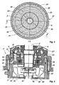
- Fig. 1 shows an axial section of a driving device for rotation of a centrifugal rotor
- Fig. 2 shows a cross section through the driving device along the line II - II in Fig. 1
- Fig. 3 shows a part of the driving device in a larger scale.
- Figure 1 shows a part of a centrifugal rotor 1 and a driving device 2 for rotation of the centrifugal rotor around a vertical rotational axis R.
- the centrifugal rotor 1 is connected to the driving device 2 by means of a spindle 3.
- the driving device 2 comprises a frame, the main part of which consists of a substantially cylindrical housing 4. This housing supports said spindle 3 via a lower bearing 5 and an upper bearing 6.
- the lower bearing 5 is supported by a bearing support member 7, which is connected with a bottom plate 8.
- the bottom plate 8 in turn is connected to the housing 4.
- the upper bearing 6 is supported by the upper part of the housing in a way that is described later.
- the upper part of the housing is covered by a cap 9.
- a partition 10 is located, which between itself and the cap 9 delimits an upper chamber 11 in the upper part of the housing 4.
- the upper bearing 6 is situated within the upper chamber 11.
- the upper bearing 6 is an angular contact ball bearing, which is dimensioned for transferring substantially all axial forces generated between the spindle 3 and the housing 4.
- the lower bearing 5, also a ball bearing, is dimensioned for transferring substantially only radial forces and is formed to permit some inclination of the spindle 3 in relation to a vertical line.
- An electric motor 12 is arranged between the partition 10 and the bottom plate 8.
- An intermediate chamber 13 is delimited between the partition 10 and the motor 12.
- the motor 12 comprises a stator 14 and a rotor 15.
- the stator is rigidly connected to the housing 4, whereas the rotor 15 is connected to the spindle and thus rotatable together with the same.
- a gap 16 is formed, connecting the intermediate chamber 13 with a lower chamber 17 formed between the motor 12 and the bottom plate 8.
- the gap 16 permits a radial movement of the spindle 3 and the rotor 15 relative to the stator 14 and the housing 4.
- the rotor 15 comprises two main parts, a sleeve 18 and a rotor package 19.
- the rotor package 19 consists of moulded ring-shaped metal discs which, stacked onto each other, surround and are rigidly connected to each other and to the sleeve 18.
- the sleeve 18 in turn, at its upper end, is connected to the spindle 3 in a way described in more detail below and more clearly shown in figure 3 .
- the aforementioned bearing support member 7 supports the lower bearing 5.
- the bearing support member 7 delimits an oil chamber 21, which like the lower chamber 17 is partly filled with lubricating oil.
- the upper free surface of the oil is indicated by a small triangle.
- the oil chamber 21 communicates with the lower chamber 17 both below the oil surface of the oil through holes 22 and above the oil surface through holes 23 and 24.
- the spindle 3 supports an oil mist generating member 25.
- the upper bearing 6 is supported by the housing 4 by means of a resilient suspension device comprising both lower and upper rubber bushings 26 and 27, respectively, and a lower and an upper ring-shaped member 28 and 29, respectively.
- the lower rubber bushings 26, distributed around the rotational axis R, are arranged between the lower ring-shaped member 28 and the partition 10.
- the upper rubber bushings 27, also distributed around the rotational axis R, are arranged between the upper ring-shaped member 29 and the cap 9.
- the ring-shaped members 28, 29 are arranged between the bearing 6 and respective bushings 26, 27.
- screw springs 30 are arranged to make the entire suspension device somewhat stiffer.
- the purpose of the suspension device is to counteract by spring force, in an area axially between the electric motor 12 and the centrifugal rotor 1, a radial movement of the spindle 3 relative to the housing 4.
- the housing 4 is surrounded by a jacket 32.
- the jacket has an inner wall 33 and an outer wall 34. Between the walls 33, 34 a space 35 is formed where a cooling fluid, e.g. water, may flow.
- the cooling fluid in this way may cool the housing 4, which is heated substantially by the electric motor during operation of the centrifugal rotor.
- each channels 36 communicates at its lower end with the lower chamber 17 through an opening 37, and communicates at its upper end with the upper chamber 11 through an opening 38.
- the spindle 3 supports a fan device 39.
- This comprises a fan wheel with a number of wings or blades distributed around the spindle and extending outwards from it.
- the fan device has its suction side in communication with the upper chamber 11 through a central annular passage 40 and its pressure side in communication with the intermediate chamber 13.
- the fan device may be turned in a way having its suction side in communication with the intermediate chamber 13 and its pressure side in communication with the upper chamber 11.
- the electric motor 12 is connected for its operation to a control unit 41.
- This in turn is connected to a source of current (not shown) and contains control equipment of some suitable kind for driving of, among other things, the motor 12.
- Cables 42 extend between the control unit 41 and the stator 14 of the motor through a pipe 43 and an opening 44 in the housing 4.
- the pipe 43 at its connection to the control unit 41 is provided with a cover or the like, which fills or covers the interior of the pipe but through which the cables 42 extend.
- Figure 3 shows a part of the driving device according to the invention in a larger scale. Moreover, figure 3 illustrates how the aforementioned sleeve 18 at its upper end is connected with the spindle 3.
- the sleeve 18 has an enlarged portion 45 at its upper end.
- This portion 45 has at least one axial slit 46 extending from the upper end of the sleeve 18 and a distance downwards.
- a screw 47, bridging the slit 46, is arranged to squeeze the portion 45 of the sleeve 18 firmly to the spindle 3.
- the above described driving device operates as follows upon rotation of the centrifugal rotor.
- the spindle 3 and thereby also the centrifugal rotor 1 is brought into rotation around the rotational axis R.
- the oil mist generating member 25 thereby is brought to rotate in the lubricating oil present in the oil chamber 21, so that a part of the lubricating oil is transformed into oil mist.
- the oil mist passes through the holes 23, 24 and fills the lower chamber 17. This results in an effective lubrication of the lower bearing 5, the interior of which communicates with the upper part of the chamber 17.
- the fan device 39 By the rotation of the spindle also the fan device 39 is brought into rotation. This generates a certain overpressure in the intermediate chamber 13 and a certain underpressure in the upper chamber 11.
- transportation of oil mist is accomplished from the lower chamber 17, through the openings 37, the channels 36 and the openings 38, to the upper chamber 11.
- the oil mist is conducted through at least the channels 31 to the interior of the bearing 6 and further through the central passage 40 to the suction side of the fan device 39. This results in an effective lubrication of the upper bearing 6.
- Air and possibly remaining oil mist is forced from the intermediate chamber 13 through the gap 16 of the motor back to the lower chamber 17. Also oil deposited on surfaces inside the housing 4 runs back to the oil bath in the lower chamber 17.
- unbalance may arise, e.g. as a result of separated solid particles being unevenly distributed in the separation chamber of the centrifugal rotor.
- Such unbalance may result in the spindle 3 being subjected to bending and/or the spindle 3 being caused to perform a rotational movement around and at distance from a new rotational axis of the centrifugal rotor.
- Such movements of the spindle 3, or a part of the same are permitted thanks to the previously described spring suspension of the upper bearing 6.
- the gap 16 between the stator 14 and the rotor 15 of the electric motor is so wide, that also this permits such movements.
- the gap 20 between the spindle 3 and the rotor 15 is dimensioned in a way so that the spindle 3 may be bended somewhat without getting into contact with the rotor 15 below the connection between the spindle 3 and the sleeve 18.
- the gap 16 between the stator 14 and the rotor 15 of the motor has an important purpose to serve also by forming a transport path for the oil mist being transported in a circuit by means of the fan device 39.
- the oil mist in addition to lubricate and cool the bearings 5 and 6 the oil mist also will cool the motor 12 itself, both its rotor and its stator.
- the oil mist continually takes away heat from the motor during its transport through the gap 16 and delivers this heat during its passage through the channels 36 to the cooling fluid flowing through the jacket 32.
- the cooling fluid simultaneously cools the outside of the stator of the motor being in contact with the inside of the housing 4.
- the fan device 39 alternatively may be arranged so that oil mist circulates in the reverse direction in the circuit described above, i.e. upwards through the gap 16 and downwards through the channels 36 on the outside of the frame.
Applications Claiming Priority (2)
| Application Number | Priority Date | Filing Date | Title |
|---|---|---|---|
| SE0301029A SE526010C2 (sv) | 2003-04-08 | 2003-04-08 | En drivanordning för en centrifugalseparator |
| PCT/SE2004/000492 WO2004089550A1 (en) | 2003-04-08 | 2004-03-31 | A driving device for a centrifugal separator |
Publications (3)
| Publication Number | Publication Date |
|---|---|
| EP1617952A1 EP1617952A1 (en) | 2006-01-25 |
| EP1617952B1 EP1617952B1 (en) | 2009-11-11 |
| EP1617952B2 true EP1617952B2 (en) | 2012-12-26 |
Family
ID=20290965
Family Applications (1)
| Application Number | Title | Priority Date | Filing Date |
|---|---|---|---|
| EP04724918A Expired - Lifetime EP1617952B2 (en) | 2003-04-08 | 2004-03-31 | A driving device for a centrifugal separator |
Country Status (9)
| Country | Link |
|---|---|
| US (1) | US7300396B2 (sv) |
| EP (1) | EP1617952B2 (sv) |
| JP (1) | JP2006522679A (sv) |
| CN (1) | CN100400170C (sv) |
| AT (1) | ATE448025T1 (sv) |
| DE (1) | DE602004024051D1 (sv) |
| RU (1) | RU2005134363A (sv) |
| SE (1) | SE526010C2 (sv) |
| WO (1) | WO2004089550A1 (sv) |
Cited By (3)
| Publication number | Priority date | Publication date | Assignee | Title |
|---|---|---|---|---|
| DE102013105006A1 (de) | 2012-05-22 | 2013-11-28 | Gea Mechanical Equipment Gmbh | Antriebsvorrichtung für eine Separatoranordnung |
| US9981275B2 (en) | 2012-11-12 | 2018-05-29 | Gea Mechanical Equipment Gmbh | Separator with direct drive and coolant system integrated into drive housing |
| DE102017114649A1 (de) * | 2017-06-30 | 2019-01-03 | Gea Mechanical Equipment Gmbh | Separator mit Direktantrieb |
Families Citing this family (16)
| Publication number | Priority date | Publication date | Assignee | Title |
|---|---|---|---|---|
| SE526010C2 (sv) * | 2003-04-08 | 2005-06-14 | Alfa Laval Corp Ab | En drivanordning för en centrifugalseparator |
| US7011618B2 (en) * | 2003-05-16 | 2006-03-14 | Kendro Laboratory Products Lp | Attachment and release apparatus for a centrifuge rotor cover |
| DE102006020467A1 (de) * | 2006-04-28 | 2007-10-31 | Westfalia Separator Ag | Separator mit Direktantrieb |
| SE530223C2 (sv) * | 2006-05-15 | 2008-04-01 | Alfa Laval Corp Ab | Centrifugalseparator |
| DE102007060588A1 (de) * | 2007-12-13 | 2009-06-18 | Gea Westfalia Separator Gmbh | Separator mit einem Direktantrieb |
| US8758209B2 (en) * | 2007-12-13 | 2014-06-24 | Gea Mechanical Equipment Gmbh | Separator having a lubrication system for a short spindle drive |
| TWI593462B (zh) * | 2007-12-21 | 2017-08-01 | 阿法瓦塞爾曼股份有限公司 | 連續流超離心系統(二) |
| SE533276C2 (sv) | 2008-12-19 | 2010-08-10 | Alfa Laval Corp Ab | Centrifugalseparator med smörjanordning |
| DE102009009958A1 (de) * | 2009-02-23 | 2010-09-02 | Hanning Elektro-Werke Gmbh & Co. Kg | Zentrifuge |
| CN104619539B (zh) | 2012-09-28 | 2017-06-23 | 爱信艾达株式会社 | 混合动力驱动装置 |
| EP3227575B1 (fr) | 2014-12-04 | 2021-01-13 | Bobst Mex Sa | Palier, groupe de transformation d'un support plan, et procedes de montage et demontage d'un outil rotatif |
| US11654385B2 (en) | 2015-09-24 | 2023-05-23 | Cummins Filtration Ip, Inc | Utilizing a mechanical seal between a filter media and an endcap of a rotating filter cartridge |
| DE102017200399A1 (de) * | 2017-01-12 | 2018-07-12 | Zf Friedrichshafen Ag | Lamellenbremse |
| US11446598B2 (en) | 2017-06-20 | 2022-09-20 | Cummins Filtration Ip, Inc. | Axial flow centrifugal separator |
| US10695774B2 (en) * | 2017-11-21 | 2020-06-30 | Richard F Corbus | Centrifuge separator for gold mining and recovery |
| DE102020111217A1 (de) | 2020-04-24 | 2021-10-28 | Gea Mechanical Equipment Gmbh | Separator mit Direktantrieb |
Citations (11)
| Publication number | Priority date | Publication date | Assignee | Title |
|---|---|---|---|---|
| DE513192C (de) † | 1930-11-24 | Ramesohl & Schmidt Akt Ges | Unterteilte Schleuderspindel | |
| GB368247A (en) † | 1929-08-31 | 1932-03-03 | Gen Electric | Improvements in and relating to methods of mounting high speed shafts |
| US2487343A (en) † | 1948-04-23 | 1949-11-08 | Laval Separator Co De | Bearing assembly for centrifuges and the like |
| US2913169A (en) † | 1955-09-19 | 1959-11-17 | Westfalia Separator Ag | Centrifuge drive arrangement |
| FR1287551A (fr) † | 1961-02-02 | 1962-03-16 | Garin Ets | Appareil tel qu'écrémeuse |
| DE2108590A1 (de) † | 1971-02-23 | 1972-09-07 | Siemens Ag | Anordnung zur Lagerung einer hochtourig, insbesondere elektromotorisch angetriebenen Welle |
| DE2854566A1 (de) † | 1978-12-18 | 1980-06-19 | Beckman Instruments Gmbh | Schwingungsdaempfende lagerungs-anordnung einer rotierenden spindel |
| EP0290606A1 (de) † | 1986-11-20 | 1988-11-17 | Moskovskoe Nauchno-Proizvodstvennoe Obiedinenie 'biofizpribor' | Zentrifuge |
| JPH0416254A (ja) † | 1990-05-10 | 1992-01-21 | Nippon Pillar Packing Co Ltd | 高速駆動機構の潤滑冷却装置 |
| JPH0531402A (ja) † | 1991-07-31 | 1993-02-09 | Hitachi Koki Co Ltd | 遠心機駆動装置のオイル供給装置 |
| DE4209625A1 (de) † | 1992-03-25 | 1993-09-30 | Isad Ingenieurbuero Gmbh Fuer | Rotorsystem |
Family Cites Families (25)
| Publication number | Priority date | Publication date | Assignee | Title |
|---|---|---|---|---|
| SE505128C2 (sv) * | 1995-10-10 | 1997-06-30 | Alfa Laval Ab | Dämpningsanordning |
| US2556317A (en) * | 1948-04-06 | 1951-06-12 | Laval Separator Co De | Bearing assembly for centrifuges and the like |
| US2534738A (en) * | 1948-06-18 | 1950-12-19 | Laval Separator Co De | Mount for rotating parts |
| US2698131A (en) * | 1951-12-26 | 1954-12-28 | Laval Separator Co De | Centrifugal separator |
| US2916201A (en) * | 1956-02-21 | 1959-12-08 | Westfalia Separator Ag | Centrifuge drive spindle arrangement |
| DE2122464C3 (de) * | 1971-05-06 | 1978-10-26 | Heraeus-Christ Gmbh, 3360 Osterode | Lageranordnung für eine Ultrazentrifuge |
| FR2495711A1 (fr) * | 1980-12-05 | 1982-06-11 | Robatel Slpi | Dispositif de palier pour centrifugeuse |
| US4412707A (en) * | 1981-12-30 | 1983-11-01 | Robatel Slpi | Bearing device for centrifuge |
| SE445665B (sv) * | 1984-11-28 | 1986-07-07 | Alfa Laval Separation Ab | Centrifugalseparator med ett holje avtetat medelst en mekanisk tetning |
| US4846773A (en) * | 1985-05-13 | 1989-07-11 | Beckman Instruments, Inc. | Rotating system critical speed whirl damper |
| SE8504132D0 (sv) * | 1985-09-05 | 1985-09-05 | Alfa Laval Separation Ab | Lagersmorjningsanordning vid en centrifugalseparator |
| DD248968A1 (de) * | 1986-05-14 | 1987-08-26 | Kyffhaeuserhuette Maschf | Leistungselektronischer antrieb fuer zentrifugalseparatoren |
| SU1704839A1 (ru) * | 1988-07-18 | 1992-01-15 | Московское научно-производственное объединение "Биофизприбор" | Привод ультрацентрифуги |
| DE4314440C1 (de) * | 1993-05-03 | 1994-06-16 | Kyffhaeuser Maschf Artern Gmbh | Zentrifugalseparator mit Schwerstanlauf |
| SE517176C2 (sv) * | 1997-06-11 | 2002-04-23 | Alfa Laval Ab | Stödanordning för en centrifugalseparator |
| SE510204C2 (sv) * | 1997-06-16 | 1999-05-03 | Alfa Laval Ab | Anordning och sätt för kylning av ett lager |
| SE9702290D0 (sv) * | 1997-06-16 | 1997-06-16 | Alfa Laval Ab | Tätningsanordning för en centrifugalseparator |
| SE509516C2 (sv) * | 1997-06-16 | 1999-02-08 | Alfa Laval Ab | Anordning för att tillföra en vätska vid ett lager till en roterande axel |
| SE512770C2 (sv) | 1998-02-19 | 2000-05-08 | Alfa Laval Ab | Stödanordning |
| SE513789C2 (sv) * | 1999-03-08 | 2000-11-06 | Alfa Laval Ab | Drivenhet för en centrifugrotor hos en centrifugalseparator |
| US6354988B1 (en) * | 1999-06-17 | 2002-03-12 | Kendro Laboratory Products, Llp | Centrifuge gyro diaphragm capable of maintaining motor shaft concentricity |
| DE10125808A1 (de) * | 2001-05-26 | 2002-12-12 | Westfalia Separator Food Tec G | Zentrifugalseparator |
| DE10212808B4 (de) * | 2002-03-22 | 2004-07-29 | Westfalia Separator Ag | Separator |
| DE10314118B4 (de) * | 2003-03-28 | 2005-05-12 | Westfalia Separator Ag | Antriebsvorrichtung für einen Separator |
| SE526010C2 (sv) * | 2003-04-08 | 2005-06-14 | Alfa Laval Corp Ab | En drivanordning för en centrifugalseparator |
-
2003
- 2003-04-08 SE SE0301029A patent/SE526010C2/sv not_active IP Right Cessation
-
2004
- 2004-03-31 US US10/551,161 patent/US7300396B2/en not_active Expired - Lifetime
- 2004-03-31 EP EP04724918A patent/EP1617952B2/en not_active Expired - Lifetime
- 2004-03-31 WO PCT/SE2004/000492 patent/WO2004089550A1/en active Application Filing
- 2004-03-31 AT AT04724918T patent/ATE448025T1/de not_active IP Right Cessation
- 2004-03-31 RU RU2005134363/12A patent/RU2005134363A/ru not_active Application Discontinuation
- 2004-03-31 DE DE602004024051T patent/DE602004024051D1/de not_active Expired - Lifetime
- 2004-03-31 CN CNB2004800090426A patent/CN100400170C/zh not_active Expired - Lifetime
- 2004-03-31 JP JP2006507993A patent/JP2006522679A/ja active Pending
Patent Citations (11)
| Publication number | Priority date | Publication date | Assignee | Title |
|---|---|---|---|---|
| DE513192C (de) † | 1930-11-24 | Ramesohl & Schmidt Akt Ges | Unterteilte Schleuderspindel | |
| GB368247A (en) † | 1929-08-31 | 1932-03-03 | Gen Electric | Improvements in and relating to methods of mounting high speed shafts |
| US2487343A (en) † | 1948-04-23 | 1949-11-08 | Laval Separator Co De | Bearing assembly for centrifuges and the like |
| US2913169A (en) † | 1955-09-19 | 1959-11-17 | Westfalia Separator Ag | Centrifuge drive arrangement |
| FR1287551A (fr) † | 1961-02-02 | 1962-03-16 | Garin Ets | Appareil tel qu'écrémeuse |
| DE2108590A1 (de) † | 1971-02-23 | 1972-09-07 | Siemens Ag | Anordnung zur Lagerung einer hochtourig, insbesondere elektromotorisch angetriebenen Welle |
| DE2854566A1 (de) † | 1978-12-18 | 1980-06-19 | Beckman Instruments Gmbh | Schwingungsdaempfende lagerungs-anordnung einer rotierenden spindel |
| EP0290606A1 (de) † | 1986-11-20 | 1988-11-17 | Moskovskoe Nauchno-Proizvodstvennoe Obiedinenie 'biofizpribor' | Zentrifuge |
| JPH0416254A (ja) † | 1990-05-10 | 1992-01-21 | Nippon Pillar Packing Co Ltd | 高速駆動機構の潤滑冷却装置 |
| JPH0531402A (ja) † | 1991-07-31 | 1993-02-09 | Hitachi Koki Co Ltd | 遠心機駆動装置のオイル供給装置 |
| DE4209625A1 (de) † | 1992-03-25 | 1993-09-30 | Isad Ingenieurbuero Gmbh Fuer | Rotorsystem |
Non-Patent Citations (1)
| Title |
|---|
| "Magnetlager", 1993, SPRINGER VERLAG, ZÜRICH, article G.SCHWEITZER,A.TRAXLER,H.BLEULER: "GRundlagen, Eigenschaften und Anwendungen berührungsfreier, elektromagnetischer Lager." † |
Cited By (5)
| Publication number | Priority date | Publication date | Assignee | Title |
|---|---|---|---|---|
| DE102013105006A1 (de) | 2012-05-22 | 2013-11-28 | Gea Mechanical Equipment Gmbh | Antriebsvorrichtung für eine Separatoranordnung |
| US10155231B2 (en) | 2012-05-22 | 2018-12-18 | Gea Mechanical Equipment Gmbh | Drive apparatus for a separator arrangement |
| US9981275B2 (en) | 2012-11-12 | 2018-05-29 | Gea Mechanical Equipment Gmbh | Separator with direct drive and coolant system integrated into drive housing |
| DE102017114649A1 (de) * | 2017-06-30 | 2019-01-03 | Gea Mechanical Equipment Gmbh | Separator mit Direktantrieb |
| US11660616B2 (en) | 2017-06-30 | 2023-05-30 | Gea Mechanical Equipment Gmbh | Separator having stackable intermediate members |
Also Published As
| Publication number | Publication date |
|---|---|
| US7300396B2 (en) | 2007-11-27 |
| EP1617952B1 (en) | 2009-11-11 |
| WO2004089550A1 (en) | 2004-10-21 |
| EP1617952A1 (en) | 2006-01-25 |
| US20060276321A1 (en) | 2006-12-07 |
| DE602004024051D1 (de) | 2009-12-24 |
| SE0301029L (sv) | 2004-10-09 |
| SE0301029D0 (sv) | 2003-04-08 |
| ATE448025T1 (de) | 2009-11-15 |
| CN100400170C (zh) | 2008-07-09 |
| JP2006522679A (ja) | 2006-10-05 |
| SE526010C2 (sv) | 2005-06-14 |
| CN1767901A (zh) | 2006-05-03 |
| RU2005134363A (ru) | 2006-03-20 |
Similar Documents
| Publication | Publication Date | Title |
|---|---|---|
| EP1617952B1 (en) | A driving device for a centrifugal separator | |
| US5256037A (en) | Self balancing motor | |
| US9981275B2 (en) | Separator with direct drive and coolant system integrated into drive housing | |
| US6250808B1 (en) | Motor having a plurality of dynamic pressure bearings | |
| CN101372981A (zh) | 散热风扇 | |
| US7659648B2 (en) | Motor with raised rotor | |
| US20090079303A1 (en) | Cooling fan | |
| JP2016505352A5 (sv) | ||
| JP2013015038A (ja) | ファン | |
| AU2007245667A1 (en) | Separator with direct drive | |
| CN102852832A (zh) | 风扇 | |
| US3383529A (en) | Dynamoelectric machine cooling | |
| US20220329128A1 (en) | Electric Motor with Fluid Cooling | |
| AU2003219063A1 (en) | Separator with a hydrohermetically sealed spindle | |
| US7108651B2 (en) | Centrifuge having multiple rotors | |
| US20040126040A1 (en) | Fluid dynamic bearing module | |
| JP2016078465A (ja) | インホイールモータ駆動装置 | |
| CN103133373B (zh) | 风扇 | |
| JP2020525272A (ja) | 直接駆動装置を有する分離器 | |
| US3486051A (en) | Base construction for dynamoelectric machines | |
| JP2003032946A (ja) | 車両用電動機の油潤滑軸受構造 | |
| US3546505A (en) | Vibrator motor with self-container lubricant circulator | |
| US3397931A (en) | Slide bearing | |
| CN219875245U (zh) | 电机组件、风机组件及吸力装置 | |
| JP3824921B2 (ja) | 回転陽極型x線管装置およびその制御方法 |
Legal Events
| Date | Code | Title | Description |
|---|---|---|---|
| PUAI | Public reference made under article 153(3) epc to a published international application that has entered the european phase |
Free format text: ORIGINAL CODE: 0009012 |
|
| 17P | Request for examination filed |
Effective date: 20051004 |
|
| AK | Designated contracting states |
Kind code of ref document: A1 Designated state(s): AT BE BG CH CY CZ DE DK EE ES FI FR GB GR HU IE IT LI LU MC NL PL PT RO SE SI SK TR |
|
| AX | Request for extension of the european patent |
Extension state: AL LT LV MK |
|
| DAX | Request for extension of the european patent (deleted) | ||
| GRAP | Despatch of communication of intention to grant a patent |
Free format text: ORIGINAL CODE: EPIDOSNIGR1 |
|
| GRAS | Grant fee paid |
Free format text: ORIGINAL CODE: EPIDOSNIGR3 |
|
| GRAA | (expected) grant |
Free format text: ORIGINAL CODE: 0009210 |
|
| AK | Designated contracting states |
Kind code of ref document: B1 Designated state(s): AT BE BG CH CY CZ DE DK EE ES FI FR GB GR HU IE IT LI LU MC NL PL PT RO SE SI SK TR |
|
| REG | Reference to a national code |
Ref country code: GB Ref legal event code: FG4D |
|
| REG | Reference to a national code |
Ref country code: CH Ref legal event code: EP |
|
| REG | Reference to a national code |
Ref country code: IE Ref legal event code: FG4D |
|
| REF | Corresponds to: |
Ref document number: 602004024051 Country of ref document: DE Date of ref document: 20091224 Kind code of ref document: P |
|
| NLV1 | Nl: lapsed or annulled due to failure to fulfill the requirements of art. 29p and 29m of the patents act | ||
| PG25 | Lapsed in a contracting state [announced via postgrant information from national office to epo] |
Ref country code: SE Free format text: LAPSE BECAUSE OF FAILURE TO SUBMIT A TRANSLATION OF THE DESCRIPTION OR TO PAY THE FEE WITHIN THE PRESCRIBED TIME-LIMIT Effective date: 20091111 Ref country code: PT Free format text: LAPSE BECAUSE OF FAILURE TO SUBMIT A TRANSLATION OF THE DESCRIPTION OR TO PAY THE FEE WITHIN THE PRESCRIBED TIME-LIMIT Effective date: 20100311 Ref country code: ES Free format text: LAPSE BECAUSE OF FAILURE TO SUBMIT A TRANSLATION OF THE DESCRIPTION OR TO PAY THE FEE WITHIN THE PRESCRIBED TIME-LIMIT Effective date: 20100222 Ref country code: FI Free format text: LAPSE BECAUSE OF FAILURE TO SUBMIT A TRANSLATION OF THE DESCRIPTION OR TO PAY THE FEE WITHIN THE PRESCRIBED TIME-LIMIT Effective date: 20091111 |
|
| PG25 | Lapsed in a contracting state [announced via postgrant information from national office to epo] |
Ref country code: SI Free format text: LAPSE BECAUSE OF FAILURE TO SUBMIT A TRANSLATION OF THE DESCRIPTION OR TO PAY THE FEE WITHIN THE PRESCRIBED TIME-LIMIT Effective date: 20091111 Ref country code: CY Free format text: LAPSE BECAUSE OF FAILURE TO SUBMIT A TRANSLATION OF THE DESCRIPTION OR TO PAY THE FEE WITHIN THE PRESCRIBED TIME-LIMIT Effective date: 20091111 Ref country code: PL Free format text: LAPSE BECAUSE OF FAILURE TO SUBMIT A TRANSLATION OF THE DESCRIPTION OR TO PAY THE FEE WITHIN THE PRESCRIBED TIME-LIMIT Effective date: 20091111 |
|
| PG25 | Lapsed in a contracting state [announced via postgrant information from national office to epo] |
Ref country code: AT Free format text: LAPSE BECAUSE OF FAILURE TO SUBMIT A TRANSLATION OF THE DESCRIPTION OR TO PAY THE FEE WITHIN THE PRESCRIBED TIME-LIMIT Effective date: 20091111 Ref country code: BE Free format text: LAPSE BECAUSE OF FAILURE TO SUBMIT A TRANSLATION OF THE DESCRIPTION OR TO PAY THE FEE WITHIN THE PRESCRIBED TIME-LIMIT Effective date: 20091111 |
|
| PG25 | Lapsed in a contracting state [announced via postgrant information from national office to epo] |
Ref country code: BG Free format text: LAPSE BECAUSE OF FAILURE TO SUBMIT A TRANSLATION OF THE DESCRIPTION OR TO PAY THE FEE WITHIN THE PRESCRIBED TIME-LIMIT Effective date: 20100211 Ref country code: DK Free format text: LAPSE BECAUSE OF FAILURE TO SUBMIT A TRANSLATION OF THE DESCRIPTION OR TO PAY THE FEE WITHIN THE PRESCRIBED TIME-LIMIT Effective date: 20091111 Ref country code: RO Free format text: LAPSE BECAUSE OF FAILURE TO SUBMIT A TRANSLATION OF THE DESCRIPTION OR TO PAY THE FEE WITHIN THE PRESCRIBED TIME-LIMIT Effective date: 20091111 Ref country code: EE Free format text: LAPSE BECAUSE OF FAILURE TO SUBMIT A TRANSLATION OF THE DESCRIPTION OR TO PAY THE FEE WITHIN THE PRESCRIBED TIME-LIMIT Effective date: 20091111 |
|
| PLBI | Opposition filed |
Free format text: ORIGINAL CODE: 0009260 |
|
| PG25 | Lapsed in a contracting state [announced via postgrant information from national office to epo] |
Ref country code: SK Free format text: LAPSE BECAUSE OF FAILURE TO SUBMIT A TRANSLATION OF THE DESCRIPTION OR TO PAY THE FEE WITHIN THE PRESCRIBED TIME-LIMIT Effective date: 20091111 Ref country code: CZ Free format text: LAPSE BECAUSE OF FAILURE TO SUBMIT A TRANSLATION OF THE DESCRIPTION OR TO PAY THE FEE WITHIN THE PRESCRIBED TIME-LIMIT Effective date: 20091111 |
|
| 26 | Opposition filed |
Opponent name: GEA WESTFALIA SEPARATOR GMBH Effective date: 20100728 |
|
| PLAX | Notice of opposition and request to file observation + time limit sent |
Free format text: ORIGINAL CODE: EPIDOSNOBS2 |
|
| PG25 | Lapsed in a contracting state [announced via postgrant information from national office to epo] |
Ref country code: MC Free format text: LAPSE BECAUSE OF NON-PAYMENT OF DUE FEES Effective date: 20100331 Ref country code: GR Free format text: LAPSE BECAUSE OF FAILURE TO SUBMIT A TRANSLATION OF THE DESCRIPTION OR TO PAY THE FEE WITHIN THE PRESCRIBED TIME-LIMIT Effective date: 20100212 |
|
| REG | Reference to a national code |
Ref country code: CH Ref legal event code: PL |
|
| GBPC | Gb: european patent ceased through non-payment of renewal fee |
Effective date: 20100331 |
|
| PLAF | Information modified related to communication of a notice of opposition and request to file observations + time limit |
Free format text: ORIGINAL CODE: EPIDOSCOBS2 |
|
| REG | Reference to a national code |
Ref country code: FR Ref legal event code: ST Effective date: 20101130 |
|
| PG25 | Lapsed in a contracting state [announced via postgrant information from national office to epo] |
Ref country code: FR Free format text: LAPSE BECAUSE OF NON-PAYMENT OF DUE FEES Effective date: 20100331 Ref country code: IE Free format text: LAPSE BECAUSE OF NON-PAYMENT OF DUE FEES Effective date: 20100331 |
|
| PG25 | Lapsed in a contracting state [announced via postgrant information from national office to epo] |
Ref country code: CH Free format text: LAPSE BECAUSE OF NON-PAYMENT OF DUE FEES Effective date: 20100331 Ref country code: LI Free format text: LAPSE BECAUSE OF NON-PAYMENT OF DUE FEES Effective date: 20100331 |
|
| PLBB | Reply of patent proprietor to notice(s) of opposition received |
Free format text: ORIGINAL CODE: EPIDOSNOBS3 |
|
| PG25 | Lapsed in a contracting state [announced via postgrant information from national office to epo] |
Ref country code: GB Free format text: LAPSE BECAUSE OF NON-PAYMENT OF DUE FEES Effective date: 20100331 Ref country code: IT Free format text: LAPSE BECAUSE OF FAILURE TO SUBMIT A TRANSLATION OF THE DESCRIPTION OR TO PAY THE FEE WITHIN THE PRESCRIBED TIME-LIMIT Effective date: 20091111 |
|
| RIC2 | Information provided on ipc code assigned after grant |
Ipc: B04B 9/04 20060101AFI20120327BHEP Ipc: H02K 5/173 20060101ALI20120327BHEP Ipc: B04B 9/12 20060101ALI20120327BHEP Ipc: F16C 27/06 20060101ALI20120327BHEP |
|
| APAH | Appeal reference modified |
Free format text: ORIGINAL CODE: EPIDOSCREFNO |
|
| APBM | Appeal reference recorded |
Free format text: ORIGINAL CODE: EPIDOSNREFNO |
|
| APBP | Date of receipt of notice of appeal recorded |
Free format text: ORIGINAL CODE: EPIDOSNNOA2O |
|
| APBU | Appeal procedure closed |
Free format text: ORIGINAL CODE: EPIDOSNNOA9O |
|
| PG25 | Lapsed in a contracting state [announced via postgrant information from national office to epo] |
Ref country code: NL Free format text: LAPSE BECAUSE OF FAILURE TO SUBMIT A TRANSLATION OF THE DESCRIPTION OR TO PAY THE FEE WITHIN THE PRESCRIBED TIME-LIMIT Effective date: 20091111 Ref country code: HU Free format text: LAPSE BECAUSE OF FAILURE TO SUBMIT A TRANSLATION OF THE DESCRIPTION OR TO PAY THE FEE WITHIN THE PRESCRIBED TIME-LIMIT Effective date: 20100512 Ref country code: LU Free format text: LAPSE BECAUSE OF NON-PAYMENT OF DUE FEES Effective date: 20100331 |
|
| PG25 | Lapsed in a contracting state [announced via postgrant information from national office to epo] |
Ref country code: TR Free format text: LAPSE BECAUSE OF FAILURE TO SUBMIT A TRANSLATION OF THE DESCRIPTION OR TO PAY THE FEE WITHIN THE PRESCRIBED TIME-LIMIT Effective date: 20091111 |
|
| PUAH | Patent maintained in amended form |
Free format text: ORIGINAL CODE: 0009272 |
|
| STAA | Information on the status of an ep patent application or granted ep patent |
Free format text: STATUS: PATENT MAINTAINED AS AMENDED |
|
| 27A | Patent maintained in amended form |
Effective date: 20121226 |
|
| AK | Designated contracting states |
Kind code of ref document: B2 Designated state(s): AT BE BG CH CY CZ DE DK EE ES FI FR GB GR HU IE IT LI LU MC NL PL PT RO SE SI SK TR |
|
| REG | Reference to a national code |
Ref country code: DE Ref legal event code: R102 Ref document number: 602004024051 Country of ref document: DE Effective date: 20121226 |
|
| PGFP | Annual fee paid to national office [announced via postgrant information from national office to epo] |
Ref country code: DE Payment date: 20230131 Year of fee payment: 20 |
|
| REG | Reference to a national code |
Ref country code: DE Ref legal event code: R082 Ref document number: 602004024051 Country of ref document: DE Representative=s name: MEISSNER BOLTE PATENTANWAELTE RECHTSANWAELTE P, DE |
|
| P01 | Opt-out of the competence of the unified patent court (upc) registered |
Effective date: 20230529 |
|
| REG | Reference to a national code |
Ref country code: DE Ref legal event code: R071 Ref document number: 602004024051 Country of ref document: DE |