EP1617548A2 - Digitales Steuersystem mit geschlossener Schleife für Gleichstromwandler - Google Patents
Digitales Steuersystem mit geschlossener Schleife für Gleichstromwandler Download PDFInfo
- Publication number
- EP1617548A2 EP1617548A2 EP05012809A EP05012809A EP1617548A2 EP 1617548 A2 EP1617548 A2 EP 1617548A2 EP 05012809 A EP05012809 A EP 05012809A EP 05012809 A EP05012809 A EP 05012809A EP 1617548 A2 EP1617548 A2 EP 1617548A2
- Authority
- EP
- European Patent Office
- Prior art keywords
- voltage
- control module
- closed
- current
- control system
- Prior art date
- Legal status (The legal status is an assumption and is not a legal conclusion. Google has not performed a legal analysis and makes no representation as to the accuracy of the status listed.)
- Granted
Links
Images




Classifications
-
- H—ELECTRICITY
- H02—GENERATION; CONVERSION OR DISTRIBUTION OF ELECTRIC POWER
- H02M—APPARATUS FOR CONVERSION BETWEEN AC AND AC, BETWEEN AC AND DC, OR BETWEEN DC AND DC, AND FOR USE WITH MAINS OR SIMILAR POWER SUPPLY SYSTEMS; CONVERSION OF DC OR AC INPUT POWER INTO SURGE OUTPUT POWER; CONTROL OR REGULATION THEREOF
- H02M3/00—Conversion of DC power input into DC power output
- H02M3/02—Conversion of DC power input into DC power output without intermediate conversion into AC
- H02M3/04—Conversion of DC power input into DC power output without intermediate conversion into AC by static converters
- H02M3/10—Conversion of DC power input into DC power output without intermediate conversion into AC by static converters using discharge tubes with control electrode or semiconductor devices with control electrode
- H02M3/145—Conversion of DC power input into DC power output without intermediate conversion into AC by static converters using discharge tubes with control electrode or semiconductor devices with control electrode using devices of a triode or transistor type requiring continuous application of a control signal
- H02M3/155—Conversion of DC power input into DC power output without intermediate conversion into AC by static converters using discharge tubes with control electrode or semiconductor devices with control electrode using devices of a triode or transistor type requiring continuous application of a control signal using semiconductor devices only
- H02M3/156—Conversion of DC power input into DC power output without intermediate conversion into AC by static converters using discharge tubes with control electrode or semiconductor devices with control electrode using devices of a triode or transistor type requiring continuous application of a control signal using semiconductor devices only with automatic control of output voltage or current, e.g. switching regulators
- H02M3/158—Conversion of DC power input into DC power output without intermediate conversion into AC by static converters using discharge tubes with control electrode or semiconductor devices with control electrode using devices of a triode or transistor type requiring continuous application of a control signal using semiconductor devices only with automatic control of output voltage or current, e.g. switching regulators including plural semiconductor devices as final control devices for a single load
- H02M3/1584—Conversion of DC power input into DC power output without intermediate conversion into AC by static converters using discharge tubes with control electrode or semiconductor devices with control electrode using devices of a triode or transistor type requiring continuous application of a control signal using semiconductor devices only with automatic control of output voltage or current, e.g. switching regulators including plural semiconductor devices as final control devices for a single load with a plurality of power processing stages connected in parallel
-
- H—ELECTRICITY
- H02—GENERATION; CONVERSION OR DISTRIBUTION OF ELECTRIC POWER
- H02M—APPARATUS FOR CONVERSION BETWEEN AC AND AC, BETWEEN AC AND DC, OR BETWEEN DC AND DC, AND FOR USE WITH MAINS OR SIMILAR POWER SUPPLY SYSTEMS; CONVERSION OF DC OR AC INPUT POWER INTO SURGE OUTPUT POWER; CONTROL OR REGULATION THEREOF
- H02M1/00—Details of apparatus for conversion
- H02M1/0003—Details of control, feedback or regulation circuits
- H02M1/0032—Control circuits allowing low power mode operation, e.g. in standby mode
-
- Y—GENERAL TAGGING OF NEW TECHNOLOGICAL DEVELOPMENTS; GENERAL TAGGING OF CROSS-SECTIONAL TECHNOLOGIES SPANNING OVER SEVERAL SECTIONS OF THE IPC; TECHNICAL SUBJECTS COVERED BY FORMER USPC CROSS-REFERENCE ART COLLECTIONS [XRACs] AND DIGESTS
- Y02—TECHNOLOGIES OR APPLICATIONS FOR MITIGATION OR ADAPTATION AGAINST CLIMATE CHANGE
- Y02B—CLIMATE CHANGE MITIGATION TECHNOLOGIES RELATED TO BUILDINGS, e.g. HOUSING, HOUSE APPLIANCES OR RELATED END-USER APPLICATIONS
- Y02B70/00—Technologies for an efficient end-user side electric power management and consumption
- Y02B70/10—Technologies improving the efficiency by using switched-mode power supplies [SMPS], i.e. efficient power electronics conversion e.g. power factor correction or reduction of losses in power supplies or efficient standby modes
Definitions
- the present invention relates to DC/DC converters, and more particularly to digital control systems for DC/DC converters.
- DC/DC converters are electronic devices that employ inversion and/or rectification to transform DC voltage at a first level into DC voltage at a second level.
- a DC/DC converter may step-up DC voltage, step-down DC voltage, or may be capable of both stepping up and stepping down DC voltage.
- DC/DC converters typically include one or more inductors. Inductors are circuit elements that operate based on magnetic fields. The source of the magnetic field is charge that is in motion, or current. If current varies with time, the magnetic field that is induced also varies with time. A time-varying magnetic field induces a voltage in conductors that are linked by the magnetic field.
- a DC/DC converter 10 includes an inductor 12.
- Inductors 12 in DC/DC converters 10 typically communicate with at least one switch and at least one capacitor.
- the switch may be a transistor and the capacitor may be an output capacitor that filters an output voltage of the DC/DC converter 10.
- a control module may communicate with the switch to control when the inductor 12 charges or discharges. For example, when the switch is on, the input current may flow through the switch and inductor 12 to the capacitor while building up the magnetic field of the inductor 12. When the switch is off, the inductor 12 opposes the drop in current and supplies current to the capacitor.
- one or more conductors form coupled inductor circuits 14 and 16, respectively.
- first and second conductors pass through the same magnetic core and exhibit mutual coupling with a coupling coefficient that is approximately equal to 1.
- FIG. 1C a single conductor passes through the magnetic core two or more times and exhibits mutual coupling with a coupling coefficient that is approximately equal to 1.
- the coupled inductor circuits 14 and 16 are implemented in DC/DC converters 18 and 20, respectively.
- DC/DC converters 18 and 20 that employ coupled inductor circuits 14 and 16 have a fast response with small voltage ripple and high efficiency.
- Control modules in DC/DC converters generate control signals to turn the switches on an off and to adjust a rate at which the inductors charge and discharge.
- the control signals typically have fixed frequencies and duty cycles to obtain predetermined output voltages.
- the control module maintains control signals at a fixed frequency and duty cycle, the control module is unable to adapt to changing circuit conditions.
- a closed-loop control system for a DC/DC converter includes a DC/DC converter that receives a first DC voltage and that generates a second DC voltage.
- the DC/DC converter includes first and second inductances.
- a control module communicates with the DC/DC converter, receives the second DC voltage, and generates at least one control signal to one of charge or discharge the first and second inductances.
- the control module has first and second modes. During the first mode the control module alternately charges one of the first and second inductances and discharges the other of the first and second inductances. During the second mode the control module one of charges or discharges both of the first and second inductances.
- the control module initiates the second mode when a transient condition occurs in the DC/DC converter.
- the control module detects the transient condition when the second DC voltage is one of greater than a first predetermined voltage or less than a second predetermined voltage.
- the control module initiates the first mode when the second DC voltage is both less than the first predetermined voltage and greater than the second predetermined voltage.
- the control module discharges both of the first and second inductances when the second voltage is greater than the first predetermined voltage.
- the control module charges both of the first and second inductances when the second DC voltage is less than the second predetermined voltage.
- the DC/DC converter includes an output capacitance.
- the control module detects the transient condition when current through the output capacitance is one of greater than a first predetermined current or less than a second predetermined current.
- the control module initiates the first mode when the current is less than the first predetermined current and greater than the second predetermined current.
- the control module charges both of the first and second inductances when the current is less than the second predetermined current.
- the control module discharges both of the first and second inductances when the current is greater than the first predetermined current.
- the control module determines the current based on a rate of change of the second DC voltage.
- the current is one of greater than the first predetermined current or less than the second predetermined current when the rate of change is greater than a predetermined rate of change.
- the control module determines the current based on an average value of the second DC voltage during a predetermined time period.
- the control module initiates the first mode after a predetermined time period.
- the DC/DC converter includes an output capacitance. The output capacitance discharges when the control module discharges both of the first and second inductances.
- the DC/DC converter includes an output capacitance. The output capacitance charges when the control module charges both of the first and second inductances.
- the DC/DC converter includes first, second, third, and fourth switches. Second terminals of the first and third switches communicate with first terminals of the second and fourth switches, respectively. First terminals of the first and third switches communicate. Second terminals of the second and fourth switches communicate. A first end of the first inductance communicates with the second terminal of the third switch and the first terminal of the fourth switch. A first end of the second inductance communicates with the second terminal of the first switch and the first terminal of the second switch. Second ends of the first and second inductances communicate. A capacitance has a first end that communicates with the second ends of the first and second inductances and a second end that communicates with the second terminals of the second and fourth switches.
- the first, second, third, and fourth switches comprise transistors.
- the control module generates first, second, third, and fourth control signals that communicate with control terminals of the first, second, third, and fourth switches, respectively.
- the control module asserts the third and fourth control signals to charge the first inductance and the first and second control signals to charge the second inductance.
- the first DC voltage is input to the first terminals of the first and third switches.
- the second DC voltage is referenced from the first end of the capacitance.
- the DC/DC converter includes a current source. A first end of the current source communicates with the second end of the first and second inductances and the first end of the capacitance and a second end of the current source communicates with the second terminals of the second and fourth switches and the second end of the capacitance.
- FIG. 1A is a functional block diagram and electrical schematic of an inductor implemented in an exemplary DC/DC converter according to the prior art
- FIG. 1B is a functional block diagram and electrical schematic of a coupled inductor circuit with two conductors implemented in an exemplary DC/DC converter according to the prior art
- FIG. 1C is a functional block diagram and electrical schematic of a coupled inductor circuit with one conductor implemented in an exemplary DC/DC converter according to the prior art
- FIG. 2 is a functional block diagram and electrical schematic of a coupled-inductor DC/DC converter with a control module that implements an open-loop control system according to the present invention
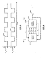
- FIG. 3 is a timing diagram that illustrates the control signal waveforms generated by the control module of FIG. 2 including alternating charging and discharging of the first and second inductors;
- FIG. 4 is a functional block diagram of a closed-loop control system for a DC/DC converter
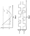
- FIG. 5 is a graph showing the output voltage of the DC/DC converter in FIG. 4 as a function of time
- FIG. 6 is a timing diagram that illustrates the control signal waveforms generated by the control module of FIG. 4 including an overlap of the charging pattern for the first and second inductors;
- FIG. 7 is an electrical schematic of the closed-loop DC/DC control system of FIG. 4;
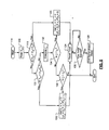
- FIG. 8 is a flowchart illustrating steps performed by the control module of FIGs. 4 and 7 including initiating same-phase operation of the first and second inductors for a predetermined time period;
- FIG. 9 is a flowchart illustrating steps performed by the control module of FIGs. 4 and 7 including initiating same-phase operation of the first and second inductors while a variable is outside of a predetermined range.
- module refers to an application specific integrated circuit (ASIC), an electronic circuit, a processor (shared, dedicated, or group) and memory that execute one or more software or firmware programs, a combinational logic circuit, and/or other suitable components that provide the described functionality.
- ASIC application specific integrated circuit
- processor shared, dedicated, or group
- memory that execute one or more software or firmware programs, a combinational logic circuit, and/or other suitable components that provide the described functionality.
- an open-loop control system 28 for a DC/DC converter 30 includes a control module 32.
- the DC/DC converter 30 includes first, second, third, and fourth transistors 34, 36, 38, and 40, respectively.
- First and second inductors 42 and 44 form a coupled inductor circuit 46.
- a first end of the first inductor 46 communicates with the source of the third transistor 38 and the drain of the fourth transistor 40.
- a first end of the second inductor 44 communicates with the source of the first transistor 34 and the drain of the second transistor 36.
- a first end of a capacitor 48 communicates with the second ends of the first and second inductors 42 and 44, respectively.
- a second end of the capacitor 48 communicates with the sources of the second and fourth transistors 36 and 40, respectively.
- a first end of a current source 50 communicates with the first end of the capacitor 48 and the second ends of the first and second inductors 42 and 44, respectively.
- a second end of the current source 50 communicates with the sources of the second and fourth transistors 36 and 40, respectively, and the second end of the capacitor 48.
- a input DC voltage 52 ( V in ) of the DC/DC converter 30 communicates with the drains of the first and third transistors 34 and 38, respectively.
- An output DC voltage 54 ( V out ) of the DC/DC converter 30 in referenced from the second ends of the first and second inductors 42 and 44, respectively, the first end of the capacitor 48, and the first end of the current source 50.
- the control module 32 generates first, second, third, and fourth control signals U 2 , D 2 , U 1 , and D 1 that communicate with gates (or control terminals) of the first, second, third, and fourth transistors 34, 36, 38, and 40, respectively.
- the control module 32 charges the first inductor 42 by setting the third and fourth control signals U 1 and D 1 , respectively, high (or low) and discharges the first inductor 42 by setting the third and fourth control signals U 1 and D 1 , respectively, low (or high).
- the control module 32 charges the second inductor 44 by setting the first and second control signals U 2 and D 2 , respectively, high (or low) and discharges the second inductor 44 by setting the first and second control signals U 2 and D 2 , respectively, low (or high). Based on a frequency and duty cycle of the control signals, the DC/DC converter 30 transforms the input DC voltage 52 into the output DC voltage 54, which is at a different level than the input DC voltage 52.
- signal waveforms of the third and fourth control signals U 1 and D 1 , respectively, indicated by 62, and of the first and second control signals U 2 and D 2 , respectively, indicated by 64, are shown as square waveforms.
- the control module 32 maintains the signal waveforms for the first, second, third, and fourth control signals U 2 , D 2 , U 1 , and D 1 , respectively, at a predetermined frequency and duty cycle so that the DC/DC converter 30 generates a desired voltage.
- Signal waveforms 62 of the third and fourth control signals U 1 and D 1 , respectively, are complementary (or 180 degrees out-of-phase) to the signal waveforms 64 of the first and second control signals U 2 and D 2 , respectively. Therefore, when the first inductor 42 charges, the second inductor 44 discharges. Likewise, when the first inductor 42 discharges, the second inductor 44 charges.
- An advantage of the open-loop control system 28 of FIG. 2 is that the DC/DC converter 30 has a high efficiency and generates a small voltage ripple.
- the DC/DC converter 30 also has a relatively fast response, which allows the capacitor 48 to be smaller in size.
- the control module 32 maintains the signal waveforms of the first, second, third, and fourth control signals U 2 , D 2 , U 1 , and D 1 , respectively, at a fixed frequency and duty cycle. Therefore, no additional control is required for the open-loop control system 28 during normal operations.
- a closed-loop control system 72 for the DC/DC converter 30 is shown.
- An input of the control module 32 receives the output DC voltage 54 of the DC/DC converter 30.
- the control module 32 also optionally receives voltage signals V x 1 and V x 2 from the first and second inductors 42 and 44, respectively.
- the control module 32 may perform a current estimation based on voltage signals V x 1 and V x 2 to sense a balance of the first and second inductors 42 and 44, respectively.
- the control module 32 ensures that the phases of the signal waveforms for the third and fourth control signals U 1 and D 1 , respectively, are complementary to the phases of the signal waveforms for the first and second control signals U 2 and D 2 , respectively, during normal operations.
- the control module 32 initiates same-phase operation of the control signals when a large voltage or current transient is detected in the DC/DC converter 30 based on the output DC voltage 54.
- the control module 32 initiates same-phase operation of the control signals when a value of the output DC voltage 54 is outside of a predetermined range. For example, the control module 32 sets the signal waveforms of the control signals low (or high) when the value of the output DC voltage 54 is greater than a first predetermined voltage. This allows both the first and second inductors 42 and 44, respectively, to discharge. The control module 32 sets the signal waveforms of the control signals high (or low) when the value of the output DC voltage 54 is less than a second predetermined voltage. This allows both the first and second inductors 42 and 44, respectively, to charge.
- the control module 32 may revert back to complementary operation of the control signals when the value of the output DC voltage 54 is back within the predetermined range. Alternatively, the control module 32 may revert back to complementary operation of the control signals after a predetermined time period.
- the predetermined time period is a function of one or more circuit conditions such as a current or voltage magnitude within the DC/DC converter 30.
- the control module 32 initiates same-phase operation of the control signals when a value of the current flowing through the capacitor 48 is outside of a predetermined range. For example, the control module 32 sets the signal waveforms of the control signals low (or high) when the current flowing through the capacitor 48 is greater than a first predetermined current. This allows both the first and second inductors 42 and 44, respectively, to discharge.
- the control module 32 sets the signal waveforms of the control signals high (or low) when the current flowing through the capacitor 48 is less than a second predetermined current. This allows both the first and second inductors 42 and 44, respectively, to charge. As in the case of the voltage threshold, the control module 32 may revert back to complementary operation of the control signals when the current flowing through the capacitor 48 is back within the predetermined range. Alternatively, the control module 32 may revert back to complementary operation of the control signals after a predetermined time period.
- the control module 32 estimates the current, I c , flowing through the capacitor 48 based on the output DC voltage 54, V out .
- the output DC voltage 54 decreases from a first predetermined voltage ( V L 1 ), indicated by 82, to a second predetermined voltage ( V L 2 ), indicated by 84.
- the control module 32 determines when the current flowing through the capacitor 48 is outside of the predetermined range. Alternatively, the control module 32 may estimate the current flowing through the capacitor 48 based on an average value of V out during a predetermined time period.
- the T overlap period identifies when the control module 32 maintains same-phase operation of the control signals. Before and after the T overlap period, the control module 32 maintains complementary operation of the control signals.
- the control module 32 includes a voltage compare module 102 and a control signal generator 104.
- the control module 32 also optionally includes a current detection module 106.
- a first input of the voltage compare module 102 receives the output DC voltage 54 from the DC/DC converter 30.
- a second input of the voltage compare module 102 receives a predetermined voltage.
- the voltage compare module 102 compares the output DC voltage 54 and the predetermined voltage to determine when the output DC voltage 54 is greater than or less than the predetermined voltage.
- the voltage compare module 102 outputs the result to the control signal generator 104.
- Inputs of the optional current detection module 106 receive the voltage signals V x 1 and V x 2 from the first and second inductors 42 and 44, respectively.
- the current detection module 106 computes the difference between V x 1 and V x 2 and transmits the difference to the control signal generator 104.
- the control signal generator 104 generates the first, second, third, and fourth control signals U 2 , D 2 , U 1 and D 1 , respectively, based on values of the control signals from the voltage compare module 102 and/or the current detection module 106.
- the control signal generator 104 transmits the first, second, third, and fourth control signals U 2 , D 2 , U 1 and D 1 , respectively, to the gates of the first, second, third, and fourth transistors 34, 36, 38, and 40, respectively, in the DC/DC converter 30.
- a first closed-loop control algorithm begins in step 114.
- control reads the value of the output DC voltage 54 from the DC/DC converter 30.
- control determines whether the output DC voltage 54 is greater than a first predetermined voltage plus a threshold.. If true, control proceeds to step 120. If false, control proceeds to step 122.
- control initiates same-phase operation of the control signals by setting the signal waveforms of the control signals low (or high).
- control resets a timer.
- control determines whether the timer has expired. If false, control loops to step 126. If true, control proceeds to step 128.
- step 128 the control module 32 reverts back to complementary operation of the control signals and control ends.
- step 122 control determines whether the output DC voltage 54 is less than a second predetermined voltage minus a threshold. For example, the thresholds in steps 118 and 122 may be equal and/or the first and second predetermined voltages may be equal. If true, control proceeds to step 130. If false, control proceeds to step 132.
- step 130 the control module 32 initiates same-phase operation of the control signals by setting the signal waveforms of the control signals high (or low) and control proceeds to step 124.
- step 132 the control module 32 estimates the current flowing through the capacitor 48 in the DC/DC converter 30.
- step 134 control determines whether the current flowing through the capacitor 48 is greater than a first predetermined current. If true, control proceeds to step 120. If false, control proceeds to step 136.
- step 136 control determines whether the current flowing through the capacitor 48 is less than a second predetermined current. For example, the second predetermined current may be equal in magnitude to the first predetermined current and have an opposite polarity. If true, control proceeds to step 130. If false, control ends.
- a second closed-loop control algorithm begins in step 144.
- control reads the value of the output DC voltage 54 from the DC/DC converter 30.
- control determines whether the output DC voltage 54 is greater than a first predetermined voltage plus a threshold. If true, control proceeds to step 150. If false, control proceeds to step 152.
- the control module 32 initiates same-phase operation of the control signals by setting the signal waveforms of the control signals low (or high).
- step 154 control determines whether the output DC voltage 54 is less than the first predetermined voltage plus the threshold. Is false, control loops to step 154. If true, control proceeds to step 156. In step 156, the control module 32 reverts back to complementary operation of the control signals and control ends.
- control determines whether the output DC voltage 54 is less than a second predetermined voltage minus a threshold.
- the thresholds in steps 148 and 152 may be equal and/or the first and second predetermined voltages may be equal. If true, control proceeds to step 158. If false, control proceeds to step 160.
- step 158 the control module 32 initiates same-phase operation of the control signals by setting the signal waveforms of the control signals high (or low).
- step 162 control determines whether the output DC voltage 54 is greater than the second predetermined voltage minus the threshold. If false, control loops to step 162. If true, control proceeds to step 156.
- the control module 32 estimates the current flowing through the capacitor 48 in the DC/DC converter 30.
- step 164 control determines whether the current flowing through the capacitor 48 is greater than a first predetermined current. If true, control proceeds to step 166. If false, control proceeds to step 168. In step 166, the control module 32 initiates same-phase operation of the control signals by setting the signal waveforms of the control signals low (or high). In step 170, control determines whether the current flowing through the capacitor 48 is less than the first predetermined current. If false, control loops to step 170. If true, control proceeds to step 156.
- control determines whether the current flowing through the capacitor 48 is less than a second predetermined current.
- the second predetermined current may be equal in magnitude to the first predetermined current and have an opposite polarity. If false, control ends. If true, control proceeds to step 172.
- the control module 32 initiates same-phase operation of the control signals by setting the signal waveforms of the control signals high (or low).
- control determines whether the current flowing through the capacitor 48 is greater than the second predetermined current. If false, control loops to step 174. If true, control proceeds to step 156.
- the present invention allows for closed-loop digital control of a coupled-inductor DC/DC converter 30.
- the methods of the present invention may also be employed to control other electronic circuits of a similar nature.
- the control module 32 is capable of detecting large voltage or current transients in the circuitry of the DC/DC converter 30. Therefore, the previous constraint of constant complementary operation of the control signals is relaxed. This allows the DC/DC converter 30 to achieve an even faster response and requires an even smaller output capacitor 48 than DC/DC converters that employ open-loop control systems.
Landscapes
- Engineering & Computer Science (AREA)
- Power Engineering (AREA)
- Dc-Dc Converters (AREA)
Applications Claiming Priority (1)
| Application Number | Priority Date | Filing Date | Title |
|---|---|---|---|
| US10/890,491 US7190152B2 (en) | 2004-07-13 | 2004-07-13 | Closed-loop digital control system for a DC/DC converter |
Publications (3)
| Publication Number | Publication Date |
|---|---|
| EP1617548A2 true EP1617548A2 (de) | 2006-01-18 |
| EP1617548A3 EP1617548A3 (de) | 2008-03-26 |
| EP1617548B1 EP1617548B1 (de) | 2011-02-09 |
Family
ID=35149611
Family Applications (1)
| Application Number | Title | Priority Date | Filing Date |
|---|---|---|---|
| EP05012809A Expired - Lifetime EP1617548B1 (de) | 2004-07-13 | 2005-06-14 | Digitales Steuersystem mit geschlossener Schleife für Gleichstromwandler |
Country Status (6)
| Country | Link |
|---|---|
| US (3) | US7190152B2 (de) |
| EP (1) | EP1617548B1 (de) |
| JP (1) | JP4652901B2 (de) |
| CN (1) | CN1722592B (de) |
| DE (1) | DE602005026233D1 (de) |
| TW (1) | TWI381606B (de) |
Families Citing this family (21)
| Publication number | Priority date | Publication date | Assignee | Title |
|---|---|---|---|---|
| US7872454B2 (en) * | 2003-08-21 | 2011-01-18 | Marvell World Trade Ltd. | Digital low dropout regulator |
| US8324872B2 (en) * | 2004-03-26 | 2012-12-04 | Marvell World Trade, Ltd. | Voltage regulator with coupled inductors having high coefficient of coupling |
| US7190152B2 (en) * | 2004-07-13 | 2007-03-13 | Marvell World Trade Ltd. | Closed-loop digital control system for a DC/DC converter |
| JP2010124638A (ja) * | 2008-11-21 | 2010-06-03 | Sanken Electric Co Ltd | 電源装置 |
| EP2425432A4 (de) * | 2009-04-30 | 2015-05-13 | Green Plug Inc | Bidirektionale multifunktionskommunikation und biasleistungsarchitektur für stromversorgungssteuerung |
| JP4764499B2 (ja) * | 2009-08-05 | 2011-09-07 | 本田技研工業株式会社 | Dc/dcコンバータ及びそのdc/dcコンバータを備えた電力供給システム |
| US8503193B2 (en) * | 2010-08-26 | 2013-08-06 | Astec International Limited | Open loop DC to DC converters with enable/disable circuits |
| US9110488B2 (en) | 2011-06-07 | 2015-08-18 | International Business Machines Corporation | Wide-bandwidth linear regulator |
| KR101871906B1 (ko) * | 2011-06-30 | 2018-06-28 | 삼성디스플레이 주식회사 | Dc-dc 컨버터 및 이를 포함한 유기전계발광 표시장치 |
| US9287792B2 (en) | 2012-08-13 | 2016-03-15 | Flextronics Ap, Llc | Control method to reduce switching loss on MOSFET |
| US9660540B2 (en) | 2012-11-05 | 2017-05-23 | Flextronics Ap, Llc | Digital error signal comparator |
| US9323267B2 (en) * | 2013-03-14 | 2016-04-26 | Flextronics Ap, Llc | Method and implementation for eliminating random pulse during power up of digital signal controller |
| US9494658B2 (en) * | 2013-03-14 | 2016-11-15 | Flextronics Ap, Llc | Approach for generation of power failure warning signal to maximize useable hold-up time with AC/DC rectifiers |
| US9490651B2 (en) | 2013-03-15 | 2016-11-08 | Flextronics Ap, Llc | Sweep frequency mode for magnetic resonant power transmission |
| EP3736956A1 (de) | 2014-04-16 | 2020-11-11 | Apple Inc. | Ansteuerungsschema für schwach gekoppelte spulen |
| US9621053B1 (en) | 2014-08-05 | 2017-04-11 | Flextronics Ap, Llc | Peak power control technique for primary side controller operation in continuous conduction mode |
| US9893627B1 (en) | 2014-08-08 | 2018-02-13 | Flextronics Ap, Llc | Current controlled resonant tank circuit |
| US10122269B2 (en) * | 2016-09-22 | 2018-11-06 | Apple Inc. | Current mode control of a buck converter using coupled inductance |
| US11165347B2 (en) * | 2019-10-17 | 2021-11-02 | Infineon Technologies Austria Ag | Inductive coupled power supply and slope control |
| CN110718953B (zh) * | 2019-11-11 | 2021-05-14 | 广州极飞科技股份有限公司 | 一种充电电路与充电系统 |
| US11876445B2 (en) * | 2020-10-05 | 2024-01-16 | Infineon Technologies Austria Ag | Trans-inductance multi-phase power converters and control |
Citations (2)
| Publication number | Priority date | Publication date | Assignee | Title |
|---|---|---|---|---|
| US6362608B1 (en) | 2001-02-01 | 2002-03-26 | Maxim Integrated Products, Inc. | Multi-phase switching converters and methods |
| US6628106B1 (en) | 2001-07-30 | 2003-09-30 | University Of Central Florida | Control method and circuit to provide voltage and current regulation for multiphase DC/DC converters |
Family Cites Families (126)
| Publication number | Priority date | Publication date | Assignee | Title |
|---|---|---|---|---|
| US643066A (en) * | 1899-05-22 | 1900-02-06 | Langdon Davies Electric Motor Company | Alternating-current motor. |
| US3579214A (en) | 1968-06-17 | 1971-05-18 | Ibm | Multichannel magnetic head with common leg |
| US3529233A (en) | 1968-10-08 | 1970-09-15 | Adams Russel Co Inc | Lattice type phase shifting network |
| US3851375A (en) | 1972-05-08 | 1974-12-03 | Philips Corp | Method of bonding together mouldings of sintered oxidic ferromagnetic material |
| US4020439A (en) | 1974-02-09 | 1977-04-26 | U.S. Philips Corporation | Inductive stabilizing ballast for a gas and/or vapor discharge lamp |
| JPS5217808A (en) | 1975-07-31 | 1977-02-10 | Olympus Optical Co Ltd | Manufacturing method of magnetic head |
| DE2714426C3 (de) | 1977-03-31 | 1981-02-26 | Siemens Ag, 1000 Berlin Und 8000 Muenchen | Als Tiefpaß- oder als Laufzeitglied ausgebildetes passives Schaltungsglied |
| US4214198A (en) | 1977-09-01 | 1980-07-22 | Dynamote Corporation | Electrical power unit |
| EP0003396A1 (de) | 1978-02-01 | 1979-08-08 | Imperial Chemical Industries Plc | Steuerkreis zum Erregen einer elektrisch gezündeten Last |
| US4384321A (en) | 1980-04-29 | 1983-05-17 | California Institute Of Technology | Unity power factor switching regulator |
| NL8100033A (nl) | 1981-01-07 | 1982-08-02 | Philips Nv | Signaaloverdrachtsinrichting met een in stappen instelbare overdrachtskarakteristiek. |
| DE3220737A1 (de) | 1982-06-02 | 1983-12-08 | Siemens AG, 1000 Berlin und 8000 München | Streufeldarme funk-entstoerdrossel |
| JPS58224420A (ja) | 1982-06-23 | 1983-12-26 | Matsushita Electric Ind Co Ltd | 磁気ヘツドおよびその製造方法 |
| US4536733A (en) | 1982-09-30 | 1985-08-20 | Sperry Corporation | High frequency inverter transformer for power supplies |
| US4527032A (en) | 1982-11-08 | 1985-07-02 | Armco Inc. | Radio frequency induction heating device |
| US4475143A (en) | 1983-01-10 | 1984-10-02 | Rogers Corporation | Decoupling capacitor and method of manufacture thereof |
| US4583068A (en) | 1984-08-13 | 1986-04-15 | At&T Bell Laboratories | Low profile magnetic structure in which one winding acts as support for second winding |
| JPS6178111A (ja) | 1984-09-25 | 1986-04-21 | Matsushita Electric Works Ltd | 磁心の製法 |
| US4616142A (en) | 1984-12-31 | 1986-10-07 | Sundstrand Corporation | Method of operating parallel-connected semiconductor switch elements |
| JPH0424649Y2 (de) | 1985-02-18 | 1992-06-11 | ||
| US4801912A (en) | 1985-06-07 | 1989-01-31 | American Precision Industries Inc. | Surface mountable electronic device |
| US4803609A (en) | 1985-10-31 | 1989-02-07 | International Business Machines Corporation | D. C. to D. C. converter |
| US4897773A (en) | 1989-05-03 | 1990-01-30 | The Lincoln Electric Company | Inverter output circuit |
| US5006782A (en) | 1989-06-15 | 1991-04-09 | International Rectifier Corporation | Cascaded buck converter circuit with reduced power loss |
| US5010261A (en) | 1989-12-08 | 1991-04-23 | General Electric Company | Lossless gate driver circuit for a high frequency converter |
| US5276603A (en) * | 1990-05-03 | 1994-01-04 | Crown International, Inc. | Sixteen level power supply with asynchronous controller |
| US5132888A (en) * | 1991-01-07 | 1992-07-21 | Unisys Corporation | Interleaved bridge converter |
| US5187428A (en) | 1991-02-26 | 1993-02-16 | Miller Electric Mfg. Co. | Shunt coil controlled transformer |
| NL9100445A (nl) | 1991-03-13 | 1992-10-01 | Philips Nv | Voedingsschakeling. |
| US5079498A (en) | 1991-03-26 | 1992-01-07 | Vickers Systems Limited | Digital pulse-width-modulation generator for current control |
| US5303115A (en) | 1992-01-27 | 1994-04-12 | Raychem Corporation | PTC circuit protection device comprising mechanical stress riser |
| US5186647A (en) | 1992-02-24 | 1993-02-16 | At&T Bell Laboratories | High frequency electrical connector |
| US5204809A (en) * | 1992-04-03 | 1993-04-20 | International Business Machines Corporation | H-driver DC-to-DC converter utilizing mutual inductance |
| JPH066195A (ja) | 1992-06-18 | 1994-01-14 | Mitsubishi Electric Corp | 出力ドライバ回路 |
| US5509691A (en) | 1992-10-26 | 1996-04-23 | Gao Gesellschaft Fur Automation Und Organisation Mbh | Security element in the form of threads or strips to be embedded in security documents and a method for producing and testing the same |
| WO1994011799A1 (en) | 1992-11-10 | 1994-05-26 | Motorola, Inc. | Switching regulator and amplifier system |
| US5444600A (en) | 1992-12-03 | 1995-08-22 | Linear Technology Corporation | Lead frame capacitor and capacitively-coupled isolator circuit using the same |
| US5402329A (en) | 1992-12-09 | 1995-03-28 | Ernest H. Wittenbreder, Jr. | Zero voltage switching pulse width modulated power converters |
| US5500629A (en) | 1993-09-10 | 1996-03-19 | Meyer Dennis R | Noise suppressor |
| US5475296A (en) | 1994-04-15 | 1995-12-12 | Adept Power Systems, Inc. | Digitally controlled switchmode power supply |
| US5481238A (en) | 1994-04-19 | 1996-01-02 | Argus Technologies Ltd. | Compound inductors for use in switching regulators |
| US5610807A (en) * | 1994-10-14 | 1997-03-11 | Matsushita Electric Works, Ltd. | Power converting system with a plurality of charging capacitors |
| US5687067A (en) | 1995-05-30 | 1997-11-11 | Philips Electronics North America Corporation | Low noise controller for pulse width modulated converters |
| JP3599205B2 (ja) | 1995-09-12 | 2004-12-08 | Tdk株式会社 | ノイズ抑制用インダクタ素子 |
| WO1997006660A2 (en) | 1995-08-15 | 1997-02-27 | Bourns, Multifuse (Hong Kong), Ltd. | Surface mount conductive polymer devices and method for manufacturing such devices |
| US5636107A (en) | 1995-11-15 | 1997-06-03 | International Power Devices, Inc. | DC-DC converters |
| FR2743458B1 (fr) | 1995-11-30 | 1998-03-27 | Sgs Thomson Microelectronics | Circuit de transmission de signaux |
| US5875103A (en) * | 1995-12-22 | 1999-02-23 | Electronic Measurements, Inc. | Full range soft-switching DC-DC converter |
| US5654881A (en) | 1996-03-01 | 1997-08-05 | Lockheed Martin Corporation | Extended range DC-DC power converter circuit |
| US5808537A (en) | 1996-09-16 | 1998-09-15 | Kabushiki Kaisha Toyoda Jidoshokki Seisakusho | Inductor core for transferring electric power to a conveyor carriage |
| US5877611A (en) | 1996-10-09 | 1999-03-02 | Lucent Technologies Inc. | Simple and efficient switching regulator for fast transient loads such as microprocessors |
| JP3480201B2 (ja) * | 1996-11-06 | 2003-12-15 | 松下電器産業株式会社 | インターリーブ方式スイッチングコンバータ |
| GB9622344D0 (en) | 1996-10-28 | 1997-01-08 | Norweb Plc | Inductor |
| US6054764A (en) | 1996-12-20 | 2000-04-25 | Texas Instruments Incorporated | Integrated circuit with tightly coupled passive components |
| US5889373A (en) | 1996-12-30 | 1999-03-30 | General Electric Company | Fluorescent lamp ballast with current feedback using a dual-function magnetic device |
| EP0954899A2 (de) | 1997-01-24 | 1999-11-10 | Fische, LLC | Hocheffizienter stromrichter |
| US6144269A (en) | 1997-06-10 | 2000-11-07 | Fuji Electric Co., Ltd. | Noise-cut LC filter for power converter with overlapping aligned coil patterns |
| JPH1111198A (ja) * | 1997-06-23 | 1999-01-19 | Nec Home Electron Ltd | 乗員検知システム |
| US6512437B2 (en) | 1997-07-03 | 2003-01-28 | The Furukawa Electric Co., Ltd. | Isolation transformer |
| JPH1174125A (ja) | 1997-08-29 | 1999-03-16 | Fuji Elelctrochem Co Ltd | ビーズインダクタ |
| FR2768527B1 (fr) | 1997-09-18 | 2000-07-13 | Sgs Thomson Microelectronics | Regulateur de tension |
| US6310534B1 (en) | 1997-10-14 | 2001-10-30 | Vacuumschmelze Gmbh | Radio interference suppression choke |
| JP3618534B2 (ja) | 1997-11-28 | 2005-02-09 | 同和鉱業株式会社 | 光通信用ランプ装置とその製造方法 |
| US6049264A (en) | 1997-12-09 | 2000-04-11 | Siemens Automotive Corporation | Electromagnetic actuator with composite core assembly |
| JP3148171B2 (ja) | 1998-01-12 | 2001-03-19 | 株式会社日本プロテクター | スイッチングレギュレータ |
| JPH11204354A (ja) | 1998-01-17 | 1999-07-30 | Kobe:Kk | ノイズ遮断変圧器 |
| US6184666B1 (en) | 1998-03-09 | 2001-02-06 | 3Dlabs Inc. Ltd. | Buck converter with parallel switches |
| JP4020177B2 (ja) | 1998-05-21 | 2007-12-12 | 三菱電機株式会社 | 変成器 |
| DE19837639A1 (de) | 1998-08-19 | 2000-03-02 | Siemens Ag | Schaltungsanordnung und Verfahren eines Überlastschutzes in einem Wandler |
| US6057665A (en) | 1998-09-18 | 2000-05-02 | Fire Wind & Rain Technologies Llc | Battery charger with maximum power tracking |
| US6084790A (en) | 1999-01-07 | 2000-07-04 | Astec International Limited | Circuit to ensure equal current sharing and switching losses between parallel power devices |
| US6683522B2 (en) | 1999-02-24 | 2004-01-27 | Milli Sensor Systems & Actuators, Inc. | Planar miniature inductors and transformers |
| CN1239052C (zh) * | 1999-05-14 | 2006-01-25 | 皇家菲利浦电子有限公司 | 电路设置 |
| US6272023B1 (en) * | 1999-05-15 | 2001-08-07 | Technical Witts, Inc | High efficiency coupled inductor soft switching power converters |
| US6147886A (en) * | 1999-05-15 | 2000-11-14 | Technical Witts, Inc. | Dual opposed interleaved coupled inductor soft switching converters |
| AR024092A1 (es) | 1999-05-26 | 2002-09-04 | Abb Ab | Dispositivos de induccion con entrehierros distribuidos |
| JP3366916B2 (ja) | 1999-06-03 | 2003-01-14 | スミダコーポレーション株式会社 | インダクタンス素子 |
| US6545450B1 (en) | 1999-07-02 | 2003-04-08 | Advanced Energy Industries, Inc. | Multiple power converter system using combining transformers |
| US6144565A (en) * | 1999-07-20 | 2000-11-07 | Semtech Corporation | Variation on a single-ended primary inductor converter |
| US6246592B1 (en) | 1999-08-10 | 2001-06-12 | Texas Instruments Incorporated | Unique power supply architecture with cascaded converters for large input-to-output step-down ratio |
| US6259235B1 (en) | 1999-08-26 | 2001-07-10 | Tyco Electronics Logistics Ag | Active clamp for power converter and method of operation thereof |
| US6272025B1 (en) | 1999-10-01 | 2001-08-07 | Online Power Supply, Inc. | Individual for distributed non-saturated magnetic element(s) (referenced herein as NSME) power converters |
| US6215290B1 (en) | 1999-11-15 | 2001-04-10 | Semtech Corporation | Multi-phase and multi-module power supplies with balanced current between phases and modules |
| JP3402361B2 (ja) | 1999-12-28 | 2003-05-06 | 横河電機株式会社 | スイッチング電源 |
| US6255805B1 (en) * | 2000-02-04 | 2001-07-03 | Motorola, Inc. | Device for electrical source sharing |
| US6229289B1 (en) | 2000-02-25 | 2001-05-08 | Cadence Design Systems, Inc. | Power converter mode transitioning method and apparatus |
| US6459349B1 (en) | 2000-03-06 | 2002-10-01 | General Electric Company | Circuit breaker comprising a current transformer with a partial air gap |
| JP3505122B2 (ja) * | 2000-03-14 | 2004-03-08 | 株式会社日立製作所 | 電源装置 |
| US6166527A (en) | 2000-03-27 | 2000-12-26 | Linear Technology Corporation | Control circuit and method for maintaining high efficiency in a buck-boost switching regulator |
| US6538905B2 (en) * | 2000-04-04 | 2003-03-25 | Artesyn Technologies, Inc. | DC-to-DC power converter including at least two cascaded power conversion stages |
| JP4432215B2 (ja) | 2000-06-05 | 2010-03-17 | 株式会社デンソー | 半導体スイッチング素子のゲート駆動回路 |
| US6392902B1 (en) * | 2000-08-31 | 2002-05-21 | Delta Electronics, Inc. | Soft-switched full-bridge converter |
| US6462962B1 (en) * | 2000-09-08 | 2002-10-08 | Slobodan Cuk | Lossless switching DC-to-DC converter |
| DE60137058D1 (de) | 2000-09-20 | 2009-01-29 | Det Int Holding Ltd | Planares induktives element |
| AU2001294646A1 (en) | 2000-09-22 | 2002-04-02 | M-Flex Multi-Fineline Electronix, Inc. | Electronic transformer/inductor devices and methods for making same |
| IL138834A0 (en) | 2000-10-03 | 2001-10-31 | Payton Planar Magnetics Ltd | A magnetically biased inductor or flyback transformer |
| JP2002199708A (ja) | 2000-12-22 | 2002-07-12 | Hitachi Ltd | Dc−dcコンバータ |
| US6674274B2 (en) * | 2001-02-08 | 2004-01-06 | Linear Technology Corporation | Multiple phase switching regulators with stage shedding |
| US6784644B2 (en) | 2001-02-22 | 2004-08-31 | Virginia Tech Intellectual Properties, Inc. | Multiphase clamp coupled-buck converter and magnetic integration |
| JP3872331B2 (ja) | 2001-03-07 | 2007-01-24 | 富士通株式会社 | Dc−dcコンバータ及び電源回路 |
| US6362986B1 (en) * | 2001-03-22 | 2002-03-26 | Volterra, Inc. | Voltage converter with coupled inductive windings, and associated methods |
| WO2002095775A1 (en) | 2001-05-21 | 2002-11-28 | Milli Sensor Systems & Actuators, Inc. | Planar miniature inductors and transformers and miniature transformers for millimachined instruments |
| US6512352B2 (en) | 2001-06-07 | 2003-01-28 | Koninklijke Philips Electronics N.V. | Active clamp step-down converter with power switch voltage clamping function |
| US6995685B2 (en) | 2001-09-25 | 2006-02-07 | Landis+Gyr, Inc. | Utility meter power arrangements and methods |
| US6747442B2 (en) * | 2002-02-19 | 2004-06-08 | Koninklijke Philips Electronics N.V. | Multiphase integrated DC-to-DC voltage converter |
| JP3624186B2 (ja) * | 2002-03-15 | 2005-03-02 | Tdk株式会社 | スイッチング電源装置用の制御回路及びこれを用いたスイッチング電源装置 |
| US6703815B2 (en) | 2002-05-20 | 2004-03-09 | Texas Instruments Incorporated | Low drop-out regulator having current feedback amplifier and composite feedback loop |
| US7052480B2 (en) | 2002-04-10 | 2006-05-30 | Baxter International Inc. | Access disconnection systems and methods |
| US6686823B2 (en) | 2002-04-29 | 2004-02-03 | Pri Automation, Inc. | Inductive power transmission and distribution apparatus using a coaxial transformer |
| US6822427B2 (en) | 2002-05-01 | 2004-11-23 | Technical Witts, Inc. | Circuits and circuit elements for high efficiency power conversion |
| JP2003332141A (ja) | 2002-05-15 | 2003-11-21 | Tdk Corp | チップ型コモンモードチョークコイル |
| US20030227366A1 (en) | 2002-06-05 | 2003-12-11 | Chang-Liang Lin | Inductor structure and manufacturing method for the inductor structure |
| US6738274B2 (en) | 2002-09-09 | 2004-05-18 | Hewlett-Packard Development Company, L.P. | Power supply with integrated bridge and boost circuit |
| US6798177B1 (en) | 2002-10-15 | 2004-09-28 | Arques Technology, Inc. | Boost-buck cascade converter for pulsating loads |
| US7161342B2 (en) | 2002-10-25 | 2007-01-09 | Marvell World Trade Ltd. | Low loss DC/DC converter |
| KR100498233B1 (ko) | 2002-10-31 | 2005-07-01 | 한국전자통신연구원 | 선입선출 메모리 회로 및 그 구현 방법 |
| US6853568B2 (en) | 2003-05-20 | 2005-02-08 | Delta Electronics, Inc. | Isolated voltage regulator with one core structure |
| JP4110470B2 (ja) * | 2003-05-28 | 2008-07-02 | 株式会社デンソー | 多相多重制御方式 |
| JP4270945B2 (ja) * | 2003-05-30 | 2009-06-03 | 富士通テレコムネットワークス株式会社 | 電源 |
| US7023313B2 (en) | 2003-07-16 | 2006-04-04 | Marvell World Trade Ltd. | Power inductor with reduced DC current saturation |
| US7489219B2 (en) * | 2003-07-16 | 2009-02-10 | Marvell World Trade Ltd. | Power inductor with reduced DC current saturation |
| US7872454B2 (en) * | 2003-08-21 | 2011-01-18 | Marvell World Trade Ltd. | Digital low dropout regulator |
| US7760525B2 (en) * | 2003-08-21 | 2010-07-20 | Marvell World Trade Ltd. | Voltage regulator |
| US8324872B2 (en) * | 2004-03-26 | 2012-12-04 | Marvell World Trade, Ltd. | Voltage regulator with coupled inductors having high coefficient of coupling |
| JP2006025553A (ja) * | 2004-07-08 | 2006-01-26 | Canon Inc | 電源装置 |
| US7190152B2 (en) * | 2004-07-13 | 2007-03-13 | Marvell World Trade Ltd. | Closed-loop digital control system for a DC/DC converter |
-
2004
- 2004-07-13 US US10/890,491 patent/US7190152B2/en not_active Expired - Fee Related
-
2005
- 2005-06-14 EP EP05012809A patent/EP1617548B1/de not_active Expired - Lifetime
- 2005-06-14 DE DE602005026233T patent/DE602005026233D1/de not_active Expired - Lifetime
- 2005-06-17 TW TW094120283A patent/TWI381606B/zh not_active IP Right Cessation
- 2005-06-17 CN CN200510077553.8A patent/CN1722592B/zh not_active Expired - Lifetime
- 2005-06-20 JP JP2005179978A patent/JP4652901B2/ja not_active Expired - Fee Related
-
2007
- 2007-02-23 US US11/710,384 patent/US7679347B2/en not_active Expired - Lifetime
-
2010
- 2010-03-15 US US12/723,867 patent/US8183846B2/en not_active Expired - Lifetime
Patent Citations (2)
| Publication number | Priority date | Publication date | Assignee | Title |
|---|---|---|---|---|
| US6362608B1 (en) | 2001-02-01 | 2002-03-26 | Maxim Integrated Products, Inc. | Multi-phase switching converters and methods |
| US6628106B1 (en) | 2001-07-30 | 2003-09-30 | University Of Central Florida | Control method and circuit to provide voltage and current regulation for multiphase DC/DC converters |
Also Published As
| Publication number | Publication date |
|---|---|
| EP1617548A3 (de) | 2008-03-26 |
| CN1722592B (zh) | 2015-06-24 |
| US20070176585A1 (en) | 2007-08-02 |
| JP4652901B2 (ja) | 2011-03-16 |
| US7679347B2 (en) | 2010-03-16 |
| JP2006034091A (ja) | 2006-02-02 |
| TWI381606B (zh) | 2013-01-01 |
| US7190152B2 (en) | 2007-03-13 |
| EP1617548B1 (de) | 2011-02-09 |
| US20100171478A1 (en) | 2010-07-08 |
| DE602005026233D1 (de) | 2011-03-24 |
| TW200614622A (en) | 2006-05-01 |
| CN1722592A (zh) | 2006-01-18 |
| US8183846B2 (en) | 2012-05-22 |
| US20060013023A1 (en) | 2006-01-19 |
Similar Documents
| Publication | Publication Date | Title |
|---|---|---|
| US7679347B2 (en) | Closed-loop digital control system for a DC/DC converter | |
| CN106936314B (zh) | 开关稳压器、控制开关稳压器的方法和电子设备 | |
| JP3511195B2 (ja) | 電圧変換回路 | |
| US7224591B2 (en) | Charge pump DC/DC converter circuit | |
| US7019497B2 (en) | Circuits and methods for synchronizing non-constant frequency switching regulators with a phase locked loop | |
| EP1309077B1 (de) | Verfahren und Vorrichtung zur Messung des Ausgangsstroms des Induktors in einem Gleichstrom-Gleichstromwandler | |
| KR100912865B1 (ko) | 스위칭 레귤레이터 및 그 스위칭 레귤레이터를 구비하는반도체 장치 | |
| US11522455B2 (en) | Power converter for detecting oscillation of output voltage | |
| CN202663300U (zh) | 一种开关调节器及其控制电路 | |
| US7161333B2 (en) | System and method for determining load current in switching regulators operable in pulse skipping mode | |
| WO2009111438A2 (en) | High-side sensing of zero inductor current for step down dc-dc converter | |
| US12218587B2 (en) | Systems and methods for controlling operation modes of DC-to-DC voltage converters | |
| US20180294724A1 (en) | Power regulator with prevention of inductor current reversal | |
| US11444538B2 (en) | Switching regulator based on load estimation and operating method thereof | |
| US12341421B2 (en) | Power converter control module | |
| CN113410989B (zh) | 数字升压电路及其控制方法、电子设备 | |
| JP2018129908A (ja) | Dc/dcコンバータおよびその制御回路、制御方法および車載電装機器 | |
| US20080258699A1 (en) | Converter Circuit with Improved Efficiency | |
| CN119519429A (zh) | 在低负载下的功率转换器效率提升,以保持最大恒定开关频率操作范围 | |
| HK1157079B (en) | Power supply controller and method | |
| HK1157079A1 (zh) | 電源控制器和方法 |
Legal Events
| Date | Code | Title | Description |
|---|---|---|---|
| PUAI | Public reference made under article 153(3) epc to a published international application that has entered the european phase |
Free format text: ORIGINAL CODE: 0009012 |
|
| AK | Designated contracting states |
Kind code of ref document: A2 Designated state(s): AT BE BG CH CY CZ DE DK EE ES FI FR GB GR HU IE IS IT LI LT LU MC NL PL PT RO SE SI SK TR |
|
| AX | Request for extension of the european patent |
Extension state: AL BA HR LV MK YU |
|
| PUAL | Search report despatched |
Free format text: ORIGINAL CODE: 0009013 |
|
| AK | Designated contracting states |
Kind code of ref document: A3 Designated state(s): AT BE BG CH CY CZ DE DK EE ES FI FR GB GR HU IE IS IT LI LT LU MC NL PL PT RO SE SI SK TR |
|
| AX | Request for extension of the european patent |
Extension state: AL BA HR LV MK YU |
|
| 17P | Request for examination filed |
Effective date: 20080926 |
|
| AKX | Designation fees paid |
Designated state(s): DE FR GB |
|
| 17Q | First examination report despatched |
Effective date: 20081216 |
|
| GRAP | Despatch of communication of intention to grant a patent |
Free format text: ORIGINAL CODE: EPIDOSNIGR1 |
|
| GRAS | Grant fee paid |
Free format text: ORIGINAL CODE: EPIDOSNIGR3 |
|
| GRAA | (expected) grant |
Free format text: ORIGINAL CODE: 0009210 |
|
| AK | Designated contracting states |
Kind code of ref document: B1 Designated state(s): DE FR GB |
|
| REG | Reference to a national code |
Ref country code: GB Ref legal event code: FG4D |
|
| REF | Corresponds to: |
Ref document number: 602005026233 Country of ref document: DE Date of ref document: 20110324 Kind code of ref document: P |
|
| REG | Reference to a national code |
Ref country code: DE Ref legal event code: R096 Ref document number: 602005026233 Country of ref document: DE Effective date: 20110324 |
|
| PLBE | No opposition filed within time limit |
Free format text: ORIGINAL CODE: 0009261 |
|
| STAA | Information on the status of an ep patent application or granted ep patent |
Free format text: STATUS: NO OPPOSITION FILED WITHIN TIME LIMIT |
|
| 26N | No opposition filed |
Effective date: 20111110 |
|
| REG | Reference to a national code |
Ref country code: DE Ref legal event code: R097 Ref document number: 602005026233 Country of ref document: DE Effective date: 20111110 |
|
| REG | Reference to a national code |
Ref country code: FR Ref legal event code: PLFP Year of fee payment: 12 |
|
| REG | Reference to a national code |
Ref country code: FR Ref legal event code: PLFP Year of fee payment: 13 |
|
| REG | Reference to a national code |
Ref country code: FR Ref legal event code: PLFP Year of fee payment: 14 |
|
| PGFP | Annual fee paid to national office [announced via postgrant information from national office to epo] |
Ref country code: FR Payment date: 20180626 Year of fee payment: 14 |
|
| PGFP | Annual fee paid to national office [announced via postgrant information from national office to epo] |
Ref country code: GB Payment date: 20190627 Year of fee payment: 15 |
|
| PG25 | Lapsed in a contracting state [announced via postgrant information from national office to epo] |
Ref country code: FR Free format text: LAPSE BECAUSE OF NON-PAYMENT OF DUE FEES Effective date: 20190630 |
|
| GBPC | Gb: european patent ceased through non-payment of renewal fee |
Effective date: 20200614 |
|
| PG25 | Lapsed in a contracting state [announced via postgrant information from national office to epo] |
Ref country code: GB Free format text: LAPSE BECAUSE OF NON-PAYMENT OF DUE FEES Effective date: 20200614 |
|
| REG | Reference to a national code |
Ref country code: DE Ref legal event code: R082 Ref document number: 602005026233 Country of ref document: DE Representative=s name: GRUENECKER PATENT- UND RECHTSANWAELTE PARTG MB, DE Ref country code: DE Ref legal event code: R081 Ref document number: 602005026233 Country of ref document: DE Owner name: MARVELL ASIA PTE, LTD., SG Free format text: FORMER OWNER: MARVELL WORLD TRADE LTD., ST. MICHAEL, BB |
|
| P01 | Opt-out of the competence of the unified patent court (upc) registered |
Effective date: 20230508 |
|
| PGFP | Annual fee paid to national office [announced via postgrant information from national office to epo] |
Ref country code: DE Payment date: 20240627 Year of fee payment: 20 |
|
| REG | Reference to a national code |
Ref country code: DE Ref legal event code: R071 Ref document number: 602005026233 Country of ref document: DE |