EP1614902B1 - Verdichtungssystem und Verfahren - Google Patents
Verdichtungssystem und Verfahren Download PDFInfo
- Publication number
- EP1614902B1 EP1614902B1 EP05254314A EP05254314A EP1614902B1 EP 1614902 B1 EP1614902 B1 EP 1614902B1 EP 05254314 A EP05254314 A EP 05254314A EP 05254314 A EP05254314 A EP 05254314A EP 1614902 B1 EP1614902 B1 EP 1614902B1
- Authority
- EP
- European Patent Office
- Prior art keywords
- pressure
- refrigerant
- rotary compression
- vane
- compressor
- Prior art date
- Legal status (The legal status is an assumption and is not a legal conclusion. Google has not performed a legal analysis and makes no representation as to the accuracy of the status listed.)
- Expired - Lifetime
Links
Images


Classifications
-
- F—MECHANICAL ENGINEERING; LIGHTING; HEATING; WEAPONS; BLASTING
- F04—POSITIVE - DISPLACEMENT MACHINES FOR LIQUIDS; PUMPS FOR LIQUIDS OR ELASTIC FLUIDS
- F04C—ROTARY-PISTON, OR OSCILLATING-PISTON, POSITIVE-DISPLACEMENT MACHINES FOR LIQUIDS; ROTARY-PISTON, OR OSCILLATING-PISTON, POSITIVE-DISPLACEMENT PUMPS
- F04C28/00—Control of, monitoring of, or safety arrangements for, pumps or pumping installations specially adapted for elastic fluids
- F04C28/06—Control of, monitoring of, or safety arrangements for, pumps or pumping installations specially adapted for elastic fluids specially adapted for stopping, starting, idling or no-load operation
-
- F—MECHANICAL ENGINEERING; LIGHTING; HEATING; WEAPONS; BLASTING
- F04—POSITIVE - DISPLACEMENT MACHINES FOR LIQUIDS; PUMPS FOR LIQUIDS OR ELASTIC FLUIDS
- F04C—ROTARY-PISTON, OR OSCILLATING-PISTON, POSITIVE-DISPLACEMENT MACHINES FOR LIQUIDS; ROTARY-PISTON, OR OSCILLATING-PISTON, POSITIVE-DISPLACEMENT PUMPS
- F04C23/00—Combinations of two or more pumps, each being of rotary-piston or oscillating-piston type, specially adapted for elastic fluids; Pumping installations specially adapted for elastic fluids; Multi-stage pumps specially adapted for elastic fluids
-
- F—MECHANICAL ENGINEERING; LIGHTING; HEATING; WEAPONS; BLASTING
- F01—MACHINES OR ENGINES IN GENERAL; ENGINE PLANTS IN GENERAL; STEAM ENGINES
- F01C—ROTARY-PISTON OR OSCILLATING-PISTON MACHINES OR ENGINES
- F01C21/00—Component parts, details or accessories not provided for in groups F01C1/00 - F01C20/00
- F01C21/08—Rotary pistons
- F01C21/0809—Construction of vanes or vane holders
- F01C21/0818—Vane tracking; control therefor
- F01C21/0827—Vane tracking; control therefor by mechanical means
- F01C21/0845—Vane tracking; control therefor by mechanical means comprising elastic means, e.g. springs
-
- F—MECHANICAL ENGINEERING; LIGHTING; HEATING; WEAPONS; BLASTING
- F01—MACHINES OR ENGINES IN GENERAL; ENGINE PLANTS IN GENERAL; STEAM ENGINES
- F01C—ROTARY-PISTON OR OSCILLATING-PISTON MACHINES OR ENGINES
- F01C21/00—Component parts, details or accessories not provided for in groups F01C1/00 - F01C20/00
- F01C21/08—Rotary pistons
- F01C21/0809—Construction of vanes or vane holders
- F01C21/0818—Vane tracking; control therefor
- F01C21/0854—Vane tracking; control therefor by fluid means
- F01C21/0863—Vane tracking; control therefor by fluid means the fluid being the working fluid
-
- F—MECHANICAL ENGINEERING; LIGHTING; HEATING; WEAPONS; BLASTING
- F04—POSITIVE - DISPLACEMENT MACHINES FOR LIQUIDS; PUMPS FOR LIQUIDS OR ELASTIC FLUIDS
- F04C—ROTARY-PISTON, OR OSCILLATING-PISTON, POSITIVE-DISPLACEMENT MACHINES FOR LIQUIDS; ROTARY-PISTON, OR OSCILLATING-PISTON, POSITIVE-DISPLACEMENT PUMPS
- F04C18/00—Rotary-piston pumps specially adapted for elastic fluids
- F04C18/30—Rotary-piston pumps specially adapted for elastic fluids having the characteristics covered by two or more of groups F04C18/02, F04C18/08, F04C18/22, F04C18/24, F04C18/48, or having the characteristics covered by one of these groups together with some other type of movement between co-operating members
- F04C18/34—Rotary-piston pumps specially adapted for elastic fluids having the characteristics covered by two or more of groups F04C18/02, F04C18/08, F04C18/22, F04C18/24, F04C18/48, or having the characteristics covered by one of these groups together with some other type of movement between co-operating members having the movement defined in group F04C18/08 or F04C18/22 and relative reciprocation between the co-operating members
- F04C18/356—Rotary-piston pumps specially adapted for elastic fluids having the characteristics covered by two or more of groups F04C18/02, F04C18/08, F04C18/22, F04C18/24, F04C18/48, or having the characteristics covered by one of these groups together with some other type of movement between co-operating members having the movement defined in group F04C18/08 or F04C18/22 and relative reciprocation between the co-operating members with vanes reciprocating with respect to the outer member
- F04C18/3562—Rotary-piston pumps specially adapted for elastic fluids having the characteristics covered by two or more of groups F04C18/02, F04C18/08, F04C18/22, F04C18/24, F04C18/48, or having the characteristics covered by one of these groups together with some other type of movement between co-operating members having the movement defined in group F04C18/08 or F04C18/22 and relative reciprocation between the co-operating members with vanes reciprocating with respect to the outer member the inner and outer member being in contact along one line or continuous surfaces substantially parallel to the axis of rotation
- F04C18/3564—Rotary-piston pumps specially adapted for elastic fluids having the characteristics covered by two or more of groups F04C18/02, F04C18/08, F04C18/22, F04C18/24, F04C18/48, or having the characteristics covered by one of these groups together with some other type of movement between co-operating members having the movement defined in group F04C18/08 or F04C18/22 and relative reciprocation between the co-operating members with vanes reciprocating with respect to the outer member the inner and outer member being in contact along one line or continuous surfaces substantially parallel to the axis of rotation the surfaces of the inner and outer member, forming the working space, being surfaces of revolution
-
- F—MECHANICAL ENGINEERING; LIGHTING; HEATING; WEAPONS; BLASTING
- F04—POSITIVE - DISPLACEMENT MACHINES FOR LIQUIDS; PUMPS FOR LIQUIDS OR ELASTIC FLUIDS
- F04C—ROTARY-PISTON, OR OSCILLATING-PISTON, POSITIVE-DISPLACEMENT MACHINES FOR LIQUIDS; ROTARY-PISTON, OR OSCILLATING-PISTON, POSITIVE-DISPLACEMENT PUMPS
- F04C23/00—Combinations of two or more pumps, each being of rotary-piston or oscillating-piston type, specially adapted for elastic fluids; Pumping installations specially adapted for elastic fluids; Multi-stage pumps specially adapted for elastic fluids
- F04C23/001—Combinations of two or more pumps, each being of rotary-piston or oscillating-piston type, specially adapted for elastic fluids; Pumping installations specially adapted for elastic fluids; Multi-stage pumps specially adapted for elastic fluids of similar working principle
-
- F—MECHANICAL ENGINEERING; LIGHTING; HEATING; WEAPONS; BLASTING
- F04—POSITIVE - DISPLACEMENT MACHINES FOR LIQUIDS; PUMPS FOR LIQUIDS OR ELASTIC FLUIDS
- F04C—ROTARY-PISTON, OR OSCILLATING-PISTON, POSITIVE-DISPLACEMENT MACHINES FOR LIQUIDS; ROTARY-PISTON, OR OSCILLATING-PISTON, POSITIVE-DISPLACEMENT PUMPS
- F04C23/00—Combinations of two or more pumps, each being of rotary-piston or oscillating-piston type, specially adapted for elastic fluids; Pumping installations specially adapted for elastic fluids; Multi-stage pumps specially adapted for elastic fluids
- F04C23/008—Hermetic pumps
-
- F—MECHANICAL ENGINEERING; LIGHTING; HEATING; WEAPONS; BLASTING
- F04—POSITIVE - DISPLACEMENT MACHINES FOR LIQUIDS; PUMPS FOR LIQUIDS OR ELASTIC FLUIDS
- F04C—ROTARY-PISTON, OR OSCILLATING-PISTON, POSITIVE-DISPLACEMENT MACHINES FOR LIQUIDS; ROTARY-PISTON, OR OSCILLATING-PISTON, POSITIVE-DISPLACEMENT PUMPS
- F04C29/00—Component parts, details or accessories of pumps or pumping installations, not provided for in groups F04C18/00 - F04C28/00
- F04C29/06—Silencing
Definitions
- the present invention relates to a compression system, a multicylinder rotary compressor constituting the system, and a refrigeration apparatus using the compressor.
- This type of compression system has heretofore comprised a multicylinder rotary compressor, a control device which controls an operation of the multicylinder rotary compressor and the like.
- this multicylinder rotary compressor includes a two-cylinder rotary compressor comprising first and second rotary compression elements.
- the compressor includes a driving element and first and second rotary compression elements driven by a rotation shaft of the driving element, and these elements are housed in a sealed container.
- the first and second rotary compression elements comprise: first and second cylinders; first and second rollers which are fitted into eccentric portions formed in the rotation shaft and which eccentrically rotate in the respective cylinders, respectively; and first and second vanes which abut on the first and second cylinders to partition the insides of the respective cylinders into low-pressure and high-pressure chamber sides.
- the first and second vanes are constantly urged toward the first and second rollers by the spring members.
- a low-pressure refrigerant gas is sucked from a suction passage on the low-pressure chamber sides of the respective cylinders of the first and second rotary compression elements.
- the gas is compressed by operations of each roller and vane to constitute a high-temperature/pressure refrigerant gas, and discharged from the high-pressure chamber side of each cylinder to a discharge muffling chamber via a discharge port. Thereafter, the gas is discharged into the sealed container, and discharged to the outside (see, e.g., Japanese Patent Application Laid-Open No. 5-99172 ).
- a compression system in which a one-cylinder operation and a two-cylinder operation are switchable in accordance with the capacity. That is, either spring member is eliminated from the spring members which urge the first and second vanes of the multicylinder rotary compressor toward the first and second rollers. For example, the spring member is eliminated which urges the second vane toward the second roller.
- a refrigerant pressure is applied as a back pressure of the second vane on discharge sides of both the rotary compression elements by the control device at the two-cylinder operation. Accordingly, the second vane is urged on a second-roller side to perform a compression work.
- pressure pulsation is caused on the back-pressure side of the vane (side opposite to the roller) by the urging operation of the vane with respect to the roller at the time of the operation of the multicylinder rotary compressor.
- the pressure pulsation causes a problem that the follow-up property of the second vane is deteriorated, the vane collides with the second roller, and the collision sound is generated.
- the second roller is brought into an idling state in the second rotary compression element during the one-cylinder operation.
- the equal suction-side pressures are applied to the pressure in the second cylinder and the back pressure of the second vane. Therefore, the second vane protrudes into the second cylinder by the function of the balance between both spaces. Even in this case, there has been a problem that the second vane collides with the second roller, and the collision sound is generated.
- the present invention has been developed to solve the problems of the conventional technique and seeks to avoid generation of a collision sound of a second vane at the time of switching of an operation mode in a compression system comprising a multicylinder rotary compressor in which an only first vane is urged toward a first roller by a spring member.
- the compressor is usable by switching of a first operation mode in which both rotary compression elements perform a compression work and a second operation mode in which an only first rotary compression element substantially performs a compression work.
- a compression system is known from EP-A-1577557 which is prior art pursuant to Article 54(3) and (4) EPC, and from JP 10-259787 .
- Figure 1 is a vertically sectional side view of an inner high pressure type rotary compressor 10 comprising first and second rotary compression elements according to an embodiment of a multicylinder rotary compressor of a compression system CS of the present invention
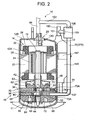
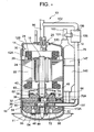
- FIG. 2 is a vertically sectional side view (showing a section different from that of FIG. 1) of the rotary compressor 10 of FIG. 1.
- the compression system CS of the present embodiment constitutes a part of a refrigerant circuit of an air conditioner which is a refrigeration apparatus for conditioning air in a room.
- the rotary compressor 10 of the embodiment is an inner high pressure type rotary compressor.
- elements are stored: an electromotive element 14 which is a driving element disposed in an upper part of an inner space of this sealed container 12; and a rotary compression mechanism section 18 which is disposed under the electromotive element 14 and which is constituted of first and second rotary compression elements 32, 34 driven by a rotation shaft 16 of the electromotive element 14.
- a bottom part of the sealed container 12 is an oil reservoir, and the container comprises a container main body 12A which houses the electromotive element 14 and the rotary compression mechanism section 18; and a substantially bowl-shaped end cap (lid body) 12B which closes an upper opening of the container main body 12A.
- a circular attaching hole 12D is formed in the upper surface of the end cap 12B, and a terminal (wiring is omitted) 20 for supplying a power to the electromotive element 14 is attached to this attaching hole 12D.
- a refrigerant discharge tube 96 described later is attached to the end cap 12B, and one end of the refrigerant introducing tube 96 communicates with the inside of the sealed container 12. Moreover, an attaching base 11 is disposed in a bottom part of the sealed container 12.
- the electromotive element 14 comprises: a stator 22 annularly welded/fixed along an inner peripheral surface of an upper space of the sealed container 12; and a rotor 24 inserted/disposed with a slight interval inside the stator 22. This rotor 24 is fixed to the rotation shaft 16 which passes through a center and extends in a vertical direction.
- the stator 22 has: a laminated member 26 in which donut-shaped electromagnetic steel plates are stacked; and a stator coil 28 which is wound around a tooth portion of the laminated member 26 by a direct winding (concentrated winding) system.
- the rotor 24 is also formed by a laminate member 30 of electromagnetic steel plates in the same manner as in the stator 22.
- first and second rotary compression elements 32, 34 comprise: the intermediate partition plate 36; first and second cylinders 38, 40 disposed on/under the intermediate partition plate 36; first and second rollers 46, 48 which are fitted into upper and lower eccentric portions 42, 44 disposed in the rotation shaft 16 with a phase difference of 180 degrees in the first and second cylinders 38, 40 and which eccentrically rotate in the respective cylinders 38, 40, respectively; first and second vanes 50, 52 which abut on the first and second rollers 46, 48 to partition the insides of the respective cylinders 38, 40 into low-pressure and high-pressure chamber sides; and upper and lower support members 54, 56 which close an upper opening face of the first cylinder 38 and a lower opening face of the second cylinder 40 and which also function as bearings of the rotation shaft 16.
- the first and second cylinders 38, 40 are provided with suction passages 58, 60 which communicate with the insides of the first and second cylinders 38, 40, and the suction passages 58, 60 are connected to refrigerant introducing tubes 92, 94 described later.
- a discharge muffling chamber 62 is disposed on the upper support member 54, and a refrigerant gas compressed by the first rotary compression element 32 is discharged to the discharge muffling chamber 62.
- This discharge muffling chamber 62 is formed in a substantially bowl-shaped cup member 63 having in its center a hole for passing through the rotation shaft 16 and the upper support member 54 which also functions as the bearing of the rotation shaft 16.
- the member covers an electromotive element 14 side (upper side) of the upper support member 54.
- the electromotive element 14 is disposed above the cup member 63 with a predetermined interval from the cup member 63.
- a discharge muffling chamber 64 is disposed in the lower support member 56.
- the chamber is formed by closing of a depressed portion formed in a lower part of the lower support member 56 by a cover which is a wall. That is, the discharge muffling chamber 64 is closed by a lower cover 68 which defines the discharge muffling chamber 64.
- a guide groove 70 is formed in the first cylinder 38, and the above-described first vane 50 is stored in the groove.
- a housing section 70A is formed outside the guide groove 70, that is, in a back surface of the first vane 50, and the section houses a spring 74 which is a spring member. The spring 74 abuts on a back-surface end portion of the first vane 50 to urge the first vane 50 constantly on the side of the first roller 46.
- a discharge-side pressure (high-pressure) described later is also introduced, for example, from the sealed container 12 into the housing section 70A, and is applied as the back pressure of the first vane 50.
- the housing section 70A opens on the sides of the guide groove 70 and sealed container 12 (container main body 12A), a plug 137 formed of a metal is disposed on the sealed container 12 side of the spring 74 housed in the housing section 70A, and the plug prevents the spring 74 from coming off.
- a guide groove 72 is formed in the second cylinder 40 to house the second vane 52, and a back-pressure chamber 72A is formed outside the guide groove 72, that is, on a back-surface side of the second vane 52.
- the back-pressure chamber 72A opens on the sides of the guide groove 72 and the sealed container 12, an opening on the sealed container 12 side communicates with a pipe 75 described later, and the opening is sealed together with the inside of the sealed container 12.
- sleeves 141 and 142 are welded/fixed to positions corresponding to the suction passages 58, 60 of the first and second cylinders 38, 40. These sleeves 141 and 142 are vertically adjacent to each other.
- one end of the refrigerant introducing tube 92 for introducing a refrigerant gas into the first cylinder 38 is inserted/connected into the sleeve 141, and one end of the refrigerant introducing tube 92 communicates with the suction passage 58 of the upper cylinder 38.
- the other end of the refrigerant introducing tube 92 opens in an accumulator 146.
- One end of the refrigerant introducing tube 94 for introducing the refrigerant gas into the second cylinder 40 is inserted/connected into the sleeve 142, and one end of the refrigerant introducing tube 94 communicates with the suction passage 60 of the second cylinder 40.
- the other end of the refrigerant introducing tube 94 opens in the accumulator 146 in the same manner as in the refrigerant introducing tube 92.
- the accumulator 146 is a tank which separates a gas/liquid of a sucked refrigerant, and is attached to the upper side surface of the container main body 12A of the sealed container 12 via a bracket 147. Moreover, the refrigerant introducing tubes 92, 94 are inserted into the accumulator 146 from its bottom portion, and other end openings are positioned in an upper part of the accumulator 146. One end of a refrigerant pipe 100 is inserted into the upper part of the accumulator 146.
- the discharge muffling chamber 64 communicates with the discharge muffling chamber 62 via the upper and lower support members 54, 56, the first and second cylinders 38, 40, or a communication path 120 extending through the intermediate partition plate 36 in an axial center direction (vertical direction).
- the refrigerant gas is compressed by the second rotary compression element 34, and discharged to the discharge muffling chamber 64, and this gas having high-temperature/pressure is then discharged to the discharge muffling chamber 62 via the communication path 120.
- the gas flows with respect to a high-temperature/pressure refrigerant gas compressed by the first rotary compression element 32.
- the discharge muffling chamber 62 communicates with the inside of the sealed container 12 via a hole (not shown) which extends through the cup member 63. Through this hole, the high-pressure refrigerant gas is discharged into the sealed container 12. The gas has been compressed by the first and second rotary compression elements 32 and 34, and discharged to the discharge muffling chamber 62.
- a refrigerant pipe 101 is connected to a middle portion of the refrigerant pipe 100, and the pipe is connected to the pipe 75 via an electromagnetic valve 105.
- a refrigerant pipe 102 also communicates with/is connected to a middle portion of the refrigerant discharge tube 96, and the pipe is connected to the pipe 75 via an electromagnetic valve 106 in the same manner as in the refrigerant pipe 101.
- These electromagnetic valves 105, 106 are controlled in such a manner as to open/close by a controller 210 described later. That is, when the controller 210 opens the valve device 105, and closes the valve device 106, the refrigerant pipe 101 communicates with the pipe 75.
- the controller 210 closes the valve device 105, and opens the valve device 106, the refrigerant discharge tube 96 communicates with the pipe 75. Accordingly, after being discharged from the sealed container 12 and passed through the refrigerant discharge tube 96, a part of the refrigerant on a discharge side of both the rotary compression elements 32, 34 flows into the back-pressure chamber 72A from the pipe 75 via the refrigerant pipe 102. Accordingly, discharge-side pressures of both the rotary compression elements 32, 34 are applied as the back pressure of the second vane 52.
- the controller 210 constitutes a part of the compression system CS of the present invention, and controls a rotation number of the electromotive element 14 of the rotary compressor 10. As described above, the controller also controls the opening/closing of the electromagnetic valve 105 of the refrigerant pipe 101, and the electromagnetic valve 106 of the refrigerant pipe 102.
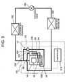
- FIG. 3 shows a refrigerant circuit diagram of the air conditioner constituted using the compression system CS. That is, the compression system CS of the embodiment constitutes a part of the refrigerant circuit of the air conditioner shown in FIG. 3, and comprises the rotary compressor 10, the controller 210 and the like.
- the refrigerant discharge tube 96 of the rotary compressor 10 is connected to an inlet of an outdoor heat exchanger 152.
- the controller 210, rotary compressor 10, and outdoor heat exchanger 152 are disposed in an outdoor unit (not shown) of the air conditioner.
- a pipe connected to an outlet of the outdoor heat exchanger 152 is connected to an expansion valve 154 which is pressure reducing means, and a pipe extending out of the expansion valve 154 is connected to an indoor heat exchanger 156.
- These expansion valve 154 and indoor heat exchanger 156 are disposed in an indoor unit (not shown) of the air conditioner.
- the refrigerant pipe 100 of the rotary compressor 10 is connected to an outlet of the indoor heat exchanger 156.
- oils which are lubricants existing oils are used such as a mineral oil, an alkyl benzene oil, an ether oil, and an ester oil.
- the controller 210 controls a rotation number of the electromotive element 14 of the rotary compressor 10 based on an operation instruction input of an indoor-unit-side controller (not shown) disposed in the indoor unit. In a usual or high load indoor state, the controller 210 executes the first operation mode. In this first operation mode, the controller 210 closes the electromagnetic valve 105 of the refrigerant pipe 101 and the electromagnetic valve 106 of the refrigerant pipe 102.
- the low-pressure refrigerant flows into the accumulator 146 from the refrigerant pipe 100 of the rotary compressor 10. Since the electromagnetic valve 105 of the refrigerant pipe 100 is closed as described above, all the refrigerant passed through the refrigerant pipe 100 flows into the accumulator 146 without flowing into the pipe 75.
- the low-pressure refrigerant which has flown into the accumulator 146 is separated into gas/liquid, and thereafter the only refrigerant gas enters the respective refrigerant discharge tubes 92, 94 which open in the accumulator 146.
- the low-pressure refrigerant gas which has entered the refrigerant introducing tube 92 is passed through the suction passage 58, and sucked on the low-pressure chamber side of the first cylinder 38 of the first rotary compression element 32.
- the refrigerant gas sucked on the low-pressure chamber side of the first cylinder 38 is compressed by the operations of the first roller 46 and the first vane 50 to constitute a high-temperature/pressure refrigerant gas.
- the gas is passed through a discharge port (not shown) from the high-pressure chamber side of the first cylinder 38, and is discharged to the discharge muffling chamber 62.
- the low-pressure refrigerant gas which has flown into the refrigerant introducing tube 94 is passed through the suction passage 60, and sucked on the low-pressure chamber side of the second cylinder 40 of the second rotary compression element 34.
- the refrigerant gas sucked on the low-pressure chamber side of the second cylinder 40 is compressed by the operations of the second roller 48 and the second vane 52.
- a pressure in the back-pressure chamber 72A of the second vane 52 is an intermediate pressure between the suction-side and discharge-side pressures of both the rotary compression elements 32, 34, and the intermediate pressure is applied as the back pressure of the second vane 52.
- the second vane 52 can be sufficiently urged toward the second roller 48 without using any spring member.
- the pressure pulsation is remarkably reduced as compared with a case where the discharge-side pressure is applied as described above.
- the electromagnetic valves 105, 106 are closed to interrupt the flowing of the suction-side and discharge-side refrigerants of both the rotary compression elements 32, 34 from the pipe 75. Therefore, pulsation of the back pressure of the second vane 52 can be further suppressed. Accordingly, the follow-up property of the second vane 52 is improved in the first operation mode, and the compression efficiency of the second rotary compression element 34 is enhanced.
- the refrigerant gas is compressed by the operations of the second roller 48 and second vane 52 to obtain a high-temperature/pressure.
- the gas is passed through a discharge port (not shown) from the high-pressure chamber side of the second cylinder 40, and is discharged to the discharge muffling chamber 64.
- the refrigerant gas discharged to the discharge muffling chamber 64 is discharged to the discharge muffling chamber 62 via the communication path 120, and flows together with the refrigerant gas compressed by the first rotary compression element 32.
- the joined refrigerant gas is discharged into the sealed container 12 from a hole (not shown) extending through the cup member 63.
- the refrigerant in the sealed container 12 is discharged to the outside from the refrigerant discharge tube 96 formed in the end cap 12B of the sealed container 12, and flows into the outdoor heat exchanger 152.
- the refrigerant gas emits heat, pressure of the gas is reduced by the expansion valve 154, and thereafter the gas flows into the indoor heat exchanger 156.
- the refrigerant evaporates, heat is absorbed from air circulated in the room to thereby exert a cooling function, and the inside of the room is cooled.
- the refrigerant emanates from the indoor heat exchanger 156 and is sucked by the rotary compressor 10. The refrigerant repeats this cycle.
- the controller 210 shifts to the second operation mode.
- the only first rotary compression element 32 substantially performs a compression work.
- the operation mode is performed in a case where the inside of the room has a light load and the electromotive element 14 rotates at a low speed in the first operation mode.
- the only first rotary compression element 32 substantially performs the compression work in a small capacity region of the compression system CS, an amount of the refrigerant gas to be compressed can be reduced as compared with a case where the first and second cylinders 38, 40 perform the compression work. Therefore, the rotation number of the electromotive element 14 is raised also at the light load time by the corresponding amount, the operation efficiency of the electromotive element 14 is improved, and a leak loss of the refrigerant can be reduced.
- the controller 210 opens the electromagnetic valve 105 of the refrigerant pipe 101, and closes the electromagnetic valve 106 of the refrigerant pipe 102. Accordingly, the refrigerant pipe 101 communicates with the pipe 75, a suction-side refrigerant of the first rotary compression element 32 flows into the back-pressure chamber 72A, and the suction-side pressure of the first rotary compression element 32 is applied as the back pressure of the second vane 52.
- the controller 210 energizes the stator coil 28 of the electromotive element 14 via the terminal 20 and the wiring (not shown), and rotates the rotor 24 of the electromotive element 14 as described above.
- the first and second rollers 46, 48 are fitted into the upper and lower eccentric portions 42, 44 disposed integrally with the rotation shaft 16, and eccentrically rotate in the first and second cylinders 38, 40.
- the low-pressure refrigerant flows into the accumulator 146 from the refrigerant pipe 100 of the rotary compressor 10. Since the electromagnetic valve 105 of the refrigerant pipe 101 opens at this time as described above, a part of the refrigerant on the suction side of the first rotary compression element 32 passes through the refrigerant pipe 100, and flows into the back-pressure chamber 72A from the refrigerant pipe 101 via the pipe 75. Accordingly, the back-pressure chamber 72A has a suction-side pressure of the first rotary compression element 32, and the suction-side pressure of the first rotary compression element 32 is applied as the back pressure of the second vane 52.
- the suction-side pressures of both the rotary compression elements 32, 34 are applied as the back pressure of the second rotary compression element 34, and this pressure is a low pressure. Therefore, the second vane 52 cannot be urged toward the second roller 48. Therefore, the compression work is not substantially performed in the second rotary compression element 34, and the compression work of the refrigerant is performed only by the first rotary compression element 32 provided with the spring 74.
- the low-pressure refrigerant which has flown into the accumulator 146 is separated into gas/liquid, and thereafter the refrigerant gas only enters the refrigerant discharge tube 92 which opens in the accumulator 146.
- the low-pressure refrigerant gas which has entered the refrigerant introducing tube 92 flows through the suction passage 58, and is sucked on the low-pressure chamber side of the first cylinder 38 of the first rotary compression element 32.
- the refrigerant gas sucked on the low-pressure chamber side of the first cylinder 38 is compressed by the operations of the first roller 46 and the first vane 50 to constitute a high-temperature/pressure refrigerant gas, and the gas is discharged to the discharge muffling chamber 62 from the high-pressure chamber side of the first cylinder 38 through a discharge port (not shown).
- the discharge muffling chamber 62 functions as an expanded type muffling chamber
- the discharge muffling chamber 64 functions as a resonant type muffling chamber in the second operation mode, it is further possible to reduce pressure pulsation of the refrigerant compressed by the first rotary compression element 32. Consequently, a muffling effect can be substantially further enhanced in the second operation mode in which the only first rotary compression element 32 performs the compression work.
- the refrigerant gas discharged to the discharge muffling chamber 62 is discharged into the sealed container 12 from a hole (not shown) extending through the cup member 63. Thereafter, the refrigerant in the sealed container 12 is discharged to the outside from the refrigerant discharge tube 96 formed in the end cap 12B of the sealed container 12, and flows into the outdoor heat exchanger 152. There, the refrigerant gas emits heat. After the pressure of the gas is reduced by the expansion valve 154, the gas flows into the indoor heat exchanger 156. The refrigerant evaporates in the indoor heat exchanger 156, the heat is absorbed from air circulated in the room to thereby exert a cooling function, and the inside of the room is cooled. Moreover, the refrigerant emanates from the indoor heat exchanger 156 and is sucked by the rotary compressor 10. The refrigerant repeats this cycle.
- the controller 210 shifts from the second operation mode to the first operation mode.
- an operation will be described in switching the second operation mode to the first operation mode with reference to FIG. 4.
- the controller 210 rotates the electromotive element 14 at a low speed (rotation number of 50 Hz or less), and controls a compression ratio of both the rotary compression elements 32, 34 into 3.0 or less.
- the controller 210 closes the electromagnetic valve 105 of the refrigerant pipe 101, and opens the electromagnetic valve 106 of the refrigerant pipe 102 (FIG. 4 (2)).
- the refrigerant pipe 102 communicates with the pipe 75, discharge-side refrigerants of both the rotary compression elements 32, 34 flow into the back-pressure chamber 72A, and the discharge-side pressures of both the rotary compression elements 32, 34 are applied as the back pressure of the second vane 52.
- the back-pressure chamber 72A of the second vane 52 has a pressure which is remarkably higher than that inside the second cylinder 40. Therefore, the second vane 52 is pushed toward the second roller 48 to follow up the roller by the high pressure of the back-pressure chamber 72A.
- the second vane 52 can be sufficiently pushed out on the side of the second roller 48. That is, when the second operation mode shifts to the first operation mode, the intermediate pressure is applied as the back pressure of the second vane 52 as in the above-described usual operation time in the first operation mode.
- the intermediate pressure is between the suction-side and discharge-side pressures of both the rotary compression elements 32, 34. At this intermediate pressure, a pressure difference is small between the inside of the second cylinder 40 and the back-pressure chamber 72A. Therefore, much time is required for the second vane 52 to follow up the second roller 48. During this time, a disadvantage has occurred that the second vane 52 collides with the second roller 48, and the collision sound is generated.
- the discharge-side pressures of both the rotary compression elements 32, 34 are applied as the back pressure of the second vane 52 at the switching time from the second operation mode to the first operation mode. Accordingly, the second vane 52 is sufficiently urged toward the second roller 48 by the discharge-side pressure, and the second roller 48 can follow up in an early stage.
- the controller 210 rotates the electromotive element 14 at a low speed (rotation number of 50 Hz or less), and controls the compression ratio of both the rotary compression elements 32, 34 into 3.0 or less. Accordingly, since a pressure fluctuation can be suppressed, an influence is not easily exerted by the pressure fluctuation even in a case where the discharge-side pressures of both the rotary compression elements 32, 34 are applied as the back pressure of the second rotary compression element 34.
- the controller 210 applies the discharge-side pressures of both the rotary compression elements 32, 34 to the second vane 52. After the second vane 52 follows up the second roller 48, the controller applies the intermediate pressure between the suction-side and discharge-side pressures of both the rotary compression elements 32, 34 (FIG. 4 (3)). Accordingly, the pressure fluctuation is remarkably reduced as compared with the application of the discharge-side pressures of both the rotary compression elements 32, 34 to the back pressure of the second vane 52 as described above.
- the follow-up property of the second vane 52 is improved, the compression efficiency of the second rotary compression element 34 is improved, and it is possible to avoid beforehand the generation of the collision sound between the second vane 52 and the second roller 48 in the first operation mode.
- the system comprises the rotary compressor 10 which is usable by the switching of the first operation mode in which the first and second rotary compression elements 32, 34 perform the compression work and the second operation mode in which the only first rotary compression element 32 substantially performs the compression work.
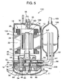
- FIG. 5 shows a vertically sectional side view of an inner high pressure type rotary compressor 110 comprising first and second rotary compression elements, which is a multicylinder rotary compressor of the compression system CS in this embodiment. It is to be noted that, in FIG. 5, when components are denoted with the same reference numerals as those of FIGS. 1 to 4, the components produce the same or similar effects.
- reference numeral 200 denotes a valve device, and the device is disposed in a middle portion of a refrigerant introducing tube 94 on an inlet side of the sealed container 12 on an outlet side of an accumulator 146.
- This electromagnetic valve 200 is a valve device for controlling flowing of a refrigerant into a second cylinder 40, and is controlled by the above-described controller 210 which is a control device.
- an HFC or HC-based refrigerant is used as a refrigerant in the same manner as in the above-described embodiment.
- oils which are lubricants existing oils are used such as a mineral oil, an alkyl benzene oil, an ether oil, and an ester oil.
- the controller 210 controls a rotation number of an electromotive element 14 of the rotary compressor 110 based on an operation instruction input of an indoor-unit-side controller (not shown) disposed in the above-described indoor unit. Moreover, in a usual or high load indoor state, the controller 210 executes the first operation mode. In this first operation mode, the controller 210 opens the electromagnetic valve 200 of the refrigerant introducing pipe 94, and closes an electromagnetic valve 105 of a refrigerant pipe 101, and an electromagnetic valve 106 of a refrigerant pipe 102.
- first and second rollers 46, 48 are fitted into upper and lower eccentric portions 42, 44 integrally disposed in a rotation shaft 16, and eccentrically rotate in first and second cylinders 38, 40.
- a low-pressure refrigerant flows into the accumulator 146 from a refrigerant pipe 100 of the rotary compressor 110. Since the electromagnetic valve 105 of the refrigerant pipe 100 is closed as described above, all the refrigerant passed through the refrigerant pipe 100 flows into the accumulator 146 without flowing into a pipe 75.
- the low-pressure refrigerant which has flown into the accumulator 146 is separated into gas/liquid, and thereafter the only refrigerant gas enters refrigerant discharge tubes 92, 94 which open in the accumulator 146.
- the low-pressure refrigerant gas which has entered the refrigerant introducing tube 92 is passed through a suction passage 58, and sucked on a low-pressure chamber side of the first cylinder 38 of the first rotary compression element 32.
- the refrigerant gas sucked on the low-pressure chamber side of the first cylinder 38 is compressed by the operations of a first roller 46 and a first vane 50 to constitute a high-temperature/pressure refrigerant gas.
- the gas flows through a discharge port (not shown) from the high-pressure chamber side of the first cylinder 38, and is discharged to a discharge muffling chamber 62.
- the low-pressure refrigerant gas which has flown into the refrigerant introducing tube 94 is passed through a suction passage 60, and sucked on the low-pressure chamber side of the second cylinder 40 of the second rotary compression element 34.
- the refrigerant gas sucked on the low-pressure chamber side of the second cylinder 40 is compressed by the operations of the second roller 48 and a second vane 52.
- a pressure in the back-pressure chamber 72A of the second vane 52 is an intermediate pressure between the suction-side and discharge-side pressures of both the rotary compression elements 32, 34, and the intermediate pressure is applied as the back pressure of the second vane 52.
- the second vane 52 can be sufficiently urged toward the second roller 48 without using any spring member.
- the refrigerant gas is compressed by the operations of the second roller 48 and second vane 52 to obtain a high-temperature/pressure.
- the gas is passed through a discharge port (not shown) from the high-pressure chamber side of the second cylinder 40, and is discharged to the discharge muffling chamber 64.
- the refrigerant gas discharged to the discharge muffling chamber 64 is discharged to the discharge muffling chamber 62 via the communication path 120, and flows together with the refrigerant gas compressed by the first rotary compression element 32.
- the joined refrigerant gas is discharged into the sealed container 12 from a hole (not shown) extending through the cup member 63.
- the refrigerant in the sealed container 12 is discharged to the outside from the refrigerant discharge tube 96 formed in the end cap 12B of the sealed container 12, and flows into the outdoor heat exchanger 152.
- the refrigerant gas emits heat
- pressure of the gas is reduced by an expansion valve 154
- the gas flows into an indoor heat exchanger 156.
- the indoor heat exchanger 156 the refrigerant evaporates, the heat is absorbed from air circulated in the room to thereby exert a cooling function, and the inside of the room is cooled.
- the refrigerant emanates from the indoor heat exchanger 156 and is sucked by the rotary compressor 110. The refrigerant repeats this cycle.
- the controller 210 shifts to a second operation mode from the first operation mode.
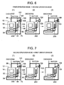
- a switching operation will be described from the first operation mode to the second operation mode with reference to FIG. 6. It is to be noted that at a mode switching time, the controller 210 rotates the electromotive element 14 at a low speed, a rotation number is set, for example, to 50 Hz or less, and a compression ratio of the rotary compression element 32 is controlled into 3.0 or less.
- the controller 210 closes the above-described electromagnetic valve 200, and interrupts the flowing of the refrigerant into the second cylinder 40 (FIG. 6 (2)). Accordingly, any compression work is not performed in the second rotary compression element 34.
- a pressure in the second cylinder 40 is slightly higher than a suction-side pressure of both the rotary compression elements 32, 34 (the second roller 48 rotates, a high pressure in the sealed container 12 slightly flows from a gap of the second cylinder 40 or the like, and therefore the pressure in the second cylinder 40 becomes slightly higher than the suction-side pressure).
- the pressure in the back-pressure chamber 72A is an intermediate pressure between the suction-side and discharge-side pressures of both the rotary compression elements 32, 34 as described above. Therefore, the pressure in the second cylinder 40 is substantially equal to that in the back-pressure chamber 72A of the second vane 52.
- the controller 210 opens the electromagnetic valve 105 of the refrigerant pipe 101. It is to be noted that the electromagnetic valve 106 of the refrigerant pipe 102 remains to be closed (FIG. 6 (3)). Accordingly, the refrigerant pipe 101 communicates with the pipe 75, the suction-side refrigerant of the first rotary compression element 32 flows into the back-pressure chamber 72A, and the suction-side pressure of the first rotary compression element 32 is applied as the back pressure of the second vane 52.
- the refrigerant passes through the refrigerant pipe 100 on the suction side of the first rotary compression element 32, and a part of the refrigerant flows into the back-pressure chamber 72A from the refrigerant pipe 101 via the pipe 75.
- the back-pressure chamber 72A has a suction-side pressure of the first rotary compression element 32, and the suction-side pressure of the first rotary compression element 32 is applied as the back pressure of the second vane 52.
- the pressure of the second cylinder 40 is higher than the suction-side pressure of the first rotary compression element 32. Therefore, when the suction-side pressure of the first rotary compression element 32 is applied as the back pressure of the second vane 52, the pressure in the back-pressure chamber 72A of the second vane 52 is higher than that of the second cylinder 40. Therefore, the second vane 52 is pushed toward the back-pressure chamber 72A on a side opposite to the second roller 48 by the pressure in the second cylinder 40, and housed in the guide groove 72. Consequently, at the switching time to the second operation mode, the second vane 52 can be retracted from the inside of the second cylinder 40, and housed in the guide groove 72 in an early stage. Therefore, it is possible to avoid beforehand a disadvantage that the second vane 52 collides with the second roller 48, and the collision sound is generated.
- the low-pressure refrigerant flows into the accumulator 146 from the refrigerant pipe 100 of the rotary compressor 110. After the refrigerant is separated into the gas/liquid in the accumulator, the only refrigerant gas enters the refrigerant discharge tube 92 which opens in the accumulator 146.
- the low-pressure refrigerant gas which has entered the refrigerant introducing tube 92 flows through the suction passage 58, and is sucked on the low-pressure chamber side of the first cylinder 38 of the first rotary compression element 32.
- the refrigerant gas sucked on the low-pressure chamber side of the first cylinder 38 is compressed by the operations of the first roller 46 and the first vane 50 to constitute a high-temperature/pressure refrigerant gas.
- the gas is discharged to the discharge muffling chamber 62 from the high-pressure chamber side of the first cylinder 38 through a discharge port (not shown).
- the refrigerant gas discharged to the discharge muffling chamber 62 is discharged into the sealed container 12 from a hole (not shown) extending through the cup member 63.
- the refrigerant in the sealed container 12 is discharged to the outside from the refrigerant discharge tube 96 formed in the end cap 12B of the sealed container 12, and flows into the outdoor heat exchanger 152.
- the refrigerant gas emits heat.
- the gas flows into the indoor heat exchanger 156.
- the refrigerant evaporates.
- the heat is absorbed from air circulated in the room to exert a cooling function, and the inside of the room is cooled.
- the refrigerant emanates from the indoor heat exchanger 156 and is sucked into the rotary compressor 110, and this cycle is repeated.
- the controller 210 closes the above-described electromagnetic valve 200.
- the operation is performed while stopping the flowing of the refrigerant into the second cylinder 40.
- the pressure in the second cylinder 40 is kept to be higher than the back pressure of the second vane 52. Therefore, the second vane 52 is pushed toward the back-pressure chamber 72A opposite to the second roller 48 by the pressure in the second cylinder 40, and the vane does not come into the second cylinder 40. Consequently, it is possible to avoid beforehand a disadvantage that the second vane 52 comes into the second cylinder 40 during the operation in the second operation mode, the vane collides with the second roller 48, and the collision sound is generated.
- the controller 210 shifts from the second operation mode to the first operation mode.
- an operation will be described in switching the second operation mode to the first operation mode with reference to FIG. 7.
- the controller 210 opens the electromagnetic valve 200 and allows the refrigerant to flow into the second cylinder 40.
- the controller closes the electromagnetic valve 105 of the refrigerant pipe 101, and opens the electromagnetic valve 106 of the refrigerant pipe 102 (FIG. 7 (2)).
- the refrigerant pipe 102 communicates with the pipe 75, discharge-side refrigerants of both the rotary compression elements 32, 34 flow into the back-pressure chamber 72A, and the discharge-side pressures of both the rotary compression elements 32, 34 are applied as the back pressure of the second vane 52.
- the back-pressure chamber of the second vane 52 has a pressure which is remarkably higher than that inside the second cylinder 40. Therefore, the second vane 52 is pushed toward the second roller 48 to follow up the roller by the high pressure of the back-pressure chamber 72A.
- the second vane 52 can be sufficiently pushed out on the side of the second roller. That is, when the second operation mode shifts to the first operation mode, the intermediate pressure is applied as the back pressure of the second vane 52 as in the above-described usual operation time in the first operation mode.
- the intermediate pressure is between the suction-side and discharge-side pressures of both the rotary compression elements 32, 34. At this intermediate pressure, a pressure difference is small between the inside of the second cylinder 40 and the back-pressure chamber 72A. Therefore, much time is required for the second vane 52 to follow up the second roller 48. During this time, a disadvantage has occurred that the second vane 52 collides with the second roller 48, and the collision sound is generated.
- the discharge-side pressures of both the rotary compression elements 32, 34 are applied as the back pressure of the second vane 52 at the switching time from the second operation mode to the first operation mode. Accordingly, the second vane 52 is sufficiently urged toward the second roller 48 by the discharge-side pressure, and the second roller 48 can follow up in an early stage.
- the controller 210 rotates the electromotive element 14 at a low speed (rotation number of 50 Hz or less), and controls the compression ratio of both the rotary compression elements 32, 34 into 3.0 or less. Accordingly, since a pressure fluctuation can be suppressed, an influence is not easily exerted by the pressure fluctuation even in a case where the discharge-side pressures of both the rotary compression elements 32, 34 are applied as the back pressure of the second rotary compression element 34.
- the controller 210 applies the discharge-side pressures of both the rotary compression elements 32, 34 to the second vane 52. After the second vane 52 follows up the second roller 48, the controller closes the electromagnetic valve 106 (FIG. 7 (3)), and applies the intermediate pressure between the suction-side and discharge-side pressures of both the rotary compression elements 32, 34. Accordingly, the pressure fluctuation is remarkably reduced as compared with the application of the discharge-side pressures of both the rotary compression elements 32, 34 to the back pressure of the second vane 52 as described above.
- the follow-up property of the second vane 52 is improved, the compression efficiency of the second rotary compression element 34 is improved, and it is possible to avoid beforehand the generation of the collision sound between the second vane 52 and the second roller 48 in the first operation mode.
- the system comprises the rotary compressor 110 which is usable by the switching of the first operation mode in which the first and second rotary compression elements 32,34 perform the compression work and the second operation mode in which the only first rotary compression element 32 substantially performs the compression work.
- an electromagnetic valve 200 is disposed in a middle portion of a refrigerant introducing tube 94 on an inlet side of a sealed container 12 on an outlet side of an accumulator 146 as shown in FIG. 5 of Embodiment 2, and the electromagnetic valve 200 may be controlled by a controller 210.
- the electromagnetic valve 200 When the electromagnetic valve 200 is disposed in the refrigerant introducing tube 94 in this manner, the electromagnetic valve is closed at a starting time, flowing of a refrigerant into a second rotary compression element 34 is completely interrupted, an electromagnetic valve 106 of a refrigerant pipe 102 is opened, and the electromagnetic valve 200 is opened. Even in this case, the present invention is effective.
- the system is operated in a state in which the controller 210 closes the electromagnetic valve 200 to stop the flowing of the refrigerant into a second cylinder 40 in a second operation mode. Accordingly, a pressure inside the second cylinder 40 can be set to be higher than a suction-side pressure of a first rotary compression element 32.
- an HFC or HC-based refrigerant is used as a refrigerant in the same manner as in the above-described embodiments.
- oils which are lubricants existing oils are used such as a mineral oil, an alkyl benzene oil, an ether oil, and an ester oil.
- the controller 210 closes the above-described electromagnetic valve 200 to stop the flowing of the refrigerant into the second cylinder 40. Accordingly, any compression work is not performed in the second rotary compression element 34.
- the pressure in the second cylinder 40 is slightly higher than the suction-side pressures of both the rotary compression elements 32, 34 (since a second roller 48 rotates, and a high pressure in the sealed container 12 slightly flows via a gap of the second cylinder 40, the pressure in the second cylinder 40 becomes slightly higher than the suction-side pressure).
- the controller 210 opens an electromagnetic valve 105 of a refrigerant pipe 101, and closes an electromagnetic valve 106 of a refrigerant pipe 102. Accordingly, the refrigerant pipe 101 communicates with a pipe 75, the suction-side refrigerant of the first rotary compression element 32 flows into a back-pressure chamber 72A, and the suction-side pressure of the first rotary compression element 32 is applied as a back pressure of a second vane 52.
- the refrigerant passes through a refrigerant pipe 100 of a rotary compressor 110 on a suction side of the first rotary compression element 32, and a part of the refrigerant flows into a back-pressure chamber 72A from the refrigerant pipe 101 via a pipe 75.
- the back-pressure chamber 72A has the suction-side pressure of the first rotary compression element 32, and the suction-side pressure of the first rotary compression element 32 is applied as the back pressure of the second vane 52.
- the electromagnetic valve 200 is closed to stop the flowing of the refrigerant into the second cylinder 40, and the pressure in the second cylinder 40 is set to be higher than the suction-side pressure of the first rotary compression element 32.
- the suction-side pressure of the first rotary compression element 32 is applied as the back pressure of the second vane 52
- the pressure in the second cylinder 40 becomes higher than the back pressure of the second vane 52. Therefore, the second vane 52 is pushed toward the back-pressure chamber 72A opposite to the second roller 48 by the pressure in the second cylinder 40, and the vane does not come into the second cylinder 40. Consequently, it is possible to avoid beforehand a disadvantage that the second vane 52 comes into the second cylinder 40 to collide with the second roller 48, and a collision sound is generated.
- the low-pressure refrigerant which has flown into the accumulator 146 is separated into gas/liquid in the accumulator. Thereafter, an only refrigerant gas enters a refrigerant introducing tube 92 which opens in the accumulator 146.
- the low-pressure refrigerant gas which has entered the refrigerant introducing tube 92 is sucked on a low-pressure chamber side of a first cylinder 38 of the first rotary compression element 32 via a suction passage 58.
- the refrigerant gas sucked on the low-pressure chamber side of the first cylinder 38 is compressed by operations of the first roller 46 and a first vane 50 to constitute a high-temperature/pressure refrigerant gas.
- the gas passes through a discharge port (not shown) from a high-pressure chamber side of the first cylinder 38, and is discharged to a discharge muffling chamber 62.
- the refrigerant gas discharged to the discharge muffling chamber 62 is discharged into the sealed container 12 from a hole (not shown) extending through a cup member 63.
- the refrigerant in the sealed container 12 is discharged to the outside from a refrigerant discharge tube 96 formed in an end cap 12B of the sealed container 12, and flows into an outdoor heat exchanger 152.
- the refrigerant gas emits heat in the exchanger, the pressure of the gas is reduced by an expansion valve 154, and thereafter the gas flows into an indoor heat exchanger 156.
- the refrigerant evaporates in the indoor heat exchanger 156, the heat is absorbed from air circulated in a room to thereby exert a cooling function, and the inside of the room is cooled.
- the refrigerant emanates from the indoor heat exchanger 156 and is sucked by the rotary compressor 110. The refrigerant repeats this cycle.
- the electromagnetic valve 200 is disposed in the middle portion of the refrigerant introducing tube 94, and the compressor is operated in a state in which the controller 210 closes the electromagnetic valve 200 to stop the flowing of the refrigerant into the second cylinder 40 in the second operation mode. Accordingly, in the second operation mode, the pressure in the second cylinder 40 is kept to be higher than the back pressure of the second vane 52. Therefore, the second vane 52 is pushed toward the back-pressure chamber 72A opposite to the second roller 48 by the pressure in the second cylinder 40, and the vane does not come into the second cylinder 40. Consequently, it is possible to avoid beforehand the disadvantage that the second vane 52 comes into the second cylinder 40 to collide with the second roller 48, and the collision sound is generated during the operation in the second operation mode.
- the system comprises the rotary compressor 110 which is usable by the switching of the first operation mode in which the first and second rotary compression elements 32, 34 perform the compression work and the second operation mode in which the only first rotary compression element 32 substantially performs the compression work.
- Figure 8 is a vertically sectional side view of the multicylinder rotary compressor according to the present invention in this case.
- Another vertically sectional side view of the multicylinder rotary compressor of the present embodiment is the same as Figure 1 of embodiment 1, and a refrigerant circuit diagram is also the same as Figure 3. Therefore, an only constitution different from that of embodiment 1 will be described in the present embodiment. It is to be noted that in the present embodiment, components denoted with the same reference numerals as those of Figures 1 to 3 produce the same or similar effects.
- a back-pressure chamber 172A opens on the sides of a guide groove 72 and a sealed container 12, a pipe 75 described later communicates with/is connected to an opening on the sealed container 12 side, and the pipe is sealed together with the inside of the sealed container 12.
- the back pressure chamber 172A of the present invention is constituted as a muffler chamber having a predetermined space volume.
- the back-pressure chamber 172A of the embodiment has a shape in which a concavely depressed chamber having the predetermined space volume is disposed in a position constituting a connection portion of the pipe 75 to the guide groove 72 on a lower support member 56. That is, the back-pressure chamber 172A of the present embodiment is formed by a concavely depressed portion formed in a position corresponding to the pipe 75 and the guide groove 72 on the upper surface of the lower support member 56 which closes an opening face under a second cylinder 40. In the depressed portion, an opening in the lower surface of the second cylinder 40 is closed by the lower support member 56.
- the back-pressure chamber 172A When the back-pressure chamber 172A is formed in such a manner as to have the predetermined space volume ad described above, the back-pressure chamber 172A can reduce pressure pulsation caused by an urging operation of a second vane 52, and pulsation of a pressure applied as a back pressure of the second vane 52.
- oils which are lubricants existing oils are used such as a mineral oil, an alkyl benzene oil, an ether oil, and an ester oil.
- a controller 210 controls a rotation number of an electromotive element 14 of the rotary compressor 10 based on an operation instruction input of an indoor-unit-side controller (not shown) disposed in the above-described indoor unit. Moreover, in a usual or high load indoor state, the controller 210 executes the first operation mode. In this first operation mode, the controller 210 closes an electromagnetic valve 105 of a refrigerant pipe 101 and opens an electromagnetic valve 106 of a refrigerant pipe 102.
- the refrigerant pipe 102 communicates with the pipe 75, suction-side refrigerants of both the rotary compression elements 32, 34 flow into the back-pressure chamber 172A, and suction-side pressures of both the rotary compression elements 32, 34 are applied as a back pressure of the second vane 52.
- first and second rollers 46, 48 are fitted into upper and lower eccentric portions 42, 44 integrally disposed in a rotation shaft 16, and eccentrically rotate in first and second cylinders 38, 40.
- a low-pressure refrigerant flows into an accumulator 146 from a refrigerant pipe 100 of the rotary compressor 10. Since the electromagnetic valve 105 of the refrigerant pipe 100 is closed as described above, all the refrigerant passed through the refrigerant pipe 100 flows into the accumulator 146 without flowing into the pipe 75.
- the low-pressure refrigerant which has flown into the accumulator 146 is separated into gas/liquid, and thereafter the only refrigerant gas enters refrigerant discharge tubes 92, 94 which open in the accumulator 146.
- the low-pressure refrigerant gas which has entered the refrigerant introducing tube 92 is sucked on a low-pressure chamber side of the first cylinder 38 of the first rotary compression element 32 via a suction passage 58.
- the refrigerant gas sucked on the low-pressure chamber side of the first cylinder 38 is compressed by the operations of the first roller 46 and a first vane 50 to constitute a high-temperature/pressure refrigerant gas.
- the gas is passed through a discharge port (not shown) from the high-pressure chamber side of the first cylinder 38, and is discharged to a discharge muffling chamber 62.
- the low-pressure refrigerant gas which has flown into the refrigerant introducing tube 94 is passed through a suction passage 60, and sucked on the low-pressure chamber side of the second cylinder 40 of the second rotary compression element 34.
- the refrigerant gas sucked on the low-pressure chamber side of the second cylinder 40 is compressed by the operations of the second roller 48 and the second vane 52.
- the back-pressure chamber 172A is formed into the muffler chamber having the predetermined space volume as in the present invention, it is possible to reduce the pressure pulsation generated by the urging operation of the second vane 52.
- the pressure pulsation is remarkably reduced in a process in which the refrigerants pass through the back-pressure chamber 172A. Accordingly, the second vane 52 can be sufficiently urged toward the second roller 48 without using any spring member.
- the follow-up property of the second vane 52 is improved in the first operation mode, and the compression efficiency of the second rotary compression element 34 is enhanced. Furthermore, since the follow-up property of the second vane 52 is improved, it is possible to avoid the collision with the second roller 48. Therefore, it is possible to avoid as much as possible the disadvantage that the collision sound is generated between the second vane and the second roller 48.
- the refrigerant gas is compressed by the operations of the second roller 48 and second vane 52 to obtain a high-temperature/pressure.
- the gas is passed through a discharge port (not shown) from the high-pressure chamber side of the second cylinder 40, and is discharged to a discharge muffling chamber 64.
- the refrigerant gas discharged to the discharge muffling chamber 64 is discharged to the discharge muffling chamber 62 via a communication path 120, and flows together with the refrigerant gas compressed by the first rotary compression element 32.
- the joined refrigerant gas is discharged into a sealed container 12 from a hole (not shown) extending through a cup member 63.
- the refrigerant in the sealed container 12 is discharged to the outside from a refrigerant discharge tube 96 formed in an end cap 12B of the sealed container 12, and flows into an outdoor heat exchanger 152.
- the electromagnetic valve 106 is opened by the controller 210 as described above, a part of the discharge-side refrigerant flows into the back-pressure chamber 172A from the refrigerant pipe 102 via the pipe 75.
- the discharge-side refrigerants of both the rotary compression elements 32, 34 flow through the refrigerant discharge tube 96. Accordingly, the discharge-side pressures of both the rotary compression elements 32, 34 are applied as the back pressure of the second vane 52.
- the refrigerant gas which has flown into the outdoor heat exchanger 152 emits heat in the exchanger, the pressure of the gas is reduced by an expansion valve 154, and thereafter the gas flows into an indoor heat exchanger 156.
- the refrigerant evaporates in the indoor heat exchanger 156, the heat is absorbed from air circulated in the room to thereby exert a cooling function, and the inside of the room is cooled.
- the refrigerant emanates from the indoor heat exchanger 156 and is sucked by the rotary compressor 10. The refrigerant repeats this cycle.
- the controller 210 closes the electromagnetic valve 105 of the refrigerant pipe 101, and opens the electromagnetic valve 106 of the refrigerant pipe 102 in such a manner that the refrigerant pipe 102 communicates with the pipe 75.
- the discharge-side pressures of both the rotary compression elements 32, 34 are high pressures, and are applied as the back pressure of the second vane 52.
- an intermediate pressure may be applied as the back pressure of the second vane 52 in the first operation mode, and the intermediate pressure is between the suction-side and discharge-side pressures of both the rotary compression elements 32, 34.
- the controller 210 closes the electromagnetic valve 105 of the refrigerant pipe 101 and the electromagnetic valve 106 of the refrigerant pipe 102 to form a closed space inside the pipe 75 connected to the back-pressure chamber 172A of the second vane 52. Then, not a little refrigerant in the second cylinder 40 flows into the back-pressure chamber 172A between the second vane 52 and the housing section 70A. Therefore, the pressure in the back-pressure chamber 172A of the second vane 52 constitutes the intermediate pressure between the suction-side and discharge-side pressures of both the rotary compression elements 32, 34, and this intermediate pressure is applied as the back pressure of the second vane 52.
- the second vane 52 can be sufficiently urged toward the second roller 48 by the intermediate pressure without using any spring member. Furthermore, the pressure pulsation is remarkably reduced as compared with the application of the discharge-side pressures of both the rotary compression elements 32, 34. Therefore, in addition to a pulsation reducing effect by the back-pressure chamber 172A, the pulsation can further be reduced. Especially, when the electromagnetic valves 105, 106 are closed as described above to interrupt the flowing of the suction-side and discharge-side refrigerants of both the rotary compression elements 32, 34 from the pipe 75, the pulsation of the back pressure of the second vane 52 can be further suppressed.
- the controller 210 shifts to the second operation mode.
- the only first rotary compression element 32 substantially performs a compression work.
- the operation mode is performed in a case where the inside of the room has a light load and the electromotive element 14 rotates at a low speed in the first operation mode.
- an amount of the refrigerant gas to be compressed can be reduced as compared with a case where the first and second cylinders 38, 40 perform the compression work. Therefore, the rotation number of the electromotive element 14 is raised also at the light load time by the corresponding amount, the operation efficiency of the electromotive element 14 is improved, and a leak loss of the refrigerant can be reduced.
- the controller 210 opens the electromagnetic valve 105 of the refrigerant pipe 101, and closes the electromagnetic valve 106 of the refrigerant pipe 102. Accordingly, the refrigerant pipe 101 communicates with the pipe 75, a suction-side refrigerant of the first rotary compression element 32 flows into the back-pressure chamber 172A, and the suction-side pressure of the first rotary compression element 32 is applied as the back pressure of the second vane 52.
- the controller 210 energizes the stator coil 28 of the electromotive element 14 via the terminal 20 and the wiring (not shown), and rotates the rotor 24 of the electromotive element 14 as described above.
- the first and second rollers 46, 48 are fitted into the upper and lower eccentric portions 42, 44 disposed integrally with the rotation shaft 16, and eccentrically rotate in the first and second cylinders 38, 40.
- the low-pressure refrigerant flows into the accumulator 146 from the refrigerant pipe 100 of the rotary compressor 10. Since the electromagnetic valve 105 of the refrigerant pipe 101 opens at this time as described above, a part of the refrigerant on the suction side of the first rotary compression element 32 passes through the refrigerant pipe 100, and flows into the back-pressure chamber 172A from the refrigerant pipe 101 via the pipe 75. Accordingly, the back-pressure chamber 172A has a suction-side pressure of the first rotary compression element 32, and the suction-side pressure of the first rotary compression element 32 is applied as the back pressure of the second vane 52.
- the suction-side pressures of both the rotary compression elements 32, 34 are applied as the back pressure of the second rotary compression element 34, and this pressure is a low pressure. Therefore, the second vane 52 cannot be urged toward the second roller 48. Therefore, the compression work is not substantially performed in the second rotary compression element 34, and the compression work of the refrigerant is performed only by the first rotary compression element 32 provided with the spring 74.
- the low-pressure refrigerant which has flown into the accumulator 146 is separated into gas/liquid, and thereafter the refrigerant gas only enters the refrigerant discharge tube 92 which opens in the accumulator 146.
- the low-pressure refrigerant gas which has entered the refrigerant introducing tube 92 flows through the suction passage 58, and is sucked on the low-pressure chamber side of the first cylinder 38 of the first rotary compression element 32.
- the refrigerant gas sucked on the low-pressure chamber side of the first cylinder 38 is compressed by the operations of the first roller 46 and the first vane 50 to constitute a high-temperature/pressure refrigerant gas, and the gas is discharged to the discharge muffling chamber 62 from the high-pressure chamber side of the first cylinder 38 through a discharge port (not shown).
- the refrigerant gas discharged to the discharge muffling chamber 62 is discharged into the sealed container 12 from a hole (not shown) extending through the cup member 63.
- the refrigerant in the sealed container 12 is discharged to the outside from the refrigerant discharge tube 96 formed in the end cap 12B of the sealed container 12, and flows into the outdoor heat exchanger 152. There, the refrigerant gas emits heat. After the pressure of the gas is reduced by the expansion valve 154, the gas flows into the indoor heat exchanger 156. The refrigerant evaporates in the indoor heat exchanger 156, the heat is absorbed from air circulated in the room to thereby exert a cooling function, and the inside of the room is cooled. Moreover, the refrigerant emanates from the indoor heat exchanger 156 and is sucked by the rotary compressor 10. The refrigerant repeats this cycle.
- the performance and reliability of the rotary compressor 10 can be enhanced.
- the compressor is usable by the switching of the first operation mode in which the first and second rotary compression elements 32,34 perform the compression work and the second operation mode in which the only first rotary compression element 32 substantially performs the compression work.
- a back-pressure chamber 172A is formed into a shape having a concavely depressed chamber having a predetermined space volume, but the present invention is not limited to this embodiment, and the back-pressure chamber of the present invention is not limited as long as the chamber has a predetermined space volume.
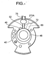
- the present invention is also effective, for example, in a case where the back-pressure chamber has a shape shown in Figure 9. It is to be noted that Figure 9 is a flat sectional view of a second cylinder in this case. In Figure 9, components denoted with the same reference numerals as those of Figures 1 to 8 produce the same or similar effects.
- reference numeral 49 denotes a discharge port of the second rotary compression element 34.
- a back-pressure chamber 272A of the present embodiment has an expande3d portion having a predetermined space volume in a transverse direction of a second cylinder 40 and entirely has a substantially cylindrical shape. Even when the back-pressure chamber 272A is formed into the shape of the present embodiment in this manner, the back-pressure chamber 272A can reduce pressure pulsation, improve a follow-up property of a second vane 52, and avoid collision with a second roller 48.
- an electromagnetic valve 200 is disposed in a middle portion of a refrigerant introducing tube 94 on an inlet side of a sealed container 12 on an outlet side of an accumulator 146 of a rotary compressor 10 in such a manner as to control flowing of a refrigerant into a second rotary compression element 34.
- the electromagnetic valve 200 may be closed to interrupt the flowing of the refrigerant into a second cylinder 40.
- a pressure in the second cylinder 40 is slightly higher than a suction-side pressure of both the rotary compression elements 32,34 (the second roller 48 rotates, a high pressure in the sealed container 12 slightly flows from a gap of the second cylinder 40 or the like, and therefore the pressure in the second cylinder 40 becomes slightly higher than the suction-side pressure).
- the second vane 52 is pushed toward a back-pressure chamber 172A (or the back-pressure chamber 272A) opposite to the second roller 48, and does not come into the second cylinder 40 by the pressure in the second cylinder 40. Therefore, in addition to the above-described effect of the back-pressure chamber 172A (or the back-pressure chamber 272A), it is possible to avoid more effectively a disadvantage that the second vane 52 collides with the second roller 48.
- the two-air-cylinder rotary compressor has been used, but the present invention may be adapted to a compression system comprising a multicylinder rotary compressor comprising three air cylinders or more rotary compression elements.
Landscapes
- Engineering & Computer Science (AREA)
- Mechanical Engineering (AREA)
- General Engineering & Computer Science (AREA)
- Applications Or Details Of Rotary Compressors (AREA)
- On-Site Construction Work That Accompanies The Preparation And Application Of Concrete (AREA)
- Manufacture, Treatment Of Glass Fibers (AREA)
- Diaphragms For Electromechanical Transducers (AREA)
Claims (6)
- Verfahren zur Steuerung eines Kompressionssystems zur Verdichtung von Kältemittel, umfassend einen Rotationskompressor mit mehreren Zylindern, mit ersten und zweiten Rotationskompressionselementen (32, 34) und mit einer Kontrolleinheit (210), die derart konfiguriert ist, dass sie einen Gegendruck des Kältemittels kontrolliert, der an das zweite Rotationskompressionselement (34) angelegt wird, so dass der Kompressor zwischen einem ersten Modus, in dem sowohl das erste als auch das zweite Rotationskompressionselement (32, 34) betrieben werden und der Gegendruck, der an das zweite Rotationskompressionselement (34) angelegt wird, ein mittlerer Druck ist, zwischen dem Druck des Kältemittels, das in den Kompressor eintritt und dem Druck des Kältemittels, welches dem Kompressor verläßt, und einem zweiten Modus umschaltet, in dem nur das erste Rotationskompressionselement (32) betrieben wird und in dem der Gegendruck, der an das zweite Rotationskompressionselement (34) angelegt wird, der Druck des Kältemittels ist, welches in den Kompressor eintritt, wobei das Verfahren den Schritt des Betreibens des Kompressors in einem Zwischenmodus umfasst, in dem die Kontrolleinheit (210) den Kompressor von dem zweiten in den ersten Modus umschaltet, so dass der Gegendruck, der auf das zweite Rotationskompressionselement (34) einwirkt, der Ausleitungsdruck des Kältemittels ist, welches durch beide Rotationskompressionselemente (32, 34) verdichtet worden ist.
- Verfahren zur Steuerung eines Kompressionssystems nach Anspruch 1, mit einem Kältemittelströmungssteuerventil (106), um die Strömung an Kältemittel in das zweite Rotationskompressionselement (34) zu steuern, wobei das Verfahren weiterhin die Schritte des Schließens des Ventils (106), um das Einströmen von Kältemittel in das zweite Rotationskompressionselement (34) zu vermeiden, wenn das Kompressionssystem von dem ersten in den zweiten Modus umgeschaltet wird, sowie das Öffnen des Ventils (106) umfasst, um das Einströmen von Kältemittel in das zweite Rotationskompressionselement (34) zu ermöglichen, wenn das Kompressionssystem von dem zweiten in den ersten Modus umgeschaltet wird.
- Verfahren zur Steuerung eines Kompressionssystems nach Anspruch 1 oder 2, wobei das Verfahren weiterhin den Schritt umfasst, dass der Kompressor in dem zweiten Modus betrieben wird, in dem nur das erste Rotationskompressionselement (32) betreibbar ist und in dem der Gegendruck, der an das zweite Rotationskompressionselement (34) angelegt wird, der Druck des Kältemittels ist, welches in den Kompressor eintritt, während einer vorbestimmten Zeitspanne nach dem Starten des Kompressors.
- Verfahren zur Steuerung eines Kompressionssystems nach Anspruch 1, wobei das Verfahren weiterhin den Schritt des Umschaltens des Kompressors in den Zwischenmodus umfasst, in dem der Gegendruck, der auf das zweite Rotationskompressionselement (34) einwirkt, der Ausleitungsdruck des Kältemittels ist, welches von sowohl dem ersten als auch dem zweiten Kompressionselement (32, 34) verdichtet worden ist, nachdem die vorbestimmte Zeitspanne verstrichen ist und bevor der Kompressor in den ersten Modus umgeschaltet wird, in dem sowohl das erste als auch das zweite Rotationskompressionselement (32 ,34) betreibbar sind und der Gegendruck, der an das zweite Rotationskompressionselement (34) angelegt wird, ein mittlerer Druck ist, der zwischen dem Druck des Kältemittels, welches in den Kompressor eintritt und dem Druck des Kältemittels liegt, welches den Kompressor verläßt
- Verfahren zur Steuerung eines Kompressionssystems nach Anspruch 1 bis 4, wobei der Rotationskompressor mit mehreren Zylindern weiterhin ein Antriebselement (14) umfasst, wobei das Verfahren weiterhin den Schritt des Betreibens des Antriebselements (14) mit niedriger Drehzahl umfasst sowie Festsetzen eines Verdichtungsverhältnisses des ersten Rotationskompressionselements (32) oder beider Rotationskompressionselemente (32, 34) auf 3,0 oder weniger, wenn der Modus umgeschaltet wird.
- Kompressionssystem zum Verdichten von Kältemittel, mit einem Rotationskompressor mit mehreren Zylindern, mit ersten und zweiten Rotationskompressionselementen (32, 34) und mit einer Kontrolleinheit (210), die derart konfiguriert ist, dass sie einen Gegendruck des Kältemittels kontrolliert, der an das zweite Rotationskompressionselement (34) angelegt wird, so dass der Kompressor zwischen einem ersten Modus, in dem sowohl das erste als auch das zweite Rotationskompressionselement (32, 34) betreibbar sind und der Gegendruck, der an das zweite Rotationskompressionselement (34) angelegt wird, ein mittlerer Druck ist, zwischen dem Druck des Kältemittels, das in den Kompressor eintritt und dem Druck des Kältemittels, welches dem Kompressor verläßt, und einem zweiten Modus umgeschaltet wird, in dem nur das erste Rotationskompressionselement (32) betrieben wird und in dem der Gegendruck, der an das zweite Rotationskompressionselement (34) angelegt wird, der Druck des Kältemittels ist, welches in den Kompressor eintritt, wobei die Kontrolleinheit (210) auch derart konfiguriert ist, dass sie den Kompressor in einem Zwischenmodus betreibt, wenn der Kompressor von dem zweiten Modus in den ersten Modus umgeschaltet wird, in dem der Gegendruck, der auf das zweite Rotationskompressionselement (34) einwirkt, der Ausleitungsdruck des Kältemittels ist, welches durch beide Rotationskompressionselemente (32, 34) verdichtet worden ist.
Priority Applications (1)
| Application Number | Priority Date | Filing Date | Title |
|---|---|---|---|
| EP20070003079 EP1813814A3 (de) | 2004-07-08 | 2005-07-08 | Kompressionssystem |
Applications Claiming Priority (5)
| Application Number | Priority Date | Filing Date | Title |
|---|---|---|---|
| JP2004201915A JP4404708B2 (ja) | 2004-07-08 | 2004-07-08 | 圧縮システム及びそれを用いた冷凍装置 |
| JP2004201601A JP2006022723A (ja) | 2004-07-08 | 2004-07-08 | 圧縮システム及びそれを用いた冷凍装置 |
| JP2004203001A JP2006022766A (ja) | 2004-07-09 | 2004-07-09 | 多気筒回転圧縮機 |
| JP2004202994A JP4726444B2 (ja) | 2004-07-09 | 2004-07-09 | 多気筒回転圧縮機 |
| JP2004235419A JP2006052693A (ja) | 2004-08-12 | 2004-08-12 | 多気筒回転圧縮機及びそれを用いた圧縮システム |
Related Child Applications (1)
| Application Number | Title | Priority Date | Filing Date |
|---|---|---|---|
| EP20070003079 Division EP1813814A3 (de) | 2004-07-08 | 2005-07-08 | Kompressionssystem |
Publications (3)
| Publication Number | Publication Date |
|---|---|
| EP1614902A2 EP1614902A2 (de) | 2006-01-11 |
| EP1614902A3 EP1614902A3 (de) | 2006-05-10 |
| EP1614902B1 true EP1614902B1 (de) | 2008-01-16 |
Family
ID=35044774
Family Applications (2)
| Application Number | Title | Priority Date | Filing Date |
|---|---|---|---|
| EP20070003079 Withdrawn EP1813814A3 (de) | 2004-07-08 | 2005-07-08 | Kompressionssystem |
| EP05254314A Expired - Lifetime EP1614902B1 (de) | 2004-07-08 | 2005-07-08 | Verdichtungssystem und Verfahren |
Family Applications Before (1)
| Application Number | Title | Priority Date | Filing Date |
|---|---|---|---|
| EP20070003079 Withdrawn EP1813814A3 (de) | 2004-07-08 | 2005-07-08 | Kompressionssystem |
Country Status (6)
| Country | Link |
|---|---|
| US (4) | US7524174B2 (de) |
| EP (2) | EP1813814A3 (de) |
| KR (1) | KR101083218B1 (de) |
| AT (1) | ATE384197T1 (de) |
| DE (1) | DE602005004333T2 (de) |
| TW (1) | TWI363137B (de) |
Families Citing this family (22)
| Publication number | Priority date | Publication date | Assignee | Title |
|---|---|---|---|---|
| TW200530509A (en) * | 2004-03-15 | 2005-09-16 | Sanyo Electric Co | Multicylinder rotary compressor and compressing system and refrigerating unit with the same |
| US7685839B2 (en) * | 2004-07-09 | 2010-03-30 | Junjie Gu | Refrigeration system |
| KR20060024739A (ko) * | 2004-09-14 | 2006-03-17 | 삼성전자주식회사 | 다기통 압축기 |
| TW200619505A (en) | 2004-12-13 | 2006-06-16 | Sanyo Electric Co | Multicylindrical rotary compressor, compression system, and freezing device using the compression system |
| JP2006291799A (ja) * | 2005-04-08 | 2006-10-26 | Matsushita Electric Ind Co Ltd | 密閉型ロータリ圧縮機 |
| BRPI0708543A2 (pt) * | 2006-03-07 | 2011-05-31 | Daikin Ind Ltd | método de produzir compressor, e compressor |
| KR20070101896A (ko) * | 2006-04-12 | 2007-10-18 | 삼성전자주식회사 | 용량가변 회전압축기 및 그의 용량가변방법 |
| KR100726454B1 (ko) * | 2006-08-30 | 2007-06-11 | 삼성전자주식회사 | 로터리 압축기 |
| US20080145252A1 (en) * | 2006-12-15 | 2008-06-19 | Lg Electronics Inc. | Rotary compressor and air conditioner having the same |
| KR101116214B1 (ko) * | 2007-01-15 | 2012-03-06 | 삼성전자주식회사 | 공기조화장치 및 그 제어방법 |
| EP2295720B1 (de) * | 2008-05-19 | 2016-01-27 | Panasonic Intellectual Property Management Co., Ltd. | Zweistufige rotationsexpansionsmaschine, expansionsmaschinenintegrierter verdichter und kälteprozessvorrichtung |
| WO2010016684A2 (ko) * | 2008-08-05 | 2010-02-11 | (주)엘지전자 | 로터리 압축기 |
| KR101409876B1 (ko) | 2008-08-22 | 2014-06-20 | 엘지전자 주식회사 | 용량가변형 로터리 압축기 및 이를 적용한 냉동기기 및 그 운전 방법 |
| CN102192154B (zh) * | 2010-03-18 | 2013-05-08 | 广东美芝制冷设备有限公司 | 旋转式压缩机 |
| US9267504B2 (en) | 2010-08-30 | 2016-02-23 | Hicor Technologies, Inc. | Compressor with liquid injection cooling |
| US8794941B2 (en) | 2010-08-30 | 2014-08-05 | Oscomp Systems Inc. | Compressor with liquid injection cooling |
| CN104454548B (zh) * | 2014-12-22 | 2017-02-01 | 广东美芝制冷设备有限公司 | 旋转式压缩机 |
| KR102080623B1 (ko) * | 2015-03-06 | 2020-02-25 | 한온시스템 주식회사 | 전동압축기 |
| WO2017008229A1 (zh) * | 2015-07-13 | 2017-01-19 | 广东美芝制冷设备有限公司 | 多气缸旋转压缩机及具有其的制冷循环装置 |
| CN109916056B (zh) * | 2018-08-17 | 2020-08-14 | 珠海格力电器股份有限公司 | 一种控制压缩机切缸的方法、装置及机组、空调系统 |
| US11994321B2 (en) * | 2019-01-03 | 2024-05-28 | Aspen Compressor, Llc | High performance compressors and vapor compression systems |
| US11655820B2 (en) | 2020-02-04 | 2023-05-23 | Aspen Compressor, Llc | Horizontal rotary compressor with enhanced tiltability during operation |
Family Cites Families (21)
| Publication number | Priority date | Publication date | Assignee | Title |
|---|---|---|---|---|
| JPS5939794U (ja) | 1982-09-06 | 1984-03-14 | 三菱重工業株式会社 | ベ−ン型回転流体機械 |
| JPS6063093U (ja) | 1983-10-06 | 1985-05-02 | 三洋電機株式会社 | 多気筒回転圧縮機の容量制御装置 |
| JPS6229788A (ja) * | 1985-07-30 | 1987-02-07 | Mitsubishi Electric Corp | 多気筒回転式圧縮機 |
| JPH01247786A (ja) * | 1988-03-29 | 1989-10-03 | Toshiba Corp | 2シリンダ型ロータリ式圧縮機 |
| JP2555464B2 (ja) * | 1990-04-24 | 1996-11-20 | 株式会社東芝 | 冷凍サイクル装置 |
| JPH0599172A (ja) | 1991-10-03 | 1993-04-20 | Sanyo Electric Co Ltd | 2気筒回転圧縮機 |
| JPH05256286A (ja) * | 1992-03-13 | 1993-10-05 | Toshiba Corp | 多気筒型回転圧縮機 |
| JP3762043B2 (ja) | 1997-01-17 | 2006-03-29 | 東芝キヤリア株式会社 | ロータリ式密閉形圧縮機および冷凍サイクル装置 |
| JP2001050184A (ja) * | 1999-08-05 | 2001-02-23 | Sanyo Electric Co Ltd | 多気筒回転圧縮機 |
| KR100466620B1 (ko) * | 2002-07-09 | 2005-01-15 | 삼성전자주식회사 | 용량가변형 회전압축기 |
| JP4343627B2 (ja) * | 2003-03-18 | 2009-10-14 | 東芝キヤリア株式会社 | ロータリ式密閉形圧縮機および冷凍サイクル装置 |
| JP4447859B2 (ja) * | 2003-06-20 | 2010-04-07 | 東芝キヤリア株式会社 | ロータリ式密閉形圧縮機および冷凍サイクル装置 |
| ES2319598B1 (es) * | 2003-12-03 | 2010-01-26 | Toshiba Carrier Corporation | Sistema de ciclo de refrigeracion. |
| TW200530509A (en) * | 2004-03-15 | 2005-09-16 | Sanyo Electric Co | Multicylinder rotary compressor and compressing system and refrigerating unit with the same |
| DE102004012736A1 (de) | 2004-03-15 | 2005-10-06 | A. Friedr. Flender Ag | Schmelzsicherung für eine hydrodynamische Kupplung |
| JP2006177194A (ja) * | 2004-12-21 | 2006-07-06 | Sanyo Electric Co Ltd | 多気筒回転圧縮機 |
| JP4796073B2 (ja) * | 2005-02-23 | 2011-10-19 | エルジー エレクトロニクス インコーポレイティド | 容量可変型ロータリ圧縮機 |
| JP4856091B2 (ja) * | 2005-02-23 | 2012-01-18 | エルジー エレクトロニクス インコーポレイティド | 容量可変型ロータリ圧縮機及びこれを備える冷却システム |
| JP2006300048A (ja) * | 2005-03-24 | 2006-11-02 | Matsushita Electric Ind Co Ltd | 密閉型圧縮機 |
| JP2006291799A (ja) * | 2005-04-08 | 2006-10-26 | Matsushita Electric Ind Co Ltd | 密閉型ロータリ圧縮機 |
| KR20080068441A (ko) * | 2007-01-19 | 2008-07-23 | 삼성전자주식회사 | 용량가변 회전압축기 |
-
2005
- 2005-04-25 TW TW094113059A patent/TWI363137B/zh not_active IP Right Cessation
- 2005-07-04 KR KR1020050059558A patent/KR101083218B1/ko not_active Expired - Fee Related
- 2005-07-06 US US11/174,476 patent/US7524174B2/en active Active
- 2005-07-08 DE DE602005004333T patent/DE602005004333T2/de not_active Expired - Fee Related
- 2005-07-08 EP EP20070003079 patent/EP1813814A3/de not_active Withdrawn
- 2005-07-08 AT AT05254314T patent/ATE384197T1/de not_active IP Right Cessation
- 2005-07-08 EP EP05254314A patent/EP1614902B1/de not_active Expired - Lifetime
-
2008
- 2008-04-15 US US12/081,382 patent/US7572116B2/en not_active Expired - Lifetime
- 2008-04-15 US US12/081,331 patent/US7585162B2/en not_active Expired - Fee Related
- 2008-04-15 US US12/081,340 patent/US7585163B2/en not_active Expired - Fee Related
Also Published As
| Publication number | Publication date |
|---|---|
| US20080298993A1 (en) | 2008-12-04 |
| US7585162B2 (en) | 2009-09-08 |
| US7572116B2 (en) | 2009-08-11 |
| TWI363137B (en) | 2012-05-01 |
| DE602005004333T2 (de) | 2009-01-15 |
| US20060008360A1 (en) | 2006-01-12 |
| EP1813814A3 (de) | 2007-10-17 |
| EP1614902A3 (de) | 2006-05-10 |
| KR20060049794A (ko) | 2006-05-19 |
| DE602005004333D1 (de) | 2008-03-06 |
| US20080206071A1 (en) | 2008-08-28 |
| ATE384197T1 (de) | 2008-02-15 |
| KR101083218B1 (ko) | 2011-11-11 |
| EP1813814A2 (de) | 2007-08-01 |
| US20080199325A1 (en) | 2008-08-21 |
| EP1614902A2 (de) | 2006-01-11 |
| TW200602559A (en) | 2006-01-16 |
| US7524174B2 (en) | 2009-04-28 |
| US7585163B2 (en) | 2009-09-08 |
Similar Documents
| Publication | Publication Date | Title |
|---|---|---|
| US7585163B2 (en) | Compression system, multicylinder rotary compressor, and refrigeration apparatus using the same | |
| EP1577557B1 (de) | Verdichtungsanlage mit einem Mehrzylinder-Drehkolbenverdichter und Kühleinheit mit einer solchen Anlage | |
| US7985054B2 (en) | Multicylindrical rotary compressor, compression system, and freezing device using the compression system | |
| CN100443725C (zh) | 压缩系统及使用它的冷冻装置 | |
| EP1681468B1 (de) | Rotationsverdichter | |
| CN100543309C (zh) | 多气缸旋转式压缩机 | |
| JP2006022766A (ja) | 多気筒回転圧縮機 | |
| JP4404708B2 (ja) | 圧縮システム及びそれを用いた冷凍装置 | |
| JP4024056B2 (ja) | ロータリコンプレッサ | |
| JP4726444B2 (ja) | 多気筒回転圧縮機 | |
| JP2006052693A (ja) | 多気筒回転圧縮機及びそれを用いた圧縮システム | |
| JP2006169979A (ja) | 圧縮システム及びそれを用いた冷凍装置 | |
| JP2006009756A (ja) | 圧縮システム及びそれを用いた冷凍装置 |
Legal Events
| Date | Code | Title | Description |
|---|---|---|---|
| PUAI | Public reference made under article 153(3) epc to a published international application that has entered the european phase |
Free format text: ORIGINAL CODE: 0009012 |
|
| AK | Designated contracting states |
Kind code of ref document: A2 Designated state(s): AT BE BG CH CY CZ DE DK EE ES FI FR GB GR HU IE IS IT LI LT LU LV MC NL PL PT RO SE SI SK TR |
|
| AX | Request for extension of the european patent |
Extension state: AL BA HR MK YU |
|
| PUAL | Search report despatched |
Free format text: ORIGINAL CODE: 0009013 |
|
| AK | Designated contracting states |
Kind code of ref document: A3 Designated state(s): AT BE BG CH CY CZ DE DK EE ES FI FR GB GR HU IE IS IT LI LT LU LV MC NL PL PT RO SE SI SK TR |
|
| AX | Request for extension of the european patent |
Extension state: AL BA HR MK YU |
|
| 17P | Request for examination filed |
Effective date: 20060621 |
|
| 17Q | First examination report despatched |
Effective date: 20060726 |
|
| AKX | Designation fees paid |
Designated state(s): AT BE BG CH CY CZ DE DK EE ES FI FR GB GR HU IE IS IT LI LT LU LV MC NL PL PT RO SE SI SK TR |
|
| GRAP | Despatch of communication of intention to grant a patent |
Free format text: ORIGINAL CODE: EPIDOSNIGR1 |
|
| RTI1 | Title (correction) |
Free format text: COMPRESSION SYSTEM AND METHOD |
|
| RTI1 | Title (correction) |
Free format text: COMPRESSION SYSTEM AND METHOD |
|
| GRAS | Grant fee paid |
Free format text: ORIGINAL CODE: EPIDOSNIGR3 |
|
| GRAA | (expected) grant |
Free format text: ORIGINAL CODE: 0009210 |
|
| AK | Designated contracting states |
Kind code of ref document: B1 Designated state(s): AT BE BG CH CY CZ DE DK EE ES FI FR GB GR HU IE IS IT LI LT LU LV MC NL PL PT RO SE SI SK TR |
|
| REG | Reference to a national code |
Ref country code: GB Ref legal event code: FG4D |
|
| REG | Reference to a national code |
Ref country code: CH Ref legal event code: EP |
|
| REG | Reference to a national code |
Ref country code: IE Ref legal event code: FG4D |
|
| REF | Corresponds to: |
Ref document number: 602005004333 Country of ref document: DE Date of ref document: 20080306 Kind code of ref document: P |
|
| REG | Reference to a national code |
Ref country code: HU Ref legal event code: AG4A Ref document number: E002792 Country of ref document: HU |
|
| PG25 | Lapsed in a contracting state [announced via postgrant information from national office to epo] |
Ref country code: NL Free format text: LAPSE BECAUSE OF FAILURE TO SUBMIT A TRANSLATION OF THE DESCRIPTION OR TO PAY THE FEE WITHIN THE PRESCRIBED TIME-LIMIT Effective date: 20080116 |
|
| NLV1 | Nl: lapsed or annulled due to failure to fulfill the requirements of art. 29p and 29m of the patents act | ||
| PG25 | Lapsed in a contracting state [announced via postgrant information from national office to epo] |
Ref country code: CH Free format text: LAPSE BECAUSE OF FAILURE TO SUBMIT A TRANSLATION OF THE DESCRIPTION OR TO PAY THE FEE WITHIN THE PRESCRIBED TIME-LIMIT Effective date: 20080116 Ref country code: IS Free format text: LAPSE BECAUSE OF FAILURE TO SUBMIT A TRANSLATION OF THE DESCRIPTION OR TO PAY THE FEE WITHIN THE PRESCRIBED TIME-LIMIT Effective date: 20080516 Ref country code: LI Free format text: LAPSE BECAUSE OF FAILURE TO SUBMIT A TRANSLATION OF THE DESCRIPTION OR TO PAY THE FEE WITHIN THE PRESCRIBED TIME-LIMIT Effective date: 20080116 Ref country code: LT Free format text: LAPSE BECAUSE OF FAILURE TO SUBMIT A TRANSLATION OF THE DESCRIPTION OR TO PAY THE FEE WITHIN THE PRESCRIBED TIME-LIMIT Effective date: 20080116 Ref country code: ES Free format text: LAPSE BECAUSE OF FAILURE TO SUBMIT A TRANSLATION OF THE DESCRIPTION OR TO PAY THE FEE WITHIN THE PRESCRIBED TIME-LIMIT Effective date: 20080427 Ref country code: FI Free format text: LAPSE BECAUSE OF FAILURE TO SUBMIT A TRANSLATION OF THE DESCRIPTION OR TO PAY THE FEE WITHIN THE PRESCRIBED TIME-LIMIT Effective date: 20080116 |
|
| REG | Reference to a national code |
Ref country code: CH Ref legal event code: PL |
|
| PG25 | Lapsed in a contracting state [announced via postgrant information from national office to epo] |
Ref country code: AT Free format text: LAPSE BECAUSE OF FAILURE TO SUBMIT A TRANSLATION OF THE DESCRIPTION OR TO PAY THE FEE WITHIN THE PRESCRIBED TIME-LIMIT Effective date: 20080116 Ref country code: BG Free format text: LAPSE BECAUSE OF FAILURE TO SUBMIT A TRANSLATION OF THE DESCRIPTION OR TO PAY THE FEE WITHIN THE PRESCRIBED TIME-LIMIT Effective date: 20080416 |
|
| PG25 | Lapsed in a contracting state [announced via postgrant information from national office to epo] |
Ref country code: BE Free format text: LAPSE BECAUSE OF FAILURE TO SUBMIT A TRANSLATION OF THE DESCRIPTION OR TO PAY THE FEE WITHIN THE PRESCRIBED TIME-LIMIT Effective date: 20080116 Ref country code: PT Free format text: LAPSE BECAUSE OF FAILURE TO SUBMIT A TRANSLATION OF THE DESCRIPTION OR TO PAY THE FEE WITHIN THE PRESCRIBED TIME-LIMIT Effective date: 20080616 Ref country code: SI Free format text: LAPSE BECAUSE OF FAILURE TO SUBMIT A TRANSLATION OF THE DESCRIPTION OR TO PAY THE FEE WITHIN THE PRESCRIBED TIME-LIMIT Effective date: 20080116 Ref country code: PL Free format text: LAPSE BECAUSE OF FAILURE TO SUBMIT A TRANSLATION OF THE DESCRIPTION OR TO PAY THE FEE WITHIN THE PRESCRIBED TIME-LIMIT Effective date: 20080116 Ref country code: LV Free format text: LAPSE BECAUSE OF FAILURE TO SUBMIT A TRANSLATION OF THE DESCRIPTION OR TO PAY THE FEE WITHIN THE PRESCRIBED TIME-LIMIT Effective date: 20080116 |
|
| PG25 | Lapsed in a contracting state [announced via postgrant information from national office to epo] |
Ref country code: SK Free format text: LAPSE BECAUSE OF FAILURE TO SUBMIT A TRANSLATION OF THE DESCRIPTION OR TO PAY THE FEE WITHIN THE PRESCRIBED TIME-LIMIT Effective date: 20080116 Ref country code: CZ Free format text: LAPSE BECAUSE OF FAILURE TO SUBMIT A TRANSLATION OF THE DESCRIPTION OR TO PAY THE FEE WITHIN THE PRESCRIBED TIME-LIMIT Effective date: 20080116 Ref country code: DK Free format text: LAPSE BECAUSE OF FAILURE TO SUBMIT A TRANSLATION OF THE DESCRIPTION OR TO PAY THE FEE WITHIN THE PRESCRIBED TIME-LIMIT Effective date: 20080116 Ref country code: SE Free format text: LAPSE BECAUSE OF FAILURE TO SUBMIT A TRANSLATION OF THE DESCRIPTION OR TO PAY THE FEE WITHIN THE PRESCRIBED TIME-LIMIT Effective date: 20080416 |
|
| EN | Fr: translation not filed | ||
| PLBE | No opposition filed within time limit |
Free format text: ORIGINAL CODE: 0009261 |
|
| STAA | Information on the status of an ep patent application or granted ep patent |
Free format text: STATUS: NO OPPOSITION FILED WITHIN TIME LIMIT |
|
| PG25 | Lapsed in a contracting state [announced via postgrant information from national office to epo] |
Ref country code: RO Free format text: LAPSE BECAUSE OF FAILURE TO SUBMIT A TRANSLATION OF THE DESCRIPTION OR TO PAY THE FEE WITHIN THE PRESCRIBED TIME-LIMIT Effective date: 20080116 |
|
| 26N | No opposition filed |
Effective date: 20081017 |
|
| PG25 | Lapsed in a contracting state [announced via postgrant information from national office to epo] |
Ref country code: MC Free format text: LAPSE BECAUSE OF NON-PAYMENT OF DUE FEES Effective date: 20080731 |
|
| PG25 | Lapsed in a contracting state [announced via postgrant information from national office to epo] |
Ref country code: EE Free format text: LAPSE BECAUSE OF FAILURE TO SUBMIT A TRANSLATION OF THE DESCRIPTION OR TO PAY THE FEE WITHIN THE PRESCRIBED TIME-LIMIT Effective date: 20080116 Ref country code: FR Free format text: LAPSE BECAUSE OF FAILURE TO SUBMIT A TRANSLATION OF THE DESCRIPTION OR TO PAY THE FEE WITHIN THE PRESCRIBED TIME-LIMIT Effective date: 20081107 |
|
| PG25 | Lapsed in a contracting state [announced via postgrant information from national office to epo] |
Ref country code: IE Free format text: LAPSE BECAUSE OF NON-PAYMENT OF DUE FEES Effective date: 20080708 Ref country code: CY Free format text: LAPSE BECAUSE OF FAILURE TO SUBMIT A TRANSLATION OF THE DESCRIPTION OR TO PAY THE FEE WITHIN THE PRESCRIBED TIME-LIMIT Effective date: 20080116 |
|
| PGFP | Annual fee paid to national office [announced via postgrant information from national office to epo] |
Ref country code: DE Payment date: 20090702 Year of fee payment: 5 Ref country code: GB Payment date: 20090708 Year of fee payment: 5 Ref country code: HU Payment date: 20090630 Year of fee payment: 5 |
|
| PGFP | Annual fee paid to national office [announced via postgrant information from national office to epo] |
Ref country code: IT Payment date: 20090721 Year of fee payment: 5 |
|
| PG25 | Lapsed in a contracting state [announced via postgrant information from national office to epo] |
Ref country code: LU Free format text: LAPSE BECAUSE OF NON-PAYMENT OF DUE FEES Effective date: 20080708 |
|
| PG25 | Lapsed in a contracting state [announced via postgrant information from national office to epo] |
Ref country code: TR Free format text: LAPSE BECAUSE OF FAILURE TO SUBMIT A TRANSLATION OF THE DESCRIPTION OR TO PAY THE FEE WITHIN THE PRESCRIBED TIME-LIMIT Effective date: 20080116 |
|
| PG25 | Lapsed in a contracting state [announced via postgrant information from national office to epo] |
Ref country code: GR Free format text: LAPSE BECAUSE OF FAILURE TO SUBMIT A TRANSLATION OF THE DESCRIPTION OR TO PAY THE FEE WITHIN THE PRESCRIBED TIME-LIMIT Effective date: 20080417 |
|
| GBPC | Gb: european patent ceased through non-payment of renewal fee |
Effective date: 20100708 |
|
| PG25 | Lapsed in a contracting state [announced via postgrant information from national office to epo] |
Ref country code: DE Free format text: LAPSE BECAUSE OF NON-PAYMENT OF DUE FEES Effective date: 20110201 Ref country code: HU Free format text: LAPSE BECAUSE OF NON-PAYMENT OF DUE FEES Effective date: 20100709 |
|
| REG | Reference to a national code |
Ref country code: DE Ref legal event code: R119 Ref document number: 602005004333 Country of ref document: DE Effective date: 20110201 |
|
| PG25 | Lapsed in a contracting state [announced via postgrant information from national office to epo] |
Ref country code: IT Free format text: LAPSE BECAUSE OF NON-PAYMENT OF DUE FEES Effective date: 20100708 |
|
| PG25 | Lapsed in a contracting state [announced via postgrant information from national office to epo] |
Ref country code: GB Free format text: LAPSE BECAUSE OF NON-PAYMENT OF DUE FEES Effective date: 20100708 |