EP1609409A1 - Procédé d'imagerie de la lumière fluorescente et appareil de mise en oeuvre - Google Patents
Procédé d'imagerie de la lumière fluorescente et appareil de mise en oeuvre Download PDFInfo
- Publication number
- EP1609409A1 EP1609409A1 EP05015243A EP05015243A EP1609409A1 EP 1609409 A1 EP1609409 A1 EP 1609409A1 EP 05015243 A EP05015243 A EP 05015243A EP 05015243 A EP05015243 A EP 05015243A EP 1609409 A1 EP1609409 A1 EP 1609409A1
- Authority
- EP
- European Patent Office
- Prior art keywords
- image
- light
- standard
- fluorescent
- reflected
- Prior art date
- Legal status (The legal status is an assumption and is not a legal conclusion. Google has not performed a legal analysis and makes no representation as to the accuracy of the status listed.)
- Withdrawn
Links
Images


Classifications
-
- A—HUMAN NECESSITIES
- A61—MEDICAL OR VETERINARY SCIENCE; HYGIENE
- A61B—DIAGNOSIS; SURGERY; IDENTIFICATION
- A61B1/00—Instruments for performing medical examinations of the interior of cavities or tubes of the body by visual or photographical inspection, e.g. endoscopes; Illuminating arrangements therefor
- A61B1/06—Instruments for performing medical examinations of the interior of cavities or tubes of the body by visual or photographical inspection, e.g. endoscopes; Illuminating arrangements therefor with illuminating arrangements
- A61B1/0646—Instruments for performing medical examinations of the interior of cavities or tubes of the body by visual or photographical inspection, e.g. endoscopes; Illuminating arrangements therefor with illuminating arrangements with illumination filters
-
- A—HUMAN NECESSITIES
- A61—MEDICAL OR VETERINARY SCIENCE; HYGIENE
- A61B—DIAGNOSIS; SURGERY; IDENTIFICATION
- A61B1/00—Instruments for performing medical examinations of the interior of cavities or tubes of the body by visual or photographical inspection, e.g. endoscopes; Illuminating arrangements therefor
- A61B1/00002—Operational features of endoscopes
- A61B1/00004—Operational features of endoscopes characterised by electronic signal processing
- A61B1/00009—Operational features of endoscopes characterised by electronic signal processing of image signals during a use of endoscope
-
- A—HUMAN NECESSITIES
- A61—MEDICAL OR VETERINARY SCIENCE; HYGIENE
- A61B—DIAGNOSIS; SURGERY; IDENTIFICATION
- A61B1/00—Instruments for performing medical examinations of the interior of cavities or tubes of the body by visual or photographical inspection, e.g. endoscopes; Illuminating arrangements therefor
- A61B1/00002—Operational features of endoscopes
- A61B1/00043—Operational features of endoscopes provided with output arrangements
- A61B1/00045—Display arrangement
- A61B1/0005—Display arrangement combining images e.g. side-by-side, superimposed or tiled
-
- A—HUMAN NECESSITIES
- A61—MEDICAL OR VETERINARY SCIENCE; HYGIENE
- A61B—DIAGNOSIS; SURGERY; IDENTIFICATION
- A61B1/00—Instruments for performing medical examinations of the interior of cavities or tubes of the body by visual or photographical inspection, e.g. endoscopes; Illuminating arrangements therefor
- A61B1/00163—Optical arrangements
- A61B1/00186—Optical arrangements with imaging filters
-
- A—HUMAN NECESSITIES
- A61—MEDICAL OR VETERINARY SCIENCE; HYGIENE
- A61B—DIAGNOSIS; SURGERY; IDENTIFICATION
- A61B1/00—Instruments for performing medical examinations of the interior of cavities or tubes of the body by visual or photographical inspection, e.g. endoscopes; Illuminating arrangements therefor
- A61B1/04—Instruments for performing medical examinations of the interior of cavities or tubes of the body by visual or photographical inspection, e.g. endoscopes; Illuminating arrangements therefor combined with photographic or television appliances
- A61B1/043—Instruments for performing medical examinations of the interior of cavities or tubes of the body by visual or photographical inspection, e.g. endoscopes; Illuminating arrangements therefor combined with photographic or television appliances for fluorescence imaging
-
- A—HUMAN NECESSITIES
- A61—MEDICAL OR VETERINARY SCIENCE; HYGIENE
- A61B—DIAGNOSIS; SURGERY; IDENTIFICATION
- A61B1/00—Instruments for performing medical examinations of the interior of cavities or tubes of the body by visual or photographical inspection, e.g. endoscopes; Illuminating arrangements therefor
- A61B1/04—Instruments for performing medical examinations of the interior of cavities or tubes of the body by visual or photographical inspection, e.g. endoscopes; Illuminating arrangements therefor combined with photographic or television appliances
- A61B1/045—Control thereof
-
- A—HUMAN NECESSITIES
- A61—MEDICAL OR VETERINARY SCIENCE; HYGIENE
- A61B—DIAGNOSIS; SURGERY; IDENTIFICATION
- A61B1/00—Instruments for performing medical examinations of the interior of cavities or tubes of the body by visual or photographical inspection, e.g. endoscopes; Illuminating arrangements therefor
- A61B1/06—Instruments for performing medical examinations of the interior of cavities or tubes of the body by visual or photographical inspection, e.g. endoscopes; Illuminating arrangements therefor with illuminating arrangements
- A61B1/0638—Instruments for performing medical examinations of the interior of cavities or tubes of the body by visual or photographical inspection, e.g. endoscopes; Illuminating arrangements therefor with illuminating arrangements providing two or more wavelengths
-
- A—HUMAN NECESSITIES
- A61—MEDICAL OR VETERINARY SCIENCE; HYGIENE
- A61B—DIAGNOSIS; SURGERY; IDENTIFICATION
- A61B1/00—Instruments for performing medical examinations of the interior of cavities or tubes of the body by visual or photographical inspection, e.g. endoscopes; Illuminating arrangements therefor
- A61B1/06—Instruments for performing medical examinations of the interior of cavities or tubes of the body by visual or photographical inspection, e.g. endoscopes; Illuminating arrangements therefor with illuminating arrangements
- A61B1/0655—Control therefor
-
- A—HUMAN NECESSITIES
- A61—MEDICAL OR VETERINARY SCIENCE; HYGIENE
- A61B—DIAGNOSIS; SURGERY; IDENTIFICATION
- A61B5/00—Measuring for diagnostic purposes; Identification of persons
- A61B5/0059—Measuring for diagnostic purposes; Identification of persons using light, e.g. diagnosis by transillumination, diascopy, fluorescence
- A61B5/0071—Measuring for diagnostic purposes; Identification of persons using light, e.g. diagnosis by transillumination, diascopy, fluorescence by measuring fluorescence emission
-
- A—HUMAN NECESSITIES
- A61—MEDICAL OR VETERINARY SCIENCE; HYGIENE
- A61B—DIAGNOSIS; SURGERY; IDENTIFICATION
- A61B5/00—Measuring for diagnostic purposes; Identification of persons
- A61B5/0059—Measuring for diagnostic purposes; Identification of persons using light, e.g. diagnosis by transillumination, diascopy, fluorescence
- A61B5/0082—Measuring for diagnostic purposes; Identification of persons using light, e.g. diagnosis by transillumination, diascopy, fluorescence adapted for particular medical purposes
- A61B5/0084—Measuring for diagnostic purposes; Identification of persons using light, e.g. diagnosis by transillumination, diascopy, fluorescence adapted for particular medical purposes for introduction into the body, e.g. by catheters
Definitions
- the present invention relates to a fluorescent-light image display method of and apparatus for measuring the fluorescent-light emitted from a target subject upon the irradiation thereof by a excitation light and displaying an image representing the data relating to the target subject.
- the intensity of the fluorescent-light emitted from a normal tissue differs from the intensity of the fluorescent-light emitted from a diseased tissue when a target subject is irradiated by a excitation light having a wavelength within the wavelength range of the internal color elements of the target subject, wherein, by receiving the fluorescent-light emitted from a target subject upon the irradiation thereof by a excitation light having a wavelength within the wavelength range of the internal color elements of the target subject, the location and range of penetration of a diseased tissue is displayed as a fluorescent-light image.
- a target subject is irradiated by a excitation light, because a high-intensity fluorescent-light is emitted from a normal tissue, as shown by the solid line in Fig. 12, and a weak-intensity fluorescent-light is emitted from a diseased tissue, as shown by the broken line in Fig. 12, by measuring the intensity of the fluorescent-light emitted from aforementioned target subject, it can be determined whether the target subject is in a normal or a diseased state.
- the intensity of the fluorescent-light emitted from a target subject upon the irradiation thereof by a excitation light is displayed as an image
- the intensity of the excitation light irradiating the target subject is not of a uniform intensity.
- the intensity of the fluorescent-light emitted from the target subject is substantially proportional to the intensity of the excitation light
- the intensity of aforementioned excitation light becomes weaker in inverse proportion to the square of the distance between the excitation light and the target subject.
- the applicants of the present application propose a method of dividing two types of fluorescent-light intensities obtained of different wavelength ranges to obtain the ratio therebetween, and displaying a computed-image based on the factor obtained thereby.
- an image display method of displaying an image based on the difference in the form of the fluorescent-light spectra reflecting the tissue-state of a target subject; a method of displaying a fluorescent-light image comprising detecting the intensity of the reflected-light reflected from a target subject upon the irradiation thereof with a reference-light composed of light in the near-infrared spectrum, which shows uniform absorption characteristics for a wide variety of target subjects, obtaining the ratio between the intensity of the reference-light and the intensity of the fluorescent-light by division, and displaying a computed-image based on the factor obtained thereby, that is, an method of obtaining a value reflecting the yield of the fluorescent-light and displaying an image; and etc.
- a fluorescent-light image display apparatus basically comprises a light emitting means for projecting the excitation light and illuminating-light onto a target subject, a single image obtaining means provided with separate image obtaining portions for obtaining a fluorescent-light image formed of the fluorescent light emitted from the internal color elements of the target subject and a standard-image formed of the reflected-light reflected from the target subject upon the irradiation thereof by an illuminating-light, respectively, and a display means for displaying a fluorescent-light image and a standard-image obtained by the image obtaining means.
- this apparatus is incorporated into an endoscope for insertion into a body cavity of a patient, a colposcope, or a surgical-use microscope, etc.
- an apparatus of such a configuration generally, when a measurement is to be taken, first, while viewing a displayed standard-image, an operator inserts the insertion portion into a body cavity of a patient to the vicinity of the target subject of which a measurement is to be taken. Then, the excitation light is emitted and the intensity of the fluorescent-light emitted from the target subject is measured. After a measurement has been taken, while again viewing a display of a standard-image, the operator withdraws the insertion portion from the body of the patient.
- the standard-image displaying mode must be switched to in order to safely remove the insertion portion from the body of the patient.
- the present invention has been developed in consideration of the circumstances described above, and it is a primary object of the present invention to provide a method and apparatus for displaying a fluorescent-light image, wherein, even for cases in which an irregularity such as one of those described above causes a state to occur in which a desired image cannot be viewed, the insertion portion can be safely and expediently removed from the body of a patient and the safety of the patient and the operator can be ensured.
- the fluorescent-light image display apparatus comprises: a excitation light emitting means for emitting excitation light; an illuminating-light emitting means for emitting illuminating-light; a light-guiding means for guiding the excitation light and the illuminating-light to the target subject of which a measurement is to be taken; an image obtaining means provided with separate image obtaining portions for obtaining a fluorescent-light image formed of the fluorescent-light emitted from a target subject upon the irradiation thereof by a excitation light and a standard-image formed of the reflected-light reflected from the target subject upon the irradiation thereof by an illuminating-light, respectively; a display means for displaying a fluorescent-light image based on the obtained fluorescent-light image and a standard-image based on the obtained standard-image; and an image display controlling means for controlling the excitation light emitting means, the illuminating-light emitting means, the image obtaining means, and the display means; further comprising a excitation light irregular
- image obtaining portion refers to a imaging element, and a mirror, etc. for guiding a fluorescent-light image or a standard-image to a imaging element;
- image obtaining portions refers to the separate imaging elements used for obtaining a fluorescent-light image and a standard-image, the separate mirrors used to guide a fluorescent-light image and a standard-image to their respective separate imaging elements, or the separate positions of a mirror, that is, the separate states for obtaining a fluorescent-light image and a standard-image.
- an irregularity in the operation of the excitation light to be detected by the excitation light irregularity detecting means can be an irregularity in the switching ON or OFF of the power source of the excitation light source, an irregularity occurring in the electric drive-current flowing to the light source thereof, an irregularity in the cooling apparatus (air-cooling fan or a Peltier element used in cooling, etc.) of the excitation light source (if an irregularity occurs in the cooling apparatus and the excitation light source is not cooled, the emission-output of the excitation light becomes weak and it becomes impossible to obtain a fluorescent-light image), or other operational irregularity relating to the drive apparatus of the excitation light source.
- the causing of the illuminating-light to be emitted, the switching of the image obtaining means to the standard-image obtaining mode, and the switching of the display means to the standard-image displaying mode that are to be performed when an irregularity in the excitation light is detected, are performed when the illuminating-light emitting means, the image obtaining means, and the display means, respectively, are not in the aforementioned states.
- said apparatus can also be provided with an emission-output irregularity detecting means for detecting that an irregular operation has occurred in at least one of either the excitation light emitting means or the reference-light emitting means, and a standard-image display controlling means for causing, in response to an irregularity detection signal from the emission-output irregularity detecting means, the illuminating-light to be emitted from the illuminating-light emitting means, the image obtaining means to be switched to the standard-image obtaining mode, and the display means to be switched to the standard-image displaying mode.
- the image obtaining means is provided with a separate image obtaining portion for obtaining fluorescent-light images, standard-images, and reflected-light images formed of the reflected-light reflected from a target subject upon the irradiation thereof by the reference-light, respectively.
- image obtaining portion refers to a imaging element the same as that described above, and a mirror, etc. for guiding a fluorescent-light image, a standard-image, or a reflected-light image to a imaging element;
- image obtaining portions refers to the separate imaging elements used for obtaining a fluorescent-light image, a standard-image, and a reflected-light image, and the separate mirrors, etc. used to guide a fluorescent-light image and a standard-image to their respective separate imaging elements, or refers to the separate positions of a mirror, that is, the separate states for obtaining a fluorescent-light image, a standard-image, and a reflected-light image.
- the operational irregularities detected by the emission-output irregularity detecting means include irregularities relating to the operation of the reference-light source: irregularities in the switching ON or OFF of the power source of the reference-light source, an irregularity occurring in the electric drive-current flowing to the reference-light source, or other operational irregularity in the reference-light source drive apparatus, as well as weakening of the intensity or burning out of the reference-light source (a halogen lamp) with the passage of time.
- Another fluorescent-light image display apparatus comprises: a excitation light emitting means for emitting excitation light; an illuminating-light emitting means for emitting illuminating-light; a light-guiding means for guiding the excitation light and the illuminating-light to the target subject of which a measurement is to be taken; an image obtaining means provided with separate image obtaining portions for obtaining a fluorescent-light image formed of the fluorescent-light emitted from a target subject upon the irradiation thereof by a excitation light and a standard-image formed of the reflected-light reflected from the target subject upon the irradiation thereof by an illuminating-light, respectively; a display means for displaying a fluorescent-light image based on the obtained fluorescent-light image and a standard-image based on the obtained standard-image; and an image display controlling means for controlling the excitation light emitting means, the illuminating-light emitting means, the image obtaining means, and the display means; further comprising an image-obt
- an image obtaining portion that is not operating irregularly is switched to, in an order of predetermined priority.
- the image-obtainment irregularity detecting means is a means for detecting operational irregularities in the image obtaining portions, it can be a means for detecting any type of operational irregularity occurring in an image obtaining portion: for example, for cases in which there is a mirror that moves to a different position for each respective imaging mode of imaging a fluorescent-light image or a standard-image, it can detect a mechanical malfunction such as an irregularity in the position of the mirror; or it can detect an electrical irregularity, such as either of the separate imaging elements being in a non-functional state; and etc.
- the causing of the illuminating-light tobe emitted, the switching of the image obtaining means to the standard-image obtaining mode, and the switching of the display means to the standard-image displaying mode that are to be performed when an irregularity in one of the image obtaining portions is detected, are performed when the illuminating-light emitting means, the image obtaining means, and the display means, respectively, are not in the aforementioned states.
- the apparatus can be further provided with an image-obtainment irregularity detecting means for detecting that an operational irregularity has occurred in one of the image obtaining means, and a standard-image display controlling means for causing, in response to a detection signal of the image-obtainment irregularity detecting means, the illuminating-light to be emitted from the illuminating-light emitting means, the image obtaining means to be switched the standard-image obtaining mode, and the display means to be switched to the standard-image displaying mode.
- Yet another fluorescent-light image display apparatus comprises: a excitation light emitting means for emitting excitation light; an illuminating-light emitting means for emitting illuminating-light; a light-guiding means for guiding the excitation light and the illuminating-light to the target subject of which a measurement is to be taken; an image obtaining means provided with separate image obtaining portions for obtaining a fluorescent-light image formed of the fluorescent-light emitted from a target subject upon the irradiation thereof by a excitation light and a standard-image formed of the reflected-light reflected from the target subject upon the irradiation thereof by an illuminating-light, respectively; a display means for displaying a fluorescent-light image based on the obtained fluorescent-light image and a standard-image based on the obtained standard-image; and an image display controlling means for controlling the excitation light emitting means, the illuminating-light emitting means, the image obtaining means, and the display means; and a excitation light emission control
- disconnected refers to a physical break in a control line, a bad connection between the illuminating-light means, the image obtaining means, or the display means and the image display controlling means, and etc., that is, a state in which the image display controlling means cannot send a control signal to each of aforementioned means.
- OFF state refers to the state in which there is no control signal, due to aforementioned disconnection, or there is an electrical signal the same as the state in which there is no control signal.
- the standard-image display controlling means can be a means that causes the control signal of a control line that has not disconnected to be in the OFF state, or that causes the control signal of all the control lines to be in the OFF state.
- an input means is provided for causing the illuminating-light emitting means to emit the illuminating-light
- the image obtaining means is switched to the standard-image obtaining mode and the display means to the standard-image displaying mode
- the standard-image display controlling means is a means for causing, in response to an input signal from the input means, the aforementioned illuminating-light emitting means to emit the aforementioned illuminating-light, and the image obtaining means to switch to the standard-image obtaining mode and the display means to switch to the standard-image displaying mode.
- the input means can be provided in combination with a reset switch for causing the image display controlling means to revert to the initial state.
- the display means of the fluorescent-light image display apparatus is provided with a single display apparatus for switching between displaying a fluorescent-light image and a standard-image, it can also be a means provided with two separate display apparatuses for displaying a fluorescent-light image and a standard-image, respectively.
- the image-obtainment irregularity detecting means causes, in response to a detection signal indicating that an operational irregularity has occurred in one of the image obtaining portions, the display apparatus, from among the two display apparatuses, that has been displaying an image obtained by the image obtaining portion for which an operational irregularity has been detected to not display the image obtained by said image obtaining portion.
- the image display apparatus in response to a detection signal indicating that an operational irregularity has occurred in one of the image obtaining portions, can be a display apparatus for displaying a freeze-frame image of the image obtained by the image obtaining portion for which an operational irregularity has been detected to have occurred.
- the display apparatus from among the two display apparatuses, that has been displaying an image obtained by the image obtaining portion for which an operational irregularity has been detected can be a display apparatus for displaying, in response to a detection signal indicating that an operational irregularity has occurred in one of the image obtaining portions, a message indicating that an operational irregularity has occurred in said image obtaining portion.
- the excitation light is a GaN semiconductor laser beam.
- a excitation light irregularity detecting means for detecting an operational irregularity occurring in the excitation light emitting means, and in response to a detection signal therefrom indicating that an operational irregularity has occurred in the excitation light emitting means, the illuminating-light is caused to be emitted from the illuminating-light emitting means, the image obtaining means is caused to be switched the standard-image obtaining mode, and the display means is caused to be switched to the standard-image displaying mode, whereby a standard-image is displayed; therefore, the standard-image displaying mode can be automatically switched to when an operational irregularity in the excitation light emitting means is detected:
- the endoscope insertion portion thereof can be safely removed from the body of a patient while an operator views a standard-image.
- an emission-output irregularity detecting means for detecting that an operational irregularity has occurred in at least one of the excitation light emitting means or the reference-light emitting means is provided, and by causing, in response to a detection signal from the emission-output irregularity detecting means, the illuminating-light to be emitted from the illuminating-light emitting means, the image obtaining means to be switched the standard- image obtaining mode, and the displaymeans to be switched to the standard-image displaying mode, a standard-image is displayed, whereby the same effect as described above can be obtained.
- an image-obtainment irregularity detecting means for detecting that an operational irregularity has occurred in one of the image obtaining portions is provided, and by causing, in response to a detection signal from the image-obtainment irregularity detecting means, the illuminating-light to be emitted from the illuminating-light emitting means, the image obtaining means to be switched the standard-image obtaining mode, and the display means to be switched to the standard-image displaying mode, whereby a standard-image is displayed, an operational irregularity occurring in an image obtaining portion can be detected, and because the image obtaining means is automatically switched, in corresponding to said operational irregularity, to an image obtaining portion that is not operating irregularly, even for cases in which an operational irregularity occurs in the image obtaining portion involved in the displaying of a standard-image, by using an image obtaining portion that is not malfunctioning, it is possible to continuously display a standard-image.
- the fluorescent-light image display apparatus for cases in which a plurality of image obtaining portions are provided, even when an image obtaining portion malfunctions, because one of the plurality of image obtaining portions that is notmalfunctioning can be switched to, continuous displaying of a standard-image can be performed with even higher reliability. For example, for a case in which three image obtaining portions are provided, a standard-image can be displayed while as many as 2 of said 3 image obtaining portions are malfunctioning.
- the illuminating-light emitting means is a means that emits, in response to the control signal of the illuminating-light emission control line being in the OFF state, the illuminating-light
- the image obtaining means is a means that switches, in response to the control signal of the image-obtaining control line being in the OFF state, to the standard-image obtaining mode
- the display means is a means that switches, in response to the control signal of the display control line being in the OFF state, to the standard-image displaying mode
- an input means is provided for causing the illuminating-light to be emitted from the illuminating-light emitting means, the image obtaining means to switch to the standard-image obtaining mode and the display to switch to the standard-image displaying mode, wherein, because in response to an input signal from the input means, the illuminating-light emitting means is caused to emit illuminating-light, the image obtaining means is switched to the standard-image obtaining mode and the display means is switched to the standard-image displaying mode, and a standard-image can be displayed, even for cases in which the image display controlling means that outputs a control signal involved in the displaying of a standard-image malfunctions, by an input operation performed by an operator, a standard-image can be manually caused to be displayed.
- the display means can be a single display apparatus that switches between displaying a fluorescent-light image and a standard-image, the cost of the apparatus can be reduced.
- the display means of the fluorescent-light image according to the present invention can be two separate display apparatus that displays a fluorescent-light image and a standard-image, respectively, two images can be viewed at the same time, and comparative analysis is possible.
- the display means is provided with a 2-screen display apparatus for displaying a fluorescent-light image and a standard-image, respectively, in response to a malfunction detection signal indicating that one of the image obtaining portions has malfunctioned, because the screen, from among the two display screens, that had been displaying an image obtained by the image obtaining portion detected to have malfunctioned can be caused to not display an image or to display a freeze-frame image, a mistake in judgment on the part of an operator or confusion caused by the displaying of images due to a malfunction in an image obtaining portion can be avoided. Further, because it is possible to display a message indicating that an operational irregularity has occurred in an image obtaining portion, the operator is able to recognize that an operational irregularity has occurred in said image obtaining portion.
- Figure 1 is a schematic drawing of the first embodiment of a fluorescent endoscope apparatus that is an application of a fluorescent-light image display apparatus implementing the fluorescent-light image display method according to the present invention.
- the fluorescent endoscope comprises an endoscope insertion portion 100 for insertion into the body of a patient to a position near the location of the primary nidus and areas of suspected secondary infection, an image signal processing portion 1 for processing the data obtained of the target subject into an image signal, a monitor 600 for displaying as a visible-image the signal processed by the image signal processing portion 1, and a footswitch 2 for switching between a standard-image displaying mode and a composite-image displaying mode.
- the image signal processing portion 1 comprises: an illumination unit 110 provided with three light sources, one that emits white-light Lw for obtaining standard-images, one that emits excitation light Lr for obtaining autofluorescent-light images, and one that emits reference-light Ls for obtaining reflected-light images; an image detection unit 300 for obtaining the autofluorescent-light image Zj emitted from a target subject 9 upon the irradiation thereof by the excitation light Lr and a reflected-light image Zs formed of the reflected-light reflected from the target subject 9 upon the irradiation thereof by a reference-light Ls, and converting the obtained images to digital values and outputting 2-dimensional image data thereof; an image computing unit 400 for performing a distance correction computation, and etc.
- a display signal processing unit 500 for digitizing the standard-image and obtaining a 2-dimensional image data thereof and converting said 2-dimensional data and the output signal from the image computing unit 400 to video signals and outputting said video signals, a standard-image display controlling means 700 for causing, in response to irregularities in the temperature of the GaN semiconductor laser 111 and the reference-light source 117 of the illumination unit 110, operational irregularities in the power source of the semiconductor laser drive apparatus 112 and the power source of the reference-light source drive apparatus 118, irregularities occurring in the electric drive-current and causes other than those described above that effect irregularities in the emission of the excitation light Lr and the reference-light Ls from the illumination unit 110, a switch to the standard-image displaying mode;
- the insertion portion 100 comprises a light guide 101 extending internally to the forward end thereof, and an image fiber 102.
- An illuminating lens 103 is provided at the forward end of the light guide 101; that is, at the excitation lightdistal end of the endoscope insertion portion 100.
- the image fiber 102 is a composite glass fiber, and a excitation light cutoff filter 104 and a focusing lens 105 are provided at the forward end thereof.
- the light guide 101 comprises a composite glass fiber white-light guide 101a and a fused quartz fiber excitation light guide 101b bundled together in the form of an integrated cable, and the white-light guide 101a and the excitation light guide 101b are connected to the illumination unit 110.
- the excitation light guide 101b is also a light-guide for guiding the reference-light.
- One end of the image fiber 102 is connected to the image detection unit 300.
- the illumination unit 110 comprises: a GaN semiconductor laser 111 that emits excitation light Lr for obtaining autofluorescent-light images and a semiconductor-laser drive apparatus 112 electrically connected to said GaN semiconductor laser 111 that includes a semiconductor-laser power source; a white-light source 114 that emits white-light Lw for obtaining standard-images and a white-light source drive apparatus 115 electrically connected to said white-light source 114 that includes a white-light source power source; a reference-light source 117 that emits reference-light Ls for obtaining reference-light images and a reference-light source drive apparatus 118 electrically connected to said reference-light source 117 that includes a reference-light source power source; a dichroic mirror 120 for transmitting the excitation light Lr emitted from the GaN semiconductor laser 111 and reflecting at a right angle the reference-light Ls emitted from the reference-light source 117; a transmissive mirror 126 for substantially transmitting and reflecting at a right angle a portion of
- the image detection unit 300 to which the image fiber 102 is connected, comprises: a collimator lens 301 for focusing an autofluorescent-light image, a standard-image, or a reflected-light image conveyed thereto by the image fiber 102; a movable mirror 302 for totally reflecting at a right angle a standard-image passing through the collimator lens 301 and transmitting a fluorescent-light image and a reflected-light image by moving to the position indicated by the broken line; a dichroic mirror 303 for reflecting at a right angle a fluorescent-light image (formed of light having a wavelength smaller than 750 nm) passing through the collimator lens 301; a half-mirror 308 for transmitting 50% and reflecting at a right angle 50% of the quantity of light of an autofluorescent-light image reflected by the dichroic mirror 303; a fluorescent-light image mirror 313 for reflecting at a right angle the autofluorescent-light image transmitted by the half-mirror 308; a wide-band
- the image computing unit 400 comprises: an autofluorescent-light image memory 401 for storing digitized autofluorescent-lightimage signal data; a reflected-light image memory 402 for storing the reflected-light image signal data; an autofluorescent-light image computing portion 403 for performing computations corresponding to the ratio between each pixel value of an autofluorescent-light image formed of two different wavelength bands of fluorescent-light, stored in the autofluorescent-light image memory 401 and deriving a computed-value for each pixel, and assigning a color data to each computed value obtained thereby to form an image signal having color data; a reflected-light image computing portion 404 for assigning a brightness data to each pixel value of a reflected-light image stored in the reflected-light image memory 402; and an image composing portion 405 for combining the image signal having color data, which is output from the autofluorescent-light image computing portion 403 and the image signal having brightness data, which is output from the reflected-light image computing portion 404,
- the autofluorescent-light image memory 401 is formed of a wide-band autofluorescent-light image memory zone and a narrow-band autofluorescent-light image memory zone, which are not shown; the wide-band autofluorescent-light image obtained by the wide-band fluorescent-light image high-sensitivity imaging element 306 is stored in the wide-band autofluorescent- light image memory zone, and the narrow-band autofluorescent-light image obtained by the narrow-band fluorescent-light image high-sensitivity imaging element 311 is stored in the narrow-band autofluorescent-light image memory zone.
- the display signal processing unit 500 comprises: a standard-image mirror 501 for reflecting at a right angle a standard-image reflected by the movable mirror 302; a standard-image focusing lens 502 for focusing the standard-image reflected by the standard-image mirror 501; a standard-image imaging element 503 for obtaining the standard-image focused by the standard-image focusing lens 502; an A/D converter 504 for digitizing and outputting as a 2-dimensional image data the standard-image obtained by the standard-image imaging element 503; a standard-image memory 505 for storing the digitized standard-image signal; and a video signal converting circuit 506 for converting the standard-image signal output from the standard-image memory 505 and the composite-image signal output from the image composing portion 405 to video signals and outputting said video signals.
- the monitor 600 is a monitor that switches between displaying a standard-image and a composite-image.
- the semiconductor drive apparatus is activated based on a signal from the control computer 200 and the excitation light Lr is emitted from the GaN semiconductor laser; the excitation light Lr is transmitted by the excitation light focusing lens 113, the dichroic mirror 120, and the transmissive mirror 126 and enters the excitation light guide 101b, and after being guided to the excitation lightdistal end of the endoscope insertion portion 100, it is projected onto the target subject 9 by the illuminating lens 103.
- the autofluorescent-light image emitted from the target subject 9 upon the irradiation thereof by the excitation light Lr is focused by the focusing lens 105, transmitted by the excitation light cutoff filter 104 and enters the forward end of the image fiber 102, and after passing through the image fiber 102 enters the collimator lens 301.
- the excitation light cutoff filter 104 is a long-pass filter that transmits all fluorescent-light having a wavelength of 420 nm and longer. Because the wavelength of the excitation light is 410 nm, the excitation light reflected from the target subject 9 is cutoff by the excitation light cutoff filter 104.
- the autofluorescent-light image transmitted by the collimator lens 301 is reflected at a right angle by the dichroic mirror 303, and then, is transmitted by the half-mirror 308 at a transmittance rate of 50% and reflected by the half-mirror 308 at a reflectance rate of 50%.
- the autofluorescent-light image transmitted by the half mirror 308 is reflected at a right angle by the fluorescent-light image mirror 313, focused by the wide-band fluorescent-light image lens 304, transmitted by the wide-band band-pass filter 305, and obtained by the wide-band fluorescent-light image high-sensitivity imaging element 306; the image signal output from the wide-band fluorescent-light image high-sensitivity imaging element 306 is input to the A/D converter 307, and after being digitized, is stored in the wide-band fluorescent-light image memory zone 401.
- the autofluorescent-light image reflected by the dichroic mirror 303 and reflected by the half-mirror 308 is focused by the narrow-band fluorescent-light image focusing lens 309, transmitted by the narrow-band band-pass filter 310, obtained by the narrow-band fluorescent-light image high-sensitivity imaging element 311, input to the A/D converter 312, and after being digitized, is stored in the narrow-band fluorescent-light image memory zone 401.
- the digital data of the autofluorescent-light image obtained by the wide-band fluorescent-light image high-sensitivity imaging element 306 and the digital data of the autofluorescent-light image obtained by the narrow-band fluorescent-light image high-sensitivity imaging element 311 are stored in respective, different zones.
- the movable mirror 302 is disposed in the position parallel to the light axis of the autofluorescent-light image indicated by the broken line.
- the reference-light Ls emitted from the reference-light source 117 is transmitted by the reference-light focusing lens 119, reflected at a right angle by the dichroic mirror 120, transmitted by the transmissive mirror 126 and enters the excitation light guide 101b, and after being guided to the excitation lightdistal end of the endoscope insertion portion, is projected onto the target subject 9 by the illuminating lens 103.
- the reflected-light image formed of the reflected-light reflected from the target subject 9 upon the irradiation thereof by the reference-light Ls is focused by the focusing lens 105, and the reflected-light image transmitted by the focusing lens 105 is transmitted by the excitation light cutoff filter 104 and enters the forward end of the image fiber 102; after passing through the image fiber 102, said reflected-light image enters the collimator lens 301.
- the excitation light cutoff filter 104 is a long-pass filter that transmits reflected-light having a wavelength of 420 nm and longer.
- the reflected-light image transmitted by the collimator lens 301 is transmitted by the dichroic mirror 303, focused by the reflected-light image focusing lens 314, and obtained by the reflected-light image imaging element 315; the image signal output from the reflected-light image imaging element 315 is input to the A/D converter 316, and after being digitized, is stored in the reflected-light image memory zone 402.
- the movable mirror is disposed the position parallel to the light axis of the reflected-light image indicated by the broken line.
- the autofluorescent-light image formed of two different wavelength bands of fluorescent-light that has been stored in the autofluorescent-light image memory 401 is subjected to computations corresponding to the ratio between each pixel value of each image by the autofluorescent-light image computing portion 403; a color data is assigned to each computedvalue obtained thereby to form an image signal having color data, which is then output. Further, the reflected-light image computing portion 404 assigns a brightness value to each pixel value of the reflected-light image stored in the reflected-light image memory 402 to form an image signal having brightness data, which is then output.
- the image signal output from the autofluorescent-light image computing portion 403 and the image signal output from the reflected-light image computing portion 404 are combined by the image composing portion 405.
- the composite image composed thereof by the image compos ing portion 4 0 5 is DA converted by the video signal processing circuit 506, after which it is output to the monitor 600 and displayed thereon.
- the white-light source drive apparatus 115 is activated based on a signal from the control computer 200 and white-light Lw is emitted from the white-light source 114.
- the white-light Lw emitted from the white-light source 114 enters the white-light guide 101a via the white-light focusing lens 116, and after being guided to the excitation lightdistal end of the endoscope insertion portion 100, is projected onto the target subject 9 by the illuminating lens 103.
- the reflected-light of the white-light Lw is focused by the focusing lens 105, transmitted by the excitation light cutoff filter 104 and enters the forward end of the image fiber 102, and after passing through the image fiber 102, enters the collimator lens 301.
- the excitation light cutoff filter is a long-pass filter that transmits visible light having a wavelength of 420 nm and longer.
- the reflected-light image transmitted by the collimator lens 301 is reflected by the movable mirror 302 and the standard-image mirror 501, and enters the standard-image focusing lens 502.
- the standard-image transmitted by the standard-image focusing lens is obtained by the standard-image imaging element 503.
- the image signal output by the standard-image imaging element 503 is input to the A/D converter 504, and after being digitized, is stored in the standard-image memory 505.
- the standard-image signal stored by the standard-image memory 505 is DA converted by the video signal processing circuit 506, after which it is output to the monitor 600 and displayed as a visible-image thereon.
- switching between the composite-image displaying mode and the standard-image displaying mode is performed by depressing the footswitch 2.
- the temperature irregularity is detected by the GaN semiconductor laser temperature detecting means 122 or the reference-light source temperature detecting means 124, and the detection signal thereof is output to the standard-image display controlling means 700.
- standard image controlling means 700 under control of the control computer 200, switches automatically to the standard image displaying mode due to the operation described above.
- the semiconductor-laser power source of the semiconductor laser drive apparatus 112 does not turn ON or OFF, and when the electric drive-current of the GaN semiconductor laser 111 is an irregular electric current (sufficient electric current doesn't flow, or excessive electric current flows), the irregularity is detected by the semiconductor-laser drive apparatus irregularity detecting means 123, and the detection signal thereof is output to the standard-image display controlling means 700.
- the reference-light source power source of the reference-light source drive apparatus 118 does not turn ON or OFF, and when the electric drive-current of the reference-light source is an irregular electric current, the irregularity is detected by the reference-light source drive apparatus irregularity detecting means 125, and the detection signal thereof is output to the standard-image display controlling means 700.
- standard image controlling means 700 under control of the control computer 200, switches automatically to the standard image displaying mode due to. the operation described above.
- the emission-output irregularity is detected by the emission-output irregularity detecting means 121, and the detection signal thereof is output to standard-image display controlling means 700.
- standard image controlling means 700 under control of the control computer 200, switches automatically to the standard image displaying mode due to the operation described above.
- the control computer 200 malfunctions, by depressing the reset switch 4, the control computer is caused to revert to the initial state, and then, the standard-image display controlling means 700 detects that the reset switch 4 has been depressed and outputs a control signal to the control computer 200 so as to cause a standard-image to be displayed.
- the standard-image display controlling means 700 when the standard-image displaying mode is switched to, displays an error message on a portion of the monitor 600 (not shown) in order to inform the operator that a malfunction has occurred.
- the standard-image display controlling means 700 performs only the displaying of the error message.
- the monitor 600 is of a configuration for switching between displaying a standard-image and a composite image
- two monitors can be used, and a configuration for displaying each image on one of the monitors thereof, respectively, can be adopted.
- the monitor displaying the composite-image can be caused to not display an image, to display a freeze-frame image, or to display an error message.
- a reference-light emitting means has been used, however, a reference-light emitting means can be omitted, and instead: two autofluorescent-light images of two different wavelength bands can be obtained from the autofluorescent-light image; computations performed corresponding to the ratio between each pixel value of each image and a color data assigned to each computed-value obtained thereby, and an autofluorescent-light image having color data can be displayed; or, a white-light source can be used as the reference-light source, as in the fourth embodiment described below.
- the weakening of the intensity or breaking down of the excitation light source with the passage of time the weakening of the intensity or burning out of the reference-light source (for cases in which the reference-light source is a halogen lamp) with the passage of time, and etc., other irregularities occurring in the excitation light source or the reference-light source can be detected, and in the same way as described above, the standard-image display mode can be switched to.
- a fluorescent endoscope apparatus implementing a fluorescent-light image display apparatus according to the present invention of the configuration described above, when an irregularity in the temperature of the GaN semiconductor laser 111 or the reference-light source 117, an operational irregularity of the GaN semiconductor laser drive apparatus 112 or the reference-light source drive apparatus 118, or an irregularity in the emission of the excitation light or the reference-light due to a cause other than one of those described above is detected, in response to the detection signal from the detecting means that has detected an operational irregularity, that is, a detection signal from the GaN semiconductor laser temperature detecting means 122, the reference-light source temperature detecting means 124,the semiconductor laser drive apparatus irregularity detecting means 123, the reference-light source drive apparatus irregularity detecting means 125, or the emission-output detecting means 121 that have been provided therefor, the drive apparatus of the white-light source 115 is turned ON and the white-light Lw is emitted from the white-light source 114, the movable mirror 302 is switched to the position occurring
- Fig. 2 is a schematic drawing of the second embodiment of a fluorescent endoscope apparatus that is an application of a fluorescent-light image display apparatus implementing the fluorescent-light image display method according to the present invention. Note that in so far as it is not particularly required, further explanation of elements that are the same as those of the first embodiment shown in Fig. 1 has been omitted.
- the fluorescent endoscope comprises: a excitation light shutter 130 for preventing the emission of the excitation light and the reference-light, which has been added to the illumination unit 110 occurring in the first embodiment; the emission-output detecting means 121 occurring in the first embodiment; a GaN semiconductor laser temperature detecting means 122; a GaN semiconductor laser drive apparatus irregularity detecting means 123; a reference-light source temperature detecting means 124; a movable-mirrot position detecting means 317 for detecting operational irregularities in the movable mirror 302; and a shutter position detecting means 140 for detecting operational irregularities in the excitation light shutter, which have been added to the image detection unit 300 occurring in the first embodiment in lieu of the reference light,source drive apparatus irregularity detecting means 125, and a standard-image display controlling means 705 for causing the apparatus to be switched to the standard-image display mode in response to a detection signal from the movable-mirror position detecting means 317 or the shutter position detecting means 140.
- the excitation light shutter 130 for
- step 10 the monitor 600 is switched to the standard-image displaying mode.
- step 11 the excitation light shutter 130a is operated by the electromagnetic valve 130b and the excitation light shutter 130 is closed.
- step 12 a check is performed to determine whether or not the excitation light shutter 130 is closed, and for cases in which it is determined that the shutter is not closed, that the excitation light shutter 130 is not closed is detected by the shutter position detecting means 140, and step 13 is proceeded to.
- the detection signal of the shutter position detecting means 140 is output to the standard-image display controlling means 705, and by way of the control computer 200, the standard-image display controlling means 705 displays a message on the monitor 600 indicating that an operational irregularity has occurred, and step 16 is proceeded to. For cases in which the excitation light shutter is determined to be closed, step 14 is proceeded to.
- step 14 for cases in which the semiconductor laser drive apparatus 112 and the reference-light source drive apparatus 118 are ON (for cases in which the standard-image display mode has been switched to from the autofluorescent-light image display mode; when the fluorescent endoscope is turned ON, they are already in the OFF state), they are turned OFF.
- step 15 the movable mirror 302 is operated so as to be disposed in the position occurring in the standard-image obtaining mode so that a standard-image Zw is obtained by the standard-image imaging element 503.
- step 16 a check is preformed to determine whether or not the movable mirror 302 has been disposed in the position for the standard-image obtaining mode, and for cases in which it is determined that the movable mirror has been disposed in the position for the standard-image obtaining mode, step 17 is proceeded to.
- step 17 the white-light source drive apparatus is turned ON.
- step 18 the white-light Lw is emitted from the white-light source 114, enters the white-light guide 101a through the white-light focusing lens 116, and after being guided to the excitation lightdistal end of the endoscope insertion portion 100, the white-light Lw is projected onto the target subject 9 by the illuminating lens 103.
- the reflected-light of the white-light Lw is focused by the focusing lens 105, transmitted by the excitation light cutoff filter 104, enters the forward end of the image fiber 102, and after passing through the image fiber 102, enters the collimator lens 301.
- the excitation light cutoff filter 104 is a long-pass filter that transmits visible light having a wavelength of 420 nm and longer.
- the reflected-light image transmitted by the collimator 301 is reflected by the movable mirror 302 and the standard-image mirror 501, and enters the standard-image focusing lens 502.
- the standard-image transmitted by the standard-image focusing lens 502 is obtained by the standard- image imaging element 503.
- the image signal from the standard-image imaging element 503 is input to the A/D converter 504, and after being digitized, is stored in the standard-image memory 505.
- the standard-image signal stored by the standard-image memory 505 is input to the monitor 600 after being DA converted by the video signal processing circuit 506, and displayed on the monitor 600 as a visible-image.
- step 16 for cases when the movable mirror does not move to the position for obtaining a standard-image, but remains in the position for obtaining an autofluorescent-light image, that the movable mirror 302 has remained in the position for obtaining an autofluorescent-light image is detected by the movable-mirror position detecting means 317, and step 19 is proceeded to.
- the detection signal of the movable-mirror position detecting means 317 is output to the standard-image display controlling means 705, and the standard-image display controlling means 705, by way of the control computer 200, displays a message on the monitor 600 indicating that an operational irregularity has occurred in the movable mirror 302, and step 20 is proceeded to.
- step 20 the white-light source drive apparatus 115 is turned ON.
- step 21 the monitor 600 is switched to the composite-image displaying mode.
- step 22 by the same operation occurring in step 18, the reflected-light of the white-light Lw enters the collimator lens 301. Said reflected-light of the white-light Lw is transmitted by the collimator lens 301, reflected at a right angle by the dichroic mirror 303, and transmitted by the half-mirror 308 at a 50% transmittance rate; then, it is reflected at a right angle by the fluorescent-light image mirror 313, and enters the fluorescent-light image focusing lens 304.
- the standard-image transmitted by the fluorescent-light image focusing lens 304 is transmitted by the wide-band band-pass filter 305, and obtained by the wide-band fluorescent-light image high-sensitivity imaging element 306 .
- the image signal from the wide-band fluorescent-light image high-sensitivity imaging element 306 is input to the A/D converter 307, and after being digitized, the standard-image is input to the monitor 600 after being DA converted by the video signal processing circuit 506, and displayed on the monitor 600 as a visible-image.
- step 23 a check is performed to determine whether or not the footswitch 2 has been depressed. For cases in which it is determined that the footswitch 2 has been depressed, step 24 is proceeded to.
- step 24 the white-light drive apparatus 115 is turned OFF.
- step 25 the movable mirror is operated so as to be disposed in the position for the autofluorescent-light image obtaining mode, so that the wide-band fluorescent-light image high-sensitivity imaging element 306, narrow-band fluorescent-light image high-sensitivity imaging element 311, and the reflected-light image imaging element 315 obtain an autofluorescent-light image Zj and a reflected-light image Zs.
- step 26 a check is performed to determine whether or not the movable mirror 302 has been disposed in the position for the autofluorescent-light image obtaining mode, and for cases in which it has been disposed in the position for the autofluorescent-light image obtaining mode, step 28 is proceeded to.
- step 28 is proceeded to.
- the movable mirror 302 is not disposed in the position for the autofluorescent-light image obtaining mode and remains in the position for the standard-image obtaining mode, that the movable mirror 302 is not disposed in the position for the autofluorescent-image obtaining mode is detected by the movable-mirror position detecting means 317, and step 27 is proceeded to.
- step 27 the detection signal from the movable-mirror position detecting means 317 is output to the standard-image display controlling means 705, and the standard-image display controlling means 705, by way of the control computer 200, displays a message on the monitor 600 indicating that an operational irregularity has occurred in the movable mirror 302, and step 17 is returned to.
- step 28 the semiconductor-laser drive apparatus 112 and the reference-light source drive apparatus 118 are turned ON.
- step 29 the excitation light shutter 130a is operated by the electromagnetic valve 130b and the excitation light shutter 130 is opened.
- step 30 a check is performed by the shutter position detecting means 140 to determine whether or not the excitation light shutter 130 is open, and for cases in which it is determined that the excitation light shutter 130 is not open, that the excitation light shutter 130 is not open is detected by the shutter position detecting means 140 and step 31 is proceeded to.
- the detection signal from the shutter position detecting means 140 is output to the standard-image display controlling means 705, and the standard-image display controlling means 705, by way of the control computer 200, displays a message on the monitor 600 indicating that an operational irregularity has occurred in the excitation light shutter 130, and step 11 is returned to.
- step 32 is proceeded to.
- step 32 the monitor 600 is switched to the composite-image displaying mode.
- step 33 the excitation light Lr is emitted from the GaN semiconductor laser 111, transmittedby the excitation light focusing lens 113, transmitted by the dichroic mirror 120 and enters the excitation light guide 101b, and after being guided to the excitation lightdistal end of the endoscope insertion portion 100, said excitation light Lr is projected onto the target subject 9 by the illuminating lens 103.
- the autofluorescent-light image emitted from the target subject 9 upon the irradiation thereof by the excitation light Lr is focused by the focusing lens 105, transmitted by the excitation light cutoff filter 104 and enters the forward end of the image fiber 102, and after passing through the image fiber 102 enters the collimator lens 301.
- the excitation light cutoff filter is a long-pass filter that transmits all fluorescent-light having a wavelength of 420 nm and longer. Because the excitation light Lr has a wavelength of 410 nm, the excitation light Lr reflected by the target subject 9 is cutoff by the excitation light cutoff filter 104.
- the autofluorescent-light image transmitted by the collimator lens 301 is reflected at a right angle by the dichroic mirror 303, and transmitted at a transmittance rate of 50% and reflected at a reflectance rate of 50% by the half-mirror 308.
- the autofluorescent-light image transmitted by the half-mirror 308 is reflected at a right angle by the fluorescent-light image mirror 313, and focused by the wide-band fluorescent-light image focusing lens 304.
- the autofluorescent-light image transmitted by the wide-band fluorescent-light image focusing lens 304 is transmitted by the wide-band band-pass filter 305, and obtained by the wide-band fluorescent-light image high-sensitivity imaging element 306; the image signal output from the wide-band fluorescent-light image high-sensitivity imaging element 306 is input to the A/D converter 307, and after being digitized, is stored in the wide-band autofluorescent-light image memory zone of the autofluorescent-light image memory 401.
- the autofluorescent-light image reflected by the dichroic mirror 303 and the half-mirror 308 is focused by the narrow-band fluorescent-light image focusing lens 309, transmitted by the narrow-band band-pass filter 310, and obtained by the narrow-band fluorescent-light image high-sensitivity imaging element 311; the image signal output from the narrow-band fluorescent-light image high-sensitivity imaging element 311 is input to the A/D converter 312, and after being digitized, is stored in the narrow-band autofluorescent-light image memory zone of the autofluorescent-light image memory 401.
- the digital data of the autofluorescent-light image obtained by the wide-band fluorescent-light image high-sensitivity imaging element 306 and the digital data of the autofluorescent-light image obtained by the narrow-band fluorescent-light image high-sensitivity imaging element 311 are stored in respective, different zones.
- the movable mirror 302 is disposed in the position parallel to the light axis of the autofluorescent-light image indicated by the broken line.
- the reference-light Ls is emitted from the reference-light emitting means 117, and said reference-light Ls is transmitted by the reference-light focusing lens 119, reflected at a right angle by the dichroic mirror 120 and enters the excitation light guide 101b, and after being guided to the excitation lightdistal end of the endoscope insertion portion 100, said reference-light Ls is projected onto the target subject 9 by the illuminating lens 103.
- the reflected-light image formed of the reflected-light reflected from the target subject 9 upon irradiation thereof by the reference-light Ls is focused by the focusing lens 105.
- the reflected-light image transmitted by the focusing lens 105 is transmitted by the excitation light cutoff filter 104 and enters the forward end of image fiber 102, and after passing through the image fiber 102, enters the collimator lens 301.
- the excitation light cutoff filter is a long-pass filter that transmits reference-light having a wavelength of 420 nm and longer.
- the reflected-light image transmitted by the collimator lens 301 is transmitted by the dichroic mirror 303, focused by the reflected-light image focusing lens 314, and obtained by the reflected-light image imaging element 315; the image signal output from the reflected-light image imaging element 315 is input to the A/D converter 316, and after being digitized, is stored in the reflected-light image memory zone of the autofluorescent-light image memory 402.
- the movable mirror 302 is disposed in the position parallel to the light axis of the reflected-light image indicated by the broken line.
- step 34 a check is performed to determine whether or not the footswitch 2 for switching between the standard-image displaying mode and the composite-image displaying mode has been depressed. For cases in which it is determined that the footswitch 2 has been depressed, step 10 is returned to.
- step 12 for cases in which the shutter 30 is not closed, that is, when step 13 (or, step 31) was proceeded to, or for cases in which the movable mirror 302 was not disposed to the position for the standard-image obtaining mode in step 16, that is, when step 19 was proceeded to, or for cases in which the movable mirror 302 was not disposed in the position for the autofluorescent-light image obtaining mode in step 26, that is, when step 27 was proceeded to, up to the point at which the footswitch 2 is depressed in step 27, the series of operations occurring in each step are controlled by the control computer 200. Further, other operations are the same as those occurring in the first embodiment.
- a movable-mirror position detecting means 317 is provided to detect that an operational irregularity has occurred in the movable mirror 302 (when the movable mirror does not switch to the position for the standard-image obtaining mode, and remains in the position for the auto fluorescent-light image obtaining mode), and in response to a detection signal therefrom, the emission of the excitation light and the reference-light is prevented, the white-light is emitted, the image obtaining mode is switched so that a standard-image is obtained by the wide-band fluorescent-light image high-sensitivity imaging element 306, the monitor 600 is switched to the standard-image displaying mode, whereby a standard-image is displayed; therefore, the standard-image display mode can be automatically switched to, corresponding to an operational irregularity occurring in the movable mirror 302.
- FIG. 5 is a schematic drawing of the third embodiment of a fluorescent endoscope apparatus that is an application of a fluorescent-light image display apparatus implementing the fluorescent-light image display method according to the present invention. Note that in so far as it is not particularly required, further explanation of elements that are the same as those of the first embodiment shown in Fig. 1 has been omitted.
- the fluorescent endoscope comprises the fluorescent endoscope occurring in the first embodiment with the following modifications: the illumination unit 110 causes the white-light to be emitted when the control line connected to the control computer 200 is disconnected; the image detection unit 300 and the display signal processing means 500, in the same way as occurs in the first embodiment, switch to the standard-image obtaining mode when one of the respective control lines thereof is disconnected; further, a control-line disconnection detecting means 800 is provided for detecting that any of the controls from among the control lines connecting each unit of the image signal processing portion 3 to the monitor 600 and the control computer 210 is disconnected; and a standard-image display controlling means 710 is provided for controlling units other than a unit for which a disconnection has been detected by the control-line disconnection detecting means 800, so that the standard-image display mode is switched to.
- the control-line disconnection detecting means 800 detects whether any of the control lines from among the control lines connecting each unit of the image signal processing portion 3 to the monitor 600 or the control computer 210 has been disconnected. Then, the detection signal thereof is output to the standard-image display controlling means 710.
- the standard-image display controlling means 710 controls the units other than the unit for which a control line disconnection has been detected and the monitor 600 so that the standard-image display mode is switched to.
- control signal thereof is detected as being an OFF signal (Here, "the control signal thereof is detected as being an OFF signal” refers to the detection of the absence of a control signal from the control computer 210 due to a disconnection.), and at this time, each unit and the monitor 600 operate so as to switch to the standard- image displayingmode.
- the shutter 130a is operated by the electromagnetic valve 130b and the excitation light shutter 130 is closed; further, the semiconductor-laser drive apparatus 112 and the reference-light source drive apparatus 118 are turned OFF, which prevents the emission of the excitation light Lr and the reference-light Ls,. Further, the white-light source drive apparatus 115 is turned ON, and the white-light LW is emitted from the white-light emitting means.
- the movable mirror 302 is disposed to the position for the standard-image obtaining mode so that the standard-image imaging element 503 can obtain a standard-image.
- the standard-image reflected at a right angle by the movable mirror of the image detection unit 300 is reflected at a right angle by the standard-image mirror 501, and enters the standard- image focusing lens 502.
- the standard-image transmitted by the standard-image focusing lens 502 is obtained by the standard-image imaging element 503.
- the visible- image signal output from the standard-light image imaging element 501 is input to the A/D converter 504, and after being digitized, is stored in the standard-image memory 505.
- the standard-image signal stored by the standard-image memory 505 is DA converted by the video-signal processing circuit 506 and output to the monitor 600.
- the standard-image displaying mode is switched to, and based on an input signal from the display signal processing unit 500, a standard-image is displayed.
- the standard-image display controlling means causes an OFF signal (an electrical signal conveying the same message as if there were no control signal) to be output from the control computer 200 to the units not connected to the control line that has been disconnected, in response to a detection signal from the control-line disconnection detecting means 800, whereby the standard-image display mode is switched to and a standard-image is displayed.
- the other operations are the same as those occurring in the first embodiment.
- the white-light source drive apparatus 115 causes, in response to the control signal of the control line being in the OFF state, the white-light to be emitted;
- the movable mirror 302 switches, in response to the control signal of the control line being in the OFF state, to the standard-image obtaining mode;
- the monitor 600 switches, in response to the control signal of the control line being in the OFF state, to the standard-image obtaining mode;
- a OFF signal detecting means is provided for detecting that at least one control signal of the control lines described above is in the OFF state due to a disconnection in the control line, and in response to the detection signal thereof, said OFF signal detecting means outputs an OFF signal to the control lines that have not been disconnected, and because the standard-image display mode can be switched to, a disconnection in a control line can be detected, and also, even for cases in which a disconnected control line is a control line for conveying a
- a reset switch has been provided for causing the emission of the excitation light and of the reference-light to be prevented, the movable mirror 302 to be switched to the standard-image obtaining mode, and the monitor 600 to be switched to the standard-image display mode when an operational irregularity occurs in the control computer 210, by depressing the reset switch in response to an operational irregularity occurring in the control computer 210, an operator can force a standard-image to be displayed, and safely remove the endoscope insertion portion from the body of a patient while viewing the displayed standard-image.
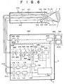
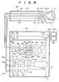
- Fig. 6 is a schematic drawing of the fourth embodiment of a fluorescent endoscope apparatus that is an application of a fluorescent-light image display apparatus implementing the fluorescent-light image display method according to the present invention. Note that in so far as it is not particularly required, further explanation of elements that are the same as those of the first embodiment shown in Fig. 1 has been omitted.
- the fluorescent endoscope comprises an endoscope insertion portion 150 for insertion into the body of a patient to a position near the location of the primary nidus and areas of suspected secondary infection, an image signal processing portion 5 for processing the data obtained of a target subject into an image signal, and a monitor 650 for displaying as a visible-image an image signal processed by the image signal processing portion 5.
- the image signal processing portion 5 comprises: an illuminating unit 160 provided with two light sources, one that emits white-light LW for obtaining standard-images, and one that emits excitation light Lr for obtaining autofluorescent-light images and reference-light Ls for obtaining reflected-light images; an image detection unit 350 for obtaining an autofluorescent-light image Zj formed of two different wavelength bands of fluorescent-light emitted from a target subject 9 upon the irradiation thereof by the excitation light Lr and a reflected-light image formed of the reflected-light reflected from the target subject 9 upon the irradiation thereof by the reference-light Ls, and converting the obtained images to digital values and outputting 2-dimensional image data thereof; an image computing unit 450 for performing a distance correction computation, and etc.
- a display signal processing unit 550 for digitizing the standard-image and obtaining a 2 -dimensional image data thereof and converting said 2-dimensional data and the output signal from the image computing unit 450 to video signals and outputting said video signals; a standard-image display controlling means 750 connected to an AD converter output irregularity detecting means 358 of the image detecting unit 350 and an AD converter output irregularity detecting means 554 of the display signal processing unit 550, for switching, in response to a detection signal from the AD converter output irregularity detecting means 358 and the AD converter output irregularity detecting means 554 indicating that an operational irregularity has occurred in either the autofluorescent-light image high-sensitivity imaging element 356 or the standard-image imaging element 107
- the AD converter output irregularity detecting means 358 and 554 occurring in the current embodiment detect an operational irregularity occurring in either the autofluorescent-light image high-sensitivity imaging element 356 or the standard-image imaging element 107 as an irregular output of the respective AD converter, and the detection signal thereof is output to the standard-image display controlling means 750.
- the insertion portion 150 comprises a light guide 101 extending internally to the forward end thereof, a CCD cable 152, and an image fiber 153.
- An illuminating lens 103 and an objective lens 106 are provided at the forward end of the CCD cable 152 and the light guide 101, that is, at the excitation lightdistal end of the endoscope insertion portion 150.
- the image fiber 153 is a fused quartz fiber, and a focusing lens 105 is provided at the forward end thereof.
- the standard-image imaging element 107 is connected to the forward end of the CCD cable 152, and a reflective prism 108 is attached to said standard-image imaging element 107.
- the illumination unit 160 comprises: a white-light source 114 that emits white-light Lw for obtaining standard-images and a white-light source drive apparatus 115 electrically connected to said white-light source 112; a white-light focusing lens 116 for focusing the white light emitted by said white light source 114; a GaN semiconductor laser 111 that emits excitation light Lr for obtaining autofluorescent-light images and a semiconductor-laser drive apparatus 112 electrically connected to said GaN semiconductor laser 111; and a excitation light focusing lens 113 for focusing the excitation light emitted from the GaN semiconductor laser.
- the white-light Lw emitted by the white-light emitting means contains light of a wavelength band that can be used as a reference-light Ls, the white-light source can be used as the reference-light source.
- the image detection unit 350 to which the image fiber 153 is connected, comprises: a fluorescent-light collimator lens 351 for conveying in focused form an autofluorescent-light image and a reflected-light image; a excitation light cutoff filter 352 for cutting off from the autofluorescent-light image wavelengths of light near the wavelength of the excitation light; an optical transmissive filter 353 for extracting the desired wavelengths of light from the autofluorescent-light image and the reflected-light image transmitted by the excitation light cutoff filter 352; a filter rotating means 354 for rotating the optical transmissive filter 353; a fluorescent-light focusing lens 355 for focusing the autofluorescent-light image and the reflected-light image transmitted by the optical transmissive filter 353; an autofluorescent-light image high-sensitivity imaging element 356 for obtaining the autofluorescent-light image and reflected-light image focused by the fluorescent-light focusing lens 355; an A/D converter 357 for digitizing and outputting as a 2-dimensional image data the auto
- the image computing unit 450 comprises: an image memory 451 for storing the digitized image signal data of an autofluorescent-light image and a reflected-light image; an autofluorescent-light image computing portion 452 for performing computations corresponding to the ratio between each pixel value of the autofluorescent-light image formed of two different wavelength bands of fluorescent-light and which has been stored in the image memory 451 and deriving a computed-value for each pixel, and assigning a color data to each of said computed values; a reflected-light image computing portion 453 for assigning a brightness data to each pixel value of a reflected-light image stored in the image memory 451; and an image composing portion 454 for combining the image signal having color data, which is output from the autofluorescent-light image computing portion 452 and the image signal having brightness data, which is output from the reflected-light image computing portion 453, and forming a composite-image.
- the image memory 451 is formed of a narrow-band autofluorescent-light image memory zone, a wide-band autofluorescent-light image memory zone, and a reflected-light image zone, which are not shown in the figure:
- the autofluorescent-light image transmitted by the optical transmissive filter 353a is stored in the wide-band autofluorescent-light image memory zone;
- the autofluorescent-light image transmitted by the optical transmissive filter 353b is stored in the narrow-band autofluorescent-light image memory zone;
- the autofluorescent-light image transmitted by the optical transmissive filter 353c is stored in the reflected-light image memory zone.
- the display signal processing unit 550 comprises: an A/D converter 551 for digitizing the visible-image signal obtained by the standard-image imaging element 107; a standard-image memory 552 for storing the digitized standard-image signal; and a video signal converting circuit 553 for converting the standard-image signal output from the standard-image memory 552 and the composite-image signal output from the image composing portion 454 to video signals; and an AD converter output irregularity detecting means 554 for detecting, by an irregular output of the AD converter 551, that an operational irregularity has occurred in the standard-image imaging element 107.
- the monitor unit 650 is provided with a standard-image monitor 651 and a composite-image monitor 652.
- the semiconductor -laser drive circuit 112 is activated based on a signal from the control computer 250, and the excitation light Lrhaving a wavelength of 410 nm is emitted from the GaN semiconductor laser 111.
- the excitation light Lr is transmitted by the excitation light focusing lens 113 and enters the excitation light guide 101b, and after being guided to the excitation lightdistal end of the endoscope insertion portion 150, said excitation light Lr is projected onto the target subject 9 by the illuminating lens 103.
- the autofluorescent-light image formed of the fluorescent-light emitted from the target subject 9 upon the irradiation thereof by the excitation light Lr is focused by the focusing lens 105 and enters the forward end of the image fiber 153, and after passing through the image fiber, said autofluorescent-light image enters the excitation light cutoff filter 352.
- the autofluorescent-light image transmitted by the excitation light cutoff filter 352 enters the optical transmissive filter 353.
- the excitation light cutoff filter is a long-pass filter that transmits all fluorescent-light having a wavelength of 420 nm and longer. Because the excitation light has a wavelength of 410 nm, the excitation light reflected from the target subject 9 is cutoff by the excitation light cutoff filter 352 and does not enter the optical transmissive filter 353.
- the control computer activates the filter rotating apparatus 354, and after the autofluorescent-image Zj has been transmitted by the optical transmissive filter 353a, it is focused by the fluorescent-light focusing lens 355 and obtained as a wide-band autofluorescent-light image by the wide-band autofluorescent-light image high-sensitivity imaging element 356; the visible-image signal output from the wide-band autofluorescent-light image high-sensitivity imaging element 356 is input to the A/D converter 357, and after being digitized, is stored in the image data memory 451.
- the wide-band autofluorescent-light image obtained by the wide-band autofluorescent-light image high-sensitivity imaging element 356 is stored in the wide-band autofluorescent-light image memory zone and the narrow-band autofluorescent-light image is stored in the narrow-band autofluorescent-light image memory zone of the image memory 451.
- the white-light source power source is activated based on a signal from the control computer 250, and the white-light Lw is emitted; this white-light Lw contains reference-light Ls having a wavelength within the 750 nm-900 nm wavelength band.
- the white-light Lw containing the reference-light Ls is transmitted by the white-light focusing lens 116 and enters the white-light guide 101a, and after being guided to the excitation lightdistal end of the endoscope insertion portion, it is projected onto the target subject 9 by the illuminating lens 103.
- the reflected-light image formed of the reflected-light reflected from the target subject 9 upon the irradiation thereof with the white-light Lw containing the reference-light Ls is transmitted by the focusing lens 105 and enters the forward end of the image fiber 153, and after passing through the image fiber 153, said reflected-light image enters the excitation light cutoff filter 352.
- the reflected-light image transmitted by the excitation light cutoff filter 352 enters the optical transmissive filter 353.
- the control computer activates the filter rotating apparatus 354, and after the reflected-light image has been transmitted by the band pass filter 353c, it is focused by the fluorescent-light focusing lens 355 and obtained by the wide-band autofluorescent-light image high-sensitivity imaging element 356; the image signal output from the wide-band autofluorescent-light image high-sensitivity imaging element 356 is input to the A/D converter 357, and after being digitized, is stored in the image data memory 451.
- the band-pass filter 353c transmits the reflected-light image formed of the reflected-light reflected from the target subject 9 upon the irradiation thereof by the reference-light Ls contained in the white-light Lw.
- the image signal output from the autofluorescent-light image computing portion 452 and the image signal output from the reflected-light image computing portion 453 are combined by the image composing portion 454.
- the composite-image formed thereof by the image composing portion 454 is DA converted by the video-signal processing circuit 553, and input to the monitor 650 and displayed on the composite-image monitor 652.
- the white-light source drive apparatus 115 is activated based on a signal from the control computer 250, and the white-light Lw is emitted from the white-light source 114.
- the white-light Lw enters the white-light guide 101a via the white-light focusing lens 116, and after being guided to the excitation lightdistal end of the endoscope insertion portion 150, said white-light Lw is projected onto the target subj ect by the illuminating lens 103.
- the reflected-light of the white-light Lw is focused by the objective lens 106, reflected by the reflective prism 108, and obtained by the standard-image imaging element 107.
- the image signal output from the standard-image imaging element 107 is input to the A/D converter 551, and after being digitized, is stored in the standard-image memory 552.
- the standard-image signal stored in the standard-image memory 552 is DA converted by the video-signal processing circuit 553, and input to the monitor 650 and displayed on the standard-image monitor 651 as a visible-image.
- the series of operations occurring when a standard-image is to be displayed and when a composite-image is to be displayed described above are controlled by the control computer 250. Note that the obtaining of an autofluorescent-light image, a reflected-light image, and a standard-image are performed alternately in a time-division manner.
- the irregularity thereof is detected by the AD converter output irregularity detecting means 358 or the AD conventer output irregularity detecting means 554, and the detection signal thereof is output to the standard-image display controlling means 750.
- the standard-image controlling means turns the semiconductor-laser drive apparatus 112 of the illumination unit 160 OFF to prevent the emission of the excitation light Lr and turns ON the white-light source 115 to cause the white-light to be emitted from the white-light source 114.
- the imaging element for which an operational irregularity has been detected to have occurred is the autofluorescent-light image high-sensitivity imaging element 356, the standard-image formedof the reflected-light of the white-light is obtained by the standard-image imaging element 107 and a standard-image is displayed.
- the standard image imaging element 356 the standard-image formed of the reflected-light of the white-light is obtained by the wide-band autofluorescent-light image high-sensitivity imaging element 356 and a standard-image is displayed.
- an AD converter output irregularity detecting means 358 and an AD converter output irregularity detecting means 554 are provided for detecting that an operational irregularity has occurred in either the wide-band autofluorescent-light image high-sensitivity imaging element 356 or the standard-image imaging element 107, and in response to the detection signal thereof, the emission of the excitation light is prevented, the white-light is emitted, an imaging element that is not operating irregularly is switched to and a standard-image is displayed on the monitor 651; whereby, for cases in which an operational irregularity is detected to have occurred in an imaging element, an imaging element that is not operating irregularly can be switched to and it is possible to continuously display a standard-image.
- Fig. 8 is a schematic drawing of a fluorescent-light image display apparatus implementing the fluorescent-light image display method according to the present invention as implemented in a fluorescent endoscope. Note that elements that are the same as those of the fourth embodiment shown in Fig. 6 are likewise labeled, and in so far as it is not particularly required, further explanation thereof has been omitted.
- the fluorescent endoscope comprises an endoscope insertion portion 260 for insertion into the body of a patient to a position near the location of the primary nidus and areas of suspected secondary infection, an image signal processing portion 6 for processing the data obtained of a target subject into an image signal, and a monitor 650 for displaying as a visible-image an image signal processed by the image signal processing portion 6.
- the image signal processing portion 6 comprises: an illuminating unit 270 provided with three light sources, one that emits white-light LW for obtaining standard-images, one that emits excitation light Lr for obtaining autofluorescent-light images, and one that emits reference-light Ls for obtaining reflected-light images; an image detection unit 360 for obtaining an autofluorescent-light image Zj formed of two different wavelength bands of fluorescent-light emitted from a target subject 9 upon the irradiation thereof by the excitation light Lr, and a reflected-light image formed of the reflected-light reflected from the target subject 9 upon the irradiation thereof by the reference-light Ls, and converting the obtained images to digital values and outputting 2-dimensional image data thereof; an image computing unit 460 for performing a distance correction computation, and etc.
- a display signal processing unit 550 for digitizing the standard-image and obtaining a 2-dimensional image data thereof and converting said 2-dimensional data and the output signal from the image computing unit 460 to video signals and outputting said video signals; a standard-image display controlling means 760 connected to an AD converter output irregularity detecting means 368 and an AD converter output irregularity detecting means 369 of the image detecting unit 360 and an AD converter output irregularity detecting means 554 of the display signal processing unit 550, for switching, in response to a detection signal from the AD converter output irregularity detecting means 368, 369, or 554 indicating that an operational irregularity has occurred in either the fluorescent-light image high-sensitivity imaging element 363, the reflected-light
- the insertion portion 260 comprises a light guide 261 extending internally to the forward end thereof, a CCD cable 152, and an image fiber 153.
- An illuminating lens 103 and an objective lens 106 are provided at the forward end of the CCD cable 152 and the light guide 261, that is, at the excitation lightdistal end of the endoscope insertion portion 260.
- the image fiber 153 is a fused quartz fiber, and a focusing lens 105 is provided at the forward end thereof.
- the standard-image imaging element 107 is connected to the forward end of the CCD cable 152, and a reflective prism 108 is attached to said standard-image imaging element 107.
- the light guide 261 comprises a composite glass fiber white-light guide 261a, a fused quartz fiber excitation light guide 261b, and a composite glass fiber reference-light guide 261c bundled together in the form of an integrated cable, and the white-light guide 261a, the excitation light guide 261b, and the reference-light guide 261c are connected to the illumination unit 270.
- One end of the CCD cable 152 is connected to the display signal processing unit 550, and one end of the image fiber 153 is connected to the image detection unit 350.
- the illumination unit 270 comprises: a white-light source 114 that emits white-light Lw for obtaining standard-images and a white-light source drive apparatus 115 electrically connected to said white-light source 112; a white-light focusing lens 116; a GaN semiconductor laser 111 that emits excitation light Lr for obtaining autofluorescent-light images and a semiconductor-laser drive apparatus 112 electrically connected to said GaN semiconductor laser 111; and a excitation light focusing lens 113 for focusing the excitation light emitted from the GaN semiconductor laser; a reference-light source 211 that emits reference-light Ls for obtaining reflected-light images and a reference-light source drive apparatus 212 electrically connected to said reference-light light source 211, and a reference-light focusing lens 213 for focusing the reference-light emitted from the reference-light source 211.
- the image detection unit 360 to which the image fiber 153 is connected, comprises: a fluorescent-light collimator lens 351 for conveying in focused form an autofluorescent-light image and a reflected-light image transmitted thereto by said image fiber 153; a excitation light cutoff filter 352 for cutting off from the autofluorescent-light image wavelengths of light near the wavelength of the excitation light; a dichroic mirror 361 that transmits light having a wavelength of 750 nm and higher and reflects at a right angle light having a wavelength shorter than 750 nm; a fluorescent-light image high-sensitivity imaging element 363 provided with an mosaic filter 362 mounted thereon for obtaining the fluorescent-light image transmitted by the dichroic mirror 361; an A/D converter 364 for digitizing and outputting as a 2-dimensional image data the autofluorescent-light image obtained by the fluorescent-light image high-sensitivity imaging element 363; a reflected-image imaging element 366 for obtaining the reflected-light image reflected by the dichroic mirror 361;
- the image computing unit 460 comprises: an autofluorescent-light image memory 461 for storing the digitized image signal data of an autofluorescent-light image formed of two different wavelength bands of fluorescent-light; a reflected-light image memory 462 for storing the digitized image data of a reflected-light image; an autofluorescent-light image computing portion 463 for performing computations corresponding to the ratio between each pixel value of the autofluorescent-light image formed of two different wavelength bands of fluorescent-light and which has been stored in the image memory 461 and deriving a computed-value for each pixel, and assigning a color data to each of said computed values; a reflected-light image computing portion 464 for assigning a brightness data to each pixel value of a reflected-light image stored in the image memory 462; and an image composing portion 465 for combining the image signal having color data, which is output from the autofluorescent-light image computing portion 452 and the image signal having brightness data, which is output from the reflected-light image
- the image memory 461 is formed of a narrow-band autofluorescent-light image memory zone, a wide-band autofluorescent-light image memory zone, which are not shown.
- the fluorescent-light image obtained by the pixels corresponding to the narrow-band autofluorescent-light image optical filter 362a of the fluorescent-light image high-sensitivity imaging element 363 is stored in the narrow-band auto fluorescent-light image memory zone; and the fluorescent-light image obtained by the pixels corresponding to the wide-band autofluorescent-light image optical filter 362b of the fluorescent-light image high-sensitivity imaging element 363 is stored in the wide-band autofluorescent-light image memory zone.
- the display signal processing unit 550 comprises: an A/D converter 551 for digitizing the image signal obtained by the standard-image imaging element 107; a standard-image memory 552 for storing the digitized standard-image signal; and a video signal converting circuit 553 for converting the standard-image signal output from the standard-image memory 552 and the composite-image signal output from the image composingportion 465 to video signals; and an AD converter output irregularity detecting means 554 for detecting, by irregular output of the AD converter 551, that an operational irregularity has occurred in the standard-image imaging element 107.
- the monitor unit 650 is provided with a standard-image monitor 651 and a composite-image monitor 652.
- the semiconductor-laser drive circuit 112 is activated based on a signal from the control computer 280 and the excitation light Lr having a wavelength of 410 nm is emitted from the GaN semiconductor laser 111.
- the excitation light Lr is transmitted by the excitation light focusing lens 113 and enters the excitation light guide 261b, and after being guided to the excitation lightdistal end of the endoscope insertion portion 260, said excitation light Lr is projected onto the target subject 9 by the illuminating lens 103.
- the autofluorescent-light image formed of the fluorescent-light emitted from the target subject 9 upon the irradiation thereof by the excitation light Lr is focused by the focusing lens 105 and enters the forward end of the image fiber 153, and after passing through the image fiber, said autofluorescent-light image enters the excitation light cutoff filter 352.
- the autofluorescent-light image transmitted by the excitation light cutoff filter 352 enters the dichroic mirror 361.
- the excitation light cutoff filter is a long-pass filter that transmits all fluorescent-light having a wavelength of 420 nm and longer. Because the excitation light has a wavelength of 410 nm, the excitation light reflected from the target subject 9 is cutoff by the excitation light cutoff filter 352 and does not enter the dichroic mirror 361.
- the autofluorescent-light image Zj transmitted by the excitation light cutoff filter 352 is focused by the fluorescent-light focusing lens 355 and enters the mosaic filter 362 mounted on the fluorescent-light image high-sensitivity imaging element 363.
- the fluorescent-light transmitted by the narrow-band autofluorescent-light image optical filter 362a of the mosaic filter becomes a narrow-band autofluorescent-light image
- the fluorescent-light transmitted by the wide-band autofluorescent-light image optical filter 362a of the mosaic filter becomes a wide-band autofluorescent-light image
- the narrow-band autofluorescent-light image and the wide-band autofluorescent-light image fluorescent-light image are obtained by the high-sensitivity imaging element 363; the visible-image signal output by the fluorescent-light image high-sensitivity imaging element 363 is input to the A/D converter 357, and after being digitized, are stored in the autofluorescent-light image memory 461.
- the narrow-band autofluorescent-light image and the wide-band autofluorescent-light image fluorescent-light image stored in the autofluorescent-light image memory 461 are subj ected to computations by the autofluorescent-light image computing portion 463 for corresponding to the ratio between each pixel value of each image to derive computed-value for each pixel, and a color data is assigned to each computed-value obtained thereby to form an image signal having color data, which is then output.
- the reference-light drive apparatus 212 When a reflected-light image is to be obtained, the reference-light drive apparatus 212 is activated based on a signal from the control computer 280 and the reference-light Ls is emitted.
- the reference-light Ls is transmitted by the reference-light focusing lens 213 and enters the reference-light guide 261c, and after being guided to the excitation lightdistal end of the endoscope insertion portion 260, said reference-light Ls is projected onto the target subject 9 by the illuminating lens 103.
- the reflected-light image formed of the reflected-light reflected-from the target subject 9 upon the irradiation thereof with the reference-light Ls is focused by the focusing lens 105 and enters the forward end of the image fiber 153, and after passing through the image fiber 153, said reflected-light image enters the excitation light cutoff filter 352.
- the reflected-light image transmitted by the excitation light cutoff filter 352 enters the dichroic mirror 361. Because the dichroic mirror 361 reflects at a right angle light having a wavelength of 750 nm and longer, the reflected-light of the reference-light is reflected, focused by the reflected-light image focusing lens 365, and obtained by the reflected-light image imaging element 366.
- the white-light source drive apparatus 115 is activated based on a signal from the control computer 280 and white-light Lw is emitted from the white-light source 114.
- the white-light Lw emitted from the white-light source 114 enters the white-light guide 261a via the white-light focusing lens 116, and after being guided to the excitation lightdistal end of the endoscope insertion portion 260, said white-light Lw is projected onto the target subject 9 by the illuminating lens 103.
- the reflected-light of the white-light Lw is focused by the objective lens 106, reflected by the reflective prism 108, and obtained by the standard-image imaging element 107.
- the image signal output by the standard- image imaging element 107 is input to the A/D converter 551, and after being digitized, is stored in the standard-image memory 552.
- the standard-image signal stored by the standard-image memory 552 is DA converted by the video signal processing circuit 553, after which it is output to the monitor 650 and displayed on the standard-image monitor 651 as a visible-image.
- the excitation light and the reference-light, and the white-light are controlled so as to be emitted at respectively different timings: at an emission timing of a one frame interval every 1/60 sec , so as to mutually not interfere, and because the excitation light and the reference-light are of mutually different wavelengths, the taking of a measurement is not hindered due to the emission of the respective other light.
- the standard-image display controlling means 760 by way of the control computer 280, turns OFF the semiconductor-laser drive apparatus 112 and the reference-light source drive apparatus 118 of the illuminating unit 270, thus preventing the emission of the excitation light Lr and the reference-light Ls, and turns ON the white-light source drive apparatus 115, causing the white-light Lw to be emitted from the white-light source 114.
- the standard-image formed of the reflected-light of the white-light is obtained by the standard-image imaging element 107, and the standard-image displayed.
- the standard-image formed of the reflected-light of the white-light is obtained by the reflected-light image imaging element 366, and the standard-image displayed.
- the standard-image formed of the reflected-light of the white-light is obtained by the fluorescent-light image imaging element 363, and the standard-image displayed; for cases in which the fluorescent-light image imaging element 363 is also operating irregularly, the standard-image formed of the reflected-light of the white-light is obtained by the reflected-light image imaging element 366, and the standard-image displayed.
- the standard-image formed of the reflected-light of the white-light is obtained by the standard-image imaging element 107, and the standard-image displayed; for cases in which the standard image imaging element 107 is also operating irregularly, the standard-image formed of the reflected-light of the white-light is obtained by the fluorescent-light image imaging element 363, and the standard-image displayed.
- the fluorescent-light image imaging element and the reflected-light image imaging element are not housed within the image signal processing portion, and can be disposed at the excitation lightdistal end of the endoscope insertion portion.
- a drawing of such a configuration is shown in Fig. 11.
- the endoscope insertion portion 170 is provided with a fluorescent-light CCD cable 174 extending internally to the forward end thereof.
- the fluorescent-light image high-sensitivity imaging element 171 and the reflected-light image imaging element 172 are connected to the forward end of the fluorescent-light CCD cable 174; and a reflecting prism 173 which transmits a reflected image of a reference light and reflects at a right angle fluorescent light of the excitation light is mounted there between target excitation light.
- the fluorescent-light image focused by the focusing lens 105 is reflected by the reflective prism 173, and obtained by the fluorescent-light image high-sensitivity imaging element 171.
- the reflected-light image formed of the reflected-light reflected from the target subject 9 upon the irradiation thereof by the reference-light LS is transmitted by the reflective prism 173, and obtained by the reflected-light image imaging element 172.
- the obtained autofluorescent-light image and reflected-light image are output to the image processing portion through the fluorescent-light CCD cable 174. Note that when a fluorescent endoscope of such a configuration is implemented in the fourth embodiment, the fluorescent-light image high-sensitivity imaging element 171 must be provided with the mosaic filter 362 mounted thereon occurring in the fifth embodiment.
- the monitor from among the standard-image monitor 651 and the composite-image monitor 652 that has been displaying the image obtained by an imaging element that has been detected to be operating irregularly can be caused to not display an image, to display a freeze-frame image, or to display an error message indicating that an operational irregularity of an imaging element has occurred.
- the standard-image monitor 651 and the composite-image monitor 652 are provided for displaying separate images, a single monitor combining the functions for displaying both images can be used.
- the method of switching between the displaying of a standard-image and a composite-image can be performed automatically in a time series manner controlled by the control computer, or can be a method whereby the displaying of the images is switched at will by an operator through an appropriate switching means.
- the standard-image and the composite-image can be superposed and displayed.
- the image fiber 153 can be formed of a composite glass fiber instead of a fused quartz fiber.
- a excitation light cutoff filter 352 must be disposed between the focusing lens 105 and the autofluorescent-light image input face of the image fiber 153.
- an operational irregularity occurring in an imaging element has been detected by an output irregularity of the respective AD converter
- a configuration wherein both an operational irregularity occurring in the output of an AD converter and an irregularity in the drive-current of an imaging element drive circuit are detected can be adopted.
- the computational processing performed by the autofluorescent-light image computing portion, the reflected-light image computing portion, and the image composing portion is not limited to being performed for each pixel position: the computational processing can be performed for pixel units corresponding to binning processing carried out by the fluorescent-light image high-sensitivity imaging element; or a horizontal x vertical block (nxm) of pixels desired by an operator. Alternatively, computational processing can be performed only on a pixel area specified by an operator, or, a selection of pixel areas determined based on consideration of the volume of computation required for processing.
- any excitation light source producing excitation light having a wavelength in the 400 nm-420 nm wavelength range can be adopted.
- the excitation light source and the white-light source have been provided as separate light sources, by use of an appropriate optical filter, the light source can be made into a combined light source.
- the fluorescent-light image display apparatus can also be implemented in an apparatus for detecting the fluorescent-light emitted from a target subject, which has absorbed a fluorescent diagnostic chemical, upon the irradiation thereof by a excitation light.
Landscapes
- Health & Medical Sciences (AREA)
- Life Sciences & Earth Sciences (AREA)
- Surgery (AREA)
- Engineering & Computer Science (AREA)
- General Health & Medical Sciences (AREA)
- Molecular Biology (AREA)
- Pathology (AREA)
- Veterinary Medicine (AREA)
- Public Health (AREA)
- Biophysics (AREA)
- Biomedical Technology (AREA)
- Heart & Thoracic Surgery (AREA)
- Medical Informatics (AREA)
- Physics & Mathematics (AREA)
- Animal Behavior & Ethology (AREA)
- Optics & Photonics (AREA)
- Nuclear Medicine, Radiotherapy & Molecular Imaging (AREA)
- Radiology & Medical Imaging (AREA)
- Signal Processing (AREA)
- Endoscopes (AREA)
- Investigating, Analyzing Materials By Fluorescence Or Luminescence (AREA)
Applications Claiming Priority (3)
| Application Number | Priority Date | Filing Date | Title |
|---|---|---|---|
| JP2000234225A JP4321697B2 (ja) | 2000-08-02 | 2000-08-02 | 蛍光画像表示方法および装置 |
| JP2000234225 | 2000-08-02 | ||
| EP01118539A EP1177761B1 (fr) | 2000-08-02 | 2001-08-01 | Procédé d'imagerie de la lumière fluorescente et appareil de mise en oeuvre |
Related Parent Applications (1)
| Application Number | Title | Priority Date | Filing Date |
|---|---|---|---|
| EP01118539A Division EP1177761B1 (fr) | 2000-08-02 | 2001-08-01 | Procédé d'imagerie de la lumière fluorescente et appareil de mise en oeuvre |
Publications (1)
| Publication Number | Publication Date |
|---|---|
| EP1609409A1 true EP1609409A1 (fr) | 2005-12-28 |
Family
ID=18726625
Family Applications (4)
| Application Number | Title | Priority Date | Filing Date |
|---|---|---|---|
| EP01118539A Expired - Lifetime EP1177761B1 (fr) | 2000-08-02 | 2001-08-01 | Procédé d'imagerie de la lumière fluorescente et appareil de mise en oeuvre |
| EP05015242A Withdrawn EP1609408A1 (fr) | 2000-08-02 | 2001-08-01 | Procédé d'imagerie de la lumière fluorescente et appareil de mise en oeuvre |
| EP05015241A Withdrawn EP1609407A1 (fr) | 2000-08-02 | 2001-08-01 | Procédé d'imagerie de la lumière fluorescente et appareil de mise en oeuvre |
| EP05015243A Withdrawn EP1609409A1 (fr) | 2000-08-02 | 2001-08-01 | Procédé d'imagerie de la lumière fluorescente et appareil de mise en oeuvre |
Family Applications Before (3)
| Application Number | Title | Priority Date | Filing Date |
|---|---|---|---|
| EP01118539A Expired - Lifetime EP1177761B1 (fr) | 2000-08-02 | 2001-08-01 | Procédé d'imagerie de la lumière fluorescente et appareil de mise en oeuvre |
| EP05015242A Withdrawn EP1609408A1 (fr) | 2000-08-02 | 2001-08-01 | Procédé d'imagerie de la lumière fluorescente et appareil de mise en oeuvre |
| EP05015241A Withdrawn EP1609407A1 (fr) | 2000-08-02 | 2001-08-01 | Procédé d'imagerie de la lumière fluorescente et appareil de mise en oeuvre |
Country Status (4)
| Country | Link |
|---|---|
| US (1) | US6747281B2 (fr) |
| EP (4) | EP1177761B1 (fr) |
| JP (1) | JP4321697B2 (fr) |
| DE (1) | DE60123884T2 (fr) |
Cited By (3)
| Publication number | Priority date | Publication date | Assignee | Title |
|---|---|---|---|---|
| CN110799081A (zh) * | 2017-07-18 | 2020-02-14 | 富士胶片株式会社 | 内窥镜装置及测量支持方法 |
| US11363939B2 (en) | 2018-06-19 | 2022-06-21 | Olympus Corporation | Endoscope system, operation method of endoscope system and recording medium |
| US11986147B2 (en) | 2018-06-19 | 2024-05-21 | Olympus Corporation | Endoscope system, method for operating endoscope system and storage medium |
Families Citing this family (51)
| Publication number | Priority date | Publication date | Assignee | Title |
|---|---|---|---|---|
| JP2001070227A (ja) * | 1999-07-07 | 2001-03-21 | Fuji Photo Film Co Ltd | 蛍光観察装置 |
| US7794394B2 (en) * | 2002-05-22 | 2010-09-14 | Beth Israel Deaconess Medical Center | Device for wavelength-selective imaging |
| JP2004305373A (ja) * | 2003-04-04 | 2004-11-04 | Pentax Corp | 電子内視鏡システム |
| JP2005204910A (ja) * | 2004-01-22 | 2005-08-04 | Pentax Corp | 内視鏡装置 |
| JP4495511B2 (ja) * | 2004-05-06 | 2010-07-07 | Hoya株式会社 | 内視鏡システム |
| JP4786910B2 (ja) * | 2005-02-07 | 2011-10-05 | Hoya株式会社 | 電子内視鏡 |
| JP5173120B2 (ja) * | 2005-05-23 | 2013-03-27 | オリンパスメディカルシステムズ株式会社 | 内視鏡装置 |
| US8764636B2 (en) | 2005-06-21 | 2014-07-01 | Olympus Medical Systems Corp. | Electronic endoscopic apparatus |
| JP5063872B2 (ja) * | 2005-07-04 | 2012-10-31 | オリンパスメディカルシステムズ株式会社 | 電子内視鏡装置 |
| JP2007000373A (ja) * | 2005-06-23 | 2007-01-11 | Olympus Medical Systems Corp | 電子内視鏡 |
| JP5191090B2 (ja) * | 2005-07-15 | 2013-04-24 | オリンパスメディカルシステムズ株式会社 | 内視鏡装置 |
| US8451327B2 (en) | 2005-08-18 | 2013-05-28 | Hoya Corporation | Electronic endoscope, endoscope light unit, endoscope processor, and electronic endoscope system |
| JP4681981B2 (ja) * | 2005-08-18 | 2011-05-11 | Hoya株式会社 | 電子内視鏡装置 |
| JP4694311B2 (ja) * | 2005-08-22 | 2011-06-08 | Hoya株式会社 | 内視鏡プロセッサ、画像切替えプログラム、および蛍光内視鏡システム |
| JP4827491B2 (ja) | 2005-10-26 | 2011-11-30 | Hoya株式会社 | 内視鏡用光源装置 |
| WO2008065955A1 (fr) * | 2006-11-28 | 2008-06-05 | Olympus Corporation | Dispositif d'endoscope |
| US8310604B2 (en) * | 2007-10-26 | 2012-11-13 | GE Sensing & Inspection Technologies, LP | Visual inspection apparatus having light source bank |
| US20090289200A1 (en) * | 2008-05-22 | 2009-11-26 | Fujifilm Corporation | Fluorescent image obtainment method and apparatus, fluorescence endoscope, and excitation-light unit |
| DE102008034008B4 (de) | 2008-07-21 | 2010-07-01 | Carl Zeiss Surgical Gmbh | Filtersatz zur Beobachtung von Fluoreszenzstrahlung in biologischem Gewebe |
| JP5127639B2 (ja) * | 2008-09-10 | 2013-01-23 | 富士フイルム株式会社 | 内視鏡システム、およびその作動方法 |
| EP2365773B1 (fr) | 2008-11-18 | 2019-06-12 | Stryker Corporation | Source de lumière de type diode électroluminescente endoscopique possédant un système de commande rétroactif |
| JP5271062B2 (ja) * | 2008-12-09 | 2013-08-21 | 富士フイルム株式会社 | 内視鏡装置およびその作動方法 |
| JP5337676B2 (ja) * | 2009-06-25 | 2013-11-06 | 株式会社日立ハイテクノロジーズ | 蛍光分析装置および蛍光検出装置 |
| GB201011913D0 (en) * | 2010-07-15 | 2010-09-01 | Lux Innovate Ltd | Detecting device |
| JP5371921B2 (ja) * | 2010-09-29 | 2013-12-18 | 富士フイルム株式会社 | 内視鏡装置 |
| JP5371920B2 (ja) * | 2010-09-29 | 2013-12-18 | 富士フイルム株式会社 | 内視鏡装置 |
| DE102011005432A1 (de) | 2011-03-11 | 2012-09-13 | Hellma Gmbh & Co. Kg | Vorrichtung für die Analyse einer kleinen Flüssigkeitsmenge |
| US9795285B2 (en) * | 2011-07-07 | 2017-10-24 | Boston Scientific Scimed, Inc. | Imaging system for endoscope |
| KR101238765B1 (ko) * | 2011-09-22 | 2013-03-04 | 주식회사 옵티메드 | 일회용 내시경 |
| JP5467181B1 (ja) | 2012-03-29 | 2014-04-09 | オリンパスメディカルシステムズ株式会社 | 内視鏡システム |
| JP5623469B2 (ja) | 2012-07-06 | 2014-11-12 | 富士フイルム株式会社 | 内視鏡システム、内視鏡システムのプロセッサ装置、及び内視鏡用制御プログラム |
| WO2014038352A1 (fr) * | 2012-09-07 | 2014-03-13 | オリンパスメディカルシステムズ株式会社 | Dispositif de source de lumière et système d'endoscope |
| JP6157135B2 (ja) * | 2013-02-07 | 2017-07-05 | オリンパス株式会社 | 光源撮像装置 |
| EP2967299B1 (fr) | 2013-03-15 | 2022-11-30 | Stryker Corporation | Source de lumière endoscopique et système d'imagerie |
| JP5654167B1 (ja) * | 2013-07-03 | 2015-01-14 | 富士フイルム株式会社 | 内視鏡システム及びその作動方法 |
| WO2015029595A1 (fr) | 2013-08-27 | 2015-03-05 | 株式会社日立ハイテクノロジーズ | Dispositif d'analyse d'acide nucléique et procédé de diagnostic de dispositif |
| GB201317968D0 (en) * | 2013-10-10 | 2013-11-27 | Univ Glasgow | Endoscopy capsule |
| DE102013111368A1 (de) * | 2013-10-15 | 2015-04-16 | Karl Storz Gmbh & Co. Kg | Endoskopische, exoskopische oder mikroskopische Vorrichtung zur Fluoreszenzdiagnose |
| EP3050492A4 (fr) * | 2013-10-30 | 2017-09-20 | Olympus Corporation | Unité de source lumineuse et dispositif d'endoscope |
| US20170181636A1 (en) * | 2014-05-23 | 2017-06-29 | Covidien Lp | Systems for imaging of blood flow in laparoscopy |
| CN105899124B (zh) * | 2014-09-03 | 2018-07-10 | 奥林巴斯株式会社 | 内窥镜装置 |
| JP6110887B2 (ja) * | 2015-03-17 | 2017-04-05 | 浜松ホトニクス株式会社 | 重畳画像生成装置及び重畳画像生成装置の作動方法 |
| US10690904B2 (en) | 2016-04-12 | 2020-06-23 | Stryker Corporation | Multiple imaging modality light source |
| CN105796044B (zh) * | 2016-05-25 | 2017-08-25 | 珠海康弘发展有限公司 | 内窥镜及其成像方法 |
| KR102526757B1 (ko) * | 2017-08-30 | 2023-04-27 | 삼성전자주식회사 | 분광기용 집광 광학계 및 이를 포함하는 라만 분광 시스템 |
| DE102017129837A1 (de) * | 2017-12-13 | 2019-06-13 | Leibniz-Institut für Photonische Technologien e. V. | Kombinierte Untersuchung mit Bildgebung und Lasermessung |
| JP2019185002A (ja) * | 2018-04-11 | 2019-10-24 | ソニー株式会社 | 顕微鏡システム及び医療用光源装置 |
| JP7091211B2 (ja) * | 2018-09-28 | 2022-06-27 | オリンパス株式会社 | 内視鏡装置、処理状態切替方法、ネットワーク装置、及び医療システム |
| EP3931550A4 (fr) * | 2019-02-26 | 2022-11-23 | Al Biomed Corp. | Système de détection tissulaire et ses procédés d'utilisation |
| JP2020202955A (ja) * | 2019-06-17 | 2020-12-24 | 株式会社島津製作所 | イメージング装置 |
| DE102021001955B4 (de) | 2021-04-14 | 2023-03-23 | Baumer Inspection Gmbh | Vorrichtung und Verfahren zur fluoreszenzbasierten Inspektion sowie Prüfanordung mit einer solchen Vorrichtung |
Citations (4)
| Publication number | Priority date | Publication date | Assignee | Title |
|---|---|---|---|---|
| US4704520A (en) * | 1984-05-02 | 1987-11-03 | Olympus Optical Co., Ltd. | Light source device for an endoscope |
| US5115126A (en) * | 1989-09-06 | 1992-05-19 | Richard Wolf Gmbh | Means for checking endoscope equipment |
| WO1999053832A1 (fr) * | 1998-04-20 | 1999-10-28 | Xillix Technologies Corp. | Systeme d'imagerie avec commande de gain automatique pour endoscopie par reflectance et fluorescence |
| WO2000042910A1 (fr) * | 1999-01-26 | 2000-07-27 | Newton Laboratories, Inc. | Systeme d'imagerie a autofluorescence pour endoscopie |
Family Cites Families (6)
| Publication number | Priority date | Publication date | Assignee | Title |
|---|---|---|---|---|
| US4590924A (en) * | 1983-09-21 | 1986-05-27 | Olympus Optical Co., Ltd. | Endoscope system |
| US5334841A (en) * | 1993-01-22 | 1994-08-02 | Minnesota Mining And Manufacturing Company | Method and apparatus for detecting fluorescence |
| DE4331232C2 (de) * | 1993-09-15 | 1997-06-12 | Hans Werner Steudel | Einrichtung zur Kontrolle des Transmissionsgrades bei optischen Geräten mit Lichtleitmedien, insbesondere bei medizinischen Endoskopieeinrichtungen |
| JP3796635B2 (ja) * | 1996-03-06 | 2006-07-12 | 富士写真フイルム株式会社 | 蛍光検出装置 |
| WO1998008430A1 (fr) * | 1996-08-26 | 1998-03-05 | Stryker Corporation | Endoscope avec source lumineuse integree autoregulatrice |
| JPH11104060A (ja) * | 1997-10-03 | 1999-04-20 | Olympus Optical Co Ltd | 蛍光観察装置 |
-
2000
- 2000-08-02 JP JP2000234225A patent/JP4321697B2/ja not_active Expired - Fee Related
-
2001
- 2001-08-01 DE DE60123884T patent/DE60123884T2/de not_active Expired - Lifetime
- 2001-08-01 EP EP01118539A patent/EP1177761B1/fr not_active Expired - Lifetime
- 2001-08-01 EP EP05015242A patent/EP1609408A1/fr not_active Withdrawn
- 2001-08-01 EP EP05015241A patent/EP1609407A1/fr not_active Withdrawn
- 2001-08-01 EP EP05015243A patent/EP1609409A1/fr not_active Withdrawn
- 2001-08-02 US US09/919,853 patent/US6747281B2/en not_active Expired - Fee Related
Patent Citations (4)
| Publication number | Priority date | Publication date | Assignee | Title |
|---|---|---|---|---|
| US4704520A (en) * | 1984-05-02 | 1987-11-03 | Olympus Optical Co., Ltd. | Light source device for an endoscope |
| US5115126A (en) * | 1989-09-06 | 1992-05-19 | Richard Wolf Gmbh | Means for checking endoscope equipment |
| WO1999053832A1 (fr) * | 1998-04-20 | 1999-10-28 | Xillix Technologies Corp. | Systeme d'imagerie avec commande de gain automatique pour endoscopie par reflectance et fluorescence |
| WO2000042910A1 (fr) * | 1999-01-26 | 2000-07-27 | Newton Laboratories, Inc. | Systeme d'imagerie a autofluorescence pour endoscopie |
Cited By (3)
| Publication number | Priority date | Publication date | Assignee | Title |
|---|---|---|---|---|
| CN110799081A (zh) * | 2017-07-18 | 2020-02-14 | 富士胶片株式会社 | 内窥镜装置及测量支持方法 |
| US11363939B2 (en) | 2018-06-19 | 2022-06-21 | Olympus Corporation | Endoscope system, operation method of endoscope system and recording medium |
| US11986147B2 (en) | 2018-06-19 | 2024-05-21 | Olympus Corporation | Endoscope system, method for operating endoscope system and storage medium |
Also Published As
| Publication number | Publication date |
|---|---|
| DE60123884T2 (de) | 2007-05-31 |
| EP1177761A2 (fr) | 2002-02-06 |
| EP1177761A3 (fr) | 2003-10-22 |
| US20020014595A1 (en) | 2002-02-07 |
| EP1609408A1 (fr) | 2005-12-28 |
| EP1609407A1 (fr) | 2005-12-28 |
| JP4321697B2 (ja) | 2009-08-26 |
| EP1177761B1 (fr) | 2006-10-18 |
| JP2002045330A (ja) | 2002-02-12 |
| US6747281B2 (en) | 2004-06-08 |
| DE60123884D1 (de) | 2006-11-30 |
Similar Documents
| Publication | Publication Date | Title |
|---|---|---|
| US6747281B2 (en) | Flourescent—light image display method and apparatus therefor | |
| US11770503B2 (en) | Imaging systems and methods for displaying fluorescence and visible images | |
| US6687534B2 (en) | Fluorescent-light image display apparatus | |
| JP5245832B2 (ja) | 顕微鏡システム | |
| JP5451956B2 (ja) | コンパクトな蛍光内視鏡映像システム | |
| JP4444657B2 (ja) | カメラ内に移動部品を有さない蛍光内視鏡ビデオシステム | |
| US20060052710A1 (en) | Endoscope apparatus and fluorescence detection method using endoscope apparatus | |
| JPWO2018180631A1 (ja) | 医療用画像処理装置及び内視鏡システム並びに医療用画像処理装置の作動方法 | |
| JP2007506487A (ja) | 拡張ダイナミックレンジ撮像内視鏡システムに関する装置と方法 | |
| WO2008089545A1 (fr) | Système d'imagerie de fluorescence et de réflectance à longueurs d'onde multiples | |
| JP2007311114A (ja) | 白色光を発する固体発光素子を用いた照明光学系、及びそれを備えた光学装置 | |
| JP2012508034A (ja) | 内蔵偏光led照明を有する高解像度デジタルビデオコルポスコープおよびコンピュータ化された臨床データ管理システム | |
| JPH10328129A (ja) | 蛍光観察装置 | |
| JP6827516B2 (ja) | 内視鏡システム及び内視鏡システムの駆動方法 | |
| JP2004024656A (ja) | 蛍光内視鏡装置 | |
| US6640131B1 (en) | Device for photodynamic diagnosis or treatment | |
| JP4855755B2 (ja) | 生体診断装置 | |
| US20030216626A1 (en) | Fluorescence judging method and apparatus | |
| JP2004243119A (ja) | 組織の画像診断用装置 | |
| JP2002291682A (ja) | 蛍光観察用内視鏡装置 | |
| JP2002345739A (ja) | 画像表示装置 | |
| US20230218145A1 (en) | Endoscopic system and method for displaying an adaptive overlay | |
| JP2021186321A (ja) | 内視鏡システム | |
| JP2006158735A (ja) | 内視鏡、及び内視鏡撮像システム |
Legal Events
| Date | Code | Title | Description |
|---|---|---|---|
| PUAI | Public reference made under article 153(3) epc to a published international application that has entered the european phase |
Free format text: ORIGINAL CODE: 0009012 |
|
| 17P | Request for examination filed |
Effective date: 20050713 |
|
| AC | Divisional application: reference to earlier application |
Ref document number: 1177761 Country of ref document: EP Kind code of ref document: P |
|
| AK | Designated contracting states |
Kind code of ref document: A1 Designated state(s): DE FR GB |
|
| AKX | Designation fees paid |
Designated state(s): DE FR GB |
|
| RAP1 | Party data changed (applicant data changed or rights of an application transferred) |
Owner name: FUJIFILM CORPORATION |
|
| STAA | Information on the status of an ep patent application or granted ep patent |
Free format text: STATUS: THE APPLICATION IS DEEMED TO BE WITHDRAWN |
|
| 18D | Application deemed to be withdrawn |
Effective date: 20100302 |