US4590924A - Endoscope system - Google Patents
Endoscope system Download PDFInfo
- Publication number
- US4590924A US4590924A US06/649,527 US64952784A US4590924A US 4590924 A US4590924 A US 4590924A US 64952784 A US64952784 A US 64952784A US 4590924 A US4590924 A US 4590924A
- Authority
- US
- United States
- Prior art keywords
- data
- error
- communication
- endoscope
- units
- Prior art date
- Legal status (The legal status is an assumption and is not a legal conclusion. Google has not performed a legal analysis and makes no representation as to the accuracy of the status listed.)
- Expired - Lifetime
Links
Images


Classifications
-
- H—ELECTRICITY
- H04—ELECTRIC COMMUNICATION TECHNIQUE
- H04L—TRANSMISSION OF DIGITAL INFORMATION, e.g. TELEGRAPHIC COMMUNICATION
- H04L1/00—Arrangements for detecting or preventing errors in the information received
- H04L1/004—Arrangements for detecting or preventing errors in the information received by using forward error control
-
- A—HUMAN NECESSITIES
- A61—MEDICAL OR VETERINARY SCIENCE; HYGIENE
- A61B—DIAGNOSIS; SURGERY; IDENTIFICATION
- A61B1/00—Instruments for performing medical examinations of the interior of cavities or tubes of the body by visual or photographical inspection, e.g. endoscopes; Illuminating arrangements therefor
- A61B1/04—Instruments for performing medical examinations of the interior of cavities or tubes of the body by visual or photographical inspection, e.g. endoscopes; Illuminating arrangements therefor combined with photographic or television appliances
- A61B1/042—Instruments for performing medical examinations of the interior of cavities or tubes of the body by visual or photographical inspection, e.g. endoscopes; Illuminating arrangements therefor combined with photographic or television appliances characterised by a proximal camera, e.g. a CCD camera
Definitions
- the present invention relates to an endoscope system and, more paticularly, to an endoscope system having a data communication function.
- An endoscope system includes at least an endoscope, an endoscope camera and a light source device.
- an endoscope, an endoscope camera, and a light source device can have data processing and data communication functions.
- data communication when data is transmitted from a transmission station to a reception station, the reception station generates a response signal when it receives the data. Then, when the transmission station receives this response signal, it can transmit next data.
- the transmission station is set in a data transmission waiting state. On the other hand, the reception station is set in a reception waiting state until it receives all the data to be received.
- an endoscope system comprising an error detecting unit which is provided in an endoscope light source device and detects an error of communication data, an error counter for counting the number of errors which are detected by the error detecting unit, and an error recovering unit for performing an error recovery operation immediately after an error is detected when the number of the errors counted by the error counter is below a predetermined value, and for performing the error recovery operation after a predetermined time period when the number of errors exceeds the predetermined value.
- an endoscope system comprising, for data communication between an endoscope camera and a light source device, a data transmission unit for transmitting data; and a data reception unit for generating a data reception signal when it receives the data from the data transmission unit; the data transmission unit including a data adding unit for adding predetermined data to normal data in order to release a waiting state of the data reception unit due to a data transmission error.
- an endoscope system comprising an error detecting unit which is provided at least in one of two communication circuit units provided for an endoscope, an endoscope camera and a light source device and detects a data communication error; and a circuit unit for resetting the other communication circuit unit in response to an error detection by the error detecting unit.
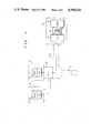
- FIG. 1 is a block diagram of an endoscope system according to an embodiment of the present invention
- FIG. 2 is a representation showing a data format
- FIG. 3 is a flow chart showing a sequence of the error detection and error recovery operations
- FIG. 4 is a circuit diagram of a circuit for resetting a communication interface unit
- FIG. 5 is a timing chart showing an operation timing of the circuit of FIG. 4.
- FIG. 6 is a circuit diagram of an error detection/recovery circuit.
- FIG. 1 shows a block circuit of a communication system of an endoscope system.
- a still camera 13 is mounted on an eyepiece of an endoscope 11 through an adaptor 12.
- a video camera 14 can be mounted on the adaptor 12.
- a universal cord 11a of the endoscope 11 is coupled to a light source device 15.
- a host computer (HOST) 16 and a communication interface unit (CIU) 17 are respectively provided in the light source device 15.
- the HOST 16 and the CIU 17 are coupled to each other by a data bus 18 and signal lines IS3, OS3 and STATUS.
- the cameras 13 and 14 respectively comprise circuits 19 and 20 in each of which a HOST and a CIU are mounted in one chip.
- the light source device 15 becomes a master station, and the cameras 13 and 14 become slave stations.
- data has a format shown in FIG. 2.
- the data comprising a destination address, a self address, a data length N and text data have N+3 bytes, and sum check data SMD is added after this data string.
- the sum check data SMD is a two's complement of a sum (1 byte) obtained by adding N+3 bytes (i.e., from first to last bytes of this data string) by neglecting a carry, that is, data of (N+4)th byte.
- the sum check operation is also performed.
- the CIU 17 detects a sum check error
- the error detection and recovery modes are executed in accordance with sequences 1 to 4 in the order named, as shown in the flow chart of FIG. 3.
- the HOST 16 detects a sum check error
- the error detection and recovery modes are executed in accordance with the order of sequences 1 ⁇ 3 ⁇ 4.
- the transmission side for example, the HOST 16 adds N+3 bytes (from first to last bytes of the transmission data), i.e., all bytes of the destination address, the self address, the data length N and the text data in the format of FIG. 2. Then, the two's complement of the sum is added after the text data as the sum check data SMD.
- the reception side adds all the data string (N+4 bytes) including the data SMD. When the sum becomes 0, it is determined that no error has occurred. When this sum does not become 0, it is determined that an error has occurred.
- the CIU 17 transmits a retransmission request code to the HOST 16. In this case, the CIU 17 transmits the retransmission request code in the following format.
- the CIU 17 can be reset in a hardware manner, as shown in FIG. 4.
- an output from a reset circuit 21 with respect to the overall system is coupled to reset terminals R and R of a central processing unit (CPU) 22 and a parallel port interface (PPI) 23, respectively.
- the CPU 22 and the PPI 23 are coupled with each other by a data bus 24, and an output RES from the PPI 23 is coupled to a reset terminal R of the CIU 17.
- the CPU 22 when the CPU 22 is reset by the reset circuit 21, the CPU 22 resets the CIU 17 through the data bus 24 and the PPI 23 during execution of a program.
- the CIU 17 is reset by the CPU 22 independent of a reset timing of the reset circuit 21.
- the CIU 17 is reset in accordance with execution of the program of the CPU 22.
- FIG. 5 shows a timing chart of a reset timing. According to this timing chart, when a power supply is high, the CPU 22 and the PPI 23 are respectively reset and are set at an initial setting interval t of the CPU 22. Note that a and b in the input RES to the CIU 17 represent a state wherein the CIU 17 is arbitrarily reset by the CPU 22.
- the CIU 17 When data is to be transmitted from the CIU 17 to the HOST 16, the CIU 17 sets the line STATUS at low level. In this case, the CIU 17 transmits to the signal line OS3 a pulse which represents that the data is transmitted. This pulse to the line OS3 serves as an interrupt signal.
- the HOST 16 receives the pulse of the line OS3, it fetches the data from the CIU 17 and transmits a signal representing data reception to the line IS3.
- the data In the data transmission from the HOST 16 to the CIU 17, the data is transmitted after the HOST 16 recognized that the CIU 17 sets the STATUS at high level.
- a pulse is transmitted to the line IS3 so as to inform the CIU 17 that data is transmitted.
- the CIU 17 transmits to the HOST 16 through the line OS3 a pulse representing that it has received the data. Such data transmission/reception are performed alternately.
- the transmission side is set in the state wherein it wants to transmit the data SMD, but cannot transmit, that is, into the waiting state.
- the CIU 17 is reset by the sum check error detection, thereby recovering the error data.
- the reception side is still awaiting data though the transmission side has transmitted all the data. In such a reception waiting state, if additional data is transmitted, the reception of data is completed, thereby releasing the reception waiting state. In this case, the reception data is checked by the sum check operation. Polling address range designation data is used as this additional data having no influence no other data.
- the polling address range designation data means data falling within the range of addresses 2 to 5. In addition, this data has no influence on the data to be generated and transmitted/received in the polling operation.
- the line STATUS is kept at high level.
- the CIU 17 receives the data, it sequentially polls the slave stations. Then, when the CIU 17 receives a response signal from the slave station, e.g., the camera 14, it sets a new mode, thereby transmitting data to the responded camera 14. During this interval, the line STATUS is kept at low level, and communication from the HOST 16 to the CIU 17 cannot be performed. During this interval, when the CIU 17 polls the slave station, for example, a CIU of the camera 14, if the data is wrong, this polling operation is repeated. In this case, the line STATUS is maintained at low level.
- the interval in which the line STATUS is maintained at low level is 100 msec in the correct operation mode. Therefore, when the low level interval of the line STATUS is too long, for example, 500 msec, the HOST 16 determines that an abnormality has occurred between the CIU 17 and the CIU of the slave station. Then, the HOST 16 resets the CIU 17, thus avoiding a dead-lock state.
- the HOST 16 transmits the data to the CIU 17, the CIU 17 generates a response signal representing that the data has been received. However, in this case, when the response signal is erased by noise, the HOST 16 does not receive this signal. In this case, when the HOST 16 does not receive the response signal within 20 msec of transmitting the data, the HOST 16 determines that an abnormality has occurred in the CIU 17, and resets it.
- the HOST 16 when an abnormality occurs, that is, when the reception data is error data, when the line STATUS is kept at low level for 500 msec or more, or when no response signal is transmitted within 20 msec of data transmission, the HOST 16 resets the CIU 17. After resetting, polling range designation is performed. Then, if no response signal is transmitted with respect to this polling range designation, the HOST 16 resets the CIU 17 again. In this manner, the reset operation is repeated until a response signal is transmitted. When the reset operation is repeated in this manner, it is performed for a short time period, for e.g., the first four times, and thereafter it is performed at an interval of 1 sec. In this manner, an error due to noise generated by sudden thunder, etc., can be recovered at high speed. On the other hand, continuous noise due to the operation of an electric knife or the like can be recovered without influence to an execution speed of other processing.
- FIG. 6 shows hardware of the error detection/recovery circuit.
- the data is received by a reception buffer 25.
- the data from the reception buffer 25 is transferred to a discriminator buffer 26.
- An error detection circuit 27 discriminates whether or not the data has an error.
- the error detection circuit 27 is coupled to a monitor 28 (e.g., a timer) of the lines STATUS and OS3.
- the circuit 27 discriminates whether or not the data has an error by checking a sum of the reception data, an over time, and re-request thereof.
- pulses IS3 and OS3 here mean "data is transmitted” and “data is received”, respectively, and they are exchanged in accordance with a communication direction.
- the reception station when the data is transmitted from a data output circuit 36 through a transmission buffer 35, a part of the transmission data is erased due to noise and the reception station is set in a reception waiting state. In this state, when next data is transmitted and polling range designation data generated from a polling range designating circuit 37 is received by the CIU 17 before receiving the normal data, the CIU 17 is released from the reception waiting state by this data and performs the sum check operation including this data.
- the error detection circuit 27 When the error detection circuit 27 detects an error, it supplies a detection signal to a counter 38 and an AND gate 29.
- the counter 38 counts the number of errors from the detection signal.
- the counter 38 generates the count signal corresponding to four errors or less to the AND gate 29.
- the AND gate 29 supplies an error signal of four errors or less to a CIU reset circuit 31, thereby resetting the CIU 17.
- the output from the counter 38 is supplied to a timer 33 through an inverter 32.
- the timer 33 is operated in response to the output supplied from the counter 38 through the inverter 32 so as to generate the output signal at intervals of one second.
- the output signal of the timer 33 repeatedly energizes the CIU reset circuit 31 at intervals of one second through an OR gate 30, thereby repeatedly resetting the CIU 17 at intervals of one second.
- the error detection ciruit 27 detects no error. In other words, when there is no error in the data, correct data is tranferred to a correct data buffer 34. When no error is detected, the counter 38 is reset.
- a mode switching circuit 40 switches the mode to the current mode and the photographic operation mode independent of the data communication is set.
- the current mode and the new mode are discriminated by the discriminator buffer 26.
- the photographic operation without accompanying data communication is performed.
- the photographic operation including data communication between the endoscope camera and the light source device is performed. Therefore, in a combination of an endoscope camera of old type and a light source device of new type, the photographic operation according to the current mode can be performed at a minimum without interfering with the endoscope system.
- a light source device is described as being of the new type.
- an endoscope camera is of new type and a light source device is of old type
- an endoscope system can be operated in the current mode.
- the new mode is switched into the current mode, thereby at least ensuring photographic operation in the current mode.
- a mode detection circuit is operated in response to error detection.
Abstract
Description
______________________________________
destination address
             self address
                       data length
                                  29  SMD
______________________________________
Claims (14)
Applications Claiming Priority (8)
| Application Number | Priority Date | Filing Date | Title |
|---|---|---|---|
| JP58174709A JPS6066722A (en) | 1983-09-21 | 1983-09-21 | Error detecting and restoring circuit of endoscope light source apparatus |
| JP58-174709 | 1983-09-21 | ||
| JP58-187960 | 1983-10-07 | ||
| JP58187958A JPS6080334A (en) | 1983-10-07 | 1983-10-07 | Reset circuit of endoscope image pickup system |
| JP58187959A JPS6080335A (en) | 1983-10-07 | 1983-10-07 | Endoscope image pickup system |
| JP58187960A JPS6080336A (en) | 1983-10-07 | 1983-10-07 | Endoscope image pickup system |
| JP58-187958 | 1983-10-07 | ||
| JP58-187959 | 1983-10-07 |
Publications (1)
| Publication Number | Publication Date |
|---|---|
| US4590924A true US4590924A (en) | 1986-05-27 |
Family
ID=27474588
Family Applications (1)
| Application Number | Title | Priority Date | Filing Date |
|---|---|---|---|
| US06/649,527 Expired - Lifetime US4590924A (en) | 1983-09-21 | 1984-09-11 | Endoscope system |
Country Status (2)
| Country | Link |
|---|---|
| US (1) | US4590924A (en) |
| DE (1) | DE3433944C2 (en) |
Cited By (9)
| Publication number | Priority date | Publication date | Assignee | Title |
|---|---|---|---|---|
| US5056503A (en) * | 1983-10-03 | 1991-10-15 | Olympus Optical Co., Ltd. | Endoscope with high frequency accessory and reduced video interference |
| US5841525A (en) * | 1997-03-20 | 1998-11-24 | Hartford Hospital | Method and apparatus for performing modulation transfer function tests on endoscopes |
| US5923416A (en) * | 1997-03-20 | 1999-07-13 | Hartford Hospital | Automated method and apparatus for evaluating the performance characteristics of endoscopes |
| US5953112A (en) * | 1997-03-20 | 1999-09-14 | Hartford Hospital | Method and apparatus for evaluating the performance characteristics of endoscopes |
| US5951462A (en) * | 1997-12-11 | 1999-09-14 | Fuji Photo Optical Co., Ltd. | Electronic endoscope system for displaying unconnected scope |
| US5966210A (en) * | 1997-03-20 | 1999-10-12 | Hartford Hospital | Apparatus for evaluating the performance characteristics of endoscopes |
| EP1177761A2 (en) * | 2000-08-02 | 2002-02-06 | Fuji Photo Film Co., Ltd. | Fluorescent-light image display method and apparatus therefor |
| US6726620B2 (en) * | 2000-05-12 | 2004-04-27 | Olympus Corporation | Endoscopic image filing system for managing cleaning information of endoscope with image information |
| EP1610485A2 (en) * | 2004-06-23 | 2005-12-28 | Given Imaging Ltd. | Device, system and method for error detection of IN-VIVO data |
Citations (5)
| Publication number | Priority date | Publication date | Assignee | Title |
|---|---|---|---|---|
| JPS5577258A (en) * | 1978-12-06 | 1980-06-10 | Hitachi Ltd | Abnormality detecting method for data transmission line |
| JPS55110350A (en) * | 1979-02-16 | 1980-08-25 | Hitachi Ltd | Microprocessor |
| JPS55112094A (en) * | 1979-02-20 | 1980-08-29 | Sanyo Electric Co Ltd | Automatic stopping device |
| US4343300A (en) * | 1979-09-20 | 1982-08-10 | Olympus Optical Co., Ltd. | Data transmission system for an endoscope apparatus |
| US4475540A (en) * | 1981-11-04 | 1984-10-09 | Olympus Optical Co., Ltd. | Endoscope apparatus |
-
1984
- 1984-09-11 US US06/649,527 patent/US4590924A/en not_active Expired - Lifetime
- 1984-09-15 DE DE3433944A patent/DE3433944C2/en not_active Expired
Patent Citations (5)
| Publication number | Priority date | Publication date | Assignee | Title |
|---|---|---|---|---|
| JPS5577258A (en) * | 1978-12-06 | 1980-06-10 | Hitachi Ltd | Abnormality detecting method for data transmission line |
| JPS55110350A (en) * | 1979-02-16 | 1980-08-25 | Hitachi Ltd | Microprocessor |
| JPS55112094A (en) * | 1979-02-20 | 1980-08-29 | Sanyo Electric Co Ltd | Automatic stopping device |
| US4343300A (en) * | 1979-09-20 | 1982-08-10 | Olympus Optical Co., Ltd. | Data transmission system for an endoscope apparatus |
| US4475540A (en) * | 1981-11-04 | 1984-10-09 | Olympus Optical Co., Ltd. | Endoscope apparatus |
Cited By (12)
| Publication number | Priority date | Publication date | Assignee | Title |
|---|---|---|---|---|
| US5056503A (en) * | 1983-10-03 | 1991-10-15 | Olympus Optical Co., Ltd. | Endoscope with high frequency accessory and reduced video interference |
| US5841525A (en) * | 1997-03-20 | 1998-11-24 | Hartford Hospital | Method and apparatus for performing modulation transfer function tests on endoscopes |
| US5923416A (en) * | 1997-03-20 | 1999-07-13 | Hartford Hospital | Automated method and apparatus for evaluating the performance characteristics of endoscopes |
| US5953112A (en) * | 1997-03-20 | 1999-09-14 | Hartford Hospital | Method and apparatus for evaluating the performance characteristics of endoscopes |
| US5966210A (en) * | 1997-03-20 | 1999-10-12 | Hartford Hospital | Apparatus for evaluating the performance characteristics of endoscopes |
| US6069691A (en) * | 1997-03-20 | 2000-05-30 | Hartford Hospital | Automated method and apparatus for evaluating the performance characteristics of endoscopes |
| US5951462A (en) * | 1997-12-11 | 1999-09-14 | Fuji Photo Optical Co., Ltd. | Electronic endoscope system for displaying unconnected scope |
| US6726620B2 (en) * | 2000-05-12 | 2004-04-27 | Olympus Corporation | Endoscopic image filing system for managing cleaning information of endoscope with image information |
| EP1177761A2 (en) * | 2000-08-02 | 2002-02-06 | Fuji Photo Film Co., Ltd. | Fluorescent-light image display method and apparatus therefor |
| EP1177761B1 (en) * | 2000-08-02 | 2006-10-18 | Fuji Photo Film Co., Ltd. | Fluorescent-light image display method and apparatus therefor |
| EP1610485A2 (en) * | 2004-06-23 | 2005-12-28 | Given Imaging Ltd. | Device, system and method for error detection of IN-VIVO data |
| EP1610485A3 (en) * | 2004-06-23 | 2007-05-09 | Given Imaging Ltd. | Device, system and method for error detection of IN-VIVO data |
Also Published As
| Publication number | Publication date |
|---|---|
| DE3433944C2 (en) | 1985-12-05 |
| DE3433944A1 (en) | 1985-04-04 |
Similar Documents
| Publication | Publication Date | Title |
|---|---|---|
| EP0281307B1 (en) | Asynchronous interface and method for coupling data between a data module and a serial asynchronous peripheral | |
| JPH0772883B2 (en) | Method of processing error message in data processing device | |
| JPH01152556A (en) | System allowing exchange of peripheral device | |
| US4590924A (en) | Endoscope system | |
| EP0602806A2 (en) | High-level data link controller (HDLC) receiver | |
| KR0145080B1 (en) | Communication bus system and station for use in such a communication bus system | |
| EP0425839B1 (en) | Data processing system channel | |
| US4475540A (en) | Endoscope apparatus | |
| KR100305312B1 (en) | Interface device | |
| US3821713A (en) | Multiple station receiver controlled transmission loop interface for data transfer and control between data processing systems and subsystems | |
| US6412016B1 (en) | Network link bypass device | |
| JPS61103297A (en) | Controller for electronic copying machine | |
| JPS6345820B2 (en) | ||
| JP3252556B2 (en) | Communication device | |
| KR950009583B1 (en) | Method and device to acknowledge collision of data in msx computer network | |
| JP2692338B2 (en) | Communication device failure detection device | |
| JP3436593B2 (en) | Data communication device | |
| KR950001520B1 (en) | Signalling terminal group bus communication protocol of message transfer part using common channel signalling no.7 | |
| JPS6080335A (en) | Endoscope image pickup system | |
| JPS5987558A (en) | Resetting system | |
| KR920000388B1 (en) | Apparatus detecting collision between data transmission | |
| JP3203751B2 (en) | Error counting device | |
| EP0843436A2 (en) | Baud rate generator | |
| JP2874983B2 (en) | Communication device | |
| JPS6080334A (en) | Reset circuit of endoscope image pickup system |
Legal Events
| Date | Code | Title | Description |
|---|---|---|---|
| AS | Assignment |
Owner name: OLYMPUS OPTICAL CO., LTD., 43-2, 2-CHOME, HATAGAYA Free format text: ASSIGNMENT OF ASSIGNORS INTEREST.;ASSIGNORS:TANIKAWA, KOUJI;MATSUI, KOICHI;TANIGUCHI, AKIRA;AND OTHERS;REEL/FRAME:004315/0024 Effective date: 19840820 Owner name: OLYMPUS OPTICAL CO., LTD., A CORP. OF JAPAN,JAPAN Free format text: ASSIGNMENT OF ASSIGNORS INTEREST;ASSIGNORS:TANIKAWA, KOUJI;MATSUI, KOICHI;TANIGUCHI, AKIRA;AND OTHERS;REEL/FRAME:004315/0024 Effective date: 19840820 |
|
| STCF | Information on status: patent grant |
Free format text: PATENTED CASE |
|
| FEPP | Fee payment procedure |
Free format text: PAYOR NUMBER ASSIGNED (ORIGINAL EVENT CODE: ASPN); ENTITY STATUS OF PATENT OWNER: LARGE ENTITY |
|
| FPAY | Fee payment |
Year of fee payment: 4 |
|
| FEPP | Fee payment procedure |
Free format text: PAYER NUMBER DE-ASSIGNED (ORIGINAL EVENT CODE: RMPN); ENTITY STATUS OF PATENT OWNER: LARGE ENTITY Free format text: PAYOR NUMBER ASSIGNED (ORIGINAL EVENT CODE: ASPN); ENTITY STATUS OF PATENT OWNER: LARGE ENTITY |
|
| FPAY | Fee payment |
Year of fee payment: 8 |
|
| FPAY | Fee payment |
Year of fee payment: 12 |