EP1607912A2 - Verfahren und Anordnung zum Öffnen eines Sicherheitsgehäuses - Google Patents
Verfahren und Anordnung zum Öffnen eines Sicherheitsgehäuses Download PDFInfo
- Publication number
- EP1607912A2 EP1607912A2 EP05020434A EP05020434A EP1607912A2 EP 1607912 A2 EP1607912 A2 EP 1607912A2 EP 05020434 A EP05020434 A EP 05020434A EP 05020434 A EP05020434 A EP 05020434A EP 1607912 A2 EP1607912 A2 EP 1607912A2
- Authority
- EP
- European Patent Office
- Prior art keywords
- printing
- housing
- opening
- access
- ink cartridge
- Prior art date
- Legal status (The legal status is an assumption and is not a legal conclusion. Google has not performed a legal analysis and makes no representation as to the accuracy of the status listed.)
- Granted
Links
Images
Classifications
-
- B—PERFORMING OPERATIONS; TRANSPORTING
- B41—PRINTING; LINING MACHINES; TYPEWRITERS; STAMPS
- B41J—TYPEWRITERS; SELECTIVE PRINTING MECHANISMS, i.e. MECHANISMS PRINTING OTHERWISE THAN FROM A FORME; CORRECTION OF TYPOGRAPHICAL ERRORS
- B41J2/00—Typewriters or selective printing mechanisms characterised by the printing or marking process for which they are designed
- B41J2/005—Typewriters or selective printing mechanisms characterised by the printing or marking process for which they are designed characterised by bringing liquid or particles selectively into contact with a printing material
- B41J2/01—Ink jet
- B41J2/17—Ink jet characterised by ink handling
- B41J2/175—Ink supply systems ; Circuit parts therefor
- B41J2/17503—Ink cartridges
-
- B—PERFORMING OPERATIONS; TRANSPORTING
- B41—PRINTING; LINING MACHINES; TYPEWRITERS; STAMPS
- B41J—TYPEWRITERS; SELECTIVE PRINTING MECHANISMS, i.e. MECHANISMS PRINTING OTHERWISE THAN FROM A FORME; CORRECTION OF TYPOGRAPHICAL ERRORS
- B41J29/00—Details of, or accessories for, typewriters or selective printing mechanisms not otherwise provided for
- B41J29/02—Framework
-
- B—PERFORMING OPERATIONS; TRANSPORTING
- B41—PRINTING; LINING MACHINES; TYPEWRITERS; STAMPS
- B41J—TYPEWRITERS; SELECTIVE PRINTING MECHANISMS, i.e. MECHANISMS PRINTING OTHERWISE THAN FROM A FORME; CORRECTION OF TYPOGRAPHICAL ERRORS
- B41J29/00—Details of, or accessories for, typewriters or selective printing mechanisms not otherwise provided for
- B41J29/54—Locking devices applied to printing mechanisms
-
- G—PHYSICS
- G07—CHECKING-DEVICES
- G07B—TICKET-ISSUING APPARATUS; FARE-REGISTERING APPARATUS; FRANKING APPARATUS
- G07B17/00—Franking apparatus
- G07B17/00185—Details internally of apparatus in a franking system, e.g. franking machine at customer or apparatus at post office
- G07B17/00193—Constructional details of apparatus in a franking system
-
- G—PHYSICS
- G07—CHECKING-DEVICES
- G07B—TICKET-ISSUING APPARATUS; FARE-REGISTERING APPARATUS; FRANKING APPARATUS
- G07B17/00—Franking apparatus
- G07B17/00185—Details internally of apparatus in a franking system, e.g. franking machine at customer or apparatus at post office
- G07B17/00193—Constructional details of apparatus in a franking system
- G07B2017/00233—Housing, e.g. lock or hardened casing
-
- G—PHYSICS
- G07—CHECKING-DEVICES
- G07B—TICKET-ISSUING APPARATUS; FARE-REGISTERING APPARATUS; FRANKING APPARATUS
- G07B17/00—Franking apparatus
- G07B17/00459—Details relating to mailpieces in a franking system
- G07B17/00508—Printing or attaching on mailpieces
- G07B2017/00516—Details of printing apparatus
- G07B2017/00524—Printheads
- G07B2017/00532—Inkjet
Definitions
- the invention relates to a method for the mechanical release of a Access of a security enclosure according to the preamble of Claim 1 and an arrangement for a security housing a printing mail processing apparatus according to the preamble of Claim 2.
- the invention comes for franking machines, addressing machines and for other printing mailing machines with one Safety housing for use.
- Applicant's thermal transfer postage meter T1000 has a fixed in the housing thermal transfer print head for printing a franking imprint.
- the franking imprint includes one previously entered and stored postal information including the Postage fee data for the carriage of the letter.
- a mounted on the housing Tray serves to accommodate a removable ribbon cassette (US 4,767,228). While a door leading to the compartment can be opened at any time, access to the security area prevents the printing device by a security case.
- the franking machine JetMail® of the Applicant is with a base and with equipped with a removable meter. Only the latter is by a appropriately trained housing protected against misuse.
- the meter contains a control to control printing and to Controlling peripheral components of the franking machine, as well as a Security module that comes with a A réelleussi and a cryptographic Unit for securing postage data to be printed Is provided.
- An encapsulation of the security module by means of a additional housing provides additional mechanical protection.
- the housing of the base does not have to have a protective function and can be designed to be easy to repair.
- the base contains a mail transport device and an inkjet printing device to print the postmark on the mail.
- bubble jet printing heads are also used in the printing module used (for example, in the mymail® the applicant, in the staff Post TM by Pitney Bowes and the PortoStar by Neopost).
- the ink tank and bubble jet printhead are in a removable ink cartridge integrated, as for example from the 1 ⁇ 2 inch ink cartridges Hewlet Packard (HP) is already known.
- HP Hewlet Packard
- the contacting of the electrical contacts of the printhead of the interchangeable Ink cartridge can via a connector of a commercial Pen Driver Board's the HP company. Because of the light weight Interchangeability of the ink cartridge by the user, can new ways to create a fake security print result, for example, by adding more print modules with print data operated, which are intended only for a particular printing module (Replay attack).
- US 5,956,056 (or EP 881 599 A2) checks if an ink cartridge is installed. If not, then a billing module is blocked for token generation.
- US No. 6,102,534 (or EP 875 861 A2) may be a franking machine for franking printing only be operated when a hatch is closed.
- Transverse movement means allow the printing module with the ink cartridge in an area adjacent to the printing area to move the Remove or replace the ink cartridge.
- the in the security case arranged hatch can only be opened if the pressure module with the ink cartridge moved to the adjacent area has been. In the other cases, the hatch is closed by means of closure.
- EP 875 865A2 an access to the printing module with the ink cartridge barricaded by a hatch and only in response The hatch can respond to an authorization signal that picks up the barricade to be opened, resulting in removal or replacement of the ink cartridge allowed.
- a direct access to the security area of the Device housing is not provided in any of the aforementioned solutions.
- EP 881 086 A 2 is a Safety printing apparatus with removable printhead proposed, which sliding on a pole while printing is moved. Its replacement is outside of the pressure range in a parking position possible by the printhead sliding on the rod is moved laterally to the recording medium to the parking position.
- a resilient safety means separates the electrical contacts between the printhead and the control cable when the parking position is reached and represents the electrical contacts after leaving the parking position ago.
- the invention has for its object to provide a method for mechanical Release of an access of a security enclosure and an arrangement for a security enclosure of a printing mail processing device to develop.
- the user should be able to to remove or replace an ink cartridge.
- the user an access to sensitive digital leads for Driving the ink print head of the ink cartridge are denied.
- the print position and the unlock position form the endpoints of the travel of the print module with the ink cartridge change position between the print position and the unlock position or the home position and the unlock position.
- the print module may first be moved in the X direction to the unlock position and then opposite to the X direction to the ink cartridge replacement position.
- the locking of the safety housing is mechanically released directly or an unlocked state of access to the safety housing is present.
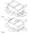
- FIG. 1a shows a perspective view of a franking machine with a removable housing upper part 2, which in the Y direction over a housing lower part 1 is arranged.
- the front 25, the inbox side 27 and the mail exit side (not visible) of the housing top 2 have a slot-shaped opening 21 for a franking Postgut, which can be fed in the Z direction.
- the housing top has a front side 25 towards inclined surface 22, which is suitable to record a - not shown - user interface.
- a lid-shaped flap 3 is arranged on the Housing top 23, which in the X direction to the inclined housing surface 22 connects.
- the housing rear side 26 is suitably formed to a - In the figures 2a, 3a and 4a Shown - locking means to receive, which can lock or unlock the housing parts 1, 2.
- the sectional area A located in the XY plane is shown only in FIG. 1a.
- FIGS. 2a to 4b show an interior view of the franking machine shown, the latter being cut in the XY plane.
- FIG. 1b shows a perspective view of the detachable housing upper part 2 with the slot-shaped opening 21 on the front side 25, the mailing side 27 and the mail exit side (not visible) of the housing upper part 2, with the housing rear side 26, with the inclined housing surface 22 and the housing top side 23.
- the latter is shown without the flap and has an opening 24 bounded by the inclined housing surface 22.
- at least one releasable safety housing part 4 may be provided, which must be released before the housing upper part 2 is removable.
- the detachable upper housing part 2 is open at the bottom and has an identically formed circumferential edge B2, with the exception of the edge H2 on the front side, whose configuration is explained in more detail with reference to FIG. 2c.
- an authorization check must be carried out by the franking machine or meter of the franking machine or via postage meter or meter through a remote data center.
- the authorization check can advantageously take place by means of the data center and the control unit of the franking machine.
- the control unit can distinguish between authorized opening (service, inspection) and unauthorized opening (tampering), in connection with the data transmitted by the data center and a signal detected by a sensor, such as the following: Method for improving the security of postage meters Manipulation, in EP 969 421 A2 (or in US 5,671,146) has already been described.
- a mechanical protection of a printed circuit board is shown, which is arranged in the inner security area of a franking machine and carries a control unit of the Fankiermaschine.
- An upper shell 15, which is correspondingly shaped for protection and support purposes, is disposed above a lower shell 13, which is formed for protection and support purposes, and a printed circuit board 14 on which the components of the inner security area are interconnected.
- the chassis shells 13 and 15 may comprise a group of arranged in a row outer ventilation openings, which are preferably slot-shaped incorporated on the outer edge.
- the lower shell 13 consists of a parallel to the lower housing part 1 shielding and support plate 131 and a rear side of the housing 26 parallel angled rear shield and support plate part 136, which has at least openings for power supply via a power plug cable and for discharging a heated air flow to the outside.
- the safety-related components arranged on the printed circuit board 14 are covered in a box-like manner by the chassis components in the assembled state. In the assembled state, the printed circuit board 14 is located on the front side of the skirt 134 of the lower shell 13. On the circuit board 14, the chassis upper shell 15 is supported with its side walls.
- the upper chassis shell 15 is limited poststromein- or post-stream exit side by a respective side wall 157 and 158 and by a front side wall 155 and by a side wall 152 parallel thereto.
- An inner cavity is divided into a lower cavity 50 and an upper cavity 60 by a plate 156 lying parallel to the shielding and support plate 131.
- the lower cavity 50 is provided for receiving an inner security area control electronics for printing.
- the upper cavity 60 is provided for receiving a pressure mechanism for the mailpiece transport.
- a box 159 is arranged on the upper chassis shell 15, which extends, for example, in the X direction to the rear wall 29 of the housing.
- a box bottom 1590 in the latter at least one opening 1591 for electrical cables of the circuit board 14 in the form of a strip conductor 34 is provided.
- a support frame 10 (FIG. 8) is arranged as a further chassis part for supporting the pressure mechanism.
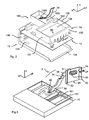
- FIG. 3 shows a protective casing 9 for a strip conductor 34, which from the chassis assembly through the support frame 10 through to a Control electronics unit 38 (not shown) is guided.
- the support frame 10 has a post-current output side limited by sidewalls rectangular boxes with a bottom plate 100 on. The latter points opposite to the X direction near the front an opening 101 for the - not shown - pressure mechanism for transporting a Post item in the transport direction Z on.
- the protective casing 9 consists of a flattened piece of hose 94 and merges at the one end into a cap 90 for covering the control electronics unit 38.
- the tube piece 94 is designed to receive a strip conductor 34 and preferably has a releasable positive connection with the cap 90, which is designed for strain relief.
- a bead-shaped collar 95 is formed on the tube piece 94 and the cap 90 has a hidden opening 91 for the passage of the tube piece 94 through the cap 90 from the side of the control electronics unit 38 to the side of the circuit board 14 hinactedd.
- the cap 90 is adapted for attachment to the printing module 30, the means for attachment being arranged so that the latter are inaccessible from access through the opening 24.
- the cap 90 has, for example, side walls 92, 93 with an opening 96.
- a screw 97 which can be screwed into the opening serves for fastening to the printing module 30.
- the protective sheath 9 leads at the other end to a cover plate 99, which is fastened to the support frame 10 and which is designed for strain relief and for covering the openings in the upper chassis part 15.
- the - not shown - means for fixing the cover plate 99 on the support frame 10 are also arranged inaccessible from access through the opening 24.
- a slot-shaped opening 98 in the cover plate 99 is provided for the passage of the hose piece 94, wherein the cover plate 99 is formed in the opposite direction to the Y direction for strain relief.
- the tubular piece 94 is positively and non-positively connected to the cover plate 99, for example, by a special shape or S-shaped passageway between the cover plate 99 and the box bottom 1590 of the box 159 of the upper chassis shell 15.
- the hose piece 94 is made for example of a particularly resistant plastic and is flexible.
- cover plate 99 and cap 90 can already be formed on the protective casing 9 during production and made of the same material.
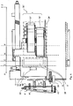
- FIG. 4 shows a variant embodiment with a safety housing part 4 'which denies the user first access to the interior of the mail processing device and with a protective arrangement 8', 9 ', 33', which at any given time has a second restricted access for changing an ink cartridge granted.
- the safety housing part 4 ' covers a releasable further locking means, which is arranged on a wall located in the interior of the safety housing, for example, the housing upper part to manually lock or unlock the safety housing.
- the releasable further locking means is for example a screw 16 'which can be inserted into the support frame 10' or into a chassis part.
- the safety housing part 4 'at least one mechanical locking element 43' is arranged, which consists of a resilient extension arm with a hook nose 432 'at its end, which is engageable with the aforementioned wall located in the interior of the safety housing, wherein the safety housing part 4' only by visible destruction is removable.
- the safety housing part 4 ' preferably has an access protection panel 41' and guiding and locking elements 42 ', 43'.
- the safety housing upper part has an opening 24 ', which allows the user to change an ink cartridge 31', 32 'a second access to the interior of the mail processing device, that the opening 24' closed by a flap is, which is equipped with a stop 39 'which actuates when opening the flap a switch 8', which is arranged inside the safety housing, wherein the power supply to a motor 5 'of the transverse movement means of the printing module 30' is interrupted.
- the latter carries the control electronics for printing, for example a Fankiermaschine and can the power supply of a motor 5 'of Transverse movement means of the print module 30 'interrupt to the print module 30 'to prevent a transverse movement.
- the engine 5 ' is with the Circuit board connected by control.
- the Motor 5 'via the switch 8' electrically connected to the circuit board and can be switched off directly when the flap is open becomes.
- the ink cartridge 31 ', 32' can not then only in the one case be replaced when the latter near the printing position or directly has been positioned in the latter.
- the transversely movable printing module in a position outside the printing position has been moved and the flap is then opened, one in the area the opening 24 'positioned ink cartridge 31', 32 'replaced become.
- An empty or incapable ink cartridge 31 ', 32' may be replaced at any time.
- To protect against manipulation of Postage meter via the opening 24 'and to cover the Control electronics unit 38 'from above prevents the protective cap 33' access to the strip conductor 34 'and the control lines in the Control electronics unit 38 '.
Landscapes
- Physics & Mathematics (AREA)
- General Physics & Mathematics (AREA)
- Accessory Devices And Overall Control Thereof (AREA)
- Devices For Checking Fares Or Tickets At Control Points (AREA)
- Casings For Electric Apparatus (AREA)
Abstract
Description
Es ist weiterhin vorgesehen, dass bei einer mechanischen Freigabe des Zuganges zum Sicherheitsgehäuses eine Ansteuerung eines Tintenstrahldruckkopfes einer Tintenkartusche verhindert wird. Es ist vorteilhaft, wenn durch einen Sensor festgestellt werden kann, dass ein mechanisch freigegebener Zugang zum Wechseln einer Tintenkartusche wieder vor dem Betreiben des postalischen Gerätes verriegelt worden ist. Das Druckmodul kann durch Querbewegungsmittel grundsätzlich verfahren werden:
- aus einer Heimposition in eine Druckposition zum Drucken,
- aus einer Heimposition oder aus der Druckposition in eine Entriegelungsposition zum Freigeben des Sicherheitsgehäuses oder des ersten Zuganges zum Sicherheitsgehäuse oder
- in eine Wechselposition zum Wechseln der Tintenkartusche.
Das Druckmodul kann zuerst in X-Richtung in die Entriegelungsposition und dann entgegengesetzt zur X-Richtung in die Wechselposition für Tintenkartuschen verfahren werden. Somit wird einerseits die Verriegelung des Sicherheitsgehäuses direkt mechanisch freigegeben bzw. ein unverriegelter Zustand eines Zuganges zum Sicherheitsgehäuse liegt vor.
Es ist vorgesehen, dass durch eine Querbewegung des Druckmoduls in die Entriegelungsposition ein Zugang mechanisch freigegeben wird, der zum Wechseln einer Tintenkartusche zugänglich ist.
Es ist vorgesehen,dass der Tintenstrahldruckkopf Bestandteil einer postalischen Tintenkartusche ist, die elektrische und mechanische Besonderheiten aufweist, welche sie von den üblichen Tintenkartuschen unterscheidet, wobei die Besonderheiten zur automatischen und/oder leichten Erkennung der postalischen Tintenkartusche durch das postalische Gerät und/oder durch den Benutzer ausgebildet sind. Weitere elektronische und mechanische Schutzmaßnahmen sind in Verbindung mit dem Druckmodul vorgesehen, das in eine vorbestimmte Wechselposition gebracht werden muss, um einen Austausch der Tintenkartusche zu ermöglichen.
Der Zugang zum Wechseln einer Tintenkartusche wird bereits mechanisch freigegeben, wenn das Druckmodul bei der Querbewegung die Wechselposition durchquert bzw. wenn nur eine Querbewegung des Druckmoduls bis in die Wechselposition erfolgt, also dann, wenn eine unautorisierte Person eine Querbewegung des Druckmoduls beispielsweise vor dem Betreiben des postalischen Gerätes zum Frankieren von Poststücken auslöst. Der Benutzer hat damit nur Zugriff auf Nichtsicherheitsbereiche des Gerätes, beispielsweise zum Wechsel von Verbrauchsmaterial, wie Frankierstreifen oder Tintenkartuschen, zum Batteriewechsel o.a. Im Gehäuseoberteil der Frankiermaschine befindet sich eine entsprechende Öffnung zum Wechseln der Tintenkartusche. Nach Eingabe eines (unautorisierten) Signals wird der Druckwagen mit der Tintenkartusche in eine Wechselposition verschoben, aus der die Tintenkartusche entfernt oder ausgetauscht werden kann. Für den Benutzer ist eine Klappe vorgesehen, welche die vorgenannte Öffnung abdeckt. Die Klappe kann mindestens dann geöffnet werden, falls der Druckwagen in die Wechselposition für die Tintenkartusche oder in die benachbarte zusätzliche Entriegelungsposition verschoben wurde. Alternativ ist die Klappe kein Bestandteil des Sicherheitsgehäuses und/oder kann jederzeit geöffnet oder abgenommen werden. Wenn der Druckwagen zum Drucken in eine Druckposition gebracht ist, verhindert eine Schutzkappe den Zugriff auf die Steuerleitungen während des Druckens. Die Schutzkappe ist am Druckwagen befestigt und verschließt die vorgenannte Öffnung im Gehäuse, entsprechend der Bewegung des Druckwagens in Richtung der Druckposition. Bei jeder anderen Position, in welche der Druckwagen gebracht werden kann, ist die vorgenannte Öffnung durch die Schutzkappe nicht bzw. nicht vollständig verschlossen.
Alternativ ist vorgesehen, dass ein Sicherheitsgehäuseteil dem Benutzer einen ersten Zugang in das Innere des Postverarbeitungsgerätes verwehrt und ein lösbares weiteres Verriegelungsmittel überdeckt, welches an einer im Innerem des Sicherheitsgehäuses gelegenen Wand eines Gehäuseunterteils oder -oberteils des Sicherheitsgehäuse angeordnet ist, um das Sicherheitsgehäuse manuell zu ver- oder entriegeln, dass am Sicherheitsgehäuseteil mindestens ein mechanisches Verriegelungselement angeordnet ist, welches mit einer Hakennase am Ende eines federnden Verlängerungsarms ausgestattet ist, die mit der vorgenannten im Innerem des Sicherheitsgehäuses gelegenen Wand in Eingriff bringbar ist, wobei das Sicherheitsgehäuseteil nur durch sichtbare Zerstörung entfernbar ist, dass das Sicherheitsgehäuseoberteil eine Öffnung aufweist, die dem Benutzer zum Wechseln einer Tintenkartusche einen beschränkten zweiten Zugang in das Innere des Postverarbeitungsgerätes ermöglicht, dass die Öffnung durch eine Klappe verschließbar ist, die mit einem Anschlag ausgestattet ist, der beim Öffnen der Klappe einen Schalter betätigt, der im Innerem des Sicherheitsgehäuses angeordnet ist, wobei die Stromversorgung eines Motors der Querbewegungsmittel des Druckmoduls unterbrochen wird sowie dass am Druckmodul eine Schutzummantelung und eine Schutzkappe zum Verhindern eines unberechtigten Zugriffs auf den Bandleiter und auf die Ansteuerelektronikeinheit befestigt sind.
Vorteilhafte Weiterbildungen der Erfindung sind in den Unteransprüchen gekennzeichnet bzw. werden nachstehend zusammen mit der Beschreibung der bevorzugten Ausführung der Erfindung anhand der Figuren näher dargestellt. Es zeigen:
Das abnehmbare Gehäuseoberteil 2 ist nach unten offen und hat einen gleich ausgebildeten umlaufenden Rand B2, mit Ausnahme des Randes H2 auf der Frontseite, dessen Ausgestaltung anhand der Fig. 2c näher erläutert wird. Bevor das Gehäuseoberteil 2 abgenommen werden kann, muß eine Autorisationsprüfung durch die Frankiermaschine bzw. Meter der Frankiermaschine oder via Frankiermaschine bzw. Meter durch eine entfernte Datenzentrale durchgeführt weden. Die Autorisationsprüfung kann vorteilhaft mittels der Datenzentrale und der Steuereinheit der Frankiermaschine erfolgen. Die Steuereinheit kann zwischen autorisiertem Öffnen (Service, Inspektion) und unautorisiertem Öffnen (Manipulationsabsicht) unterscheiden, in Verbindung mit den von der Datenzentrale übermittelten Daten und einem über einen Sensor detektierten Signal, wie das unter dem Titel: Verfahren zur Verbesserung der Sicherheit von Frankiermaschinen gegen Manipulation, im EP 969 421 A2 (bzw. im US 5.671.146) bereits beschrieben wurde.
Die Chassisoberschale 15 wird poststromein- bzw poststromausgangsseitig durch je eine Seitenwand 157 bzw. 158 sowie durch eine Frontseitenwand 155 und durch eine dazu parallele Seitenwand 152 begrenzt. Eine innen liegende Kavität wird durch eine zum Abschirm- und Stützblech 131 parallel liegende Platte 156 in eine untere Kavität 50 und eine obere Kavität 60 aufgeteilt. Die untere Kavität 50 ist zur Aufnahme einer im inneren Sicherheitsbereich gelegenen Steuerungselektronik für das Drucken vorgesehen. Die obere Kavität 60 ist zur Aufnahme einer Andruckmechanik für den Poststücktransport vorgesehen. Zusätzlich wird ein Kasten 159 an der Chassisoberschale 15 angeordnet, der sich beispielsweise in X-Richtung bis zur Gehäuserückwand 29 erstreckt. Wenn der Kasten 159, wie gezeigt ist, einen Kastenboden 1590 aufweist, dann ist im letzteren mindestens eine Öffnung 1591 für elektrische Kabel der Leiterplatte 14 in Form eines Bandleiters 34 vorgesehen. Oberhalb der Chassisoberschale 15 wird ein Stützrahmen 10 (Fig. 8) als weiteres Chassisteil zum Abstützen der Druckmechanik angeordnet.
Die Schutzummantelung 9 führt an dem anderen Ende zu einer Abdeckplatte 99, die am Stützrahmen 10 befestigbar ist und die zur Zugentlastung und zur Abdeckung der Öffnungen im oberen Chassisteil 15 ausgebildet ist. Die - nicht näher dargestellten - Mittel zur Befestigung der Abdeckplatte 99 am Stützrahmen 10 sind vom Zugang durch die Öffnung 24 ebenfalls unzugänglich angeordnet. Eine schlitzförmige Öffnung 98 in der Abdeckplatte 99 ist zur Hindurchführung des Schlauchstückes 94 vorgesehen, wobei die Abdeckplatte 99 auf der zur Y-Richtung entgegengesetzten Richtung zur Zugentlastung ausgebildet ist. Das Schlauchstück 94 wird beispielsweise durch eine besondere Formgebung oder S-förmige Hindurchführung zwischen der Abdeckplatte 99 und dem Kastenboden 1590 des Kastens 159 der Chassisoberschale 15 form- und kraftschlüssig mit der Abdeckplatte 99 verbunden. Das Schlauchstück 94 wird beispielsweise aus einem besonders widerstandsfähigen Kunstoff hergestellt und ist flexibel ausgebildet.
Alternativ können Abdeckplatte 99 und Kappe 90 an der Schutzummantelung 9 bereits während der Herstellung angeformt und aus dem gleichen Material hergestellt werden.
In Kombination mit dieser alternativen Ausführungsvariante ist weiterhin vorgesehen, dass das Sicherheitsgehäuseoberteil eine Öffnung 24' aufweist, die dem Benutzer zum Wechseln einer Tintenkartusche 31', 32' einen zweiten Zugang in das Innere des Postverarbeitungsgerätes ermöglicht, dass die Öffnung 24' durch eine Klappe verschließbar ist, die mit einem Anschlag 39' ausgestattet ist, der beim Öffnen der Klappe einen Schalter 8' betätigt, der im Innerem des Sicherheitsgehäuses angeordnet ist, wobei die Stromversorgung eines Motors 5' der Querbewegungsmittel des Druckmoduls 30' unterbrochen wird.
Claims (8)
- Verfahren zur mechanischen Freigabe eines Zuganges eines Sicherheitsgehäuses, mit einem auswechselbaren Tintenkartusche mit integriertem Druckkopf auf einem Druckmodul, der wahlweise in eine Druckposition zum Drucken oder in eine Wechselposition zum Wechseln der Tintenkartusche via dem Zugang verfahren werden kann, gekenn-zeichnet durcheine Querbewegung des Druckmoduls (30) mittels Querbewegungsmittel in die Druckposition P, wobei eine Öffnung (24) im Sicherheitsgehäuse durch das Verfahren des Druckmoduls in die Druckposition P mechanisch verschlossen wird,einen Transport eines Poststückes während des Druckens in Poststücktransportrichtung Z,eine Querbewegung des Druckmoduls (30) mittels Querbewegungsmittel, wobei das Druckmodul (30) in die Wechselposition C quer zur Poststücktransportrichtung Z gebracht wird, wodurch der Zugang zur Öffnung (24) mechanisch freigegeben wird, die Tintenkartusche mit integriertem Druckkopf auszuwechseln.
- Anordnung für ein Sicherheitsgehäuse eines druckenden Postverarbeitungsgerätes, das mit einer mechanischen Verriegelungsvorrichtung ausgestattet ist, mit einem Druckmodul (30), das durch Querbewegungsmittel (5, 6, 7) querbeweglich zur Poststücktransportrichtung (Z) angeordnet ist, dadurch gekennzeichnet, dass ein Sicherheitsgehäuseteil (4) vorgesehen ist, das dem Benutzer einen ersten Zugang in das Innere des Postverarbeitungsgerätes verwehrt und ein lösbares weiteres Verriegelungsmittel überdeckt, welches an einer im Innerem des Sicherheitsgehäuses gelegenen Wand eines Gehäuseunterteils (1) oder eines Gehäuseoberteils (2) des Sicherheitsgehäuse angeordnet ist, um das Sicherheitsgehäuse manuell zu ver- oder entriegeln, dass am Sicherheitsgehäuseteil (4) mindestens ein mechanisches Verriegelungselement (43) angeordnet ist, welches mit einer Hakennase (432) am Ende eines federnden Verlängerungsarms ausgestattet ist, die mit der vorgenannten im Innerem des Sicherheitsgehäuses gelegenen Wand in Eingriff bringbar ist, wobei das Sicherheitsgehäuseteil (4) nur durch sichtbare Zerstörung entfernbar ist,
dass das Sicherheitsgehäuseoberteil (2) eine Öffnung (24) aufweist, die dem Benutzer zum Wechseln einer Tintenkartusche einen beschränkten zweiten Zugang in das Innere des Postverarbeitungsgerätes ermöglicht, dass die Öffnung (24) durch eine Klappe (3) verschließbar ist, die mit einem Anschlag (39) ausgestattet ist, der beim Öffnen der Klappe (3) einen Schalter (8) betätigt, der im Innerem des Sicherheitsgehäuses angeordnet ist, wobei die Stromversorgung eines Motors (5) der Querbewegungsmittel des Druckmoduls (30) unterbrochen wird sowie dass zum Verhindern eines unberechtigten Zugriffs auf den Bandleiter (34) und auf die Ansteuerelektronikeinheit (38) eine Schutzummantelung (9) und eine Schutzkappe (33) am Druckmodul (30) befestigt sind. - Anordnung, nach Anspruch 2, dadurch gekennzeichnet, dass die Schutzummantelung (9) ein Schlauchstück (94) aufweist, an deren Enden eine Abdeckplatte (99) und eine Kappe (90) befestigbar sind, wobei die Kappe (90) zum Verhindern eines unberechtigten Zugriffs auf die Ansteuerelektronikeinheit (38) ausgeformt ist.
- Anordnung, nach Anspruch 2, dadurch gekennzeichnet, dass das Schlauchstück (94) für die Aufnahme des Bandleiters (34) ausgebildet und aus einem besonders widerstandsfähigen Kunstoff hergestellt und flexibel ausgebildet ist.
- Anordnung, nach Anspruch 2, dadurch gekennzeichnet, dass das Schlauchstück (94) eine lösbare formschlüssige Verbindung mit der Kappe (90) aufweist, die zur Zugentlastung ausgebildet ist, dass die Kappe (90) zur Befestigung am Druckmodul (30) ausgebildet, wobei die Mittel zur Befestigung so angeordnet sind, dass letztere vom Zugang durch die Öffnung (24) unzugänglich sind.
- Anordnung, nach Anspruch 2, dadurch gekennzeichnet, dass die Schutzummantelung (9) ein Schlauchstück (94) aufweist, an deren Enden eine Abdeckplatte (99) und Kappe (90) während der Herstellung angeformt und aus dem gleichen Material hergestellt werden.
- Anordnung, nach Anspruch 2, dadurch gekennzeichnet, dass die Kappe (90) und die Abdeckplatte (99) zur Hindurchführung des Schlauchstückes (94) und zur Zugentlastung ausgebildet sind.
- Anordnung, nach Anspruch 2, dadurch gekennzeichnet, dass der Schalter (8) ein Mikroschalter ist.
Applications Claiming Priority (3)
| Application Number | Priority Date | Filing Date | Title |
|---|---|---|---|
| DE2001149210 DE10149210A1 (de) | 2001-10-02 | 2001-10-02 | Verfahren und Anordnung zum Öffnen eines Sicherheitsgehäuses |
| DE10164527A DE10164527A1 (de) | 2001-12-15 | 2001-12-15 | Anordnung zum Schutz eines Druckmoduls in einem Postverarbeitungsgerät |
| EP02090335A EP1300807B8 (de) | 2001-10-02 | 2002-09-17 | Verfahren und Anordnung zum Öffnen eines Sicherheitsgehäuses |
Related Parent Applications (2)
| Application Number | Title | Priority Date | Filing Date |
|---|---|---|---|
| EP02090335.7 Division | 2002-09-17 | ||
| EP02090335A Division EP1300807B8 (de) | 2001-10-02 | 2002-09-17 | Verfahren und Anordnung zum Öffnen eines Sicherheitsgehäuses |
Publications (4)
| Publication Number | Publication Date |
|---|---|
| EP1607912A2 true EP1607912A2 (de) | 2005-12-21 |
| EP1607912A3 EP1607912A3 (de) | 2006-02-08 |
| EP1607912A8 EP1607912A8 (de) | 2006-03-01 |
| EP1607912B1 EP1607912B1 (de) | 2013-03-20 |
Family
ID=26010304
Family Applications (2)
| Application Number | Title | Priority Date | Filing Date |
|---|---|---|---|
| EP05020434A Expired - Lifetime EP1607912B1 (de) | 2001-10-02 | 2002-09-17 | Verfahren und Anordnung zum Öffnen eines Sicherheitsgehäuses |
| EP02090335A Expired - Lifetime EP1300807B8 (de) | 2001-10-02 | 2002-09-17 | Verfahren und Anordnung zum Öffnen eines Sicherheitsgehäuses |
Family Applications After (1)
| Application Number | Title | Priority Date | Filing Date |
|---|---|---|---|
| EP02090335A Expired - Lifetime EP1300807B8 (de) | 2001-10-02 | 2002-09-17 | Verfahren und Anordnung zum Öffnen eines Sicherheitsgehäuses |
Country Status (3)
| Country | Link |
|---|---|
| US (2) | US6811337B2 (de) |
| EP (2) | EP1607912B1 (de) |
| DE (1) | DE50205263D1 (de) |
Families Citing this family (15)
| Publication number | Priority date | Publication date | Assignee | Title |
|---|---|---|---|---|
| JP4241013B2 (ja) * | 2002-11-26 | 2009-03-18 | 富士ゼロックス株式会社 | 画像形成装置並びにこれに用いられるフレーム構造及びその製造方法 |
| US6942144B2 (en) * | 2002-11-26 | 2005-09-13 | Neopost Industrie Sa | Secure remote access to metering product enclosure |
| USD523072S1 (en) * | 2004-06-11 | 2006-06-13 | Shin Heung Precision, Ltd. | Printer |
| USD527413S1 (en) * | 2004-08-11 | 2006-08-29 | Axiohm Transaction Solutions, Inc. | Transaction printer |
| DE202004015278U1 (de) * | 2004-10-01 | 2004-12-16 | Francotyp-Postalia Ag & Co. Kg | Kassettenaufnahmeeinrichtung mit Zustandserkennung für ein druckendes Postverarbeitungsgerät |
| USD558819S1 (en) * | 2006-01-16 | 2008-01-01 | Seiko Epson Corporation | Printer |
| USD559900S1 (en) * | 2006-01-16 | 2008-01-15 | Seiko Epson Corporation | Printer |
| DE102007060733A1 (de) | 2007-12-17 | 2009-06-25 | Francotyp-Postalia Gmbh | Vorrichtung zum Wechseln von Tintenkartuschen |
| DE102008030530B4 (de) | 2008-06-27 | 2010-09-30 | Francotyp-Postalia Gmbh | Tintenkartuschenaufnahme |
| USD640735S1 (en) * | 2009-12-28 | 2011-06-28 | Seiko Epson Corporation | Printer |
| DE202012002510U1 (de) | 2012-03-02 | 2012-03-28 | Francotyp-Postalia Gmbh | Druckergerät |
| JP1617644S (de) * | 2018-03-30 | 2018-11-12 | ||
| DE202018102465U1 (de) | 2018-05-03 | 2018-05-14 | Francotyp-Postalia Gmbh | Gutverarbeitungsgerät mit einem Tintenstrahldruckkopf |
| CN110252850B (zh) * | 2019-07-18 | 2024-01-26 | 江苏舒尔驰精密金属成形有限公司 | 一种卷板下料机 |
| US11048205B1 (en) * | 2020-02-10 | 2021-06-29 | Datamax-O'neil Corporation | Safety mechanism for printing apparatus |
Family Cites Families (21)
| Publication number | Priority date | Publication date | Assignee | Title |
|---|---|---|---|---|
| US4099049A (en) * | 1976-11-10 | 1978-07-04 | Pitney-Bowes, Inc. | Ascending register lockout system for a postage meter |
| US4484307A (en) * | 1979-05-09 | 1984-11-20 | F.M.E. Corporation | Electronic postage meter having improved security and fault tolerance features |
| GB2169875B (en) * | 1985-01-19 | 1988-09-14 | Francotyp Postalia Gmbh | Improvements in ribbon cassettes |
| US4907018A (en) * | 1988-11-21 | 1990-03-06 | Hewlett-Packard Company | Printhead-carriage alignment and electrical interconnect lock-in mechanism |
| US4922817A (en) * | 1988-07-13 | 1990-05-08 | Pitney Bowes Inc. | Secure shutter locking arrangement for a postage meter |
| US5365312A (en) * | 1988-07-25 | 1994-11-15 | Mannesmann Ag | Arrangement for printer equipment for monitoring reservoirs that contain printing medium |
| US5093560A (en) * | 1990-10-31 | 1992-03-03 | Pitney Bowes Inc. | Locking device for removable postage meter |
| CH683652A5 (de) * | 1992-03-10 | 1994-04-15 | Frama Ag | Frankiermaschine. |
| US5561450A (en) * | 1992-09-30 | 1996-10-01 | Pitney Bowes Inc. | Apparatus for mounting an ink jet cartridge on a support therefor |
| JP3210098B2 (ja) * | 1992-10-30 | 2001-09-17 | キヤノン株式会社 | インクジェット記録装置およびインクジェット記録方法 |
| US5424760A (en) * | 1993-02-08 | 1995-06-13 | Eastman Kodak Company | Cover interlock mechasnism for a thermal printer locks cover while printing |
| DE4344476A1 (de) * | 1993-12-21 | 1995-06-22 | Francotyp Postalia Gmbh | Verfahren zur Verbesserung der Sicherheit von Frankiermaschinen |
| US5467709A (en) * | 1994-12-22 | 1995-11-21 | Pitney Bowes Inc. | Mailing machine utilizing ink jet printer |
| US5689098A (en) * | 1995-05-26 | 1997-11-18 | Ascom Hasler Mailing Systems Ag | Postage meter with improved postal lock |
| JP3305611B2 (ja) * | 1997-03-10 | 2002-07-24 | シャープ株式会社 | 画像形成装置 |
| GB9709049D0 (en) | 1997-05-02 | 1997-06-25 | Neopost Ltd | Postage meter with removable print head |
| GB9709050D0 (en) | 1997-05-02 | 1997-06-25 | Neopost Ltd | Postage meter with removable print head |
| GB9709051D0 (en) | 1997-05-02 | 1997-06-25 | Neopost Ltd | Postage meter with removable print head |
| EP0881086B1 (de) * | 1997-05-28 | 2005-04-27 | Neopost Limited | Sicheres Drückgerät mit einem abnehmbaren Druckkopf |
| US5956051A (en) | 1997-05-29 | 1999-09-21 | Pitney Bowes Inc. | Disabling a mailing machine when a print head is not installed |
| DE19748954A1 (de) * | 1997-10-29 | 1999-05-06 | Francotyp Postalia Gmbh | Verfahren für eine digital druckende Frankiermaschine zur Erzeugung und Überprüfung eines Sicherheitsabdruckes |
-
2002
- 2002-09-17 EP EP05020434A patent/EP1607912B1/de not_active Expired - Lifetime
- 2002-09-17 DE DE50205263T patent/DE50205263D1/de not_active Expired - Lifetime
- 2002-09-17 EP EP02090335A patent/EP1300807B8/de not_active Expired - Lifetime
- 2002-09-20 US US10/247,855 patent/US6811337B2/en not_active Expired - Fee Related
-
2004
- 2004-05-19 US US10/850,416 patent/US7033096B2/en not_active Expired - Fee Related
Also Published As
| Publication number | Publication date |
|---|---|
| EP1607912B1 (de) | 2013-03-20 |
| EP1607912A8 (de) | 2006-03-01 |
| US20030170064A1 (en) | 2003-09-11 |
| US20040213621A1 (en) | 2004-10-28 |
| US7033096B2 (en) | 2006-04-25 |
| EP1300807B8 (de) | 2006-03-15 |
| EP1300807A2 (de) | 2003-04-09 |
| EP1300807B1 (de) | 2005-12-14 |
| DE50205263D1 (de) | 2006-01-19 |
| US6811337B2 (en) | 2004-11-02 |
| EP1607912A3 (de) | 2006-02-08 |
| EP1300807A3 (de) | 2003-05-21 |
Similar Documents
| Publication | Publication Date | Title |
|---|---|---|
| EP1607912B1 (de) | Verfahren und Anordnung zum Öffnen eines Sicherheitsgehäuses | |
| DE69510833T2 (de) | Frankiermaschine mit einem gesicherten und einem ungesicherten Modul | |
| DE10011192A1 (de) | Frankiermaschine mit abgesichertem Druckkopf | |
| DE3613007B4 (de) | System zur Ermittlung von nicht-abgerechneten Drucken | |
| DE60025493T2 (de) | Sicherungsschrank, sicherungseinheit kombiniert mit einer aufnahmeeinheit, und geldautomat mit einer solchen einrichtung | |
| EP1320076B1 (de) | Anordnung zum Schutz eines Druckmoduls in einem Postverarbeitungsgerät | |
| EP1103924B1 (de) | Verfahren zum Schutz eines Gerätes vor einem Betreiben mit unzulässigem Verbrauchsmaterial und Anordnung zur Durchführung des Verfahrens | |
| DE69923408T2 (de) | Verfahren und Vorrichtung zur dynamischen Bestimmung der Druckposition für ein Postwertzeichen in einen Dokument | |
| DE3729342A1 (de) | Sicherheitsdrucker fuer ein wertdrucksystem | |
| DE19958948B4 (de) | Verfahren zur Bestimmung der Anzahl von mit einer Tintenrestmenge ausführbaren Drucken und Vorrichtung zur Durchführung des Verfahrens | |
| DE69829911T2 (de) | Sicheres Drückgerät mit einem abnehmbaren Druckkopf | |
| DE3820852C2 (de) | ||
| DE3627124A1 (de) | Frankiermaschinen-verriegelungssystem | |
| DE69803975T2 (de) | Gesicherter digitaler Frankier-Druckmodul | |
| EP1103925B1 (de) | Verfahren zum Piraterieschutz eines Gerätes und Anordnung zur Durchführung des Verfahrens | |
| DE10164526A1 (de) | Sicherheitschassis | |
| EP1103923A2 (de) | Verfahren zum automatischen Bestellen von Verbrauchsmaterial und Anordnung zur Durchführung des Verfahrens | |
| US6466922B1 (en) | Postage meter with removable print head and having means to control access to the print head | |
| DE10149210A1 (de) | Verfahren und Anordnung zum Öffnen eines Sicherheitsgehäuses | |
| DE69924946T2 (de) | Verfahren und Vorrichtung zum dynamischen Anordnen und Drucken von einer Vielzahl von Postwertzeichen auf einem Poststück | |
| DE202018102465U1 (de) | Gutverarbeitungsgerät mit einem Tintenstrahldruckkopf | |
| DE20211108U1 (de) | Anordnung eines Sicherheitsmoduls in einer Frankiermaschine | |
| EP1202223A2 (de) | Postmachine und Verfahren zu deren Initialisierung | |
| EP1615174A2 (de) | Anordnung einer kommunikationseinheit in einem gerät | |
| DE4344503A1 (de) | Mietfachanlage |
Legal Events
| Date | Code | Title | Description |
|---|---|---|---|
| PUAI | Public reference made under article 153(3) epc to a published international application that has entered the european phase |
Free format text: ORIGINAL CODE: 0009012 |
|
| AC | Divisional application: reference to earlier application |
Ref document number: 1300807 Country of ref document: EP Kind code of ref document: P |
|
| AK | Designated contracting states |
Kind code of ref document: A2 Designated state(s): CH DE FR GB IT LI |
|
| AX | Request for extension of the european patent |
Extension state: AL LT LV MK RO SI |
|
| PUAL | Search report despatched |
Free format text: ORIGINAL CODE: 0009013 |
|
| RAP1 | Party data changed (applicant data changed or rights of an application transferred) |
Owner name: FRANCOTYP-POSTALIA GMBH |
|
| AK | Designated contracting states |
Kind code of ref document: A3 Designated state(s): CH DE FR GB IT LI |
|
| AX | Request for extension of the european patent |
Extension state: AL LT LV MK RO SI |
|
| 17P | Request for examination filed |
Effective date: 20060621 |
|
| 17Q | First examination report despatched |
Effective date: 20060731 |
|
| AKX | Designation fees paid |
Designated state(s): CH DE FR GB IT LI |
|
| GRAP | Despatch of communication of intention to grant a patent |
Free format text: ORIGINAL CODE: EPIDOSNIGR1 |
|
| GRAS | Grant fee paid |
Free format text: ORIGINAL CODE: EPIDOSNIGR3 |
|
| GRAA | (expected) grant |
Free format text: ORIGINAL CODE: 0009210 |
|
| AC | Divisional application: reference to earlier application |
Ref document number: 1300807 Country of ref document: EP Kind code of ref document: P |
|
| AK | Designated contracting states |
Kind code of ref document: B1 Designated state(s): CH DE FR GB IT LI |
|
| REG | Reference to a national code |
Ref country code: GB Ref legal event code: FG4D Free format text: NOT ENGLISH |
|
| REG | Reference to a national code |
Ref country code: CH Ref legal event code: EP |
|
| REG | Reference to a national code |
Ref country code: DE Ref legal event code: R096 Ref document number: 50215728 Country of ref document: DE Effective date: 20130516 |
|
| PLBE | No opposition filed within time limit |
Free format text: ORIGINAL CODE: 0009261 |
|
| STAA | Information on the status of an ep patent application or granted ep patent |
Free format text: STATUS: NO OPPOSITION FILED WITHIN TIME LIMIT |
|
| 26N | No opposition filed |
Effective date: 20140102 |
|
| REG | Reference to a national code |
Ref country code: DE Ref legal event code: R097 Ref document number: 50215728 Country of ref document: DE Effective date: 20140102 |
|
| REG | Reference to a national code |
Ref country code: DE Ref legal event code: R081 Ref document number: 50215728 Country of ref document: DE Owner name: FRANCOTYP-POSTALIA GMBH, DE Free format text: FORMER OWNER: FRANCOTYP-POSTALIA BETEILIGUNGS AG, 16547 BIRKENWERDER, DE Effective date: 20130320 Ref country code: DE Ref legal event code: R081 Ref document number: 50215728 Country of ref document: DE Owner name: FRANCOTYP-POSTALIA GMBH, DE Free format text: FORMER OWNER: FRANCOTYP-POSTALIA GMBH, 16547 BIRKENWERDER, DE Effective date: 20150330 |
|
| REG | Reference to a national code |
Ref country code: FR Ref legal event code: PLFP Year of fee payment: 14 |
|
| PGFP | Annual fee paid to national office [announced via postgrant information from national office to epo] |
Ref country code: FR Payment date: 20150626 Year of fee payment: 14 |
|
| PGFP | Annual fee paid to national office [announced via postgrant information from national office to epo] |
Ref country code: DE Payment date: 20150718 Year of fee payment: 14 Ref country code: GB Payment date: 20150917 Year of fee payment: 14 Ref country code: CH Payment date: 20150918 Year of fee payment: 14 |
|
| PGFP | Annual fee paid to national office [announced via postgrant information from national office to epo] |
Ref country code: IT Payment date: 20150924 Year of fee payment: 14 |
|
| REG | Reference to a national code |
Ref country code: DE Ref legal event code: R119 Ref document number: 50215728 Country of ref document: DE |
|
| REG | Reference to a national code |
Ref country code: CH Ref legal event code: PL |
|
| GBPC | Gb: european patent ceased through non-payment of renewal fee |
Effective date: 20160917 |
|
| REG | Reference to a national code |
Ref country code: FR Ref legal event code: ST Effective date: 20170531 |
|
| PG25 | Lapsed in a contracting state [announced via postgrant information from national office to epo] |
Ref country code: GB Free format text: LAPSE BECAUSE OF NON-PAYMENT OF DUE FEES Effective date: 20160917 Ref country code: CH Free format text: LAPSE BECAUSE OF NON-PAYMENT OF DUE FEES Effective date: 20160930 Ref country code: DE Free format text: LAPSE BECAUSE OF NON-PAYMENT OF DUE FEES Effective date: 20170401 Ref country code: FR Free format text: LAPSE BECAUSE OF NON-PAYMENT OF DUE FEES Effective date: 20160930 Ref country code: LI Free format text: LAPSE BECAUSE OF NON-PAYMENT OF DUE FEES Effective date: 20160930 |
|
| PG25 | Lapsed in a contracting state [announced via postgrant information from national office to epo] |
Ref country code: IT Free format text: LAPSE BECAUSE OF NON-PAYMENT OF DUE FEES Effective date: 20160917 |