EP1606149B1 - Sicherheitsberechtigungssystem - Google Patents
Sicherheitsberechtigungssystem Download PDFInfo
- Publication number
- EP1606149B1 EP1606149B1 EP04722899.4A EP04722899A EP1606149B1 EP 1606149 B1 EP1606149 B1 EP 1606149B1 EP 04722899 A EP04722899 A EP 04722899A EP 1606149 B1 EP1606149 B1 EP 1606149B1
- Authority
- EP
- European Patent Office
- Prior art keywords
- user
- communication link
- vehicle
- communication
- functioning
- Prior art date
- Legal status (The legal status is an assumption and is not a legal conclusion. Google has not performed a legal analysis and makes no representation as to the accuracy of the status listed.)
- Expired - Lifetime
Links
- 238000013475 authorization Methods 0.000 title claims description 73
- 230000006854 communication Effects 0.000 claims description 182
- 238000004891 communication Methods 0.000 claims description 182
- 230000005540 biological transmission Effects 0.000 claims description 78
- 230000000694 effects Effects 0.000 claims description 54
- 230000005764 inhibitory process Effects 0.000 claims description 21
- 230000000977 initiatory effect Effects 0.000 claims description 20
- 239000000446 fuel Substances 0.000 claims description 17
- 230000005855 radiation Effects 0.000 claims description 15
- 238000012546 transfer Methods 0.000 claims description 15
- 230000000295 complement effect Effects 0.000 claims description 12
- 230000002123 temporal effect Effects 0.000 claims description 12
- 230000001133 acceleration Effects 0.000 claims description 10
- 230000004044 response Effects 0.000 claims description 6
- 230000007175 bidirectional communication Effects 0.000 claims description 5
- 230000008859 change Effects 0.000 claims description 4
- 230000002401 inhibitory effect Effects 0.000 claims description 4
- 238000005096 rolling process Methods 0.000 claims description 3
- 230000006870 function Effects 0.000 description 42
- 238000012545 processing Methods 0.000 description 24
- 230000001413 cellular effect Effects 0.000 description 10
- 230000003111 delayed effect Effects 0.000 description 9
- 238000000926 separation method Methods 0.000 description 9
- 238000010586 diagram Methods 0.000 description 7
- 238000003860 storage Methods 0.000 description 7
- 230000008901 benefit Effects 0.000 description 4
- 238000000034 method Methods 0.000 description 4
- 230000006855 networking Effects 0.000 description 3
- 239000013589 supplement Substances 0.000 description 3
- 230000009471 action Effects 0.000 description 2
- 230000006378 damage Effects 0.000 description 2
- 206010013395 disorientation Diseases 0.000 description 2
- 238000005516 engineering process Methods 0.000 description 2
- 230000008092 positive effect Effects 0.000 description 2
- 239000004065 semiconductor Substances 0.000 description 2
- 230000035945 sensitivity Effects 0.000 description 2
- 230000008054 signal transmission Effects 0.000 description 2
- 230000001360 synchronised effect Effects 0.000 description 2
- ATJFFYVFTNAWJD-UHFFFAOYSA-N Tin Chemical compound [Sn] ATJFFYVFTNAWJD-UHFFFAOYSA-N 0.000 description 1
- QGLZXHRNAYXIBU-WEVVVXLNSA-N aldicarb Chemical compound CNC(=O)O\N=C\C(C)(C)SC QGLZXHRNAYXIBU-WEVVVXLNSA-N 0.000 description 1
- 230000003466 anti-cipated effect Effects 0.000 description 1
- 230000006399 behavior Effects 0.000 description 1
- 239000003990 capacitor Substances 0.000 description 1
- 230000006835 compression Effects 0.000 description 1
- 238000007906 compression Methods 0.000 description 1
- 238000012790 confirmation Methods 0.000 description 1
- 239000000470 constituent Substances 0.000 description 1
- 230000001351 cycling effect Effects 0.000 description 1
- 230000001934 delay Effects 0.000 description 1
- 238000013461 design Methods 0.000 description 1
- 229920002457 flexible plastic Polymers 0.000 description 1
- 230000009454 functional inhibition Effects 0.000 description 1
- 238000011065 in-situ storage Methods 0.000 description 1
- 238000002347 injection Methods 0.000 description 1
- 239000007924 injection Substances 0.000 description 1
- 238000007689 inspection Methods 0.000 description 1
- 239000007788 liquid Substances 0.000 description 1
- 238000007726 management method Methods 0.000 description 1
- 239000000463 material Substances 0.000 description 1
- 230000003864 performance function Effects 0.000 description 1
- 230000000737 periodic effect Effects 0.000 description 1
- 230000008569 process Effects 0.000 description 1
- 230000001105 regulatory effect Effects 0.000 description 1
- 230000002463 transducing effect Effects 0.000 description 1
Images


Classifications
-
- B—PERFORMING OPERATIONS; TRANSPORTING
- B60—VEHICLES IN GENERAL
- B60R—VEHICLES, VEHICLE FITTINGS, OR VEHICLE PARTS, NOT OTHERWISE PROVIDED FOR
- B60R25/00—Fittings or systems for preventing or indicating unauthorised use or theft of vehicles
- B60R25/01—Fittings or systems for preventing or indicating unauthorised use or theft of vehicles operating on vehicle systems or fittings, e.g. on doors, seats or windscreens
- B60R25/04—Fittings or systems for preventing or indicating unauthorised use or theft of vehicles operating on vehicle systems or fittings, e.g. on doors, seats or windscreens operating on the propulsion system, e.g. engine or drive motor
- B60R25/042—Fittings or systems for preventing or indicating unauthorised use or theft of vehicles operating on vehicle systems or fittings, e.g. on doors, seats or windscreens operating on the propulsion system, e.g. engine or drive motor operating on the fuel supply
-
- B—PERFORMING OPERATIONS; TRANSPORTING
- B60—VEHICLES IN GENERAL
- B60R—VEHICLES, VEHICLE FITTINGS, OR VEHICLE PARTS, NOT OTHERWISE PROVIDED FOR
- B60R25/00—Fittings or systems for preventing or indicating unauthorised use or theft of vehicles
- B60R25/10—Fittings or systems for preventing or indicating unauthorised use or theft of vehicles actuating a signalling device
- B60R25/102—Fittings or systems for preventing or indicating unauthorised use or theft of vehicles actuating a signalling device a signal being sent to a remote location, e.g. a radio signal being transmitted to a police station, a security company or the owner
-
- B—PERFORMING OPERATIONS; TRANSPORTING
- B60—VEHICLES IN GENERAL
- B60R—VEHICLES, VEHICLE FITTINGS, OR VEHICLE PARTS, NOT OTHERWISE PROVIDED FOR
- B60R25/00—Fittings or systems for preventing or indicating unauthorised use or theft of vehicles
- B60R25/20—Means to switch the anti-theft system on or off
- B60R25/24—Means to switch the anti-theft system on or off using electronic identifiers containing a code not memorised by the user
- B60R25/241—Means to switch the anti-theft system on or off using electronic identifiers containing a code not memorised by the user whereby access privileges are related to the identifiers
-
- B—PERFORMING OPERATIONS; TRANSPORTING
- B60—VEHICLES IN GENERAL
- B60R—VEHICLES, VEHICLE FITTINGS, OR VEHICLE PARTS, NOT OTHERWISE PROVIDED FOR
- B60R2325/00—Indexing scheme relating to vehicle anti-theft devices
- B60R2325/10—Communication protocols, communication systems of vehicle anti-theft devices
- B60R2325/101—Bluetooth
-
- B—PERFORMING OPERATIONS; TRANSPORTING
- B60—VEHICLES IN GENERAL
- B60R—VEHICLES, VEHICLE FITTINGS, OR VEHICLE PARTS, NOT OTHERWISE PROVIDED FOR
- B60R2325/00—Indexing scheme relating to vehicle anti-theft devices
- B60R2325/10—Communication protocols, communication systems of vehicle anti-theft devices
- B60R2325/105—Radio frequency identification data [RFID]
-
- B—PERFORMING OPERATIONS; TRANSPORTING
- B60—VEHICLES IN GENERAL
- B60R—VEHICLES, VEHICLE FITTINGS, OR VEHICLE PARTS, NOT OTHERWISE PROVIDED FOR
- B60R2325/00—Indexing scheme relating to vehicle anti-theft devices
- B60R2325/20—Communication devices for vehicle anti-theft devices
- B60R2325/205—Mobile phones
Definitions
- This invention relates to security systems and particularly to confining correct operation of functional apparatus to the presence of an authorised user and more particularly to disabling functioning apparatus separated from the authorised user.
- the invention is concerned with apparatus which functions under the direct control of an operator as, or on behalf of, an authorised user and in this respect, as least for convenience in discussion of the background to the invention, a suitably authorised operator and an authorised user are considered synonymous, although they need not be.
- the invention is concerned particularly, but not exclusively, with functional apparatus which is moveable insofar as the apparatus or a constituent thereof can be removed to a place unknown to the authorised user. It concerns apparatus which is physically in the possession of the authorised user, carried thereby (such as a cellular telephone or a computing device) or vice versa (such as a motor vehicle), and apparatus function-controlling devices, conveniently herein called “key devices”, which themselves may constitute functional apparatus with a limited degree of functionality required to initiate operation of apparatus, and which apparatus or devices may nevertheless be snatched from the authorised user as a criminal act predicated upon the element of surprise and/or menace, where the speed by which the authorised user, or victim, is deprived thereof renders the criminal less likely to be identifiable and/or the victim less likely to resist and increase the seriousness of the crime with personal violence.
- key devices conveniently herein called "key devices”
- the invention is particularly concerned with moveable apparatus in the form of a motor vehicle in which a driver forms the operator, and which because of its value and/or utility to a criminal is an attractive target.
- many vehicles have sophisticated entry- and function-authorising systems which deny entry to, and/or initiating functioning of, the vehicle to any potential operator without the correct key devices, and patent specification number GB-A-2342742 exemplifies the level of the measures proposed to prevent circumventing use of the correct key devices, the situation still exists whereby the person in possession of these key devices is de facto the authorised user.
- FR 2 821 809 A1 shows an example of an alarm system for a vehicle.
- WO 01/32479 describes a system including a cellular phone arrangement whereby in addition to notifying the authorised operator that an unattended alarm condition has been recognised, it also permits the authorised operative, if in possession of a phone, to disable the vehicle remotely; such a system would apparently permit the victim of a hijacking also to remotely disable the taken vehicle.
- US 6,206,130 describes a hand-held security system transmitting device by which the authorised operator may actively enable or disable functioning of the vehicle remotely, although it must be operated whilst the vehicle is in the vicinity.
- US 5,494, 130 also addresses the problem of vehicle hijacking by having built into the vehicle a driver's seat switch to detect the driver leaving the seat of a functioning vehicle and therefrom initiating a delayed immobilisation of the vehicle such that an unsuspecting hijacker creates a separation in space and time from the victim/authorised operator before the vehicle is fully immobilised.
- a potential hijacker may learn to effect driver transfer without disturbing the switch and/or put the authorised driver at risk of greater harm by abducting him and forcing him to drive to a place where such transfer can be affected or the authorised driver forced to part with the details for cancelling immobilisation.
- hijacking or vehicle snatching is one example of separating an authorised user of functioning apparatus from the apparatus and in order to benefit from its functioning.
- a portable electronic appliance such as a computer, communications device, entertainment device or the like that may be taken from the custody of an operator when the operator's attention is diverted or even from the person of the operator.
- an authorisation system supplementary to key means for permitting functional control of an apparatus only in the presence of an authorised user, comprises complementary parts of wireless communication means, which parts are arranged to be carried by the apparatus and by the authorised user, and are operable to effect a communication link within a spatial envelope defining a predetermined permissible working relationship between the complementary parts, wherein said communication link being defined by continual transfer with reference to a temporal envelope of identifying information comprising a digital rolling-code based upon at least one random or pseudo-random number generated within the apparatus part and/or the user part and/or encrypted and decrypted in accordance with algorithms stored in said parts, said temporal envelope comprises a time window of predetermined duration in each of a plurality of sequential time intervals for pairing the complementary parts, said communication means effecting operative control of said apparatus in existence of said communication link, and said communication link being interrupted as the complementary parts are departed outside the spatial envelope, said complementary part carried by the apparatus comprising means for inhibiting normal functioning of the apparatus after a delaying time interval on
- An authorisation system may advantageously be adapted for use with moveable apparatus susceptible to being taken from the possession of the authorised user whilst functioning, and wherein the delaying interval is chosen having regard to the nature and movability of the apparatus to permit a taker of .the apparatus to become separated from the authorised user by a distance sufficient to ensure the safety of the authorised user.
- Some apparatus such as electrical devices which do not usually record change of position or distance moved, and the apparatus or the authorisation system would normally be constructed to measure time and the delaying interval be a function of time only.
- this and other r apparatus such as a road vehicle, may be equipped to measure distance travelled and the delaying interval may be determined as a function of distance travelled after separation or from a combination of time and distance.
- the apparatus or the communication means may include means for measuring distance travelled and the communication means is operable to effect the delaying interval as a function of distance travelled by the apparatus.
- a road vehicle is inherently equipped to measure distance travelled other apparatus that is capable of being moved from the authorised user, particularly carried away, may include acceleration responsive means carried by the apparatus or the communication means and responsive to movement of the apparatus or communication means to effect a detennination of distance travelled by the apparatus at least during the delaying interval.
- the acceleration responsive means may comprise pedometer mans operable to recognise movement steps of the carrier of the apparatus and to compute from a number of recognised steps at least an approximate distance travelled by the apparatus.
- pedometer means may include calibration means arranged to calibrate the pedometer to the stride pattern of the authorised user and the apparatus includes means to provide to the authorised user on demand distance travelled by apparatus carried by the authorised user during normal functioning of the apparatus.
- the function inhibiting delaying interval of such apparatus may be set according to speeds reached and at least one of time and distance of travel of the apparatus.
- the delaying interval may be a distance that is predetermined and fixed, or a distance selected according to a predetermined operating scenario, such as "rural" where a large separation may be achieved in a short time and "urban” where only a short separation may be achieved in a short time, or a distance chosen according to particular operating conditions prevailing prior to the separation.
- a distance of at least 0.5 mile (0.8 Km) is preferred.
- the time delay is preferably at least 15 seconds and may be in the range 30 seconds to 5 minutes, although shorter or longer times may be used according to circumstances.
- the communication means is operable in the radio frequency band.
- the communication means comprises user transmission means carried by the user part and apparatus reception means carried by the apparatus part, having therein means to produce an identity reference unique to the pair, the user transmission means being operable to transmit radiation modulated in accordance with said identity reference and the apparatus reception means being responsive to receipt of said modulated radiation to confirm by transfer of identifying information including said identity reference existence of a communication link between them.
- the communication means may further comprise apparatus transmission means in the apparatus part and user reception means in the user part arranged to effect bi-directional communications between the apparatus part and the user part.
- the user and apparatus parts may each have therein means to produce a further identity reference unique to the pair, the apparatus transmission means being operable to transmit radiation modulated in accordance with said further identity reference and the user reception means being responsive to receipt of said modulated radiation to confirm existence of a communication link between them.
- the user reception means may be responsive to receipt of a transmission from the apparatus transmission means to enable transmission from the apparatus transmission means. Furthermore, at least the user transmission means of the user part may derive operating power from the radiation received from the apparatus transmission means.
- the identity reference, and if appropriate the further identity reference, forming the basis for modulation may be based upon generation of at least one random or pseudo-random number.
- said modulation of the transmitted radiation is in accordance with a digital code.
- said modulation may be in accordance with a rolling digital code changed for each transmission.
- the communication means may be arranged to change at least the carrier frequency of the modulated radiation in accordance with a digital code during communication. Where this is radio frequency, the communication means is arranged to effect a communication link in accordance with the Bluetooth wireless specification or comparable wireless peer-to-peer networking specification.
- the temporal envelope may comprise at each of sequential communication intervals a time window of predetermined duration, and the apparatus part be responsive to receipt of identifying information from the user part within each time window to provide authorisation of the apparatus until the next window and be responsive to absence of identifying information to determine cessation of the communication link.
- the apparatus part may be responsive to the absence of receipt of identifying information within a predetermined number of consecutive time windows to determine cessation of the communication link.
- the sequential communication intervals are contiguous or spaced apart. Irrespective of the relationship between communication intervals, the time window associated with each communication interval may have a duration extending between successive communication intervals.
- An authorisation system is particularly suited to permitting use of apparatus comprising a vehicle having an occupants cab and an engine and whereby normal function thereof is by an operator who is an occupant and driver; the authorisation system then has the spatial envelope defined to encompass, and preferably be substantially coextensive with, the occupants cab and the apparatus part is arranged to form a communication link with a user part carried by an occupant of the cab and to be operably coupled to the vehicle to authorise or inhibit functioning of the vehicle engine by the driver, that is, bring the vehicle to rest and inhibit it from further movement.
- the apparatus part of the system may be arranged to be operably coupled to the vehicle to authorise or inhibit delivery of fuel to the engine. Additionally or alternatively, it may be operable to effect said inhibition of normal functioning after a said delaying interval by progressively reducing the delivery of fuel to the engine during said delaying interval.
- the apparatus part may be operable in the delaying interval to effect temporary or permanent inhibition of multiple functional aspects of the apparatus to disguise responsibility of any particular functional aspect for non-functioning of the apparatus.
- the authorisation system may authorise the vehicle to travel at any speed demanded by the driver or to inhibit the vehicle from travelling in excess of a speed set by the system at the end of the delaying interval.
- the speed may be predetermined or the authorisation system may have the apparatus or communication means part include means for deriving a speed function related to any speed achieved during the delaying interval and at the end of the delaying interval to inhibit the vehicle from exceeding a speed that is a fraction of any speed represented by said speed function
- the apparatus part may be operable during said delaying interval to effect a telephone call to a predetermined recipient.
- the apparatus part may be responsive to initiation of operation of the apparatus by the operator to initiate establishment of the communication link prior to, or contemporaneously with, functioning of the apparatus.
- the apparatus part of the authorisation system may be arranged to be carried by the apparatus in functioning but removable when it is not intended to function and in such circumstances may include apparatus operation initiation means operable to permit initial operation of the apparatus.
- An authorisation system may have the communication means include a relay part arranged to be disposed, in respect of the communication link, between the user part and apparatus part and wherein at least the user part is arranged to transfer identifying information by way of the relay part in preference to establishing a communication link with the apparatus part directly.
- the communication means may be arranged to attempt to establish a communication link including the relay part and in absence thereof to establish a communication like directly between the user part and the apparatus part.
- the relay part is arranged to be carried by the user in operation, and it may include, or be included in, additional functional apparatus under the control of the authorised user and the relay part is arranged to effect, in response to cessation of an existing communication link with the user part of the communication means during functioning of the additional apparatus, inhibition of normal functioning after a delaying interval.
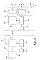
- the vehicle is not described in any more detail than is necessary to explain the invention and typically includes an engine shown at 16 which is controlled by the driver in respect of initiating its operation and changing performance functions, optionally in conjunction with an electronic engine management unit (EMU) 20.
- EMU electronic engine management unit
- the engine 16 is powered by liquid fuel delivered to the engine from a storage tank 22 by way of a fuel delivery system including electrically operated supply pump 23 and fuel distribution and input means 24, which may comprise a carburettor (as shown ghosted at 24 1 ) that includes a small storage chamber for fuel, or, more conventionally in modem gasoline engines and in compression ignition (diesel) engines, a plurality of fuel injection pumps and valves 24 2 .
- a fuel delivery system including electrically operated supply pump 23 and fuel distribution and input means 24, which may comprise a carburettor (as shown ghosted at 24 1 ) that includes a small storage chamber for fuel, or, more conventionally in modem gasoline engines and in compression ignition (diesel) engines, a plurality of fuel injection pumps and valves 24 2 .
- Other features of the vehicle, as they relate to its operation are shown by the enlargement of the circled region, in Figure 1(b) .
- Such operator effects operation by initiating functioning of both the vehicle chassis and of the engine by which the vehicle moves. Initiation of operation usually is effected by inserting a key device 26 1 into a co-operable lock 26 2 which releases a steering lock (not shown) and authorises the EMU 20 to enable the engine to be started and the supply pump 23 to deliver fuel for the engine.
- the key device 26 1 may take the form of a physical key 27 1 paired with a lock 28 1 fitted to the vehicle and optionally carry in the key radio frequency transducing means 27 2 , paired with transceiver 28 2 in the vehicle.
- the transceiving means is arranged to program the key in use, issuing it with a code to be transmitted upon next usage so that only if the codes agree does the key function to initiate operation of the engine, and for practical purposes making it virtually impossible to start the engine without permission of the genuine or authorised key.
- An alternative key device employs a key-card of flexible plastics material and carrying thereon authorising means, in the form of a magnetic strip or a semiconductor integrated circuit including a processor and memory and often known to as a smart-card, which is able to co-operate with a reader 29 2 fitted to the vehicle.
- a card-key is able to store a larger number of parameters vital to initiating operation of the engine, and may also be re-programmed from usage-to-usage, but nevertheless serves as a key device to effect initiation of vehicle engine operation by virtue of being in the possession of the user at start-up and in position in the vehicle thereafter.
- such in-situ programming of the primary engine initiating device is intended to make it difficult for an unauthorised user to tamper with the vehicle, particularly the EMU in order to start the engine and steal the vehicle, or as additional anti-theft devices which respond to an attempt at unauthorised entry into the vehicle cab or engine bay or even disturbance of the vehicle itself to trigger an alarm.
- an authorisation system indicated generally at 30, with the intention of permitting functioning of the vehicle normally under driver control only in the actual presence of an authorised user, rather than merely the presence of the normal key devices which hitherto has constituted de-facto authorisation.
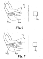
- an authorised user may be any occupant 12 i of the vehicle cab, conveniently, but not necessarily, the driver 12, and presence is that defined by presence within or immediately adjacent the vehicle cab.
- the authorisation system comprises wireless communication means 32 having complementary parts 34 and 36 arranged to be carried in operation by the apparatus (the vehicle) and a said authorised user of the apparatus (here shown as driver 12) respectively.
- the parts may communicate by any suitable contactless system, such as optically or ultrasonically, but preferably operate at radio frequencies and preferably at those in the GHz or microwave bands.
- the parts of the communication means are arranged to effect, within the spatial envelope of the cab that defmes a permissible working relationship between the authorised user and apparatus (vehicle), a communication link defined by continual transfer of identifying information pairing the authorised user and the apparatus.
- the identifying information is described further below as is the nature of continual transfer, being with respect to a temporal envelope which supplements the spatial envelope defining permissible separation of the parts.
- the communication means 32 is responsive to the existence of said link that confirms the "presence" of the authorised user to effect authorisation of the vehicle, permitting it to function normally under control of a driver-operator in possession of the appropriate key device, but to deny authorisation when not present, preventing a driver who is not the authorised user from using the key device obtaining or maintaining functioning of the engine of the vehicle.
- Initiation of operation of the vehicle may be effected separately from, or contingent upon, such communication link, but most importantly, the communication means is responsive to cessation of an existing communication link with previously authorised said functioning apparatus to inhibit the normal functioning of the apparatus after a delaying interval that is characteristic of the authorised user and vehicle as having moved apart.
- the delaying interval is a time delay of duration in excess of 0.5 minutes and may typically be of the order of 5 minutes, although other time delays, may be set according to anticipated or actual conditions pertaining.
- This embodiment is particularly concerned with, and adapted for, an above-discussed hijack situation wherein the fully functioning vehicle, containing the authorised user and driver, is halted and the occupant or occupants forced to leave, and possibly compounded by the hijacker then removing from the concernedwhile occupants any cellular telephone or comparable communication devices by which the authorities may be alerted before driving away in the otherwise functioning vehicle.
- the user part 36 of the communication means 32 is arranged to be worn inconspicuously or secreted about the person of the authorised user, and notwithstanding the requirement for such part to effect a radio communication link with the apparatus part, this is feasible having regard to the relatively small spatial envelope in which a communication link has to be established with the apparatus part.
- the apparatus part 34 may be permanently fixed with respect to the vehicle to control its engine operation or fixed with respect to, or form part of, an operating key device, such as key 27 1 or key card 29 1 , which is, in operation, carried by the vehicle and without which device it will not function.
- an operating key device such as key 27 1 or key card 29 1 , which is, in operation, carried by the vehicle and without which device it will not function.
- the authorised user carrying the user part of the communication means, upon entering the spatial envelope defined substantially by the vehicle cab creates the circumstances whereby the communication means may form a communication link between the user-part and apparatus part, which link is considered maintained by the continual transfer of identifying information pairing the authorised user and vehicle to the apparatus part.
- the communication means may exist because of permanent or prior empowerment of the relevant part or parts, or may result from empowerment arising from the driver using the appropriate key device to initiate functioning of the engine. Notwithstanding various options discussed below, by combination of a function-authorising wireless communication link and key device - enabled operation of the vehicle engine, the vehicle is set to function normally without any additional overt actions necessary on the part of the authorised user, other than his presence.
- the communication link between apparatus and user parts and initiating operational functioning of the vehicle may be combined or kept totally separate.
- the apparatus and/or user parts may begin to transmit upon disarming of an anti-theft device that permits the authorised user to enter the cab. Subsequent initiation of engine operation is contingent upon establishment of the communication link.
- the apparatus part may be caused to function when operation of the vehicle ignition is initiated by the normal key devices but before the engine starts, the completion of operating engine function being contingent upon the establishment of a communication link during the procedure.
- an alternative method is to permit the engine to function by the normal key devices but with the apparatus part arranged to initiate inhibition if a communication link is not established within a relatively short time delay that is insufficient for the driver to move the vehicle to a place of danger before functioning ceases.
- the user part may be connectable physically with the vehicle and/or the apparatus part in order to interchange stored values of identifying codes and establish the communication link and/or to permit initiation of engine function which is maintained after the user part is removed and returned to the person of the authorised user to be carried thereabout.
- the apparatus part 34 of the communication means is functionally connected to the vehicle, to cause the vehicle to stop functioning after a time delay of such duration as to permit the hijacker to become separated from the authorised user.
- the time delay as used in this embodiment not only permits the hijacker to move the vehicle from the hijack scene for a distance that is intended to be too great to justify returning to confront the authorised user but also an opportunity for the authorised user to leave the hijack scene.
- the vehicle is stopped from functioning at the appropriate time either by affecting the operation of one or more components of the vehicle that causes the vehicle (engine or chassis) to stop suddenly or by modifying operation of one or more components so that functionality is removed from the vehicle more gradually over at least part of the delay interval.
- the engine may also be caused to stop functioning by effecting temporary, intermittent inhibition of multiple functional aspects of the vehicle to disguise from the hijacker responsibility of any particular functional aspect for non-functioning of the vehicle, and thus thwarting by-passing of the control for that functional aspect.
- the communication means may be arranged to respond to a resumed presence of the user part to re-establish the communication link that returns full functionality to the vehicle, but preferably the apparatus part is arranged to lock the inhibition of vehicle functionality at least until some positive action is taken to remove the inhibition.
- a vehicle would have its functionality locked out on a temporary basis, to be overcome by locally or remotely controlled re-setting switch means, but other apparatus, depending largely upon the structural form of the apparatus part, may have its functionality locked on a temporary or permanent basis.
- locking out of vehicle functionality may comprise permanently destroying information or functioning of the card.
- a programmable key device that locks-out upon cessation of the communication link may be re-programmed to overcome temporary loss of functionality.
- the apparatus part of the communication means may also include authorised disablement means to override the authorisation system when the vehicle is in the care of trusted non-authorised users, conveniently associated with such re-setting means or as a replacement "master key" device.
- FIG. 2 shows in schematic, block diagram form a first embodiment of communication means at 32 1 that comprises apparatus and user parts 34 1 and 36 1 respectively and control means 38 1 coupled to the engine functioning components 20 and/or 23.
- the user part 36 1 includes user transmission means 40 1 which is operable to emit radio frequency radiation at low power in any suitable band, a power supply unit (PSU) 44 1 comprising a self-contained primary or secondary battery and, if necessary, a manually operated power switch 45 1 to prevent drainage of the battery when the transmission means is not in use, and user processing means 46 1 including timing and storage means 47 1 to produce an identity reference unique to the user part and apparatus part pair for transmission and effect transmission of radiation modulated in accordance with the identity reference.
- PSU power supply unit
- user processing means 46 1 including timing and storage means 47 1 to produce an identity reference unique to the user part and apparatus part pair for transmission and effect transmission of radiation modulated in accordance with the identity reference.
- modulation as used herein is intended to include any common form of effecting variation of a radio frequency emission and is intent to include modulation in amplitude or frequency or emission per se in accordance with a digital code.
- the user processing means 46 1 is arranged to effect transmissions at intervals, each transmission having a duration short relative to the interval.
- the apparatus part 34 1 comprises apparatus reception means 50 1 which is operable to receive also demodulate or decode the emissions from the user transmission means, power supply unit 54 1 , which is a secondary battery arranged to be charged by connection to the vehicle supply but operable independently thereof, and apparatus processing means 56 1 (having timing and storage means 57 1 ) arranged to synchronise the apparatus reception means with respect to receiving the transmissions from the user transmission means and for recognising the identity reference from the appropriate modulation form.
- the modulating form is a digital code produced by the user processing means and retrieved by the apparatus processing means.
- the apparatus processing means stores a corresponding code or the means for generating such code whereby a comparison is able to confirm or otherwise the transfer of identifying information including said identity reference, and by such transfer the existence of a communication link between them.
- the transmitting power or directionality of the user transmission means and/or the receiving sensitivity or directionality of the apparatus reception means combine to define the spatial envelope upon which a successful communication link is based.
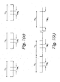
- such temporal envelope comprises in each of a plurality of sequential time intervals, herein called communication intervals TI 1 , TI 2 ... TI N , .. a time window TW 1 , TW 2 .... TW N , ... of predetermined duration.
- Both user processing means 46 1 and apparatus processing means 56 1 define the communication intervals and the user processing means effects transmission for or within a time window in each communication interval.
- the apparatus processing means determines if in each communication interval a suitably modulated transmission is received. If desired, the apparatus processing means may be further restricted to acknowledge receipt of a transmission only if it occurs within a time window predefined as occurring within a part of the window.
- each received (and confirmed) transmission may be used to synchronise the apparatus processing means with respect to the user processing means and/or the transmitted identity reference may contain data defining the relative time to, and duration of, the next transmission.
- the communication intervals may be contiguous as shown in Figure 3(b) and, if desired, the time windows in each may extend from the full interval, as shown for time window TW N , creating a continuous transmission-reception situation, although such a scheme may be perceived to be wasteful of user part power reserves.
- the above described communication means 32 1 with its apparatus and user parts 34 1 and 36 1 has simplicity in having a single transmitter and receiver, but also some limitation, such as the need to determine in advance what the user transmission means is to transmit and when and for the apparatus reception means to be set in advance, or adapt to received transmissions, to pair therewith. Also, insofar as it is intended for the user part 36 1 to be carried unobtrusively by the authorised user, the self-contained power supply 44 1 is necessarily of limited capacity and notwithstanding only intermittent transmissions may require the user to effect manual switching of the part for use.
- FIG. 4 this shows for a second embodiment of authorisation system communication means 32 2 comprising apparatus part 342 and user part 36 2 .
- the apparatus part 34 2 includes in association with the apparatus processing means 56 2 apparatus transmission means 60 2 and the user part 36 2 includes in association with the user processing means 46 2 user reception means 70 2 .
- the communications between the parts from the apparatus part to the user part may permit several enhancements in terms of the identification information pairing them, the temporal envelope and, importantly, notwithstanding the additional components, minimising the power usage and requirements of the user part.
- Transmissions from the apparatus part to the user part may contain the aforementioned identity reference, so that the user processing means only responds thereto, but preferably contains also a further identity reference which is decoded by the user processing means 46 2 such that the user transmission means in turn transmits its next signal modulated in accordance with them both.
- both the user processing means and the apparatus processing means have access to two identity references.
- the identity references may be made to change constantly, as a rolling code, and notwithstanding the need for frequent transmissions to sustain the communication link.
- the transmission of signals from the apparatus part to the user part also permits the latter to be arranged only to transmit when in receipt of a suitable signal from the apparatus transmission means.
- the apparatus processing means may define the aforementioned time intervals and time windows in accordance with some pre-programmed and/or randomised regime whereby the transmission of signals from the user transmission means is always synchronised to a reception window.
- the radio frequency energy of apparatus part transmissions may be employed by the user part 36 2 to provide or supplement the operating power of its supply 44 2 ; that is, the user reception means may include rectification means 72 2 for a part of the signal and charge a secondary battery source or, in some instances, a capacitor (not shown) that replaces such primary or secondary battery source.
- the receipt or lack of receipt of signals from the apparatus transmission means may comprise direct control over the user part's ability to effect a response transmission.
- the user processing means 46 2 may put the user part into a low consumption "sleep" mode until awoken by receipt of a suitably verified transmission from the apparatus part.
- the bi-directional arrangement may comprise the functional equivalent of the above-described uni-directional communication link in which the user part is autonomous in sending an appropriate authorisation signal to the apparatus part but relies upon a signal of indeterminate form from the apparatus part to derive operating power.
- the identity reference modulation applied to transmissions from each of the apparatus transmission means and user transmission means comprises a digital code which is based upon one or more random or pseudo-random numbers generated within either or both of the apparatus part or user part and/or encrypted and decrypted in accordance with algorithms stored in said parts; for example, in a manner similar to that described in the aforementioned GB-A-2342742 but here applied to the radio frequency transmissions between the parts and repeated continually as defined by the temporal envelope.
- the apparatus part expects to receive a signal which contains an identifying reference unique to the pair, and preferably one unique to the transmission, insofar as it is based upon a number randomly or pseudo-randomly generated by the apparatus part transmitted to and modified by the user processing means for its identity reference from which the original number that can be extracted for confirmation.
- the transmission and reception parts may also be arranged during each transmission to undergo carrier frequency hopping to further lessen the chance of incorrect pairing or loss of communication link in accordance with the Bluetooth standard or a comparable radio frequency peer-to-peer networking standard.
- 36 1 including apparatus transmission means and apparatus reception means when initially empowered by initiation of operation of the vehicle engine, transmits its availability and the user part, with the user reception means and user transmission means, responds when within range to register with the apparatus part and establish a basic communication link.
- Registration by the apparatus part that it has established a communication link with a suitably complementary user part may be sufficient, but as such a standard for pairing items is intended to effect communication between hitherto unknown devices, preferably such link is considered established only upon transfer also of additional and unique pair identifying information.
- the apparatus part expects receipt of an appropriate piece of identifying information within each time window and such receipt within each time window to provide authorisation of the apparatus until the next window. If that information is not forthcoming, because the paired user part is not within range, as defined by the spatial envelope manifested by incorrect modulation information or insufficient received signal strength, the apparatus part, through the control means 38 1 initiates a check for the absence of receipt of identifying information in a predetermined number of consecutive time windows to determine if it was a temporary loss or permanent. If such check confirms absence for said predetermined number of consecutive time windows, a cessation of communication link is declared to exist and delayed loss of vehicle function initiated.
- FIG. 5 a third embodiment of communication means 32 3 is shown which effects a communication link between apparatus part 34 3 and user part 36 3 based upon bi-directional communication.
- the user part is in principle the same as 34 2 but, in keeping with the aim of achieving or an unobtrusive, readily carried form empowered by radio frequency energy transmitted by the apparatus transmission means, or indeed any other suitable electromagnetic energy, comprises an analog or digital identity reference 'tag' recognised by a reader in the form of the apparatus transmission means/apparatus reception means that transmits to it continually (as herein defined) and responds as appropriate to receipt or lack of receipt of a response.
- Such a tag may take a simple analog form, as an inductive-capacitive (L-C) circuit tuned to a particular frequency of apparatus transmission means transmission and which effects reflection or frequency doubling of the apparatus transmission means transmission, or in a digital form in which a stored code is transmitted upon empowerment by reception of radio frequency energy from apparatus transmission means.
- L-C inductive-capacitive
- Such digital tags are available from Microchip Technology Inc, for example as RFID model MCRF202, or Temic semiconductors as model U9280M-H.
- any apparatus part it may be arranged to be paired with a plurality of different user parts and likewise for any user part to be paired with a plurality of different apparatus parts, and although it would be expected for the apparatus part to pair with a single user part to define a communication link by cycling through possible user parts to pair with upon initiation, the setting up of a communication link based upon intermittent transmission-reception windows makes it possible to accommodate several authorised user parts for one apparatus part simultaneously.
- the system may employ other than time delay alone to effect delayed inhibition of normal functioning of the apparatus.
- a vehicle or other apparatus may measure distance and the distance measured following cessation of the communication link may be compared with a stored, predetermined value or with a value computed from the speed attained and a delay time.
- such means may be provided by the apparatus or communication means carrying acceleration responsive means that responds to continuous or periodic acceleration forces and computes therefrom a distance travelled. This may be in response to cessation of communication link and for comparison with a predetermined or otherwise computed distance that denotes the end of the delaying interval.
- the acceleration responsive means may comprise, a linear accelerometer.
- the acceleration responsive means may comprise a pedometer sensor of the type that is carried by an individual and responds to the acceleration pattern of ambulating, that is, walking and/or running, coupled with user stride length, to determine how much ground has been covered by the individual walking and/or running.
- the pedometer function is advertised as a feature of the protected apparatus that is normally carried by the user and incorporated into it to effect, in addition to its normal function, that of a pedometer informing the user of ambulatory behaviour, including also means to calibrate it according to the stride/pattern of the authorised user and providing information on demand.
- the device may be arranged to respond to cessation of a communication link between the apparatus and authorised user to adopt a "standard" stride pattern and monitor thereby achievement of a separation distance.
- such determination of speed and distance may be employed to calculate a delaying interval time before inhibiting functionality.
- both time and distance may be employed as parameters, for example, inhibition may be effected only after a time delay of, say, at least 0.5 min and a distance travelled of at least 0.8 Km (0.5 mile), the actual values being a matter of choice and dependant upon the apparatus involved..
- the apparatus may be a vehicle to which a speed limit is enforced for different categories of authorised user, with possibly a minimum speed limit for an unauthorised user, or a computer to which certain programs are available to different categories of authorised user.
- the authorisation system may effect control of the engine, by way of electrical ignition or fuel supply, to set a maximum speed that the vehicle cannot exceed, such speed being low relative to that normally experienced by other road users so as both to limit the rate of departure and make the vehicle more noticeable to other road users and the authorities, without risking it becoming stranded in a dangerous place.
- the apparatus part may be arranged such that the speed limitation is a predetermined default setting that is overridden by the communication link with the authorised user to provide said normal operation not inhibited in this way, that is, it may take a fixed value, for example 25 Km/h (15 mph) that most drivers exceed where practicable.
- traffic flow may occasionally be at a lesser speed.
- the vehicle may monitor the maximum or average speed within a time frame to compute a running average before and/or preferably after cessation of the communication link in order to derive a truer speed profile or function that is normal for the road conditions prevailing for the thief, so that after the delaying interval the speed is set to a fraction of the norm.
- an analogous operating speed limit may be imposed to render the apparatus traceable whilst of little economic value to the taker.
- the authorisation system may impose a variety of functional inhibitions on the apparatus at the end of the delaying interval it may also function to effect different degrees of inhibition to authorised users having different levels of authority.
- the user part of the communication means may be programmable or be constructed to different forms to permit different levels or categories of authorisation of specific apparatus.
- the user part comprises a plurality of discrete modules each of which is carried by an authorised user to have effect.
- FIG. 6 shows in block a schematic form at 30 4 a fourth embodiment of authorisation system in accordance with the invention wherein the communication means 32 4 comprises, in addition to the user and apparatus parts 36 4 and 34 4 , corresponding to parts 36 2 and 34 2 described above.
- the user part 36 4 comprises a master module 36 4M that performs the authorisation of apparatus normal functioning as described above.
- The, or each, supplementary module is associated with a specific feature of the apparatus not critical to its normal function and is operable to effect a communication link with the master module in any of the ways described above for communication between user part and apparatus part, the communication means as a whole being responsive to absence of a communication link between a said supplementary module and master module to inhibit function of the associated feature within the functioning apparatus.
- the user part 36 5 comprises a master module 36 5M and at least one supplementary module 36 5S1 etc. having associated therewith a specific supplementary functional feature of the functioning apparatus not critical to its normal functioning.
- at least one supplementary module is operable to effect a supplementary communication link with the apparatus part rather than the master module and the communication means as a whole is responsive to absence of a communication link between a said supplementary module and the apparatus part to inhibit operation of the associated supplementary functional feature.
- All of the above described embodiments comprises establishment of a communication link between a user part and apparatus parts of a pair directly to effect normal functioning of the apparatus.
- the user part has minimum dimensions and thus has minimal on-board power storage capacity and low transmission power, insofar as the apparatus part is in general associated with a vehicle (or other apparatus) which is large enough to permit the apparatus part to accommodate within it, or be connected to, a power source of significant storage capacity. It is preferred to design the apparatus part for maximum sensitivity to reception of signals from low power user part transmissions and to maximise the apparatus transmission means power (if appropriate) to lessen any power burden on the user part.
- Figure 8 shows in block a schematic form at 30 6 a sixth embodiment of authorisation system in accordance with the invention wherein the communication means 32 6 comprises, in addition to the user and apparatus parts 36 6 and 34 6 , corresponding to parts 36 2 and 34 2 described above, a relay part 80 6 arranged to be disposed, in respect of the communication link, between the parts wherein at least the user part 36 6 , and preferably also the apparatus part 34 6 , is arranged to transfer identifying information by way of the relay part in preference to establishing a communication link directly.
- the relay part is arranged to be carried by the authorised user 12 in operation and may be less unobtrusive than the user part 36 6 and including a more powerful a battery power supply and transmission means and, if appropriate, receiver means, for communicating over a distance with respect to the apparatus part that is long relative to the distance to the user part, thereby permitting the user part to be made even smaller and carried more unobtrusively.
- the relay part is under the physical control of the authorised user and may advantageously comprise additional functioning apparatus, such as a cellular phone device, which inherently includes many of the components required of the relay part, and from which the user also runs the risk of being separated, not only when forcibly separated form the vehicle by a hijacker but also when the apparatus is carried by the user remotely from the vehicle.
- additional functioning apparatus such as a cellular phone device
- the communication link is thus effected by transmission from the user part to the relay part and from the relay part to the apparatus part, so that if, having established such link by virtue of the relay-carrying authorised user correctly initiating functioning of the apparatus, any cessation of the link caused by either or both of the user and relay parts being separated from the apparatus part or each other causes delayed inhibition of vehicle functioning.
- the relay part may be present in respect of transmissions from the user part to apparatus part, insofar as any link is bi-directional and carries identifying information unique to the transmission, it is preferred that the relay part encompasses full bi-directional communications with at least the user part, and many cellular phones are already enabled to communicate with local devices using the above-mentioned Bluetooth technology.
- the communication means may be arranged such that notwithstanding the presence of a relay part, any communication link between user and apparatus parts is not contingent upon the presence of such relay part; that is, if the relay part is present and functioning then it is employed in establishing the communication link but if it is not present and functioning the apparatus and user parts nevertheless attempt to communicate directly. It will be appreciated that if appropriate the relay part may form part of the transmission path from the user part and apparatus part and for the apparatus part, with fewer power constraints, transmit directly with the user part.
- a functioning cellular phone or the like which is normally carried on the person of the authorised user when away from the vehicle, may be disposed in the vicinity of, rather than on the person of, the authorised user when the latter is within the vehicle but may nevertheless be employed as such relay part without affecting functionality of both cellular phone and vehicle.
- relay part may comprise a so-called hand-held or lap-top computer, watch or entertainment device, any of which may be carried by, and at risk of being taken from, an authorised user. Any such device is particularly suitable if, as mentioned above, it is enabled for wireless peer-to-peer networking using the Bluetooth or like system.
- Such relay part may, of course, have no other function than to operate as a relay part.
- the duration of the delay is chosen to permit the authorised user to become distanced from a robber of such apparatus.
- initiation of the delay may cause telephonically enabled apparatus to call a prescribed number with a prescribed message (possibly to the authorities or network administrator to cancel the subscription) and the inhibition of function may comprise permanent removal of functionality, such as destruction of a cellular phone network SIM card.
- the apparatus part may be sensibly arranged to abort delayed inhibition in response to re-establishment of communication link, so that this is transparent to the authorised user, or alternatively, require the authorised user to perform some partial or complete re-authorisation as a deterrent to leaving the apparatus functioning.
- apparatus other than an automobile as described above may be configured to work with master and supplementary modules that enable a suitably authorised user, in possession of the relevant module or modules, to access functions not otherwise accessible beyond the basic functionality given by the master module.
Claims (25)
- Autorisierungssystem in Ergänzung zu Schlüsselmitteln zur Ermöglichung einer Funktionskontrolle einer Vorrichtung (10) nur in Anwesenheit eines autorisierten Benutzers (12), umfassend Ergänzungsteile (34, 36) von Funkkommunikationsmitteln (32), welche Teile (34, 36) dazu angeordnet sind, von der Vorrichtung (10) und vom autorisierten Benutzer (12) getragen zu werden und dazu nutzbar sind, eine Kommunikationsverbindung innerhalb einer Raumhülle herzustellen, die eine vorher festgelegte, zulässige Arbeitsbeziehung zwischen den Ergänzungsteiten definiert, dadurch gekennzeichnet, dass die Kommunikationsverbindung durch einen kontinuierlichen Transfer unter Bezugnahme auf eine Zeithülle von Identifizierungsinformationen definiert wird, die in Entsprechung zu einem rollenden Digitalcode moduliert werden, der für jede Übertragung geändert wird und der auf mindestens einer zufälligen oder pseudozufälligen Zahl basiert, die im Vorrichtungsteil (34) und/oder im Benutzerteil (36) generiert und/oder in Entsprechung zu in diesen Teilen gespeicherten Algorithmen verschlüsselt und entschlüsselt wird, wobei die Zeithülle ein Zeitfenster einer vorher festgelegten Dauer in jedem einer Mehrzahl von aufeinanderfolgenden Zeitintervallen zur Paaranordnung der Ergänzungsteile umfasst, wobei das Kommunikationsmittel eine operative Kontrolle der Vorrichtung (10) bei Bestand der Kommunikationsverbindung ausführt und wobei die Kommunikationsverbindung beendet werden kann, wenn die Ergänzungsteile (34, 36) von der Raumhülle getrennt werden, wobei der von der Vorrichtung getragene Ergänzungsteil (34) Mittel zur Hemmung der normalen Funktion der Vorrichtung nach einem Verzögerungszeitintervall bei Beendigung der Kommunikationsverbindung umfasst, wobei das Verzögerungsintervall ein durch beschleunigungsempfindliches Mittel und/oder ein Pedometermittel gemessen wird, die repräsentativ für eine vorher festgelegte Distanz sind, die zwischen dem autorisierten Benutzer (12) und der Vorrichtung (10) zurückgelegt worden ist.
- Autorisierungssystem gemäß Anspruch 1, geeignet zur Verwendung mit beweglichen Vorrichtungen, die dazu geeignet sind, aus dem Besitz des autorisierten Benutzers während der Funktionsausübung übernommen zu werden, wobei die Vorrichtung oder das Kommunikationsmittel Mittel zum Messen der zurückgelegten Distanz umfassen und das Kommunikationsmittel dazu verwendet werden kann, das Verzögerungsintervall als Funktion der von der Vorrichtung zurückgelegten Distanz zur Anwendung zu bringen.
- Autorisierungssystem gemäß Anspruch 2, in dem das Mittel zum Messen der Distanz ein beschteunigungsempfindliches Mittel umfasst, das von der Vorrichtung oder dem Kommunikationsmittel, das auf die Bewegung der Vorrichtung oder des Kommunikationsmittels reagiert, getragen wird, um eine Bestimmung der von der Vorrichtung zurückgelegten Distanz wenigstens während des Verzögerungsintervalls auszuführen.
- Autorisierungssystem gemäß Anspruch 1, in dem das Pedometermittel ein Kalibriermittel umfasst, das zur Kalibrierung des Pedometers gemäß dem Schrittmuster des autorisierten Benutzers angeordnet ist, und wobei die Vorrichtung ein Mittel umfasst, das dazu dient, dem autorisierten Benutzer auf Verlangen die von der Vorrichtung, die vom autorisierten Benutzer während der normalen Funktionsausführung der Vorrichtung getragen wurde, zurückgelegte Distanz bereitzustellen.
- Autorisierungssystem gemäß Anspruch 1, in dem die Vorrichtung oder das Kommunikationsmittel ein Zeitgebermittel umfasst und das Kommunikationsmittel dazu verwendet werden kann, das Verzögerungsintervall als Zeitverzögerung zur Anwendung zu bringen.
- Aütorisierungssystem gemäß einem der vorangehenden Ansprüche, dazu angepasst, die Nutzung von Vorrichtungen, die ein Fahrzeug mit einer Insassenkabine und einem Motor umfassen, und die normale Funktion des Motors durch einen Betreiber zu ermöglichen, der ein Insasse und Fahrer ist, dadurch gekennzeichnet, dass die Raumhülle dadurch begrenzt ist, dass sie im wesentlichen koexistierend mit der Insassenkabine ist, und dass der Vorrichtungsteil dazu angeordnet ist, eine Kommunikationsverbindung mit einem Benutzerteil zu bilden, der von einem Insassen der Kabine getragen wird, und operativ mit dem Fahrzeug gekoppelt zu werden, um das Funktionieren des Fahrzeugmotors durch den Fahrer zu autorisieren oder zu hemmen.
- Autorisierungssystem gemäß einem der vorangehenden Ansprüche, dazu angepasst, die Nutzung von Vorrichtungen, die ein Fahrzeug umfassen, zu ermöglichen, dadurch gekennzeichnet, dass die Vorrichtung oder das Kommunikationsmittel dazu angeordnet ist, operativ mit dem Fahrzeug gekoppelt zu werden, um das Fahrzeug dazu zu autorisieren, mit jeder vom Fahrer gewünschten Geschwindigkeit zu fahren oder das Fahrzeug zu hemmen, schneller als eine vom System am Ende des Verzögerungsintervalls festgelegte Geschwindigkeit zu fahren.
- Autorisierungssystem gemäß Anspruch 7, in dem die Vorrichtung oder der Kommunikationsmittelteil ein Mittel zur Ableitung einer Geschwindigkeitsfunktion umfasst, die auf jede Geschwindigkeit bezogen ist, die während des Verzögerungsintervalls erreicht wurde, und um am Ende des Verzögerungsintervalls das Fahrzeug am Überschreiten einer Geschwindigkeit zu hindern, die ein Bruchteil jeder durch die Geschwindigkeitsfunktion dargestellten Geschwindigkeit ist.
- Autorisierungssystem gemäß einem der vorangehenden Ansprüche, ausgeführt für die Zulassung der Nutzung von Vorrichtungen, die ein Fahrzeug umfassen, dessen Motor über ein Kraftstoffzuführungssystem mit Kraftstoff versorgt wird und wobei der Vorrichtungsteil des Systems dazu angeordnet ist, operativ mit dem Fahrzeug gekoppelt zu werden, um die Zuführung von Kraftstoff zum Motor zu autorisieren oder zu hemmen und diese Hemmung der normalen Funktionsweise nach einem Verzögerungsintervall durch fortschreitende Reduzierung der Zuführung von Kraftstoff zum Motor während des Intervalls zu bewirken.
- Autorisierungssystem gemäß einem der vorangehenden Ansprüche, in dem der Vorrichturigsteil dazu verwendet werden kann, im Verzögerungsintervall eine vorübergehende oder permanente Hemmung mehrerer Funktionsaspekte der Vorrichtung während des Verzögerungsintervalls zu bewirken, um die Verantwortung eines bestimmten Funktionsaspekts für das Nichtfunktionieren der Vorrichtung zu verbergen.
- Autorisierungssystem gemäß einem der vorangehenden Ansprüche, ausgeführt für die Verwerdung mit Vorrichtungen, in denen der Betrieb der Vorrichtung durch den Betreiber vor der Durchführung einer Kontrolle der Funktionsweise derselben ausgelöst wird, dadurch gekennzeichnet, dass der Vorrichtungsteil auf die Auslösung des Betriebs der Vorrichtung durch den Betreiber reagiert, um die Einrichtung des Kommunikationsverbindung vor der oder gleichzeitig mit der Funktionsausführung der Vorrichtung auszulösen.
- Autorisierungssystem gemäß einem der vorangehenden Ansprüche, in dem das Kommunikationsmittel ein vom Benutzerteil getragenes Benutzerübertragungsmittel und ein vom Vorrichtungsteil getragenes Vorrichtungsempfangsmittel umfasst, worin ein Mittel zur Herstellung einer für das Paar einzigartigen Identitätsreferenz enthalten ist, wobei das Benutzerübertragungsmittel dazu verwendbar ist, Strahlung zu übertragen, die in Entsprechung zu der Identitätsreferenz moduliert wurde, und wobei das Vorrichtungsempfangsmittel auf den Empfang der modulierten Strahlung reagiert, um durch die Übertragung von Identifizierungsinformationen einschließlich der ldentitätsreferenz die Existenz einer Kommunikationsverbindung zwischen ihnen zu bestätigen.
- Autorisierungssystem gemäß Anspruch 12, in dem das Kommunikationsmittel ferner Vorrichtungsübertragüngsmittel im Vorrichtungsteil und Benutzerempfangsmittel im Benutzerteil umfasst, die dazu angeordnet sind, bidirektionale Kommunikationen zwischen dem Vorrichtungsteil und dem Benutzerteil zu bewirken, und wobei der Benutzerteil und der Vorrichtungsteil jeweils ein Mittel zur Herstellung einer weiteren für das Paar einzigartigen .. Identitätsreferenz besitzen, wobei das Vorrichtungsübertragungsmittel dazu verwendbar ist, Strahlung zu übertragen, die in Entsprechung zu der zusätzlichen Identitätsreferenz moduliert wurde, und das Benutzerempfangsmittel auf den Empfang der modulierten Strahlung reagiert, um die Existenz einer Kommunikationsverbindung zwischen ihnen zu bestätigen.
- Autorisierungssystem gemäß einem der Ansprüche 11 bis 13, in dem die Modulation der übertragenen Strahlung in Entsprechung zu einem Digitalcode ist und in dem das Kommunikationsmittel dazu angeordnet ist, wenigstens die Trägerfrequenz der modulierten Strahlung in Entsprechung zu einem Digitalcode während der Kommunikation zu ändern.
- Autorisierungssystem gemäß Anspruch 14, in dem das Kommunikationsmittel dazu angeordnet ist, eine Kommunikationsverbindung in Entsprechung zur Bluetooth-Funkspezifikation herzustellen.
- Autorisierungssystem gemäß einem der vorangehenden Ansprüche, in dem der Vorrichtungsteil auf die Abwesenheit des Empfangs von Identifizierungsinformationen in einer festgelegten Anzahl aufeinanderfolgender Zeitfenster reagiert, um die Beendigung der Kommunikationsverbindung zu bestimmen.
- Autorisierungssystem gemäß Anspruch 16, in dem die aufeinanderfolgenden Kommunikationsintervalle aneinanderhängend oder beabstandet sind.
- Autorisierungssystem gemäß einem der vorangehenden Ansprüche, in dem das Kommunikationsmittel einen Relais-Teil umfasst, der dazu angeordnet ist, in Bezug auf die Kommunikationsverbindung zwischen dem Benutzerteil und dem Vorrichtungsteil eingefügt zu werden, und wobei wenigstens der Benutzerteil dazu angeordnet ist, identifizierungsinformationen über den Relais-Teil bevorzugt gegenüber der Einrichtung einer direkten Kommunikationsverbindung mit dem Vorrichtungsteil zu übertragen.
- Autorisierungssystem gemäß Anspruch 18, in dem das Kommunikationsmittel dazu angeordnet ist, die Herstellung einer Kommunikationsverbindung einschließlich des Relais-Teils zu versuchen, und in Abwesenheit eines solchen zu versuchen, eine Kommunikationsverbindung direkt zwischen dem Benutzerteil und dem Vorrichtungsteil herzustellen.
- Autorisierungssystem gemäß Anspruch 18 oder Anspruch 19, in dem der Relais-Teil dazu angeordnet ist, im Betrieb vom Benutzer getragen zu werden.
- Autorisierungssystem gemäß einem der Ansprüche 18 bis 20, in dem der Relais-Teil zusätzliche funktionelle Vorrichtungen unter der Kontrolle des autorisierten Benutzers umfasst und der Relais-Teil dazu angeordnet ist, in Reaktion auf die Beendigung einer bestehenden Kommunikationsverbindung mit dem Benutzerteil des Kommunikationsmittels während der Funktionsausführung der zusätzlichen Vorrichtung eine Hemmung der normalen Funktionsausführung nach einem Verzögerungsintervall zu bewirken.
- Autorisierungssystem gemäß einem der vorangehenden Ansprüche, in dem der Benutzerteil eine Mehrzahl physisch diskreter Module umfasst, bestehend aus einem Mastermodul, das dazu verwendet werden kann, eine Kommunikationsverbindung mit dem Vorrichtungsteil herzustellen, und aus wenigstens einem Ergänzungsmodul, das dazu verwendet werden kann, eine Kommunikationsverbindung mit dem Mastermodul herzustellen, wobei jedem Ergänzungsmodul ein spezifisches Funktionsmerkmal der Funktionsvorrichtung zugeordnet ist und das Kommunikationsmittel auf die Abwesenheit einer Kommunikationsverbindung zwischen einem Ergänzungsmodul und einem Mastermodul reagiert, um die Funktion des Merkmals in der Funktionsvorrichtung zu hemmen.
- Autorisierungssystem gemäß einem der vorangehenden Ansprüche, in dem der Benutzerteil eine Mehrzahl physisch diskreter Module umfasst, bestehend aus einem Mastermodul, das dazu verwendet werden kann, eine Kommunikationsverbindung mit dem Vorrichtungsteil herzustellen, und aus wenigstens einem Ergänzungsmodul, das dazu verwendet werden kann, eine ergänzende Kommunikationsverbindung mit dem Vorrichtungsteil herzustellen, wobei jedem Ergänzungsmodul ein spezifisches ergänzendes Funktionsmerkmal der Funktionsvorrichtung zugeordnet ist, das für dessen normale Funktion nicht kritisch ist, und wobei das Kommunikationsmittel auf die Abwesenheit einer Kommunikationsverbindung zwischen einem Ergänzungsmodul und dem Vorrichtungsteil reagiert, um den Betrieb des zugeordneten ergänzenden Funktionsmerkmals zu hemmen.
- Autorisierungssystem gemäß einem der vorangehenden Ansprüche, in dem der Vorrichtungsteil des Kommunikationsmittels dazu angeordnet ist, von der Vorrichtung in der Funktionsausführung abnehmbar getragen zu werden und ein Vorrichtungsbetriebsauslösungsmittel umfasst, das dazu verwendet werden kann, den Anfangsbetrieb der Vorrichtung zu ermöglichen.
- Autorisierungssystem gemäß einem der vorangehenden Ansprüche für Vorrichtungen mit Telefonkommunikationsfähigkeit, in dem der Vorrichtungsteil während des Verzögerungsintervalls verwendet werden kann, um einen Telefonanruf an einen vorher festgelegten Empfänger durchzuführen.
Applications Claiming Priority (5)
| Application Number | Priority Date | Filing Date | Title |
|---|---|---|---|
| IE20030219 | 2003-03-25 | ||
| IE20030219 | 2003-03-25 | ||
| GB0322314A GB2399924A (en) | 2003-03-25 | 2003-09-24 | Security authorisation system requires wireless communication link between complentary parts |
| GB0322314 | 2003-09-24 | ||
| PCT/GB2004/001274 WO2004085213A1 (en) | 2003-03-25 | 2004-03-24 | Security authorisation system |
Publications (2)
| Publication Number | Publication Date |
|---|---|
| EP1606149A1 EP1606149A1 (de) | 2005-12-21 |
| EP1606149B1 true EP1606149B1 (de) | 2014-05-07 |
Family
ID=33099996
Family Applications (1)
| Application Number | Title | Priority Date | Filing Date |
|---|---|---|---|
| EP04722899.4A Expired - Lifetime EP1606149B1 (de) | 2003-03-25 | 2004-03-24 | Sicherheitsberechtigungssystem |
Country Status (4)
| Country | Link |
|---|---|
| US (1) | US8749345B2 (de) |
| EP (1) | EP1606149B1 (de) |
| JP (1) | JP2006523572A (de) |
| WO (1) | WO2004085213A1 (de) |
Cited By (26)
| Publication number | Priority date | Publication date | Assignee | Title |
|---|---|---|---|---|
| US9809155B2 (en) | 2015-10-27 | 2017-11-07 | Steering Solutions Ip Holding Corporation | Retractable steering column assembly having lever, vehicle having retractable steering column assembly, and method |
| US9828016B2 (en) | 2015-06-24 | 2017-11-28 | Steering Solutions Ip Holding Corporation | Retractable steering column system, vehicle having the same, and method |
| US9840271B2 (en) | 2015-06-29 | 2017-12-12 | Steering Solutions Ip Holding Corporation | Retractable steering column with rake limiter |
| US9845106B2 (en) | 2015-08-31 | 2017-12-19 | Steering Solutions Ip Holding Corporation | Overload protection for belt drive mechanism |
| US9849904B2 (en) | 2015-07-31 | 2017-12-26 | Steering Solutions Ip Holding Corporation | Retractable steering column with dual actuators |
| US9862403B1 (en) | 2016-11-29 | 2018-01-09 | Steering Solutions Ip Holding Corporation | Manually retractable steering column assembly for autonomous vehicle |
| US9919724B2 (en) | 2015-05-29 | 2018-03-20 | Steering Solutions Ip Holding Corporation | Retractable steering column with manual retrieval |
| US10029676B2 (en) | 2014-01-29 | 2018-07-24 | Steering Solutions Ip Holding Corporation | Hands on steering wheel detect |
| US10029725B2 (en) | 2015-12-03 | 2018-07-24 | Steering Solutions Ip Holding Corporation | Torque feedback system for a steer-by-wire vehicle, vehicle having steering column, and method of providing feedback in vehicle |
| US10112639B2 (en) | 2015-06-26 | 2018-10-30 | Steering Solutions Ip Holding Corporation | Vehicle steering arrangement and method of making same |
| US10160472B2 (en) | 2015-10-20 | 2018-12-25 | Steering Solutions Ip Holding Corporation | Steering column with stationary hub |
| US10160473B2 (en) | 2016-09-13 | 2018-12-25 | Steering Solutions Ip Holding Corporation | Steering column decoupling system |
| US10160477B2 (en) | 2016-08-01 | 2018-12-25 | Steering Solutions Ip Holding Corporation | Electric power steering column assembly |
| US10189496B2 (en) | 2016-08-22 | 2019-01-29 | Steering Solutions Ip Holding Corporation | Steering assembly having a telescope drive lock assembly |
| US10239552B2 (en) | 2016-10-14 | 2019-03-26 | Steering Solutions Ip Holding Corporation | Rotation control assembly for a steering column |
| US10310605B2 (en) | 2016-11-15 | 2019-06-04 | Steering Solutions Ip Holding Corporation | Haptic feedback for steering system controls |
| US10481602B2 (en) | 2016-10-17 | 2019-11-19 | Steering Solutions Ip Holding Corporation | Sensor fusion for autonomous driving transition control |
| US10496102B2 (en) | 2016-04-11 | 2019-12-03 | Steering Solutions Ip Holding Corporation | Steering system for autonomous vehicle |
| US10562561B2 (en) | 2016-04-25 | 2020-02-18 | Steering Solutions Ip Holding Corporation | Electrical power steering control using system state predictions |
| US10577009B2 (en) | 2015-06-16 | 2020-03-03 | Steering Solutions Ip Holding Corporation | Retractable steering column assembly and method |
| US10589774B2 (en) | 2015-05-01 | 2020-03-17 | Steering Solutions Ip Holding Corporation | Counter rotation steering wheel |
| US10766518B2 (en) | 2015-06-25 | 2020-09-08 | Steering Solutions Ip Holding Corporation | Rotation control system for a steering wheel and method |
| US10780915B2 (en) | 2016-12-07 | 2020-09-22 | Steering Solutions Ip Holding Corporation | Vehicle steering system having a user experience based automated driving to manual driving transition system and method |
| US10875566B2 (en) | 2018-03-22 | 2020-12-29 | Steering Solutions Ip Holding Corporation | Stow release assembly for a manually adjustable steering column assembly |
| US10974756B2 (en) | 2018-07-31 | 2021-04-13 | Steering Solutions Ip Holding Corporation | Clutch device latching system and method |
| US11560169B2 (en) | 2015-06-11 | 2023-01-24 | Steering Solutions Ip Holding Corporation | Retractable steering column system and method |
Families Citing this family (46)
| Publication number | Priority date | Publication date | Assignee | Title |
|---|---|---|---|---|
| US20070205876A1 (en) * | 2004-11-16 | 2007-09-06 | Hap Nguyen | RFID-based systems and methods for preventing hi-jacker from using airplanes as guided missiles, vessels as guided torpedoes, and automotive or rail conveyances as bombs |
| US7394352B2 (en) * | 2005-04-11 | 2008-07-01 | International Truck Intellectual Property Company, Llc | Vehicle control network integrated theft deterrent system |
| FR2884787A1 (fr) * | 2005-04-22 | 2006-10-27 | Thomas Dominique Leandr Buriez | Systeme antivol semi-passif avec verrouillage automatique du dispositif identifiant en cas de perte d'oubli ou de vol |
| GB2426616A (en) * | 2005-05-25 | 2006-11-29 | Giga Byte Tech Co Ltd | Wireless authentication and log-in |
| FI20065390L (fi) | 2006-06-08 | 2007-12-09 | Innohome Oy | Automaattinen elektroniikka- ja sähkölaitteiden monitasoisen käyttöoikeuden ohjausjärjestelmä |
| US7757803B2 (en) * | 2006-07-14 | 2010-07-20 | Richard Fiske | Motor vehicle operator identification and maximum speed limiter |
| US8082122B2 (en) * | 2006-12-12 | 2011-12-20 | Samsung Electronics Co., Ltd. | Mobile device having a motion detector |
| US9715665B2 (en) | 2009-09-21 | 2017-07-25 | Ford Global Technologies, Llc | Methods and systems for monitoring the condition of vehicle components from a nomadic wireless device or computer |
| US8346432B2 (en) * | 2009-09-23 | 2013-01-01 | Ford Global Technologies, Llc | System and method for remotely controlling vehicle components from a nomadic communication device or computer |
| US20110071725A1 (en) * | 2009-09-23 | 2011-03-24 | Ford Global Technologies, Llc | Remotely interacting with a vehicle to perform servicing and engineering functions from a nomadic device or computer |
| US8558690B2 (en) * | 2009-10-01 | 2013-10-15 | Ford Global Technologies, Llc | Vehicle system passive notification using remote device |
| US8558678B2 (en) * | 2010-02-25 | 2013-10-15 | Ford Global Technologies, Llc | Method and systems for detecting an unauthorized use of a vehicle by an authorized driver |
| US8525657B2 (en) * | 2010-02-25 | 2013-09-03 | Ford Global Technologies, Llc | Methods and systems for determining a tire pressure status |
| US20110215899A1 (en) * | 2010-03-08 | 2011-09-08 | Ford Global Technologies, Llc | Method and system for authorizing a vehicle driveaway |
| US8614622B2 (en) | 2010-03-08 | 2013-12-24 | Ford Global Technologies, Llc | Method and system for enabling an authorized vehicle driveaway |
| US10075806B2 (en) * | 2010-03-19 | 2018-09-11 | Ford Global Technologies, Llc | Wireless vehicle tracking |
| US8474569B2 (en) * | 2011-04-26 | 2013-07-02 | Continental Automotive Systems, Inc. | System and method for self-detecting vehicle theft |
| US8954006B2 (en) * | 2011-06-15 | 2015-02-10 | GM Global Technology Operations LLC | Computer to vehicle wireless link |
| US9166958B2 (en) | 2012-07-17 | 2015-10-20 | Texas Instruments Incorporated | ID-based control unit-key fob pairing |
| US9448547B2 (en) * | 2013-04-16 | 2016-09-20 | Brian S. Messenger | Sensor and power coordinator for vehicles and production lines that hosts removable computing and messaging devices |
| CN103318136A (zh) * | 2013-07-05 | 2013-09-25 | 无锡商业职业技术学院 | 一种汽车防盗装置 |
| US10099700B2 (en) | 2014-04-30 | 2018-10-16 | Ford Global Technologies, Llc | Method and system for driver tailored interaction time alert |
| US9672723B2 (en) | 2014-09-03 | 2017-06-06 | Vuzitech Llc | Security system for a motorized cycle |
| US10351159B2 (en) | 2015-05-01 | 2019-07-16 | Steering Solutions Ip Holding Corporation | Retractable steering column with a radially projecting attachment |
| US10343706B2 (en) | 2015-06-11 | 2019-07-09 | Steering Solutions Ip Holding Corporation | Retractable steering column system, vehicle having the same, and method |
| DE102016110791A1 (de) | 2015-06-15 | 2016-12-15 | Steering Solutions Ip Holding Corporation | Gestensteuerung für ein einfahrbares Lenkrad |
| DE102016111473A1 (de) | 2015-06-25 | 2016-12-29 | Steering Solutions Ip Holding Corporation | Stationäre lenkradbaugruppe und verfahren |
| US9845097B2 (en) | 2015-08-12 | 2017-12-19 | Ford Global Technologies, Llc | Driver attention evaluation |
| CN105869423B (zh) * | 2015-11-12 | 2018-08-07 | 乐卡汽车智能科技(北京)有限公司 | 基于卫星定位的预警方法及系统、服务器 |
| DE102016203715A1 (de) * | 2016-03-08 | 2017-09-14 | Deere & Company | Anordnung zur Kontrolle von Funktionen einer Arbeitsmaschine |
| US10351161B2 (en) | 2016-05-27 | 2019-07-16 | Steering Solutions Ip Holding Corporation | Steering column with manual retraction |
| CN107521547B (zh) | 2016-06-21 | 2020-03-10 | 操纵技术Ip控股公司 | 转向柱组件的自锁伸缩式致动器 |
| US10457313B2 (en) | 2016-06-28 | 2019-10-29 | Steering Solutions Ip Holding Corporation | ADAS wheel locking device |
| US10363958B2 (en) | 2016-07-26 | 2019-07-30 | Steering Solutions Ip Holding Corporation | Electric power steering mode determination and transitioning |
| US10384708B2 (en) | 2016-09-12 | 2019-08-20 | Steering Solutions Ip Holding Corporation | Intermediate shaft assembly for steer-by-wire steering system |
| US10399591B2 (en) | 2016-10-03 | 2019-09-03 | Steering Solutions Ip Holding Corporation | Steering compensation with grip sensing |
| US10421475B2 (en) | 2016-11-15 | 2019-09-24 | Steering Solutions Ip Holding Corporation | Electric actuator mechanism for retractable steering column assembly with manual override |
| US10351160B2 (en) | 2016-11-30 | 2019-07-16 | Steering Solutions Ip Holding Corporation | Steering column assembly having a sensor assembly |
| US20180334031A1 (en) * | 2016-12-14 | 2018-11-22 | Julia Matthews | Ignition interlock device |
| US10370022B2 (en) | 2017-02-13 | 2019-08-06 | Steering Solutions Ip Holding Corporation | Steering column assembly for autonomous vehicle |
| US10385930B2 (en) | 2017-02-21 | 2019-08-20 | Steering Solutions Ip Holding Corporation | Ball coupling assembly for steering column assembly |
| US10449927B2 (en) | 2017-04-13 | 2019-10-22 | Steering Solutions Ip Holding Corporation | Steering system having anti-theft capabilities |
| CN107609861A (zh) * | 2017-09-26 | 2018-01-19 | 北京中车重工机械有限公司 | 一种工程设备及其授时锁车方法和装置 |
| US20190047578A1 (en) * | 2018-09-28 | 2019-02-14 | Intel Corporation | Methods and apparatus for detecting emergency events based on vehicle occupant behavior data |
| US11820324B2 (en) | 2021-02-24 | 2023-11-21 | William D. Yates | Vehicle equipped with safety system and method of responding to an unauthorized possession of a vehicle |
| US11727733B2 (en) * | 2021-05-11 | 2023-08-15 | Ford Global Technologies, Llc | Enabling operator controls for machine operation |
Family Cites Families (24)
| Publication number | Priority date | Publication date | Assignee | Title |
|---|---|---|---|---|
| US5444430A (en) * | 1993-01-04 | 1995-08-22 | Mcshane; Richard | Motor vehicle security system |
| US5604384A (en) * | 1993-02-08 | 1997-02-18 | Winner International Royalty Corporation | Anti-theft device for motor vehicle |
| US5557254A (en) * | 1993-11-16 | 1996-09-17 | Mobile Security Communications, Inc. | Programmable vehicle monitoring and security system having multiple access verification devices |
| AUPM402394A0 (en) * | 1994-02-23 | 1994-03-17 | Monaad Corporation Pty Limited | Security access arrangement |
| US5494130A (en) | 1994-11-02 | 1996-02-27 | Foster; Peter J. | Anti-theft and anti-hijacking system for motor vehicles |
| US6771168B1 (en) * | 1995-04-24 | 2004-08-03 | Hap Nguyen | Automotive system to prevent carjacking |
| DE19546171C1 (de) * | 1995-12-11 | 1996-11-28 | Siemens Ag | Diebstahlschutzsystem für ein Kraftfahrzeug |
| US5804810A (en) * | 1996-06-26 | 1998-09-08 | Par Government Systems Corporation | Communicating with electronic tags |
| FR2768676B1 (fr) * | 1997-09-22 | 1999-11-19 | Valeo Securite Habitacle | Antivol pour un vehicule automobile comportant des identifiants secondaires |
| US6611789B1 (en) * | 1997-10-02 | 2003-08-26 | Personal Electric Devices, Inc. | Monitoring activity of a user in locomotion on foot |
| US6525645B2 (en) * | 1998-08-26 | 2003-02-25 | Lear Corporation | Integrated remote keyless entry and garage door opener using a universal repeater |
| US6175608B1 (en) * | 1998-10-28 | 2001-01-16 | Knowmo Llc | Pedometer |
| JP2000145224A (ja) * | 1998-11-12 | 2000-05-26 | Mazda Motor Corp | キーレスエントリシステム |
| JP2000145225A (ja) * | 1998-11-12 | 2000-05-26 | Mazda Motor Corp | キーレスエントリシステム |
| FR2800782B1 (fr) * | 1999-11-10 | 2001-12-21 | Valeo Securite Habitacle | Vehicule automobile equipe d'un systeme d'acces et/ou de demarrage dit "mains libres" |
| JP2001237626A (ja) | 2000-02-21 | 2001-08-31 | Omron Corp | 制御装置 |
| GB0005010D0 (en) * | 2000-03-01 | 2000-04-19 | Spinnaker Int Ltd | Electronic pedometer expected behaviour detector and security system incorporating such a detector |
| EP1239420A1 (de) * | 2001-03-05 | 2002-09-11 | Siemens Aktiengesellschaft | Identifikationssystem und Codegeber zum Nachweis einer Berechtigung für den Zugang zu einem Objekt oder die Benutzung eines Objekts, insbesondere eines Kraftfahrzeugs |
| FR2821809A1 (fr) * | 2001-03-09 | 2002-09-13 | Bressane De Travaux Electr Bte | Systeme d'alarme pour vehicule automobile |
| DE10152830A1 (de) * | 2001-10-25 | 2003-05-08 | Philips Corp Intellectual Pty | Sicherungssystem für tragbare elektrische Geräte |
| DE10159604A1 (de) * | 2001-12-05 | 2003-06-12 | Atmel Germany Gmbh | Verfahren zur Erkennung einer Weiterleitung bei einer kontaktlosen Datenübertragung |
| US6937138B2 (en) * | 2002-03-25 | 2005-08-30 | Craig T. Underdahl | Keyless remote door locking system |
| US6718240B1 (en) * | 2002-08-28 | 2004-04-06 | Honda Giken Kogyo Kabushiki Kaisha | Remote keyless entry system |
| US6700488B1 (en) * | 2002-09-05 | 2004-03-02 | Se-Kure Controls, Inc. | Security system for a portable device |
-
2004
- 2004-03-24 JP JP2006506014A patent/JP2006523572A/ja active Pending
- 2004-03-24 US US10/550,821 patent/US8749345B2/en not_active Expired - Fee Related
- 2004-03-24 WO PCT/GB2004/001274 patent/WO2004085213A1/en active Application Filing
- 2004-03-24 EP EP04722899.4A patent/EP1606149B1/de not_active Expired - Lifetime
Cited By (26)
| Publication number | Priority date | Publication date | Assignee | Title |
|---|---|---|---|---|
| US10029676B2 (en) | 2014-01-29 | 2018-07-24 | Steering Solutions Ip Holding Corporation | Hands on steering wheel detect |
| US10589774B2 (en) | 2015-05-01 | 2020-03-17 | Steering Solutions Ip Holding Corporation | Counter rotation steering wheel |
| US9919724B2 (en) | 2015-05-29 | 2018-03-20 | Steering Solutions Ip Holding Corporation | Retractable steering column with manual retrieval |
| US11560169B2 (en) | 2015-06-11 | 2023-01-24 | Steering Solutions Ip Holding Corporation | Retractable steering column system and method |
| US10577009B2 (en) | 2015-06-16 | 2020-03-03 | Steering Solutions Ip Holding Corporation | Retractable steering column assembly and method |
| US9828016B2 (en) | 2015-06-24 | 2017-11-28 | Steering Solutions Ip Holding Corporation | Retractable steering column system, vehicle having the same, and method |
| US10766518B2 (en) | 2015-06-25 | 2020-09-08 | Steering Solutions Ip Holding Corporation | Rotation control system for a steering wheel and method |
| US10112639B2 (en) | 2015-06-26 | 2018-10-30 | Steering Solutions Ip Holding Corporation | Vehicle steering arrangement and method of making same |
| US9840271B2 (en) | 2015-06-29 | 2017-12-12 | Steering Solutions Ip Holding Corporation | Retractable steering column with rake limiter |
| US9849904B2 (en) | 2015-07-31 | 2017-12-26 | Steering Solutions Ip Holding Corporation | Retractable steering column with dual actuators |
| US9845106B2 (en) | 2015-08-31 | 2017-12-19 | Steering Solutions Ip Holding Corporation | Overload protection for belt drive mechanism |
| US10160472B2 (en) | 2015-10-20 | 2018-12-25 | Steering Solutions Ip Holding Corporation | Steering column with stationary hub |
| US9809155B2 (en) | 2015-10-27 | 2017-11-07 | Steering Solutions Ip Holding Corporation | Retractable steering column assembly having lever, vehicle having retractable steering column assembly, and method |
| US10029725B2 (en) | 2015-12-03 | 2018-07-24 | Steering Solutions Ip Holding Corporation | Torque feedback system for a steer-by-wire vehicle, vehicle having steering column, and method of providing feedback in vehicle |
| US10496102B2 (en) | 2016-04-11 | 2019-12-03 | Steering Solutions Ip Holding Corporation | Steering system for autonomous vehicle |
| US10562561B2 (en) | 2016-04-25 | 2020-02-18 | Steering Solutions Ip Holding Corporation | Electrical power steering control using system state predictions |
| US10160477B2 (en) | 2016-08-01 | 2018-12-25 | Steering Solutions Ip Holding Corporation | Electric power steering column assembly |
| US10189496B2 (en) | 2016-08-22 | 2019-01-29 | Steering Solutions Ip Holding Corporation | Steering assembly having a telescope drive lock assembly |
| US10160473B2 (en) | 2016-09-13 | 2018-12-25 | Steering Solutions Ip Holding Corporation | Steering column decoupling system |
| US10239552B2 (en) | 2016-10-14 | 2019-03-26 | Steering Solutions Ip Holding Corporation | Rotation control assembly for a steering column |
| US10481602B2 (en) | 2016-10-17 | 2019-11-19 | Steering Solutions Ip Holding Corporation | Sensor fusion for autonomous driving transition control |
| US10310605B2 (en) | 2016-11-15 | 2019-06-04 | Steering Solutions Ip Holding Corporation | Haptic feedback for steering system controls |
| US9862403B1 (en) | 2016-11-29 | 2018-01-09 | Steering Solutions Ip Holding Corporation | Manually retractable steering column assembly for autonomous vehicle |
| US10780915B2 (en) | 2016-12-07 | 2020-09-22 | Steering Solutions Ip Holding Corporation | Vehicle steering system having a user experience based automated driving to manual driving transition system and method |
| US10875566B2 (en) | 2018-03-22 | 2020-12-29 | Steering Solutions Ip Holding Corporation | Stow release assembly for a manually adjustable steering column assembly |
| US10974756B2 (en) | 2018-07-31 | 2021-04-13 | Steering Solutions Ip Holding Corporation | Clutch device latching system and method |
Also Published As
| Publication number | Publication date |
|---|---|
| US20060273885A1 (en) | 2006-12-07 |
| US8749345B2 (en) | 2014-06-10 |
| JP2006523572A (ja) | 2006-10-19 |
| EP1606149A1 (de) | 2005-12-21 |
| WO2004085213A1 (en) | 2004-10-07 |
Similar Documents
| Publication | Publication Date | Title |
|---|---|---|
| EP1606149B1 (de) | Sicherheitsberechtigungssystem | |
| JP5908588B2 (ja) | セキュリティシステムおよびそのデバイス | |
| EP1717117B1 (de) | Fahrzeugdiebstahlsicherung und -system | |
| JP4802888B2 (ja) | 車載装置用盗難抑止システム | |
| US8264320B2 (en) | Aftermarket keyless starter | |
| US6411217B1 (en) | Vehicle disabling system | |
| CA3008872A1 (en) | Auto security and auto safety system | |
| CN108068759B (zh) | 防止中继攻击的系统和方法 | |
| EP1041227B1 (de) | Mit einer Warnvorrichtung ausgerüstetes handfreies Zugangssystem für ein Kraftfahrzeug | |
| CN105745384A (zh) | 车载无线通信装置 | |
| US7358849B1 (en) | Vehicle anti-theft system | |
| JP3721145B2 (ja) | 車載機器遠隔制御システム | |
| GB2399924A (en) | Security authorisation system requires wireless communication link between complentary parts | |
| JP2003252176A (ja) | 車両用盗難防止システム | |
| JP2003525366A (ja) | 受動式光学識別システム | |
| JP2016074377A (ja) | 車両用盗難防止装置 | |
| JP4264193B2 (ja) | 車載機器遠隔制御装置 | |
| EP2073179B1 (de) | Diebstahlschutzsystem und Verfahren zum Aktivieren einer Betriebsart einer elektronischen Vorrichtung | |
| JP2004324227A (ja) | 遠隔操作用の携帯機 | |
| JP6248826B2 (ja) | 車両用無線通信システム、車載機、及び、携帯機 | |
| JP4256176B2 (ja) | 電子キーシステムの作動制御装置 | |
| JP2008273520A (ja) | エンジン始動制御システム | |
| JP4306446B2 (ja) | 車両盗難防止システム | |
| JP6625913B2 (ja) | 車両制御装置 | |
| CN105292057A (zh) | 一种指纹识别汽车防盗系统 |
Legal Events
| Date | Code | Title | Description |
|---|---|---|---|
| PUAI | Public reference made under article 153(3) epc to a published international application that has entered the european phase |
Free format text: ORIGINAL CODE: 0009012 |
|
| 17P | Request for examination filed |
Effective date: 20050921 |
|
| AK | Designated contracting states |
Kind code of ref document: A1 Designated state(s): AT BE BG CH CY CZ DE DK EE ES FI FR GB GR HU IE IT LI LU MC NL PL PT RO SE SI SK TR |
|
| AX | Request for extension of the european patent |
Extension state: AL LT LV MK |
|
| DAX | Request for extension of the european patent (deleted) | ||
| 17Q | First examination report despatched |
Effective date: 20080208 |
|
| GRAP | Despatch of communication of intention to grant a patent |
Free format text: ORIGINAL CODE: EPIDOSNIGR1 |
|
| INTG | Intention to grant announced |
Effective date: 20131030 |
|
| GRAS | Grant fee paid |
Free format text: ORIGINAL CODE: EPIDOSNIGR3 |
|
| GRAA | (expected) grant |
Free format text: ORIGINAL CODE: 0009210 |
|
| AK | Designated contracting states |
Kind code of ref document: B1 Designated state(s): AT BE BG CH CY CZ DE DK EE ES FI FR GB GR HU IE IT LI LU MC NL PL PT RO SE SI SK TR |
|
| REG | Reference to a national code |
Ref country code: GB Ref legal event code: FG4D |
|
| REG | Reference to a national code |
Ref country code: AT Ref legal event code: REF Ref document number: 666380 Country of ref document: AT Kind code of ref document: T Effective date: 20140515 |
|
| REG | Reference to a national code |
Ref country code: IE Ref legal event code: FG4D |
|
| REG | Reference to a national code |
Ref country code: DE Ref legal event code: R096 Ref document number: 602004045031 Country of ref document: DE Effective date: 20140618 |
|
| REG | Reference to a national code |
Ref country code: DK Ref legal event code: T3 Effective date: 20140808 |
|
| REG | Reference to a national code |
Ref country code: CH Ref legal event code: NV Representative=s name: SPIERENBURG AND PARTNER AG, PATENT- UND MARKEN, CH |
|
| REG | Reference to a national code |
Ref country code: SE Ref legal event code: TRGR |
|
| REG | Reference to a national code |
Ref country code: NL Ref legal event code: T3 |
|
| REG | Reference to a national code |
Ref country code: AT Ref legal event code: MK05 Ref document number: 666380 Country of ref document: AT Kind code of ref document: T Effective date: 20140507 |
|
| PG25 | Lapsed in a contracting state [announced via postgrant information from national office to epo] |
Ref country code: FI Free format text: LAPSE BECAUSE OF FAILURE TO SUBMIT A TRANSLATION OF THE DESCRIPTION OR TO PAY THE FEE WITHIN THE PRESCRIBED TIME-LIMIT Effective date: 20140507 Ref country code: CY Free format text: LAPSE BECAUSE OF FAILURE TO SUBMIT A TRANSLATION OF THE DESCRIPTION OR TO PAY THE FEE WITHIN THE PRESCRIBED TIME-LIMIT Effective date: 20140507 Ref country code: GR Free format text: LAPSE BECAUSE OF FAILURE TO SUBMIT A TRANSLATION OF THE DESCRIPTION OR TO PAY THE FEE WITHIN THE PRESCRIBED TIME-LIMIT Effective date: 20140808 |
|
| PG25 | Lapsed in a contracting state [announced via postgrant information from national office to epo] |
Ref country code: AT Free format text: LAPSE BECAUSE OF FAILURE TO SUBMIT A TRANSLATION OF THE DESCRIPTION OR TO PAY THE FEE WITHIN THE PRESCRIBED TIME-LIMIT Effective date: 20140507 Ref country code: ES Free format text: LAPSE BECAUSE OF FAILURE TO SUBMIT A TRANSLATION OF THE DESCRIPTION OR TO PAY THE FEE WITHIN THE PRESCRIBED TIME-LIMIT Effective date: 20140507 Ref country code: PL Free format text: LAPSE BECAUSE OF FAILURE TO SUBMIT A TRANSLATION OF THE DESCRIPTION OR TO PAY THE FEE WITHIN THE PRESCRIBED TIME-LIMIT Effective date: 20140507 |
|
| PG25 | Lapsed in a contracting state [announced via postgrant information from national office to epo] |
Ref country code: PT Free format text: LAPSE BECAUSE OF FAILURE TO SUBMIT A TRANSLATION OF THE DESCRIPTION OR TO PAY THE FEE WITHIN THE PRESCRIBED TIME-LIMIT Effective date: 20140908 |
|
| PG25 | Lapsed in a contracting state [announced via postgrant information from national office to epo] |
Ref country code: BE Free format text: LAPSE BECAUSE OF FAILURE TO SUBMIT A TRANSLATION OF THE DESCRIPTION OR TO PAY THE FEE WITHIN THE PRESCRIBED TIME-LIMIT Effective date: 20140507 Ref country code: SK Free format text: LAPSE BECAUSE OF FAILURE TO SUBMIT A TRANSLATION OF THE DESCRIPTION OR TO PAY THE FEE WITHIN THE PRESCRIBED TIME-LIMIT Effective date: 20140507 Ref country code: RO Free format text: LAPSE BECAUSE OF FAILURE TO SUBMIT A TRANSLATION OF THE DESCRIPTION OR TO PAY THE FEE WITHIN THE PRESCRIBED TIME-LIMIT Effective date: 20140507 Ref country code: EE Free format text: LAPSE BECAUSE OF FAILURE TO SUBMIT A TRANSLATION OF THE DESCRIPTION OR TO PAY THE FEE WITHIN THE PRESCRIBED TIME-LIMIT Effective date: 20140507 Ref country code: CZ Free format text: LAPSE BECAUSE OF FAILURE TO SUBMIT A TRANSLATION OF THE DESCRIPTION OR TO PAY THE FEE WITHIN THE PRESCRIBED TIME-LIMIT Effective date: 20140507 |
|
| REG | Reference to a national code |
Ref country code: DE Ref legal event code: R097 Ref document number: 602004045031 Country of ref document: DE |
|
| PLBE | No opposition filed within time limit |
Free format text: ORIGINAL CODE: 0009261 |
|
| STAA | Information on the status of an ep patent application or granted ep patent |
Free format text: STATUS: NO OPPOSITION FILED WITHIN TIME LIMIT |
|
| 26N | No opposition filed |
Effective date: 20150210 |
|
| REG | Reference to a national code |
Ref country code: DE Ref legal event code: R097 Ref document number: 602004045031 Country of ref document: DE Effective date: 20150210 |
|
| PG25 | Lapsed in a contracting state [announced via postgrant information from national office to epo] |
Ref country code: SI Free format text: LAPSE BECAUSE OF FAILURE TO SUBMIT A TRANSLATION OF THE DESCRIPTION OR TO PAY THE FEE WITHIN THE PRESCRIBED TIME-LIMIT Effective date: 20140507 |
|
| PG25 | Lapsed in a contracting state [announced via postgrant information from national office to epo] |
Ref country code: LU Free format text: LAPSE BECAUSE OF FAILURE TO SUBMIT A TRANSLATION OF THE DESCRIPTION OR TO PAY THE FEE WITHIN THE PRESCRIBED TIME-LIMIT Effective date: 20150324 Ref country code: MC Free format text: LAPSE BECAUSE OF FAILURE TO SUBMIT A TRANSLATION OF THE DESCRIPTION OR TO PAY THE FEE WITHIN THE PRESCRIBED TIME-LIMIT Effective date: 20140507 |
|
| REG | Reference to a national code |
Ref country code: FR Ref legal event code: PLFP Year of fee payment: 13 |
|
| PGFP | Annual fee paid to national office [announced via postgrant information from national office to epo] |
Ref country code: IE Payment date: 20160929 Year of fee payment: 13 Ref country code: DK Payment date: 20160930 Year of fee payment: 13 Ref country code: GB Payment date: 20160929 Year of fee payment: 13 Ref country code: NL Payment date: 20160930 Year of fee payment: 13 |
|
| PGFP | Annual fee paid to national office [announced via postgrant information from national office to epo] |
Ref country code: FR Payment date: 20160929 Year of fee payment: 13 Ref country code: SE Payment date: 20160930 Year of fee payment: 13 |
|
| PGFP | Annual fee paid to national office [announced via postgrant information from national office to epo] |
Ref country code: CH Payment date: 20160930 Year of fee payment: 13 Ref country code: DE Payment date: 20160930 Year of fee payment: 13 |
|
| PGFP | Annual fee paid to national office [announced via postgrant information from national office to epo] |
Ref country code: IT Payment date: 20160930 Year of fee payment: 13 |
|
| PG25 | Lapsed in a contracting state [announced via postgrant information from national office to epo] |
Ref country code: HU Free format text: LAPSE BECAUSE OF FAILURE TO SUBMIT A TRANSLATION OF THE DESCRIPTION OR TO PAY THE FEE WITHIN THE PRESCRIBED TIME-LIMIT; INVALID AB INITIO Effective date: 20040324 Ref country code: BG Free format text: LAPSE BECAUSE OF FAILURE TO SUBMIT A TRANSLATION OF THE DESCRIPTION OR TO PAY THE FEE WITHIN THE PRESCRIBED TIME-LIMIT Effective date: 20140507 |
|
| PG25 | Lapsed in a contracting state [announced via postgrant information from national office to epo] |
Ref country code: TR Free format text: LAPSE BECAUSE OF FAILURE TO SUBMIT A TRANSLATION OF THE DESCRIPTION OR TO PAY THE FEE WITHIN THE PRESCRIBED TIME-LIMIT Effective date: 20140507 |
|
| REG | Reference to a national code |
Ref country code: DE Ref legal event code: R119 Ref document number: 602004045031 Country of ref document: DE |
|
| REG | Reference to a national code |
Ref country code: DK Ref legal event code: EBP Effective date: 20170331 |
|
| REG | Reference to a national code |
Ref country code: SE Ref legal event code: EUG Ref country code: CH Ref legal event code: PL |
|
| REG | Reference to a national code |
Ref country code: NL Ref legal event code: MM Effective date: 20170401 |
|
| GBPC | Gb: european patent ceased through non-payment of renewal fee |
Effective date: 20170324 |
|
| PG25 | Lapsed in a contracting state [announced via postgrant information from national office to epo] |
Ref country code: SE Free format text: LAPSE BECAUSE OF NON-PAYMENT OF DUE FEES Effective date: 20170325 |
|
| REG | Reference to a national code |
Ref country code: IE Ref legal event code: MM4A |
|
| REG | Reference to a national code |
Ref country code: FR Ref legal event code: ST Effective date: 20171130 |
|
| PG25 | Lapsed in a contracting state [announced via postgrant information from national office to epo] |
Ref country code: DE Free format text: LAPSE BECAUSE OF NON-PAYMENT OF DUE FEES Effective date: 20171003 Ref country code: FR Free format text: LAPSE BECAUSE OF NON-PAYMENT OF DUE FEES Effective date: 20170331 Ref country code: NL Free format text: LAPSE BECAUSE OF NON-PAYMENT OF DUE FEES Effective date: 20170401 |
|
| PG25 | Lapsed in a contracting state [announced via postgrant information from national office to epo] |
Ref country code: GB Free format text: LAPSE BECAUSE OF NON-PAYMENT OF DUE FEES Effective date: 20170324 Ref country code: IT Free format text: LAPSE BECAUSE OF NON-PAYMENT OF DUE FEES Effective date: 20170324 Ref country code: LI Free format text: LAPSE BECAUSE OF NON-PAYMENT OF DUE FEES Effective date: 20170331 Ref country code: CH Free format text: LAPSE BECAUSE OF NON-PAYMENT OF DUE FEES Effective date: 20170331 Ref country code: IE Free format text: LAPSE BECAUSE OF NON-PAYMENT OF DUE FEES Effective date: 20170324 |
|
| PG25 | Lapsed in a contracting state [announced via postgrant information from national office to epo] |
Ref country code: DK Free format text: LAPSE BECAUSE OF NON-PAYMENT OF DUE FEES Effective date: 20170331 |