EP1602844B1 - Wälzlagereinheit - Google Patents
Wälzlagereinheit Download PDFInfo
- Publication number
- EP1602844B1 EP1602844B1 EP04720208A EP04720208A EP1602844B1 EP 1602844 B1 EP1602844 B1 EP 1602844B1 EP 04720208 A EP04720208 A EP 04720208A EP 04720208 A EP04720208 A EP 04720208A EP 1602844 B1 EP1602844 B1 EP 1602844B1
- Authority
- EP
- European Patent Office
- Prior art keywords
- cylindrical portion
- peripheral surface
- cover
- outer ring
- fitting direction
- Prior art date
- Legal status (The legal status is an assumption and is not a legal conclusion. Google has not performed a legal analysis and makes no representation as to the accuracy of the status listed.)
- Expired - Lifetime
Links
- 238000005096 rolling process Methods 0.000 title claims abstract description 31
- 230000002093 peripheral effect Effects 0.000 claims abstract description 65
- 239000002184 metal Substances 0.000 claims abstract description 10
- 239000011347 resin Substances 0.000 claims description 13
- 229920005989 resin Polymers 0.000 claims description 13
- 239000000463 material Substances 0.000 claims description 7
- 230000004323 axial length Effects 0.000 claims description 6
- 238000005452 bending Methods 0.000 description 6
- 238000001514 detection method Methods 0.000 description 4
- 230000035939 shock Effects 0.000 description 3
- 239000000725 suspension Substances 0.000 description 3
- XLYOFNOQVPJJNP-UHFFFAOYSA-N water Substances O XLYOFNOQVPJJNP-UHFFFAOYSA-N 0.000 description 3
- 239000004952 Polyamide Substances 0.000 description 2
- 239000004734 Polyphenylene sulfide Substances 0.000 description 2
- 238000001816 cooling Methods 0.000 description 2
- 238000010438 heat treatment Methods 0.000 description 2
- 229920002647 polyamide Polymers 0.000 description 2
- 229920001707 polybutylene terephthalate Polymers 0.000 description 2
- 229920000069 polyphenylene sulfide Polymers 0.000 description 2
- 229910000677 High-carbon steel Inorganic materials 0.000 description 1
- 229910000831 Steel Inorganic materials 0.000 description 1
- 230000006978 adaptation Effects 0.000 description 1
- 239000010960 cold rolled steel Substances 0.000 description 1
- 238000005336 cracking Methods 0.000 description 1
- 230000000593 degrading effect Effects 0.000 description 1
- -1 polybutylene terephthalate Polymers 0.000 description 1
- 102220259718 rs34120878 Human genes 0.000 description 1
- 238000007789 sealing Methods 0.000 description 1
- 239000010959 steel Substances 0.000 description 1
Images

Classifications
-
- F—MECHANICAL ENGINEERING; LIGHTING; HEATING; WEAPONS; BLASTING
- F16—ENGINEERING ELEMENTS AND UNITS; GENERAL MEASURES FOR PRODUCING AND MAINTAINING EFFECTIVE FUNCTIONING OF MACHINES OR INSTALLATIONS; THERMAL INSULATION IN GENERAL
- F16C—SHAFTS; FLEXIBLE SHAFTS; ELEMENTS OR CRANKSHAFT MECHANISMS; ROTARY BODIES OTHER THAN GEARING ELEMENTS; BEARINGS
- F16C19/00—Bearings with rolling contact, for exclusively rotary movement
- F16C19/02—Bearings with rolling contact, for exclusively rotary movement with bearing balls essentially of the same size in one or more circular rows
- F16C19/14—Bearings with rolling contact, for exclusively rotary movement with bearing balls essentially of the same size in one or more circular rows for both radial and axial load
- F16C19/18—Bearings with rolling contact, for exclusively rotary movement with bearing balls essentially of the same size in one or more circular rows for both radial and axial load with two or more rows of balls
- F16C19/181—Bearings with rolling contact, for exclusively rotary movement with bearing balls essentially of the same size in one or more circular rows for both radial and axial load with two or more rows of balls with angular contact
- F16C19/183—Bearings with rolling contact, for exclusively rotary movement with bearing balls essentially of the same size in one or more circular rows for both radial and axial load with two or more rows of balls with angular contact with two rows at opposite angles
- F16C19/184—Bearings with rolling contact, for exclusively rotary movement with bearing balls essentially of the same size in one or more circular rows for both radial and axial load with two or more rows of balls with angular contact with two rows at opposite angles in O-arrangement
- F16C19/186—Bearings with rolling contact, for exclusively rotary movement with bearing balls essentially of the same size in one or more circular rows for both radial and axial load with two or more rows of balls with angular contact with two rows at opposite angles in O-arrangement with three raceways provided integrally on parts other than race rings, e.g. third generation hubs
-
- B—PERFORMING OPERATIONS; TRANSPORTING
- B60—VEHICLES IN GENERAL
- B60B—VEHICLE WHEELS; CASTORS; AXLES FOR WHEELS OR CASTORS; INCREASING WHEEL ADHESION
- B60B27/00—Hubs
-
- F—MECHANICAL ENGINEERING; LIGHTING; HEATING; WEAPONS; BLASTING
- F16—ENGINEERING ELEMENTS AND UNITS; GENERAL MEASURES FOR PRODUCING AND MAINTAINING EFFECTIVE FUNCTIONING OF MACHINES OR INSTALLATIONS; THERMAL INSULATION IN GENERAL
- F16C—SHAFTS; FLEXIBLE SHAFTS; ELEMENTS OR CRANKSHAFT MECHANISMS; ROTARY BODIES OTHER THAN GEARING ELEMENTS; BEARINGS
- F16C33/00—Parts of bearings; Special methods for making bearings or parts thereof
- F16C33/72—Sealings
- F16C33/723—Shaft end sealing means, e.g. cup-shaped caps or covers
-
- F—MECHANICAL ENGINEERING; LIGHTING; HEATING; WEAPONS; BLASTING
- F16—ENGINEERING ELEMENTS AND UNITS; GENERAL MEASURES FOR PRODUCING AND MAINTAINING EFFECTIVE FUNCTIONING OF MACHINES OR INSTALLATIONS; THERMAL INSULATION IN GENERAL
- F16C—SHAFTS; FLEXIBLE SHAFTS; ELEMENTS OR CRANKSHAFT MECHANISMS; ROTARY BODIES OTHER THAN GEARING ELEMENTS; BEARINGS
- F16C33/00—Parts of bearings; Special methods for making bearings or parts thereof
- F16C33/72—Sealings
- F16C33/76—Sealings of ball or roller bearings
- F16C33/78—Sealings of ball or roller bearings with a diaphragm, disc, or ring, with or without resilient members
- F16C33/7816—Details of the sealing or parts thereof, e.g. geometry, material
- F16C33/783—Details of the sealing or parts thereof, e.g. geometry, material of the mounting region
-
- F—MECHANICAL ENGINEERING; LIGHTING; HEATING; WEAPONS; BLASTING
- F16—ENGINEERING ELEMENTS AND UNITS; GENERAL MEASURES FOR PRODUCING AND MAINTAINING EFFECTIVE FUNCTIONING OF MACHINES OR INSTALLATIONS; THERMAL INSULATION IN GENERAL
- F16C—SHAFTS; FLEXIBLE SHAFTS; ELEMENTS OR CRANKSHAFT MECHANISMS; ROTARY BODIES OTHER THAN GEARING ELEMENTS; BEARINGS
- F16C2326/00—Articles relating to transporting
- F16C2326/01—Parts of vehicles in general
- F16C2326/02—Wheel hubs or castors
Definitions
- the present invention relates to a rolling bearing unit for rotatably supporting the wheels of an automobile or the like on a suspension system. More specifically, the invention relates to a rolling bearing unit equipped with a cover at an opening on an outer ring edge
- Document US-B1-6 271 220 which presents the closest prior art, discloses a rolling bearing unit for a road wheel comprising a hub for supporting a nondriven road wheel which has a whole section formed to have an opening in the central portion at either end of the hub. A cap is fitted into the axially outer end of the hub to cover the opening at the axially outer end of the whole.
- the rolling bearing unit is structured so that a cover made of resin is attached to the outer ring edge section opening to make it difficult for muddy water or the like to enter the bearing via the opening.
- the cover comprises a circular plate portion for covering the outer ring edge section opening and a cylindrical portion which is fitted into the inner peripheral surface of the opening with clearance.
- the present invention is a rolling bearing unit comprising a cover attached at the outer ring edge section opening, wherein the cover comprises a circular plate portion for covering the outer ring edge section opening and a resin-made cylindrical portion which is fitted into the inner peripheral surface of the outer ring edge opening, and a metal ring body is provided at the inner peripheral surface of the cylindrical portion.
- the resin-made cylindrical portion of the cover when the resin-made cylindrical portion of the cover is fitted into the inner peripheral surface of the outer ring edge section opening, deformation force acting radially inward on the cylindrical portion is stopped by the ring body, end-narrowing deformation of the cylindrical portion is suppressed, and the cylindrical portion closely contacts the inner peripheral surface of the outer ring edge section opening.
- attachment strength of the cover to the outer ring edge section opening is increased and it is possible to effectively prevent moisture from entering the bearing.
- the ring body strength for stopping deformation force acting radially inward on the cylindrical portion increases, and end-narrowing deformation of the cylindrical portion is suppressed more effectively.
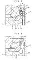
- FIG. 1 is a cross-sectional view of the same rolling bearing unit.
- the left side represents the side toward the vehicle outside and the right side represents the side toward the vehicle inside.
- An outer ring 1 is made of metal such as high-carbon steel meeting JIS S55C or bearing steel meeting JIS SUJ-2, and is a fixed ring fixed to the body of a vehicle such as an automobile.
- the outer ring 1 comprises a flange portion 14 for vehicle body fixing for supporting the outer ring 1 on a suspension system (not shown) at the outer peripheral surface roughly in the center thereof in the axial direction.
- the ring 1 also comprises outer ring raceways 12 and 13 on its inner peripheral surface on the vehicle outward side and the vehicle inward side respectively.
- a hub spindle 2 constitutes a ring that rotates with respect to the outer ring 1.
- the hub spindle 2 comprises a flange portion 15 for wheel fixing at the outer peripheral surface on the vehicle outward side.
- the hub spindle 2 also comprises an inner ring raceway 16 opposite the outer ring raceway 12 at an outer peripheral surface more inward than the flange portion 15.
- An inner ring 3 is outwardly fitted to the outer peripheral surface of a small-diameter cylindrical portion 2a on the side toward the vehicle inward side of the hub spindle 2 and is capable of rotating unitarily with the hub spindle 2.
- the inner ring 3 thus constitutes a ring that rotates together with the hub spindle 2 with respect to the outer ring 1.
- the inner ring 3 comprises an inner ring raceway 17 opposite the outer ring raceway 13 on the outer peripheral surface.
- the inner ring 3 is prevented from slipping out by a bent edge section 2b on the side of the hub spindle 2 toward the vehicle inward side, and is pre-pressured thereby.
- a plurality of balls 4 and 5 are rotatably held between the outer ring raceways 12 and 13 and the inner ring raceways 16 and 17 by cages 6 and 7 respectively.
- a seal 8 is interposed between the inner peripheral surface of the vehicle outward edge section of the outer ring 1 and the outer peripheral surface of the hub spindle 2.
- the rolling bearing unit comprises a resin-made cover 11.
- the cover 11 is cylindrical and has a bottom, at an opening 1b of an edge section 1a on the side of the outer ring 1 toward the vehicle inward side.
- the cover 11 comprises a circular plate portion 20 which covers the opening 1b of the vehicle inward side edge section 1a of the outer ring 1.
- a cylindrical portion 21 of the cover 11 is inwardly press-fitted to the inner peripheral surface of the opening 1b.
- a flange portion 22 of the cover is provided at the periphery of the circular plate portion 20 and restricts the inner fitting depth of the cylindrical portion 21 with respect to the inner peripheral surface of the opening 1b of the outer ring 1.
- most of the entire cover 11 is formed of a resin.
- a metal ring body 25 is integrally provided at the inner peripheral surface of the cylindrical portion 21.
- the material of the ring body 25 is a cold-rolled steel sheet meeting such standards as JIS SPCC.
- only the cylindrical portion 21 may be formed of resin.
- the structure of the cover 11 shall be described in more detail. Illustrated is the positional relationship in the axial direction between the vehicle inward side edge 1a of the outer ring 1 and the vehicle inner side edge 2b of the hub spindle 2. As a result of this relationship, the axial-direction length B of the inner peripheral surface of the cylindrical portion 21 of the cover 11 is made longer than the axial-direction length A of the outer peripheral surface thereof.
- the tip side of the cylindrical portion 21 in the press fitting direction contracts and is easily deformed into a cone shape. This is because the cylindrical portion 21 is made of resin and the outer ring 1 is metal.
- vehicle outward side end face 25a of the ring body 25 is positioned so as to be in the same plane radially with the vehicle outward side end face 21a of the cylindrical portion 21. Furthermore, the end face 25b on the vehicle inward side is positioned more to the vehicle outside than the vehicle inward side root portion 21 b of the outer peripheral surface of the cylindrical portion 21.
- the ring body 25 stops force acting radially inward on the cylindrical portion 21 and prevents the cylindrical portion 21 from being deformed into a cone shape.
- the vehicle inward side edge section 25b on the ring body 25 is positioned more to the vehicle outward side than the vehicle inward side root portion 21 b of the cylindrical portion 21.
- the ring body 25 is provided at the inner peripheral surface of the cylindrical portion 21. Accordingly, the diameter of the cylindrical portion 21 expands by the thermal expansion of the ring body 25 and the outer peripheral surface of the cylindrical portion 21 makes close contact with the inner peripheral surface of the outer ring 1, thereby preventing occurrence of the gap.
- the material of the cover 11 is preferably a resin which has a coefficient of linear expansion approximately that of the material of the outer ring 1.
- examples are polyamide (PA), polyphenylene sulfide (PPS), and polybutylene terephthalate (PBT).
- PA polyamide
- PPS polyphenylene sulfide
- PBT polybutylene terephthalate
- the ring body 25 may also be insert-formed at the cylindrical portion 21 so as to cross the whole inner peripheral surface of the cylindrical portion 21 of the cover 11.
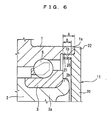
- the resin cover 11 attached to the opening 1b of the vehicle inward side edge section 1a of the outer ring 1 comprises the cylindrical portion 21.
- the cylindrical portion 21 is fitted into the inner peripheral surface of the opening 1b of the vehicle inward side edge section 1a of the outer ring 1.
- the cover 11 also includes the flange portion 22 which contacts an end face 1 c of the vehicle inner side edge section 1a of the outer ring 1.
- the metal ring body 25 is provided at the inner peripheral surface of the cylindrical portion 21.
- the ring body 25 is extended from an inner peripheral surface area S1 of the cylindrical portion 21 to an inner peripheral surface area S2 of the flange portion 22.
- the cover 11 is attached to the outer ring 1 so that the flange portion 22 contacts the end face 1c of the vehicle inward side edge section 1a of the outer ring 1 from the axial direction.
- the cylindrical portion 21 of the cover 11 is slightly bent due to its elasticity while being inserted.
- the ring body 25 is fixed to the area from the inner peripheral surface area S 1 of the cylindrical portion 21 of the cover 11 to the inner peripheral surface area S2 of the flange portion 22. Accordingly, some of the elastic bending portion of the cylindrical portion 21 is supported by the rigidity of the ring body 25.
- the ring body 25 could be provided at the inner peripheral surface region of the cylindrical portion 21 of the cover 11. This would make it difficult for the cover to fall off the outer ring even when thermal shock from heating and cooling occurs. Moreover, merely providing the ring body 25 at the inner peripheral surface area of the cylindrical portion 21, depending on the type of resin, results in insufficient adaptation to temperature changes. In this case, there is the danger that the cylindrical portion 21 will deform, reducing the contact area with the inner peripheral surface of the outer ring 1 and degrading pullout force.
- the ring body 25 extends from the inner diameter side area S1 of the cylindrical portion 21 to the inner diameter side area S2 of the flange portion 22. Accordingly, the starting point for bending of the cylindrical portion 21 is separated from the outer ring 1 (which is a heat source), and the amount of metal at the portion where bending occurs is increased. As a result, so the resin bending amount is suppressed.
- a knurled groove or other groove may form at the inner peripheral surface of the vehicle inward side edge section of the outer ring 1.
- the groove may engage the outer peripheral surface of the cylindrical portion 21.
- part of the cylindrical portion 21 resiliently enters the grooved portion. As a result, the cover 11 is effectively prevented from being pulled out of the outer ring 1.
- An opening may be provided for fitting a rotation detection device on the cover 11, and the rotation detection device may be fitted in the opening.
- This rotation detection device detects the rotational speed or the like of the wheel in order to control a vehicle anti-lock brake system (ABS) or a traction control system (TCS). It is advantageous to use the cover 11 as a cover equipped with such a rotation detection device. This is because the cover 11 is unlikely to fall off the outer ring 1 even when a thermal shock such as heating and cooling occurs.
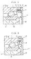
- the axial length B of the inner peripheral surface of the cylindrical portion 21 of the cover 11 is set approximately the same as the axial length A of the outer peripheral surface.
- the axial length B of the inner peripheral surface of the cylindrical portion 21 of the cover 11 is set shorter than the axial length A of the outer peripheral surface.
- the ring body 25 can be disposed with respect to the cylindrical portion 21 in a manner similar to that of FIG. 2 or FIG. 3 . In both configurations, screwing a nut in the hub spindle 2 prevents pullout of the inner ring 3 from the hub spindle 2.
- the present invention is applicable to a rolling bearing unit for rotatably supporting wheels of an automobile or the like on a suspension system.
Landscapes
- Engineering & Computer Science (AREA)
- General Engineering & Computer Science (AREA)
- Mechanical Engineering (AREA)
- Rolling Contact Bearings (AREA)
- Sealing Of Bearings (AREA)
Claims (13)
- Wälzlagereinheit, mit einer Abdeckung (11) an einer Öffnungsseitenkante eines äußeren Rings (1), welche Abdeckung (11) einen kreisförmigen Plattenbereich (20) zur Abdeckung der Außenring-Kantenöffnung (1b) umfasst, dadurch gekennzeichnet, dass die Wälzlagereinheit ferner einen zylindrischen Bereich (21) aus einem Harz umfasst, der in die innere Umfangsfläche der Außenring-Kantenöffnung (1b) eingepasst ist, wobei ein Metallringkörper (25) an der inneren Umfangsoberfläche des zylindrischen Bereichs (21) angebracht ist.
- Wälzlagereinheit gemäß Anspruch 1, bei welcher die axiale Länge des Ringkörpers (25) kürzer ist als die innere Einpasslänge bezüglich der inneren Umfangsfläche der Öffnung (1b) der Außenringkante des zylindrischen Bereichs (21) der Abdeckung (11).
- Wälzlagereinheit gemäß Anspruch 1, bei welcher die Stirnseite (25a) des Ringkörpers (25) in der Einpassrichtung in der radialen Richtung mit der Stirnseite (21a) des Endes des zylindrischen Bereichs (21) abschließt.
- Wälzlagereinheit gemäß Anspruch 1, bei welcher der Ringkörper (25) mit dem zylindrischen Bereich (21) der Abdeckung (11) durch Einsetzformen einteilig ausgebildet ist.
- Wälzlagereinheit gemäß Anspruch 4, bei welcher der Kantenabschnitt (1a) des Ringkörpers (25) in der Einpassrichtung in radialer Richtung nach außen gebogen ist.
- Wälzlagereinheit gemäß Anspruch 1, bei welcher die Abdeckung (11) an einer Öffnung (1b) eines Kantenabschnitts (1a) eines äußeren Rings (1) gegenüberliegend zur Einpassrichtung angebracht ist, und der kreisförmige Plattenbereich (20) die Öffnung (1b) des Kantenabschnitts (1a) des äußeren Rings (1) gegenüberliegend zur Einpassrichtung abdeckt, und der aus Harz geformte zylindrische Bereich (21) nach innen in die innere Umfangsoberfläche der Öffnung (1b) eingepresst ist und die Abdeckung ferner einen Flanschbereich (22) umfasst, der am Umfang des zylindrischen Bereichs (21) vorgesehen ist und die innere Einpasstiefe des zylindrischen Bereichs bezüglich des äußeren Rings (1) festlegt.
- Wälzlagereinheit gemäß Anspruch 6, bei welcher die axiale Länge (B) mit der inneren Umfangsfläche des zylindrischen Bereichs (21) der Abdeckung (11) länger bemessen ist als die axiale Länge (A) von dessen äußerer Umfangsoberfläche,
und die Stirnseite des Ringkörpers (25) in der Einpassrichtung derart angeordnet ist, dass sie in der gleichen radialen Ebene wie die Stirnseite des zylindrischen Bereichs (21) in der Einpassrichtung liegt, und der Kantenabschnitt (1a) gegenüberliegend zur Einpassrichtung weiter in der Einpassrichtung gelegen ist als der gegenüberliegend zur Einpassrichtung angeordnete Basisbereich (21b) einer äußeren Umfangsfläche des zylindrischen Bereichs (21). - Wälzlagereinheit gemäß Anspruch 7, bei welcher die jeweiligen linearen Ausdehnungskoeffizienten des äußeren Rings (1) und des Ringkörpers (25) größer sind als der lineare Ausdehnungskoeffizient des zylindrischen Bereichs (21) der Abdeckung (11).
- Wälzlagereinheit gemäß Anspruch 7, bei welcher das Material der Abdeckung (11) ein Harz ist, mit einem linearen Ausdehnungskoeffizienten in der Nähe desjenigen des Materials des äußeren Rings 1.
- Wälzlagereinheit gemäß Anspruch 6, ferner umfassend:einen äußeren Ring (1) mit einem Flanschbereich (14) zur Fahrzeugbefestigung an einer äußeren Umfangsoberfläche, mit zwei äußeren Ring-Laufflächen (12,13) an einer inneren Umfangsfläche;einer Nabenspindel (2) mit einem Flanschbereich (15) zur Radbefestigung an der äußeren Umfangsfläche in der Einpassrichtung, einer inneren Ring-Lauffläche (16) gegenüberliegend einer äußeren Ring-Lauffläche (12) an der äußeren Umfangsfläche der Nabenspindel (2), welche innere Ring-Lauffläche (16) näher an der Seite gegenüberliegend der Einpassrichtung angeordnet ist als der Flanschbereich (15), wobei ein zylindrischer Bereich kleinen Durchmessers näher zu der Seite gegenüberliegend der Einpassrichtung angeordnet ist als die innere Ring-Lauffläche (16);und eine Dichtung (8) zwischen der inneren Umfangsfläche des Kantenbereichs des äußeren Rings (1) in der Einpassrichtung und der äußeren Umfangsfläche der Nabenspindel (2),wobei der Metallringkörper (25) einteilig an der inneren Umfangsfläche des zylindrischen Bereichs (2a) durch Einsetzformen ausgebildet ist.
- Wälzlagereinheit gemäß Anspruch 10, bei welcher die Stirnfläche des Ringkörpers in der Einpassrichtung derart angeordnet ist, dass sie in der gleichen radialen Ebene liegt wie die Stirnfläche des zylindrischen Bereichs der Abdeckung in der Einpassrichtung, und die Stirnfläche entgegen der Einpassrichtung ist weiter in der Einpassrichtung angeordnet als ein Basisbereich (21b) auf der Seite entgegen der Einpassrichtung an der äußeren Umfangsfläche des zylindrischen Bereichs (21) der Abdeckung.
- Wälzlagereinheit gemäß Anspruch 10, bei welcher der Kantenabschnitt des Ringkörpers (25) in der Einpassrichtung radial nach außen gebogen ist.
- Wälzlagereinheit gemäß Anspruch 10, bei welcher der Kantenabschnitt des Ringkörpers (25) entgegen der Einpassrichtung sich von dem inneren Umfangsoberflächenbereich des zylindrischen Bereichs (21) der Abdeckung (11) zum inneren Umfangsoberflächenbereich des Flanschbereichs (22) erstreckt.
Applications Claiming Priority (3)
| Application Number | Priority Date | Filing Date | Title |
|---|---|---|---|
| JP2003067704 | 2003-03-13 | ||
| JP2003067704 | 2003-03-13 | ||
| PCT/JP2004/003312 WO2004081401A1 (ja) | 2003-03-13 | 2004-03-12 | 転がり軸受ユニット |
Publications (3)
| Publication Number | Publication Date |
|---|---|
| EP1602844A1 EP1602844A1 (de) | 2005-12-07 |
| EP1602844A4 EP1602844A4 (de) | 2006-10-11 |
| EP1602844B1 true EP1602844B1 (de) | 2010-07-07 |
Family
ID=32984568
Family Applications (1)
| Application Number | Title | Priority Date | Filing Date |
|---|---|---|---|
| EP04720208A Expired - Lifetime EP1602844B1 (de) | 2003-03-13 | 2004-03-12 | Wälzlagereinheit |
Country Status (5)
| Country | Link |
|---|---|
| US (1) | US7594758B2 (de) |
| EP (1) | EP1602844B1 (de) |
| JP (1) | JPWO2004081401A1 (de) |
| DE (1) | DE602004027994D1 (de) |
| WO (1) | WO2004081401A1 (de) |
Families Citing this family (13)
| Publication number | Priority date | Publication date | Assignee | Title |
|---|---|---|---|---|
| EP2354580A1 (de) * | 2004-10-01 | 2011-08-10 | Jtekt Corporation | Lagervorrichtung für eine Radnabe |
| JP2006105203A (ja) * | 2004-10-01 | 2006-04-20 | Jtekt Corp | 軸受装置 |
| JP2006112582A (ja) * | 2004-10-18 | 2006-04-27 | Jtekt Corp | 車輪用転がり軸受装置 |
| JP4600004B2 (ja) * | 2004-11-18 | 2010-12-15 | 株式会社ジェイテクト | 車輪用軸受装置 |
| JP2009008210A (ja) * | 2007-06-29 | 2009-01-15 | Kirin Brewery Co Ltd | 軸受装置、及び軸受装置用アダプタ、並びに軸受装置用カバー |
| JP5029318B2 (ja) * | 2007-11-26 | 2012-09-19 | 株式会社デンソー | スタータモータ |
| JP2011149529A (ja) * | 2010-01-25 | 2011-08-04 | Uchiyama Manufacturing Corp | 封止キャップ |
| JP2011121584A (ja) * | 2011-01-12 | 2011-06-23 | Jtekt Corp | 車輪用転がり軸受装置 |
| JP2015113898A (ja) * | 2013-12-11 | 2015-06-22 | 内山工業株式会社 | キャップユニット |
| KR101696905B1 (ko) * | 2015-01-28 | 2017-01-16 | 주식회사 일진글로벌 | 실링 캡 구조 및 이를 이용한 휠 베어링 조립체 |
| JP6964391B2 (ja) * | 2016-03-10 | 2021-11-10 | Ntn株式会社 | 車輪用軸受装置とその製造方法 |
| IT201700099283A1 (it) | 2017-09-05 | 2019-03-05 | Skf Ab | Dispositivo di tenuta per gruppo mozzo-ruota e gruppo mozzo-ruota equipaggiato con tale dispositivo di tenuta |
| CN109835108B (zh) * | 2017-11-29 | 2023-06-30 | 斯凯孚公司 | 用于车辆非驱动轮轮毂总成的端盖 |
Family Cites Families (19)
| Publication number | Priority date | Publication date | Assignee | Title |
|---|---|---|---|---|
| JP2513584Y2 (ja) * | 1990-04-09 | 1996-10-09 | 日本精工株式会社 | 回転速度検出用ハブユニット |
| US5217137A (en) * | 1991-04-22 | 1993-06-08 | Freudenberg-Nok General Partnership | Seal for an end cap |
| US5195807A (en) * | 1992-04-20 | 1993-03-23 | General Motors Corporation | Venting wheel bearing end cap |
| US5296805A (en) * | 1992-08-17 | 1994-03-22 | General Motors Corporation | Serviceable wheel speed sensor with magnet assisted retention |
| US5380103A (en) * | 1993-10-25 | 1995-01-10 | General Motors Corporation | Self tightening venting end cap for vehicle wheel bearing |
| DE4400773A1 (de) * | 1994-01-13 | 1995-07-20 | Teves Metallwaren Alfred | Radlagereinheit mit Drehzahlsensor(en) |
| JPH08184602A (ja) * | 1994-12-28 | 1996-07-16 | Nippon Seiko Kk | 回転速度検出装置付転がり軸受ユニット |
| JP3687199B2 (ja) * | 1996-07-05 | 2005-08-24 | 日本精工株式会社 | 回転速度検出装置付転がり軸受ユニット |
| US5814984A (en) * | 1995-08-22 | 1998-09-29 | Nsk Ltd. | Roller bearing unit having an improved structure for retaining and sealing a cover thereon |
| JP3675006B2 (ja) * | 1995-11-10 | 2005-07-27 | 日本精工株式会社 | 回転速度検出装置付転がり軸受ユニット |
| JPH09287619A (ja) * | 1996-02-23 | 1997-11-04 | Nippon Seiko Kk | 密封装置付転がり軸受ユニット |
| US5816711A (en) * | 1997-09-26 | 1998-10-06 | The Timken Company | Package bearing with retainer |
| JP2000198304A (ja) * | 1998-10-29 | 2000-07-18 | Nsk Ltd | 車輪用転がり軸受ユニット |
| JP4578015B2 (ja) * | 2000-05-31 | 2010-11-10 | 株式会社ジェイテクト | 密封装置ならびに軸受装置 |
| US20020064327A1 (en) * | 2000-10-27 | 2002-05-30 | Koyo Seiko Co., Ltd. | Vehicle-use bearing apparatus |
| JP4218214B2 (ja) * | 2001-02-01 | 2009-02-04 | 株式会社ジェイテクト | 密封装置 |
| JP2003013982A (ja) * | 2001-06-29 | 2003-01-15 | Nsk Ltd | エンコーダ付軸受ユニット |
| DE10207011A1 (de) * | 2002-02-19 | 2003-08-28 | Continental Teves Ag & Co Ohg | Corner-Modul mit einem Sensor |
| WO2005065077A2 (en) * | 2003-10-14 | 2005-07-21 | Ab Skf | Asymmetric hub assembly |
-
2004
- 2004-03-12 US US10/548,913 patent/US7594758B2/en not_active Expired - Lifetime
- 2004-03-12 WO PCT/JP2004/003312 patent/WO2004081401A1/ja not_active Ceased
- 2004-03-12 DE DE602004027994T patent/DE602004027994D1/de not_active Expired - Lifetime
- 2004-03-12 EP EP04720208A patent/EP1602844B1/de not_active Expired - Lifetime
- 2004-03-12 JP JP2005503605A patent/JPWO2004081401A1/ja active Pending
Also Published As
| Publication number | Publication date |
|---|---|
| WO2004081401A1 (ja) | 2004-09-23 |
| EP1602844A1 (de) | 2005-12-07 |
| US7594758B2 (en) | 2009-09-29 |
| EP1602844A4 (de) | 2006-10-11 |
| JPWO2004081401A1 (ja) | 2006-06-15 |
| US20060285786A1 (en) | 2006-12-21 |
| DE602004027994D1 (de) | 2010-08-19 |
Similar Documents
| Publication | Publication Date | Title |
|---|---|---|
| EP0905394B1 (de) | Betriebsfertiges Lager mit Halter | |
| EP1602844B1 (de) | Wälzlagereinheit | |
| JP2005140320A5 (de) | ||
| JP2005140320A (ja) | 駆動輪用ハブユニット | |
| EP1820985A1 (de) | Lagervorrichtung für rad | |
| US6457869B1 (en) | Wheel mounting with axle-mounted sensor | |
| US7267486B2 (en) | Protective cap for wheel support bearing assembly | |
| JP5493307B2 (ja) | 転がり軸受装置 | |
| US8753018B2 (en) | Wheel end support bearing | |
| EP1715202B9 (de) | Lagervorrichtung für ein Antriebsrad eines Fahrzeuges | |
| JP5251922B2 (ja) | 駆動輪用ハブユニット | |
| JP3988576B2 (ja) | 転がり軸受装置 | |
| US12338861B2 (en) | Plain bearing or rolling bearing equipped with a sealing device with a seal seat close to the axis of revolution | |
| EP1801437B1 (de) | Radnaben-Lageranordnung | |
| US12366265B2 (en) | Wheel bearing equipped with a sealing device with gutter and chicane | |
| JP4333116B2 (ja) | 転がり軸受の密封装置 | |
| JP3985617B2 (ja) | 転がり軸受装置 | |
| JP2024504464A5 (de) | ||
| JP2005282767A (ja) | 転がり軸受装置 | |
| JP2004044664A (ja) | 転がり軸受ユニット | |
| JP4693388B2 (ja) | 車輪用軸受装置のセンサ付カバー | |
| JP4829683B2 (ja) | 車輪用軸受装置 | |
| JP3721412B2 (ja) | 自動車用の回転検出器付車輪用軸受組立体 | |
| JP3721413B2 (ja) | 自動車用の回転検出器付車輪用軸受組立体 | |
| JP2024123777A (ja) | 車輪用軸受装置 |
Legal Events
| Date | Code | Title | Description |
|---|---|---|---|
| PUAI | Public reference made under article 153(3) epc to a published international application that has entered the european phase |
Free format text: ORIGINAL CODE: 0009012 |
|
| 17P | Request for examination filed |
Effective date: 20050912 |
|
| AK | Designated contracting states |
Kind code of ref document: A1 Designated state(s): AT BE BG CH CY CZ DE DK EE ES FI FR GB GR HU IE IT LI LU MC NL PL PT RO SE SI SK TR |
|
| AX | Request for extension of the european patent |
Extension state: AL LT LV MK |
|
| RAP1 | Party data changed (applicant data changed or rights of an application transferred) |
Owner name: JTEKT CORPORATION |
|
| DAX | Request for extension of the european patent (deleted) | ||
| RBV | Designated contracting states (corrected) |
Designated state(s): DE FR GB |
|
| A4 | Supplementary search report drawn up and despatched |
Effective date: 20060911 |
|
| 17Q | First examination report despatched |
Effective date: 20070724 |
|
| GRAP | Despatch of communication of intention to grant a patent |
Free format text: ORIGINAL CODE: EPIDOSNIGR1 |
|
| GRAS | Grant fee paid |
Free format text: ORIGINAL CODE: EPIDOSNIGR3 |
|
| GRAA | (expected) grant |
Free format text: ORIGINAL CODE: 0009210 |
|
| AK | Designated contracting states |
Kind code of ref document: B1 Designated state(s): DE FR GB |
|
| REG | Reference to a national code |
Ref country code: GB Ref legal event code: FG4D |
|
| REF | Corresponds to: |
Ref document number: 602004027994 Country of ref document: DE Date of ref document: 20100819 Kind code of ref document: P |
|
| PLBE | No opposition filed within time limit |
Free format text: ORIGINAL CODE: 0009261 |
|
| STAA | Information on the status of an ep patent application or granted ep patent |
Free format text: STATUS: NO OPPOSITION FILED WITHIN TIME LIMIT |
|
| 26N | No opposition filed |
Effective date: 20110408 |
|
| REG | Reference to a national code |
Ref country code: DE Ref legal event code: R097 Ref document number: 602004027994 Country of ref document: DE Effective date: 20110408 |
|
| GBPC | Gb: european patent ceased through non-payment of renewal fee |
Effective date: 20110312 |
|
| PG25 | Lapsed in a contracting state [announced via postgrant information from national office to epo] |
Ref country code: GB Free format text: LAPSE BECAUSE OF NON-PAYMENT OF DUE FEES Effective date: 20110312 |
|
| REG | Reference to a national code |
Ref country code: FR Ref legal event code: PLFP Year of fee payment: 12 |
|
| PGFP | Annual fee paid to national office [announced via postgrant information from national office to epo] |
Ref country code: FR Payment date: 20150309 Year of fee payment: 12 |
|
| REG | Reference to a national code |
Ref country code: FR Ref legal event code: ST Effective date: 20161130 |
|
| PG25 | Lapsed in a contracting state [announced via postgrant information from national office to epo] |
Ref country code: FR Free format text: LAPSE BECAUSE OF NON-PAYMENT OF DUE FEES Effective date: 20160331 |
|
| PGFP | Annual fee paid to national office [announced via postgrant information from national office to epo] |
Ref country code: DE Payment date: 20230131 Year of fee payment: 20 |
|
| REG | Reference to a national code |
Ref country code: DE Ref legal event code: R071 Ref document number: 602004027994 Country of ref document: DE |