EP1602268A2 - Kippanhänger für Aufsitzmäher - Google Patents
Kippanhänger für Aufsitzmäher Download PDFInfo
- Publication number
- EP1602268A2 EP1602268A2 EP05011356A EP05011356A EP1602268A2 EP 1602268 A2 EP1602268 A2 EP 1602268A2 EP 05011356 A EP05011356 A EP 05011356A EP 05011356 A EP05011356 A EP 05011356A EP 1602268 A2 EP1602268 A2 EP 1602268A2
- Authority
- EP
- European Patent Office
- Prior art keywords
- chassis
- tilting
- trailer
- trailer according
- tipping
- Prior art date
- Legal status (The legal status is an assumption and is not a legal conclusion. Google has not performed a legal analysis and makes no representation as to the accuracy of the status listed.)
- Withdrawn
Links
Images


Classifications
-
- A—HUMAN NECESSITIES
- A01—AGRICULTURE; FORESTRY; ANIMAL HUSBANDRY; HUNTING; TRAPPING; FISHING
- A01D—HARVESTING; MOWING
- A01D43/00—Mowers combined with apparatus performing additional operations while mowing
- A01D43/06—Mowers combined with apparatus performing additional operations while mowing with means for collecting, gathering or loading mown material
- A01D43/07—Mowers combined with apparatus performing additional operations while mowing with means for collecting, gathering or loading mown material in or into a trailer
-
- B—PERFORMING OPERATIONS; TRANSPORTING
- B60—VEHICLES IN GENERAL
- B60P—VEHICLES ADAPTED FOR LOAD TRANSPORTATION OR TO TRANSPORT, TO CARRY, OR TO COMPRISE SPECIAL LOADS OR OBJECTS
- B60P1/00—Vehicles predominantly for transporting loads and modified to facilitate loading, consolidating the load, or unloading
- B60P1/04—Vehicles predominantly for transporting loads and modified to facilitate loading, consolidating the load, or unloading with a tipping movement of load-transporting element
- B60P1/06—Vehicles predominantly for transporting loads and modified to facilitate loading, consolidating the load, or unloading with a tipping movement of load-transporting element actuated by mechanical gearing only
-
- B—PERFORMING OPERATIONS; TRANSPORTING
- B60—VEHICLES IN GENERAL
- B60P—VEHICLES ADAPTED FOR LOAD TRANSPORTATION OR TO TRANSPORT, TO CARRY, OR TO COMPRISE SPECIAL LOADS OR OBJECTS
- B60P1/00—Vehicles predominantly for transporting loads and modified to facilitate loading, consolidating the load, or unloading
- B60P1/04—Vehicles predominantly for transporting loads and modified to facilitate loading, consolidating the load, or unloading with a tipping movement of load-transporting element
- B60P1/24—Vehicles predominantly for transporting loads and modified to facilitate loading, consolidating the load, or unloading with a tipping movement of load-transporting element using the weight of the load
-
- B—PERFORMING OPERATIONS; TRANSPORTING
- B60—VEHICLES IN GENERAL
- B60P—VEHICLES ADAPTED FOR LOAD TRANSPORTATION OR TO TRANSPORT, TO CARRY, OR TO COMPRISE SPECIAL LOADS OR OBJECTS
- B60P1/00—Vehicles predominantly for transporting loads and modified to facilitate loading, consolidating the load, or unloading
- B60P1/04—Vehicles predominantly for transporting loads and modified to facilitate loading, consolidating the load, or unloading with a tipping movement of load-transporting element
- B60P1/28—Tipping body constructions
Definitions
- the invention relates to a tipping trailer for ride-on mower, with a chassis and a body mounted thereon.
- the object of the invention is to provide a tipping trailer for ride-on mower, Easy to install and easy to handle and versatile offers.
- An essential feature of the invention is that the structure of a funnel-shaped tub is over ball sockets so on the chassis supported by at least one formed by two of the ball sockets Axis is tiltable.
- the tub Due to the funnel-shaped design of the tub runs at least a wall of this tub obliquely downwards inwards, so that when around a tilted parallel to this wall parallel axis, the emptying of the tub similar it's just like a wheelbarrow.
- An elaborate tailgate construction is not required. Because the tilting axis through two of the ball sockets is formed, the tub is tiltable relative to the chassis, and Consequently, the tilt axis does not need to coincide with the axis of the chassis. This allows the position of the tilt axis and the slope of the Wall of the tub to match so that the load when tilting practically by itself slips out of the tub. Uncoupling the chassis from the lawnmower is not required.
- One of the add-on modules is a volume attachment that looks like a hood on the structure, so the tub, put on, so that the capacity especially for light goods such as leaves, fruit trees and the like is increased while preventing the in and on the tub piled cargo drops or blown away.
- the volume attachment is designed that the tipping the tub to the rear and preferably also to the side is also possible with attached volume attachment.
- a sweeper for collecting grass clippings, leaves and the like a lawn rake or possibly also a lawn fan, a fertilizer spreader and the like.
- the advantage a combination of these additional modules with the tipping trailer consists in particular, that the weight of the tub and possibly the contents of this Can be used to increase the pressure force with which the Add-on module, such as a lawn rake, is pressed against the ground and / or to increase the force with which the wheels of the chassis against pressed the ground, so that the wheels of the chassis when pulling the trailer generate a high torque which is required to drive the additional modules, be used for example a sweeper or Rasenlformaterss can.
- the tipping functions of the tub can also remain with mounted additional modules.
- these can be Tilting functions to use the additional modules from the operating position in to transfer a rest position and vice versa.
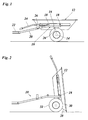
- the trailer shown in Fig. 1 has a uniaxial chassis 10, on which is mounted as a funnel-shaped tray 12 construction.
- the chassis 10 has a tubular frame, the above a wheel axle 14 a stool 16 forms, on which the trough 12 is supported by four ball sockets 18.
- the tubular frame of the chassis is forward to a drawbar 20th extended, which carries a coupling 22 at the front end, so that the trailer To a riding mower, not shown, or a similar small towing machine can be coupled.
- a forwardly projecting tilting rod 24 is mounted laterally. This tilting rod is shown in Fig. 1 by one of the drawbar 20 towering Locking tab 26 overlapped, so that the trough 12 in her Position on the stool 16 is locked.
- the tilting rod 24 which can be deflected elastically to a certain extent can be adjusted however, pivot away from the seat mower seat under the locking tab 26 and then lift so that the tub 12 relative to the chassis 10 is tilted back to the position shown in FIG.
- the tilt axis is formed by the two rear ball cups 18 and is slightly behind the center of gravity of the tub 12, so that the tub on the one hand in the transport position shown in Fig. 1 rests stable on the stool, on the other hand However, only a small force is required for tilting the tub.
- the inclination of the rear wall 28 of the tub and the height of the tilt axis over the wheel axle 14 are selected so that the cargo in the tilted Position by itself slip out of the tub. If necessary, can The cargo also with a broom or a shovel easily from the Be scratched out tub.
- the tilt angle is about 90 °, so that the Bottom of the tub in Fig. 2 is almost vertical.
- the side walls 30 of the tub 12 are inclined and arranged so that they in the tilted position of FIG. 2 at the Rubber tires of the wheels 32 of the chassis abut.
- the rubber tires can be used as a crash cushion when tipping.
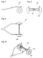
- FIG. 3 and 4 the chassis 10 is shown without the wheel axle and the wheels.
- the exact geometry of the drawbar 20 and the stool 16 forming Tubular frame can be seen in the drawings.
- the stool 16 is based on two support brackets 34, which are connected by a crossbar 36 are and make bearings 38 for the wheel axle.
- Each support trestle will make as well an upwardly open circular arcuate slot 40 ( Figure 3) concentric to the bearing 38 runs.
- the ball pans 18 are in the shape of a rectangle on the stool 16th arranged.
- one of the ball sockets 18 is enlarged and perspective and shown in a vertical section.
- the ball socket has the shape of a vertical cylinder and forms an upwardly open bearing shell 42 with hemispherical bottom.
- In the peripheral wall of the bearing shell 42 are an eccentric transverse bore 44 and an upwardly open U-shaped Recess 46 formed.
- the tub 12 has for each ball socket 18 a horizontally projecting bearing pin 48 on, the one at the free end Ball 50 carries ( Figure 6).
- the ball 50 is fitting in the bearing shell 42, so that the shank of the bearing pin 48 received in the recess 46 becomes.
- the bearing pin 48 is thus relative to the ball socket on the one hand to his Rotatable longitudinal axis and on the other hand to a perpendicular to the plane pivotable in Fig. 6 by the center of the ball 50 extending axis, wherein the shaft exits from the recess 46.
- Fig. 7 to 10 show the complete chassis 10 including the wheel axle 14 and wheels 32 in different views and leave the exact recognize spatial arrangement.
- Fig. 11 to 14 show in different views the exact construction of Pan 12.
- the top and bottom of the pan 12 are in a horizontal position, form the rear wall 28 and the front wall of the tub with the vertical each an angle ⁇ of 40 °.
- the side walls 30 of the trough form the vertical, respectively an angle ⁇ of 43 °.
- Figs. 12 and 13 also show that the front end of the tilting rod 24 something angled inwards. This also allows the tub to a Longitudinal axis passing through the front and rear ball pans on the side the tilt rod 24 extends to tilt to the side. For this purpose, the balls 50th be unlocked on the opposite side. As shown in FIG. 11, the Tilting rod 24 and arranged on this side of the tub balls 50 so attached to a common mounting rail 52 that the rear portion the tilting rod on the tilt axis defined by the balls 50 lies. Therefore, the tilting rod does not need for the lateral tilting Locking tab 26 (Fig. 1 and 4) to be solved.
- Figure 15 shows a rear view of the trailer with the pan tipped sideways 12. Also in this case allows the inclined side wall 30 of the tub a simple emptying, and the rubber tires of the wheels 32 forms a shock-absorbing stop for the edge of the tub, so that the tilting movement is limited.
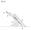
- Fig. 16 illustrates a further tilting possibility, in which the trough 12 together is tilted with the chassis 10 about the wheel axle 14. This must be the Clutch 22 are released from the towing vehicle, so that the drawbar 20 with high can swing.
- the rear wall 28 of the tub is then practically flat the ground up. This allows easy loading of the trailer with heavy loads such as rocks, tree roots and the like.
- the burden is simply rolled or pushed onto the back wall 28 of the tub and then with the drawbar 20 levered up over a long lever arm.
- Optionally can be mounted on the drawbar 20 is a known floor support, the holding the trailer in a nearly horizontal position and hitching facilitated to the towing vehicle.
- tub 12 Due to the described design and support of the tub 12 offers The trailer thus diverse tilting possibilities.
- the ball pans allow In addition, a simple assembly and disassembly of the tub.
- a variety of trailers can trade in the tubs be stacked to save space, and on the part of the dealer can be the Then very easy to mount tubs on the chassis.
- Also for the End user has the advantage of easy assembly and disassembly, that the trailer easily disassembled when not in use, such as in winter and can be stowed away to save space.
- the tub can be 12 also used detached from the chassis as a container.
- the tub in preferably continuously adjustable positions as well an electric actuator or a lockable gas spring 26 'is provided be, the z. B. be hinged to one of the support blocks 34 and the tub 12 can, as indicated by dash-dotted lines in Fig. 1.
- the volume attachment 54 has the shape of a side view of a trapezoidal hood and can be releasably, preferably with hinges, on an edge flange of Secure tray 12.
- the supporting structure of the volume attachment is by a plug-in frame with two trapezoidal frame profiles 56 formed, which are interconnected by transverse profile bars 58 (Fig. 18).
- linings in the form of tent towels or air-permeable nets are also for baskets of lawnmowers be used.
- the lateral frame profiles 56 closed by side cloths 60, the edge with tent springs in corresponding Grooves of the frame profiles 56 are held.
- a cover sheet 62 (Fig. 18) is in turn guided with tent springs between the two frame profiles 56 or alternatively with clips releasably attached to the frame profiles.
- the cover sheet 62 slants the rear sloping leg of the trapezoidal volume structure open, so that there a filling or Auskippö réelle 64 is formed.
- a volume attachment 54 is also attached Side tipping possible.
- the frame construction of the volume attachment 54 In this case, hinged parts 66 ( Figure 21) are attached to the upper longitudinal edge attached to the tub 12, which is opposite to the tilting rod 24. On the opposite Side of the volume attachment is loose, so that it when tilting unfolds by itself and forms a lateral Auskippö réelle 68.
- the side walls of the volume attachment also converge diagonally upwards, so that the automatic Expanding the volume attachment when side tipping even stronger the weight of the dumped material is supported.
- Figs. 24 and 25 show an embodiment in which as another additional module a sweeper 70 is attached to the chassis 10.
- the sweeper 70 is supported with support rollers 72 on the ground and is with the Trough 12 on the side of the tilting rod 24 by a chain, a tension spring 74th or the like, so that they the tub in a slightly tilted position pulls, as shown in Fig. 24.
- the tilting axis is thereby as in FIG. 2 formed by the rear ball pans 18.
- the rear opening 64 of the volumetric attachment 54 serves in this case as a throw-in opening, through which the Kehrgut collected by the sweeper 70 directly into the tub or the volume tower is thrown.
- the drive of the sweeper is done over at least one of the wheels 32 of the chassis.
- FIG. 26 to 29 the sweeper 70 is shown separately.
- a brush 76 is rotatably mounted in a housing 78 and is connected to a on a End of the brush arranged pinion 80 of a chain drive driven. From the chain drive is in the drawing except the pinion 80 only one Protective cover 82 is shown.
- a frame 86 ( Figure 28) is on front end provided with longitudinally adjustable studs 88 and serves for adjustable coupling of the sweeper to the chassis 10.
- the adjustable Stud bolt 88 and a slot 90 in the protective trim 82nd ( Figure 26) allow the spacing between the pinions 80, 84 to be varied and so adjust the chain tension.
- the stud bolts 88 are inserted into the slots 40 of the support brackets 34 mounted, which are shown in Fig. 3.
- the front sprocket 84 of the chain drive is still in the protective fairing 82 is received, and a chain not shown is on both pinion 80, 84 raised.
- the protective cover 82 is resiliently mounted on the housing 78th held on the sweeper and is laterally on the end of the wheel axle 14 of the chassis attached, with a rotationally fixed connection between the front pinion 84 and the wheel axle 14 is made.
- the wheel axle 14 is a rotatable shaft which is not shown freewheel hubs so coupled with the two wheels 32 of the chassis that they driven by these wheels, but also run faster than the wheels can. When cornering thus the shaft is like a differential gear each driven by the faster of the two wheels.
- the brush 76 is the chain drive through the Wheels 32 of the chassis are driven in the same direction as these wheels.
- the different diameters of the pinions 80, 84 cause a translation in quick, so that the brush opposite the ground sweeps to the direction and turns away.
- the dirt is through the Rear wall of the housing 78 deflected and thrown into the tub 12. Because the Brush 76 is driven by both wheels 32 of the chassis and also the wheels by the weight of the tub 12 and possibly the contents firmly against be pressed against the ground, can be without active drive on a PTO or the like generate a high driving torque.
- the support wheels 72 are height adjustable on the housing 78 of the sweeper arranged so that adjust the height of the brush 76 on the floor leaves.
- the support wheels 72 are height adjustable on the housing 78 of the sweeper arranged so that adjust the height of the brush 76 on the floor leaves.
- the attachment and removal of the sweeper 70 is carried out expediently in the in FIG 30 shown raised position. In this position, the assembly process facilitated by the lower chain tension. If then the sweeper by tilting the tub 12 in the operating position shown in Figure 25 is lowered, the chain is automatically re-tensioned.
- the volume structure 54 allows a high capacity when collecting of the sweepings.
- the tub 12 In the position shown in Fig. 30, the tub 12 be emptied even with attached sweeper 70 by side tipping, as shown in FIGS. 20 to 23. This is possible because of the chain or Tension spring 74 (Fig. 24) on the same side as the tilt rod 24 is located.
- a lawn comb 90 is shown as a further additional module with the the lawn can be raked off or ventilated. Since the lawn crest 90 ago the wheel axle of the chassis and thus arranged in front of the sweeper 70 is, can be mowed, ventilated and turned away in one go, where the grass clippings and the moss loosened by the lawn crest the sweeper are transported in the trailer. Alternatively, it is also possible, in a first operation with mower off Lawn mower and inactive sweeper (position shown in FIG. 30) the lawn to rake off to get larger twigs and other debris from the lawn remove, smooth moles and the like, and then in a second operation to mow and sweep. If only raked should be, of course, the sweeper 70 and possibly also the tub 12 to be dismantled.
- Fig. 31 the grass ridge 90 is shown separately.
- the lawn crest points a base plate 92 which is equipped with a plurality of resilient prongs 94.
- several attachable base plate modules can be provided so that the number of tines can be varied.
- the base plate 92 hinged and thus height adjustable with the support blocks 34 (Fig. 3) of the chassis 10.
- the rockers 96 are hinged to brackets 98, and they engage with studs 100 in arcuate slots 102 of the bracket one.
- the slotted holes 102 may be horizontally, i.e., parallel, to the base plate 92 be aligned to the lawn.
- a latching plate 104th attached, for example detachably clamped, to which a right angled and between different locking positions pivotable lever 106 is stored.
- the free rear end of the control lever 106 is over a tension spring 108 (FIG. 30) is connected to the base plate 92.
- the pivot axis of the adjusting lever 106 in the latching plate 104 and thus in the immediate vicinity of the Clutch 22 is located can be a high pressure even when the trailer is unloaded generate, and the chassis of the trailer serves primarily to move the grass comb in a position parallel to the ground hold. Uneven floors can be compensated by the tension spring 108.
- the lever 106 is pulled all the way forward, so the grass comb 90 is moved via the tension spring 108 into an inoperative position raised.
- the lever 106 can be from the driver's seat of the lawnmower serve.
- Figs. 32 and 33 show the trailer with all the additional modules in the Operating position for combined raking and sweeping.
- the grass comb may also be in front of the Brush 76 be integrated into the housing 78 of the sweeper, so that he can raise and lower together with the sweeper 70.
Landscapes
- Engineering & Computer Science (AREA)
- Transportation (AREA)
- Mechanical Engineering (AREA)
- Life Sciences & Earth Sciences (AREA)
- Environmental Sciences (AREA)
- Harvester Elements (AREA)
Abstract
Description
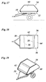
- Fig. 1
- eine Seitenansicht des Kippanhängers;
- Fig. 2
- eine Seitenansicht des Kippanhängers in nach hinten gekippter Stellung;
- Fig. 3 und 4
- eine Seitenansicht bzw. eine perspektive Ansicht eines Fahrgestells des Kippanhängers ohne Achse und Räder;
- Fig. 5 und 6
- eine perspektivische Ansicht und einen Schnitt durch eine Kugelpfanne;
- Fig. 7 bis 10
- das Fahrgestell mit Achse und Rädern in einer Seitenansicht, einer Frontansicht, einer Draufsicht und einer perspektivischen Ansicht;
- Fig. 11 bis 14
- eine den Aufbau des Kippanhängers bildende Wanne in einer Seitenansicht, Frontansicht, Draufsicht und perspektivischen Ansicht;
- Fig. 15
- eine Rückansicht des Kippanhängers mit seitlich gekippter Wanne;
- Fig. 16
- eine Seitenansicht des Kippanhängers in einer Kippstellung für das Beladen mit schweren Transportgütern;
- Fig. 17 bis 19
- den Kippanhänger mit einem Volumenaufsatz in einer Seitenansicht, einer Draufsicht und einer perspektivischen Ansicht;
- Fig. 20 bis 23
- eine Seitenansicht, Frontansicht, Draufsicht und perspektivische Ansicht des Kippanhängers in seitlich gekippter Stellung mit Volumenaufsatz;
- Fig. 24 und 25
- eine Seitenansicht und eine perspektivische Ansicht des Kippanhängers mit Volumenaufsatz und einer Kehrmaschine als weiterem Zusatzmodul;
- Fig. 26 bis 29
- die Kehrmaschine in einer Seitenansicht, Frontansicht, Draufsicht und perspektivischen Ansicht;
- Fig. 30
- eine Seitenansicht des Kippanhängers mit Volumenaufsatz, Kehrmaschine und einer Rasenharke als weiterem Zusatzmodul;
- Fig. 31
- eine gesonderte Darstellung der Rasenharke; und
- Fig. 32 und 33
- eine Seitenansicht bzw. eine perspektivische Ansicht des Kippanhängers mit Zusatzmodulen in der Betriebsstellung für die Kehrmaschine.
Claims (21)
- Kippanhänger für Aufsitzmäher, mit einem Fahrgestell (10) und einem darauf montierten Aufbau, dadurch gekennzeichnet, daß der Aufbau eine trichterförmige Wanne (12) ist, die sich über Kugelpfannen (18) so auf dem Fahrgestell (10) abstützt, daß sie um mindestens eine durch zwei der Kugelpfannen (18) gebildete Achse kippbar ist.
- Kippanhänger nach Anspruch 1, dadurch gekennzeichnet, daß die Wanne (12) eine schräge Rückwand (18) und mindestens eine schräge Seitenwand (30) aufweist und daß mindestens drei Kugelpfannen (18) so auf dem Fahrgestell (10) angeordnet sind, daß sie zwei zueinander rechtwinklige Kippachsen für die Wanne (12) definieren.
- Kippanhänger nach Anspruch 1 oder 2, dadurch gekennzeichnet, daß das Fahrgestell (10) gummibereifte Räder (32) aufweist, die für die Wanne (12) einen stoßdämpfenden Anschlag zur Begrenzung der Kippbewegung um mindestens eine der Kippachsen bilden.
- Kippanhänger nach einem der vorstehenden Ansprüche, dadurch gekennzeichnet, daß an der Wanne (12) eine nach vorn vorspringende Kippstange (24) angeordnet ist.
- Kippanhänger nach Anspruch 4, dadurch gekennzeichnet, daß die Kippstange (24) an einer Seite der Wanne (12) angebracht und in ihrem nach vorn über die Wanne (12) überstehenden Teil nach innen abgewinkelt ist.
- Kippanhänger nach Anspruch 4 oder 5, dadurch gekennzeichnet, daß die Kippstange (24) an einer an einer Deichsel (20) des Fahrgestells (10) angebrachten Verriegelungslasche (26) verriegelbar ist, um die Wanne (12) in ihrer nicht gekippten Stellung zu fixieren.
- Kippanhänger nach Anspruch 2 und einem der Ansprüche 4 bis 6, dadurch gekennzeichnet, daß der von der Verriegelungslasche (26) erfaßte Teil der Kippstange (24) auf einer Linie mit zweien der Kugelpfannen (18) liegt, die eine Kippachse für das Seitenkippen definieren.
- Kippanhänger nach einem der vorstehenden Ansprüche, dadurch gekennzeichnet, daß das Fahrgestell (10) eine einzige Radachse (14) aufweist und daß die Wanne (12) so am Fahrgestell (10) angeordnet ist, daß die Wanne (12) und das Fahrgestell (10) gemeinsam um die Radachse (14) in eine Position schwenkbar sind, in der die geneigte Rückwand (28) der Wanne flach auf dem Boden aufliegt.
- Kippanhänger für Aufsitzmäher, mit einem Fahrgestell (10) und einem darauf montierten Aufbau (12), insbesondere nach einem der vorstehenden Ansprüche, gekennzeichnet durch einen lösbaren, auf den Aufbau (12) aufsetzbaren Volumenaufsatz (54), der eine tragende Konstruktion in der Form eines Rahmengestells (56, 58) aufweist.
- Kippanhänger nach Anspruch 9, dadurch gekennzeichnet, daß der Volumenaufsatz (54) durch an der Rahmenkonstruktion (56, 58) gehaltene Seitentücher (60) und/oder ein Decktuch (62) verkleidet ist.
- Kippanhänger nach Anspruch 10, dadurch gekennzeichnet, daß das Decktuch (62) eine rückwärtige Auskippöffnung (64) freiläßt.
- Kippanhänger nach einem der Ansprüche 9 bis 11, dadurch gekennzeichnet, daß der Volumenaufsatz (54) auf einer Seite des Aufbaus (12), die einer Seitenkippachse des Aufbaus gegenüberliegt, über Scharnierteile (66) so mit dem oberen Rand des Aufbaus verbunden ist, daß er beim Kippen des Aufbaus (12) um die Seitenkippachse aufklappt und eine seitliche Auskippöffnung (68) freigibt.
- Kippanhänger für Aufsitzmäher, mit einem Fahrgestell (10) und einem darauf montierten Aufbau (12), insbesondere nach einem der vorstehenden Ansprüche, gekennzeichnet durch eine lösbar am Fahrgestell (10) montierten Kehrmaschine (70), die durch mindestens ein Rad (32) des Fahrgestells (10) antreibbar ist.
- Kippanhänger nach Anspruch 13, dadurch gekennzeichnet, daß der Antrieb der Kehrmaschine (70) über eine Welle erfolgt, die zugleich die Radachse (14) des einachsigen Anhängers bildet und über Freilaufnaben mit beiden Rädern (32) des Anhängers gekoppelt ist.
- Kippanhänger nach Anspruch 13 oder 14, dadurch gekennzeichnet, daß die Kehrmaschine (70) dazu ausgebildet ist, an der Rückseite des Kippanhängers montiert zu werden und das Kehrgut in den Aufbau (12) auszuwerfen.
- Kippanhänger nach einem der Ansprüche 13 bis 15, dadurch gekennzeichnet, daß zum Antrieb der Kehrmaschine (70) ein Riemen- oder Kettentrieb (80, 82, 84) vorgesehen ist und daß die Kehrmaschine mit dem Fahrgestell (10) über einen Rahmen (86) verbunden ist, der mit Stehbolzen (88) in Schlitze (40) des Fahrgestells eingreift, die kreisbogenförmig um die Radachse (14) des Fahrgestells verlaufen.
- Kippanhänger nach einem der Ansprüche 13 bis 16, dadurch gekennzeichnet, daß die Kehrmaschine (70) schwenkbar am Fahrgestell (10) angebracht und durch ein Zugglied (74) so mit dem Aufbau (12) gekoppelt ist, daß sie durch Kippen des Aufbaus zwischen einer Betriebsstellung und einer Ruhestellung verschwenkbar ist.
- Kippanhänger für Aufsitzmäher, mit einem Fahrgestell (10) und einem darauf montierten Aufbau (12), insbesondere nach einem der vorstehenden Ansprüche, gekennzeichnet durch einen lösbar am Fahrgestell (10) montierten Rasenkamm (90).
- Kippanhänger nach einem der Ansprüche 13 bis 17 und nach Anspruch 18, dadurch gekennzeichnet, daß der Rasenkamm (90) in Fahrtrichtung vor der Kehrmaschine (70) angeordnet ist.
- Kippanhänger nach Anspruch 18 oder 19, dadurch gekennzeichnet, daß der Rasenkamm (90) über mindestens eine Schwinge (96) schwenkbar mit dem Fahrgestell (10) verbunden und über eine Zugfeder (108) mit einem schwenkbar an einer Deichsel (20) des Kippanhängers angebrachten Stellhebel (106) verbunden ist, der zur Einstellung der Höhe des Rasenkamms (90) über dem Boden und/oder zur Einstellung der Andruckkraft des Rasenkamms gegen den Boden in unterschiedlichen Raststellungen arretierbar ist.
- Kippanhänger nach einem der Ansprüche 18 bis 20, dadurch gekennzeichnet, daß der Rasenkamm (90) in unterschiedlichen Neigungswinkeln relativ zur Schwinge (96) fixierbar ist.
Applications Claiming Priority (2)
| Application Number | Priority Date | Filing Date | Title |
|---|---|---|---|
| DE200420008853 DE202004008853U1 (de) | 2004-06-03 | 2004-06-03 | Kippanhänger für Aufsitzmäher |
| DE202004008853U | 2004-06-03 |
Publications (2)
| Publication Number | Publication Date |
|---|---|
| EP1602268A2 true EP1602268A2 (de) | 2005-12-07 |
| EP1602268A3 EP1602268A3 (de) | 2006-02-15 |
Family
ID=34936932
Family Applications (1)
| Application Number | Title | Priority Date | Filing Date |
|---|---|---|---|
| EP05011356A Withdrawn EP1602268A3 (de) | 2004-06-03 | 2005-05-25 | Kippanhänger für Aufsitzmäher |
Country Status (2)
| Country | Link |
|---|---|
| EP (1) | EP1602268A3 (de) |
| DE (1) | DE202004008853U1 (de) |
Cited By (1)
| Publication number | Priority date | Publication date | Assignee | Title |
|---|---|---|---|---|
| USD1108765S1 (en) | 2022-07-08 | 2026-01-06 | Js Products, Inc. | Garden cart |
Families Citing this family (1)
| Publication number | Priority date | Publication date | Assignee | Title |
|---|---|---|---|---|
| DE102018102836A1 (de) * | 2018-02-08 | 2019-08-08 | Msd Ag | Verfahren und Vorrichtung zur Bekämpfung invasiver Neophyten im Erdreich sowie zur Hygienisierung von Boden-Mischsubstraten |
Family Cites Families (12)
| Publication number | Priority date | Publication date | Assignee | Title |
|---|---|---|---|---|
| DE407223C (de) * | 1921-03-08 | 1924-12-17 | Benz & Cie | Kippwagen |
| DE2621783A1 (de) * | 1976-05-15 | 1977-12-08 | Fritz Seibold | Verbindung zwischen einer zugmaschine und einem anhaenger |
| US4158279A (en) * | 1977-04-05 | 1979-06-19 | Mcdonough Power Equipment, Inc. | Riding mower with grass collecting system |
| US4699393A (en) * | 1984-09-07 | 1987-10-13 | Schweigert James R | Multi-purpose trailer with universal mounting hitch |
| DE3437670A1 (de) * | 1984-10-13 | 1986-04-17 | Stadler Fahrzeugwerk und Behälterbau GmbH & Co, 7910 Neu-Ulm | Einachsanhaenger mit hilfsvorrichtung zum be- und entladen |
| DE8908190U1 (de) * | 1988-07-05 | 1989-11-02 | Wiedenmann Gmbh, 7901 Rammingen | Kehrmaschine |
| US4922696A (en) * | 1989-01-19 | 1990-05-08 | The Murray Ohio Manufacturing Company | Grass collecting/utility cart for riding lawn mower |
| US5080442A (en) * | 1989-02-21 | 1992-01-14 | Brinly-Hardy Co., Inc. | Collector cart |
| NL1003505C1 (nl) * | 1996-07-04 | 1998-01-07 | Hkh Aanhangwagens | Allestransporter met een links- en rechtszijdige kipper. |
| US6463724B1 (en) * | 1998-12-03 | 2002-10-15 | Rex Payne | Collection device for grass and sprigs |
| US6237313B1 (en) * | 1999-08-13 | 2001-05-29 | Deere & Company | Grass catcher support assembly for reel mower cutting unit |
| ITBS20020076U1 (it) * | 2002-06-11 | 2003-12-11 | O M F B S P A Hydraulic Compon | Dispositivo di ribaltamento trilaterale del cassone di veicoli industriali |
-
2004
- 2004-06-03 DE DE200420008853 patent/DE202004008853U1/de not_active Expired - Lifetime
-
2005
- 2005-05-25 EP EP05011356A patent/EP1602268A3/de not_active Withdrawn
Cited By (1)
| Publication number | Priority date | Publication date | Assignee | Title |
|---|---|---|---|---|
| USD1108765S1 (en) | 2022-07-08 | 2026-01-06 | Js Products, Inc. | Garden cart |
Also Published As
| Publication number | Publication date |
|---|---|
| DE202004008853U1 (de) | 2005-10-20 |
| EP1602268A3 (de) | 2006-02-15 |
Similar Documents
| Publication | Publication Date | Title |
|---|---|---|
| EP0387794A1 (de) | Selbstfahrendes Nutzfahrzeug für die Strandreinigung | |
| EP0324974B1 (de) | Vorrichtung zum frontseitigen Anbau eines Arbeitsgerätes an einen Kleinschlepper, insbesondere Rasen- und Gartenschlepper | |
| DE2025597A1 (de) | Kehr- oder Mähmaschine mit gelenkig am Chassis angebrachtem Fangkorb | |
| EP0016440B1 (de) | Mähvorrichtung | |
| EP0576979B1 (de) | Vorrichtung zum Sichern eines kippbaren Teils in einer ersten Stellung und in einer Kippstellung | |
| EP0468362B1 (de) | Vorrichtung zum seitlichen Anschliessen eines Sammelbehälters an ein Fahrzeug | |
| DE966154C (de) | Landwirtschaftliches, motorisch angetriebenes Fahrzeug | |
| DE102011009708B4 (de) | Spielzeug-Anhänger | |
| EP1602268A2 (de) | Kippanhänger für Aufsitzmäher | |
| DE6604906U (de) | Heuwerbungsmaschine. | |
| DE2160825A1 (de) | Heuwerbungsmaschine | |
| EP2484195B1 (de) | Erntefahrzeug | |
| DE2046552A1 (de) | Schlepper mit verschiebbarem Fahrer sitz | |
| DE2319308C2 (de) | Maschine zum Ausbringen von verteilbarem Material | |
| DE1966494A1 (de) | Schlepper | |
| DE2508481A1 (de) | Bodenbearbeitungsmaschine | |
| CH650638A5 (de) | Kreisel-heuwerbungsmaschine. | |
| EP2640178A1 (de) | Vorrichtung zum streifenförmigen aufbringen von düngemittel | |
| CH623198A5 (de) | ||
| DE3504654A1 (de) | Bodenbearbeitungsmaschine, insbesondere kreiselegge | |
| DE1939539A1 (de) | Ladewagen | |
| BE1031908B1 (de) | Erntevorsatz für eine selbstfahrende Erntemaschine | |
| DE20104155U1 (de) | Handkarre mit Lastaufnahmeeinheit | |
| DE20304323U1 (de) | Mischgerät | |
| DE69716938T2 (de) | Landwirtschaftliche erntemaschine |
Legal Events
| Date | Code | Title | Description |
|---|---|---|---|
| PUAI | Public reference made under article 153(3) epc to a published international application that has entered the european phase |
Free format text: ORIGINAL CODE: 0009012 |
|
| AK | Designated contracting states |
Kind code of ref document: A2 Designated state(s): AT BE BG CH CY CZ DE DK EE ES FI FR GB GR HU IE IS IT LI LT LU MC NL PL PT RO SE SI SK TR |
|
| AX | Request for extension of the european patent |
Extension state: AL BA HR LV MK YU |
|
| PUAL | Search report despatched |
Free format text: ORIGINAL CODE: 0009013 |
|
| AK | Designated contracting states |
Kind code of ref document: A3 Designated state(s): AT BE BG CH CY CZ DE DK EE ES FI FR GB GR HU IE IS IT LI LT LU MC NL PL PT RO SE SI SK TR |
|
| AX | Request for extension of the european patent |
Extension state: AL BA HR LV MK YU |
|
| AKX | Designation fees paid | ||
| STAA | Information on the status of an ep patent application or granted ep patent |
Free format text: STATUS: THE APPLICATION IS DEEMED TO BE WITHDRAWN |
|
| 18D | Application deemed to be withdrawn |
Effective date: 20060817 |
|
| REG | Reference to a national code |
Ref country code: DE Ref legal event code: 8566 |