EP1600539A2 - Procédé et dispositif d'affichage pour métier à tisser - Google Patents
Procédé et dispositif d'affichage pour métier à tisser Download PDFInfo
- Publication number
- EP1600539A2 EP1600539A2 EP05008994A EP05008994A EP1600539A2 EP 1600539 A2 EP1600539 A2 EP 1600539A2 EP 05008994 A EP05008994 A EP 05008994A EP 05008994 A EP05008994 A EP 05008994A EP 1600539 A2 EP1600539 A2 EP 1600539A2
- Authority
- EP
- European Patent Office
- Prior art keywords
- memory
- display
- command
- loom
- response
- Prior art date
- Legal status (The legal status is an assumption and is not a legal conclusion. Google has not performed a legal analysis and makes no representation as to the accuracy of the status listed.)
- Granted
Links
- 238000000034 method Methods 0.000 title claims description 7
- 230000004044 response Effects 0.000 claims abstract description 22
- 238000005070 sampling Methods 0.000 claims abstract description 21
- 230000006399 behavior Effects 0.000 claims description 15
- 238000010586 diagram Methods 0.000 description 8
- 230000005856 abnormality Effects 0.000 description 4
- 239000004744 fabric Substances 0.000 description 3
- 230000002159 abnormal effect Effects 0.000 description 2
- 238000001514 detection method Methods 0.000 description 2
- 239000002759 woven fabric Substances 0.000 description 2
- 235000014676 Phragmites communis Nutrition 0.000 description 1
- 238000006243 chemical reaction Methods 0.000 description 1
- 230000000694 effects Effects 0.000 description 1
- 230000006870 function Effects 0.000 description 1
- 239000004973 liquid crystal related substance Substances 0.000 description 1
- 230000007774 longterm Effects 0.000 description 1
- 239000007787 solid Substances 0.000 description 1
- 230000001360 synchronised effect Effects 0.000 description 1
- 230000002123 temporal effect Effects 0.000 description 1
- 238000011144 upstream manufacturing Methods 0.000 description 1
- 238000009941 weaving Methods 0.000 description 1
Images



Classifications
-
- A—HUMAN NECESSITIES
- A61—MEDICAL OR VETERINARY SCIENCE; HYGIENE
- A61H—PHYSICAL THERAPY APPARATUS, e.g. DEVICES FOR LOCATING OR STIMULATING REFLEX POINTS IN THE BODY; ARTIFICIAL RESPIRATION; MASSAGE; BATHING DEVICES FOR SPECIAL THERAPEUTIC OR HYGIENIC PURPOSES OR SPECIFIC PARTS OF THE BODY
- A61H39/00—Devices for locating or stimulating specific reflex points of the body for physical therapy, e.g. acupuncture
-
- D—TEXTILES; PAPER
- D03—WEAVING
- D03D—WOVEN FABRICS; METHODS OF WEAVING; LOOMS
- D03D47/00—Looms in which bulk supply of weft does not pass through shed, e.g. shuttleless looms, gripper shuttle looms, dummy shuttle looms
- D03D47/28—Looms in which bulk supply of weft does not pass through shed, e.g. shuttleless looms, gripper shuttle looms, dummy shuttle looms wherein the weft itself is projected into the shed
- D03D47/30—Looms in which bulk supply of weft does not pass through shed, e.g. shuttleless looms, gripper shuttle looms, dummy shuttle looms wherein the weft itself is projected into the shed by gas jet
- D03D47/3093—Displaying data
-
- D—TEXTILES; PAPER
- D03—WEAVING
- D03D—WOVEN FABRICS; METHODS OF WEAVING; LOOMS
- D03D49/00—Details or constructional features not specially adapted for looms of a particular type
- D03D49/04—Control of the tension in warp or cloth
- D03D49/06—Warp let-off mechanisms
-
- D—TEXTILES; PAPER
- D03—WEAVING
- D03J—AUXILIARY WEAVING APPARATUS; WEAVERS' TOOLS; SHUTTLES
- D03J1/00—Auxiliary apparatus combined with or associated with looms
- D03J1/005—Displays or displaying data
-
- A—HUMAN NECESSITIES
- A61—MEDICAL OR VETERINARY SCIENCE; HYGIENE
- A61H—PHYSICAL THERAPY APPARATUS, e.g. DEVICES FOR LOCATING OR STIMULATING REFLEX POINTS IN THE BODY; ARTIFICIAL RESPIRATION; MASSAGE; BATHING DEVICES FOR SPECIAL THERAPEUTIC OR HYGIENIC PURPOSES OR SPECIFIC PARTS OF THE BODY
- A61H2201/00—Characteristics of apparatus not provided for in the preceding codes
- A61H2201/10—Characteristics of apparatus not provided for in the preceding codes with further special therapeutic means, e.g. electrotherapy, magneto therapy or radiation therapy, chromo therapy, infrared or ultraviolet therapy
-
- A—HUMAN NECESSITIES
- A61—MEDICAL OR VETERINARY SCIENCE; HYGIENE
- A61N—ELECTROTHERAPY; MAGNETOTHERAPY; RADIATION THERAPY; ULTRASOUND THERAPY
- A61N5/00—Radiation therapy
- A61N5/06—Radiation therapy using light
- A61N2005/0658—Radiation therapy using light characterised by the wavelength of light used
- A61N2005/0659—Radiation therapy using light characterised by the wavelength of light used infrared
- A61N2005/066—Radiation therapy using light characterised by the wavelength of light used infrared far infrared
Definitions
- the present invention relates to a display method and a display device for displaying behavior of weft and warp in a loom on a screen of a display so that the operational state of the loom can be adequately evaluated.
- a technique of immediately diagnosing abnormality of a weft feeder by continuously detecting the tension of a weft yarn being inserted into a warp shed and displaying it in the form of a waveform with respect to a crank angle in a single rotation of the loom is disclosed in Japanese Unexamined Patent Application Publication No. 1-207422.
- a sensor for detecting the weft tension is provided upstream of a main nozzle in a jet loom, and an output signal from the sensor is memorized after an analog-to-digital (A/D) conversion. Then, the weft tension is displayed as a waveform with respect to a crank angle on the basis of the memorized data.
- A/D analog-to-digital
- the constitution of a first invention according to this application (which refers to the invention according to Claim 1, the same applies to the followings) in order to achieve the above-described object has a gist that an output signal from a sensor, which detects the behavior of yarns, is sampled at every predetermined period, the signal is memorized in an updated manner in a memory over a predetermined memory period, data in the memory is memorized in response to a store command, and data regarding different memory periods, which have been stored, are displayed on a screen of a display device as a superposed waveform in response to a display command.
- the constitution of a second invention (which refers to the invention according to Claim 2, the same applies to the followings) has a gist that the output signal from the sensor, which detects the behavior of yarns, is sampled at every predetermined period over a predetermined memory period in response to the store command, sampled data is memorized in the memory, and data regarding different memory periods in the memory are displayed on the screen of the display device as a superposed waveform in response to the display command.
- a third invention (which refers to the invention according to Claim 3, the same applies to the followings) has a gist that it includes: sampling means for sampling the output signal from the sensor, which detects the behavior of yarns, at every predetermined period, and memorizing the signal in the memory in an updated manner over a predetermined memory period; memory control means for storing data in the memory in response to the store command; and display control means for displaying data regarding different memory periods, which have been stored, on the screen of the display device as a superposed waveform in response to the display command.
- a fourth invention (which refers to the invention according to Claim 4, the same applies to the followings) has a gist that it includes: sampling means for sampling the output signal from the sensor, which detects the behavior of yarns, at every predetermined period over a predetermined memory period and memorizing the signal in the memory in response to the store command; and display control means for displaying data regarding different memory periods in the memory on the screen of the display device as a superposed waveform in response to the display command.
- the display control means shifts a display range of the waveform curve on the screen corresponding to a shift command.
- memorizing in an updated manner means to memorize latest data, which goes back from the present time to the past for the memory period, in time series while successively updating the data, and data being stored means the data is taken off from a subject to be memorized in an updated manner and is re-memorized as fixed data.
- the sensor detecting the behavior of yarns is a warp tension sensor, a weft tension sensor, a weft feeler, a weft release sensor used in a drum weft feeder, a dropper for detecting warp breakage, or the like, for example.
- the output signal from the sensor is sampled at every predetermined period and memorized in the memory in an updated manner over a predetermined memory period. Then, when the data in the memory is stored in response to the store command, multiple pairs of data at different times, that is, data in different memory periods can be memorized as the fixed data corresponding to multiple times of store commands whose occurrence times are different. Therefore, since the waveform of data of two pairs or more are displayed on the screen in a superposed manner in response to the display command, it is possible to observe differences in the behavior of yarns at different times while clearly comparing the differences, and thus whether the operational state of the loom is good or not can be determined and evaluated. However, when the display command is not issued, the waveform of the latest data up to the present time, which is memorized in an updated manner in the memory, should be displayed in real time on the screen of the display device.
- a predetermined period for sampling and a predetermined memory period should be appropriately set depending on the behavior speed of yarns to be detected by the sensor. For example, when using the warp tension sensor, it is preferable to set the predetermined period and the predetermined memory period to several tens degrees of the crank angle and several cycles of the loom, respectively.
- the weft feeler When using the weft feeler, it is preferable to set them to several degrees of the crank angle and a fraction of the cycle of the loom, which includes the detection period of weft reaching a predetermined position, respectively.
- the predetermined period may be set by time or may be set by the crank angle.
- the store command may be generated by manual operation, it also may be automatically generated at one or more of the time of a particular time during loom operation to be previously set, which is time when a predetermined weaving time has elapsed, time when a predetermined length of woven cloth has been achieved, time when particular abnormality has occurred, time when a loom stop signal has been generated, or time when the loom has been activated, for example.
- the command may be generated continuously at every particular period. Further, it is generally sufficient to generate the display command by manual operation.
- the display command may include various kinds of options in order to select a memory period to be displayed out of data regarding multiple pairs of memory periods or to designate a range to be displayed out of data of a selected memory period.
- a display device 10 of a loom includes a sampling unit 11, a memory 12, and a display controller 13 as main components (Fig. 1).
- An A/D converter 11a is attached to the sampling unit 11.
- An output signal S1 from a sensor 1 which detects the behavior of yarns is input to the sampling unit 11.
- An output of the sampling unit 11 is connected to an external display 2 via the memory 12 and the display controller 13.
- the sensor 1 is mounted on the loom to detect the behavior of warp or weft, and outputs the result of detection as the electrical output signal S1.
- the display 2 is a cathode-ray tube display, a liquid crystal display, a plasma display, or the like which has a display screen.
- a crank angle signal Sc representing a crank angle ⁇ of the loom is also input to the sampling unit 11.
- the crank angle signal Sc is also input to a memory controller 14.
- a store command Ss is externally input to the memory controller 14, and an output of the memory controller 14 is connected to the memory 12.
- a display command Sd and a shift command Sf are externally input to the display controller 13.
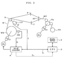
- the display device 10 of the loom may be structured as software installed in a microcomputer 3 and be used for observing and evaluating the behavior of warp W from a warp tension T (Fig. 2).
- a load cell LD which detects the warp tension T for a let-off controller 4 is used as the sensor 1.
- the warp W is pulled out from a warp beam WB via a tension roller R1, and a shed is formed by healds F and F. Then, a weft yarn (not shown) is woven in by being beaten with a reed RF, and a woven fabric WF is obtained accordingly.
- the woven fabric WF is wound around a cloth beam FB via a take-up roller R2.
- a let-off motor Ma is connected to the warp beam WB with a gear box G1 disposed therebetween, and a take-up motor Mb is connected to the cloth beam FB via a gear box G2 disposed therebetween.
- the let-off controller 4 detects the warp tension T on the tension roller R1 with the load cell LD and a beam diameter D of the warp beam WB with a beam-diameter sensor DD, and rotates the warp beam WB while maintaining the warp tension T at a desired value by controlling the speed of the let-off motor Ma.
- the let-off controller 4 executes sampling control using the microcomputer 3, and a sampling period of the warp tension T and the beam diameter D is set to, for example, 20° in terms of crank angle.
- the let-off controller 4 outputs the average value Ta of the warp tension T to the microcomputer 3.
- the memory controller 14 If the external store command Ss is generated (solid arrow in Fig. 3), the memory controller 14 outputs a command to the memory 12 at the time when the crank angle ⁇ reaches 0° immediately after so that the data in the memory area Mo is transmitted and stored in another memory area M1 in the memory 12.
- a storage period is set the same as the memory period, that is, to the length corresponding to seven cycles, and a period shorter than one cycle is not included.
- the memory controller 14 may also store data corresponding to seven cycles excluding a period shorter than one cycle immediately after the generation of the store command Ss (dashed arrow in Fig. 3) in the memory area M1.
- the size of the memory area Mo in the memory controller 14 may be increased such that the memory period is longer than the storage period by at least one cycle, and when the store command Ss is generated, data within the storage period excluding a period shorter than one cycle immediately before the generation of the store command Ss may be instantaneously transmitted to the memory area M1 from the memory area Mo.
- the display controller 13 reads out data in the memory area Mo in the memory 12 and displays a waveform corresponding to the latest data on the screen of the display 2 (Fig. 5).
- the horizontal axis shows the crank angle ⁇ and the vertical axis shows the warp tension T.
- the screen shows, for example, a waveform of the warp tension T corresponding to five previous cycles up to the present in real time.
- two store buttons B1 and B2 are provided so that the store command Ss can be generated twice.
- buttons B3 and B4 are provided for switching the display contents between the data in the memory area Mo and the data in the memory area Mn
- buttons B5 and B6 are provided for switching the value to be displayed between the warp tension T and the average value Ta thereof.
- the waveform shown in Fig. 5 corresponds to the case in which the buttons B3 and B5 are pressed.
- the display controller 13 When the button B4 is pressed, the display command Sd is generated. Accordingly, the display controller 13 reads out data obtained in different memory periods stored in the memory areas M1 and M2, and superimposes them on the screen (Fig. 6). In Fig. 6, waveforms (1) and (2) correspond to data stored in memory areas M1 and M2, respectively. At this time, the store buttons B1 and B2 are changed to shift buttons B1a and B2a, respectively, on the screen. When the buttons B1a and B2a are pressed, a shift command Sf is generated. Accordingly, the display controller 13 shifts the display ranges of the waveforms (1) and (2) corresponding to the memory areas M1 and M2 in the horizontal direction individually (see (1) to (3) in Fig. 3). More specifically, the display range on the screen, which corresponds to five cycles, is set shorter than the storage period in the memory areas M1 and M2, which corresponds to seven cycles.
- the store command Ss is generated by the two store buttons B1 and B2. Accordingly, only the memory areas M1 and M2 corresponding to the buttons B1 and B2, respectively, are necessary.
- the buttons B1 and B2 are pressed multiple times, the contents in the corresponding memory area M1 or M2 are updated by the data in the memory area Mo each time the button is pressed.
- the display controller 13 displays a graph showing the temporal variation in the warp tension up to the present time on the screen using the data of the average value Ta of the warp tension T, which is stored separately. At this time, the display range preferably covers data corresponding to several hundred cycles so that tendency of long-term variation in the warp tension T can be observed.
- a display screen shown in Fig. 7, for example, is obtained.
- the horizontal axis shows the crank angle ⁇ , and the display range is shorter than one cycle.
- the vertical axis shows the signal level of the output signal S1 from the weft feeler.
- waveforms (1) and (2) respectively show a normal operational state and a state in which the variation in the signal level of the output signal S1 is abnormal.
- reference information including the time and date indicating the display period, the rotational speed of the loom, the shedding pattern of the healds F and F, and the kind of the inserted weft at that time may also be memorized and be additionally displayed on the screen.
- the reference information may also be set such that whether or not to display the reference information can be selected.
- the memory controller 14 may also be omitted and both of the crank angle signal Sc and the store command Ss may be input to the sampling unit 11 (Fig. 8).
- the sampling unit 11 samples an output signal S1 from a sensor 1 at every predetermined crank angle ⁇ over a predetermined memory period in response to the store command Ss, and stores the obtained data in the memory areas Mn.
- a display controller 13 superimposes waveforms corresponding to the data obtained in different memory periods and stored in the memory areas Mn of the memory 12 on a screen of the display 2.
Landscapes
- Engineering & Computer Science (AREA)
- Textile Engineering (AREA)
- Health & Medical Sciences (AREA)
- Rehabilitation Therapy (AREA)
- Epidemiology (AREA)
- Pain & Pain Management (AREA)
- Physical Education & Sports Medicine (AREA)
- Life Sciences & Earth Sciences (AREA)
- Animal Behavior & Ethology (AREA)
- General Health & Medical Sciences (AREA)
- Public Health (AREA)
- Veterinary Medicine (AREA)
- Looms (AREA)
Applications Claiming Priority (2)
| Application Number | Priority Date | Filing Date | Title |
|---|---|---|---|
| JP2004156100A JP2005336643A (ja) | 2004-05-26 | 2004-05-26 | 織機の表示方法と、その装置 |
| JP2004156100 | 2004-05-26 |
Publications (4)
| Publication Number | Publication Date |
|---|---|
| EP1600539A2 true EP1600539A2 (fr) | 2005-11-30 |
| EP1600539A9 EP1600539A9 (fr) | 2011-07-13 |
| EP1600539A3 EP1600539A3 (fr) | 2011-12-07 |
| EP1600539B1 EP1600539B1 (fr) | 2014-05-21 |
Family
ID=34935671
Family Applications (1)
| Application Number | Title | Priority Date | Filing Date |
|---|---|---|---|
| EP05008994.5A Expired - Lifetime EP1600539B1 (fr) | 2004-05-26 | 2005-04-25 | Procédé et dispositif d'affichage pour métier à tisser |
Country Status (4)
| Country | Link |
|---|---|
| EP (1) | EP1600539B1 (fr) |
| JP (1) | JP2005336643A (fr) |
| KR (1) | KR20060047173A (fr) |
| CN (1) | CN1702214B (fr) |
Cited By (1)
| Publication number | Priority date | Publication date | Assignee | Title |
|---|---|---|---|---|
| EP2772574A1 (fr) * | 2013-02-27 | 2014-09-03 | Tsudakoma Kogyo Kabushiki Kaisha | Dispositif et procédé d'affichage d'informations pour métier à tisser |
Families Citing this family (4)
| Publication number | Priority date | Publication date | Assignee | Title |
|---|---|---|---|---|
| CN102286836B (zh) * | 2010-06-17 | 2015-05-20 | 株式会社丰田自动织机 | 用于分析织机中的编织条件的方法 |
| JP5866809B2 (ja) * | 2011-06-08 | 2016-02-24 | 東芝三菱電機産業システム株式会社 | ドライブ装置の調整装置 |
| CN102517766B (zh) * | 2011-11-14 | 2013-07-03 | 威海英卓自动化技术有限公司 | 一种纺机探纬工作状态的控制显示方法及装置 |
| JP6145017B2 (ja) * | 2013-02-27 | 2017-06-07 | 津田駒工業株式会社 | 水噴射式織機用の緯入れ情報の表示方法および装置 |
Family Cites Families (5)
| Publication number | Priority date | Publication date | Assignee | Title |
|---|---|---|---|---|
| JPH0726288B2 (ja) * | 1986-08-25 | 1995-03-22 | 津田駒工業株式会社 | 織機の異常状態再生方法 |
| JPH076116B2 (ja) * | 1988-02-15 | 1995-01-25 | 東レ株式会社 | 無杼織機の保全管理方法 |
| JPH03161554A (ja) * | 1989-11-15 | 1991-07-11 | Nissan Motor Co Ltd | 流体噴射式織機の緯入れ監視装置 |
| JPH1181094A (ja) * | 1997-09-01 | 1999-03-26 | Toyota Autom Loom Works Ltd | 織機における緯糸検出装置 |
| JP2004084111A (ja) * | 2002-08-26 | 2004-03-18 | Tsudakoma Corp | 織機の情報表示装置 |
-
2004
- 2004-05-26 JP JP2004156100A patent/JP2005336643A/ja active Pending
-
2005
- 2005-04-11 KR KR1020050029964A patent/KR20060047173A/ko not_active Withdrawn
- 2005-04-25 EP EP05008994.5A patent/EP1600539B1/fr not_active Expired - Lifetime
- 2005-04-25 CN CN2005100676886A patent/CN1702214B/zh not_active Expired - Fee Related
Cited By (2)
| Publication number | Priority date | Publication date | Assignee | Title |
|---|---|---|---|---|
| EP2772574A1 (fr) * | 2013-02-27 | 2014-09-03 | Tsudakoma Kogyo Kabushiki Kaisha | Dispositif et procédé d'affichage d'informations pour métier à tisser |
| JP2014194102A (ja) * | 2013-02-27 | 2014-10-09 | Tsudakoma Corp | 織機用の情報表示方法および情報表示装置 |
Also Published As
| Publication number | Publication date |
|---|---|
| CN1702214B (zh) | 2010-12-22 |
| EP1600539A3 (fr) | 2011-12-07 |
| JP2005336643A (ja) | 2005-12-08 |
| EP1600539A9 (fr) | 2011-07-13 |
| KR20060047173A (ko) | 2006-05-18 |
| CN1702214A (zh) | 2005-11-30 |
| EP1600539B1 (fr) | 2014-05-21 |
Similar Documents
| Publication | Publication Date | Title |
|---|---|---|
| CN101503841B (zh) | 织机的引纬状况显示方法及其显示装置 | |
| JP5550822B2 (ja) | 織機の緯入れ状況表示方法 | |
| EP1600539B1 (fr) | Procédé et dispositif d'affichage pour métier à tisser | |
| EP1396562B1 (fr) | Procédé et dispositif d'affichage des défauts de tissage dans les métiers à tisser | |
| JP2010084315A (ja) | 織機の表示方法と、その装置 | |
| JP2013122107A (ja) | 織機の緯入れ状況表示方法 | |
| EP1600538B1 (fr) | Dispositif d'affichage de la condition de l'insertion de la trame | |
| JP5177666B2 (ja) | 織機の緯入れ状況表示方法 | |
| EP2045382A2 (fr) | Procédé d'affichage des informations opérationnelles dans un métier à tisser | |
| EP2053148A2 (fr) | Métier à tisser disposant d'un dispositif de contrôle d'enlèvement/tissage | |
| JP2005336624A (ja) | 織機の設定装置 | |
| EP2772574B1 (fr) | Dispositif et procédé d'affichage d'informations pour métier à tisser | |
| JP3402552B2 (ja) | 織機の稼働情報表示方法 | |
| CN1629378B (zh) | 显示装置 | |
| JP2550757Y2 (ja) | 織機用表示装置 | |
| JPH0333250A (ja) | 織機における条件入力設定システム | |
| JP3038551U (ja) | 織 機 | |
| JP2005273076A (ja) | 織機のスタート制御装置およびスタート制御方法 | |
| JP4718213B2 (ja) | 織機の経糸張力制御方法及び装置 | |
| JPH08284045A (ja) | 織機の織付け方法と装置 | |
| JPH0525753A (ja) | 織機のスキツプフイーラ装置 | |
| JP2005336651A (ja) | エアジェットルームにおける緯入れ部材の作動状態表示方法 | |
| JPH08246299A (ja) | 織機の送出し制御装置 |
Legal Events
| Date | Code | Title | Description |
|---|---|---|---|
| PUAI | Public reference made under article 153(3) epc to a published international application that has entered the european phase |
Free format text: ORIGINAL CODE: 0009012 |
|
| AK | Designated contracting states |
Kind code of ref document: A2 Designated state(s): AT BE BG CH CY CZ DE DK EE ES FI FR GB GR HU IE IS IT LI LT LU MC NL PL PT RO SE SI SK TR |
|
| AX | Request for extension of the european patent |
Extension state: AL BA HR LV MK YU |
|
| PUAL | Search report despatched |
Free format text: ORIGINAL CODE: 0009013 |
|
| AK | Designated contracting states |
Kind code of ref document: A3 Designated state(s): AT BE BG CH CY CZ DE DK EE ES FI FR GB GR HU IE IS IT LI LT LU MC NL PL PT RO SE SI SK TR |
|
| AX | Request for extension of the european patent |
Extension state: AL BA HR LV MK YU |
|
| 17P | Request for examination filed |
Effective date: 20100601 |
|
| AKX | Designation fees paid |
Designated state(s): BE CH DE IT LI |
|
| GRAP | Despatch of communication of intention to grant a patent |
Free format text: ORIGINAL CODE: EPIDOSNIGR1 |
|
| RIC1 | Information provided on ipc code assigned before grant |
Ipc: D03J 1/00 20060101ALI20110324BHEP Ipc: D03D 47/34 20060101AFI20110324BHEP Ipc: D03D 49/06 20060101ALI20110324BHEP |
|
| GRAJ | Information related to disapproval of communication of intention to grant by the applicant or resumption of examination proceedings by the epo deleted |
Free format text: ORIGINAL CODE: EPIDOSDIGR1 |
|
| RIC1 | Information provided on ipc code assigned before grant |
Ipc: D03J 1/00 20060101ALI20110825BHEP Ipc: D03D 47/34 20060101AFI20110825BHEP Ipc: D03D 49/06 20060101ALI20110825BHEP Ipc: D03D 47/30 20060101ALI20110825BHEP |
|
| PUAF | Information related to the publication of a search report (a3 document) modified or deleted |
Free format text: ORIGINAL CODE: 0009199SEPU |
|
| PUAL | Search report despatched |
Free format text: ORIGINAL CODE: 0009013 |
|
| D17D | Deferred search report published (deleted) | ||
| AK | Designated contracting states |
Kind code of ref document: A3 Designated state(s): BE CH DE IT LI |
|
| GRAP | Despatch of communication of intention to grant a patent |
Free format text: ORIGINAL CODE: EPIDOSNIGR1 |
|
| INTG | Intention to grant announced |
Effective date: 20131216 |
|
| GRAS | Grant fee paid |
Free format text: ORIGINAL CODE: EPIDOSNIGR3 |
|
| GRAA | (expected) grant |
Free format text: ORIGINAL CODE: 0009210 |
|
| AK | Designated contracting states |
Kind code of ref document: B1 Designated state(s): BE CH DE IT LI |
|
| REG | Reference to a national code |
Ref country code: CH Ref legal event code: EP |
|
| REG | Reference to a national code |
Ref country code: DE Ref legal event code: R096 Ref document number: 602005043685 Country of ref document: DE Effective date: 20140703 |
|
| REG | Reference to a national code |
Ref country code: DE Ref legal event code: R097 Ref document number: 602005043685 Country of ref document: DE |
|
| PLBE | No opposition filed within time limit |
Free format text: ORIGINAL CODE: 0009261 |
|
| STAA | Information on the status of an ep patent application or granted ep patent |
Free format text: STATUS: NO OPPOSITION FILED WITHIN TIME LIMIT |
|
| 26N | No opposition filed |
Effective date: 20150224 |
|
| REG | Reference to a national code |
Ref country code: DE Ref legal event code: R097 Ref document number: 602005043685 Country of ref document: DE Effective date: 20150224 |
|
| REG | Reference to a national code |
Ref country code: CH Ref legal event code: PL |
|
| PG25 | Lapsed in a contracting state [announced via postgrant information from national office to epo] |
Ref country code: CH Free format text: LAPSE BECAUSE OF NON-PAYMENT OF DUE FEES Effective date: 20150430 Ref country code: LI Free format text: LAPSE BECAUSE OF NON-PAYMENT OF DUE FEES Effective date: 20150430 |
|
| PGFP | Annual fee paid to national office [announced via postgrant information from national office to epo] |
Ref country code: IT Payment date: 20220310 Year of fee payment: 18 Ref country code: BE Payment date: 20220321 Year of fee payment: 18 |
|
| PGFP | Annual fee paid to national office [announced via postgrant information from national office to epo] |
Ref country code: DE Payment date: 20220302 Year of fee payment: 18 |
|
| REG | Reference to a national code |
Ref country code: DE Ref legal event code: R119 Ref document number: 602005043685 Country of ref document: DE |
|
| REG | Reference to a national code |
Ref country code: BE Ref legal event code: MM Effective date: 20230430 |
|
| PG25 | Lapsed in a contracting state [announced via postgrant information from national office to epo] |
Ref country code: DE Free format text: LAPSE BECAUSE OF NON-PAYMENT OF DUE FEES Effective date: 20231103 |
|
| PG25 | Lapsed in a contracting state [announced via postgrant information from national office to epo] |
Ref country code: BE Free format text: LAPSE BECAUSE OF NON-PAYMENT OF DUE FEES Effective date: 20230430 |
|
| PG25 | Lapsed in a contracting state [announced via postgrant information from national office to epo] |
Ref country code: IT Free format text: LAPSE BECAUSE OF NON-PAYMENT OF DUE FEES Effective date: 20230425 |