EP1597188B1 - Klemmvorrichtung für eine einrichtung zur handhabung von elektrolyseelementen bei der produktion von aluminium - Google Patents
Klemmvorrichtung für eine einrichtung zur handhabung von elektrolyseelementen bei der produktion von aluminium Download PDFInfo
- Publication number
- EP1597188B1 EP1597188B1 EP04714818A EP04714818A EP1597188B1 EP 1597188 B1 EP1597188 B1 EP 1597188B1 EP 04714818 A EP04714818 A EP 04714818A EP 04714818 A EP04714818 A EP 04714818A EP 1597188 B1 EP1597188 B1 EP 1597188B1
- Authority
- EP
- European Patent Office
- Prior art keywords
- clamp
- locking
- lock
- stem
- gripping
- Prior art date
- Legal status (The legal status is an assumption and is not a legal conclusion. Google has not performed a legal analysis and makes no representation as to the accuracy of the status listed.)
- Expired - Lifetime
Links
Images



Classifications
-
- B—PERFORMING OPERATIONS; TRANSPORTING
- B66—HOISTING; LIFTING; HAULING
- B66C—CRANES; LOAD-ENGAGING ELEMENTS OR DEVICES FOR CRANES, CAPSTANS, WINCHES, OR TACKLES
- B66C1/00—Load-engaging elements or devices attached to lifting or lowering gear of cranes or adapted for connection therewith for transmitting lifting forces to articles or groups of articles
- B66C1/10—Load-engaging elements or devices attached to lifting or lowering gear of cranes or adapted for connection therewith for transmitting lifting forces to articles or groups of articles by mechanical means
- B66C1/62—Load-engaging elements or devices attached to lifting or lowering gear of cranes or adapted for connection therewith for transmitting lifting forces to articles or groups of articles by mechanical means comprising article-engaging members of a shape complementary to that of the articles to be handled
- B66C1/66—Load-engaging elements or devices attached to lifting or lowering gear of cranes or adapted for connection therewith for transmitting lifting forces to articles or groups of articles by mechanical means comprising article-engaging members of a shape complementary to that of the articles to be handled for engaging holes, recesses, or abutments on articles specially provided for facilitating handling thereof
-
- B—PERFORMING OPERATIONS; TRANSPORTING
- B66—HOISTING; LIFTING; HAULING
- B66C—CRANES; LOAD-ENGAGING ELEMENTS OR DEVICES FOR CRANES, CAPSTANS, WINCHES, OR TACKLES
- B66C1/00—Load-engaging elements or devices attached to lifting or lowering gear of cranes or adapted for connection therewith for transmitting lifting forces to articles or groups of articles
- B66C1/10—Load-engaging elements or devices attached to lifting or lowering gear of cranes or adapted for connection therewith for transmitting lifting forces to articles or groups of articles by mechanical means
- B66C1/62—Load-engaging elements or devices attached to lifting or lowering gear of cranes or adapted for connection therewith for transmitting lifting forces to articles or groups of articles by mechanical means comprising article-engaging members of a shape complementary to that of the articles to be handled
-
- C—CHEMISTRY; METALLURGY
- C25—ELECTROLYTIC OR ELECTROPHORETIC PROCESSES; APPARATUS THEREFOR
- C25C—PROCESSES FOR THE ELECTROLYTIC PRODUCTION, RECOVERY OR REFINING OF METALS; APPARATUS THEREFOR
- C25C3/00—Electrolytic production, recovery or refining of metals by electrolysis of melts
- C25C3/06—Electrolytic production, recovery or refining of metals by electrolysis of melts of aluminium
- C25C3/08—Cell construction, e.g. bottoms, walls, cathodes
- C25C3/10—External supporting frames or structures
Definitions
- the invention relates to aluminum production plants by igneous electrolysis according to the Hall-Héroult process. It relates more particularly handling equipment used in said factories.
- Aluminum metal is produced industrially by igneous electrolysis, namely by electrolysis of alumina in solution in a bath of molten cryolite, called electrolyte bath, according to the well-known Hall-Héroult process.
- the electrolyte bath is contained in tanks, called “electrolysis cells”, comprising a steel box, which is coated internally with refractory and / or insulating materials, and a cathode assembly located at the bottom of the tank.
- Anodes typically of carbonaceous material, are partially immersed in the electrolyte bath.
- the assembly formed by an electrolytic cell, its anodes and the electrolyte bath is called an electrolysis cell.
- the plants contain a large number of electrolysis cells arranged in line, in buildings called halls or electrolysis rooms, and connected electrically in series using connecting conductors, so as to optimize the ground occupation of the cells. factories.
- the cells are generally arranged to form two or more parallel lines that are electrically bonded together by end conductors. The electrolysis current thus cascades from one cell to the next.
- an electrolysis plant requires interventions on the electrolysis cells including among others the replacement of spent anodes by new anodes, the removal of liquid metal from the cells and the removal or addition of electrolyte.
- the most modern factories are equipped with a lifting and handling unit with a traveling crane, which can be moved over and along the electrolysis cells, and a truck equipped with several handling devices. and intervention (often called "tools"), such as shovels and hoists.
- the handling member which is intended for handling and moving loads such as anodes comprises a gripper capable of grasping the load, called “handling tongs". For example, during anode handling operations, this clamp is placed near the stem of the anode to be seized, and then closed on the rod sufficiently to lift the anode. The anode is then moved, then positioned or deposited at the desired location.
- a handling gripper according to the preamble of independent claim 1 is known from FR-A-1363432 for handling fuel assemblies of nuclear reactors.
- the subject of the invention is a handling gripper intended for the aluminum production industry by igneous electrolysis, capable of gripping a load by a gripping member (hereinafter called a "rod") fixed to said load, and having locking means adapted to prohibit the opening of the clamp when the load is suspended by it.
- a gripping member hereinafter called a "rod”
- the handling gripper according to the invention which is intended to grip a load provided with a rod, comprises the features of claim 1.
- the Applicant had the idea to provide the clamp with a locking system which is locked or unlocked by the only movement of the rod in the clamp.
- the locking system blocks the gripping member (s) in the closed position, thereby preventing the opening of the clamp and the release of the rod.
- the locking is controlled by the presence and position of the rod in the clamp, which prevents untimely falls of the load in the event of failure of the actuating means of the movable or gripping members of the clamp.
- the subject of the invention is also the use of the handling tongs according to the invention in an igneous electrolysis aluminum production plant, in particular for the handling of anodes made of carbonaceous material or the like.
- the invention further relates to a lifting and handling unit comprising at least one load handling member (typically anodes) provided with a handling tongs according to the invention.
- load handling member typically anodes
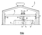
- the figure 1 illustrates a typical electrolysis room, seen in section, intended for the production of aluminum.
- the figure 2 illustrates, in profile, a handling tongs according to the invention.
- the figure 3 illustrates, in profile, the movable elements of a handling gripper according to the invention.
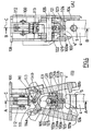
- the figure 4 illustrates a handling tongs according to the invention, seen in longitudinal section along two perpendicular planes (planes AA and BB).
- the figure 5 illustrates the operation of the locking system of the handling gripper according to the invention with the aid of a particular example.
- Electrolysis plants for aluminum production include a liquid aluminum production zone that includes one or more electrolysis rooms (1).
- each electrolysis room (1) comprises electrolysis cells (2) and at least one lifting and handling unit, or "service machine", (6, 7, 8, 9, 10).
- the electrolysis cells (2) are normally arranged in rows or rows (typically side-by-side or head-to-head), each row or line typically having one or more hundreds of cells.
- the cells (2) comprise a series of anodes (3) provided with a metal rod (4) for fixing and electrically connecting the anodes to a metal anode frame (not shown).
- the anode rod (4) is typically of substantially rectangular or square section.
- the lifting and handling unit (6, 7, 8, 9, 10) is used to perform operations on the cells such as anode change or filling of ground bath feed hoppers and ALF 3 electrolysis cells. It can also be used to handle various loads, such as tank elements, pockets of liquid metal or anodes.
- Said unit (6, 7, 8, 9, 10) typically comprises a crane (6), a carriage (7) adapted to move on the crane (6), and handling and intervention members (often referred to as "tools") (8, 9, 10), such as an operator's cabin (8), a shovel or crust (not illustrated), a breaker (not shown) or a handling member (9) provided with a gripper or handling gripper (10).
- tools often referred to as "tools”
- the latter is particularly intended for handling anodes (3), although it can also be used for handling other loads.
- the crane (6) rests and circulates on raceways (11, 12) arranged parallel to each other and to the main - and typically longitudinal - axis of the hall (and the queue of cells). The crane (6) can thus be moved along the electrolysis room (1).
- the or the gripping members release sufficient space to allow the insertion of the rod into the clamp.
- the or each gripping member (100a, 100b) is advantageously pivotable about an axis (105).
- the clamp (10) typically comprises two gripping members (100a, 100b), which are advantageously pivotable about an axis (105) specific to each gripping member or common to both gripping members.
- the clamp (10) is then typically symmetrical about an axis C, called "central axis", which may coincide with the axis of the rod (4).
- the axis or axes (105) are preferably substantially perpendicular to the axis C, so as to be substantially horizontal in use.
- the connecting means (101a, 101b) of the clamp (10) typically comprise a projection on the or each gripping member (100a, 100b) and the corresponding connecting means (5, 5a, 5b) of the rod ( 4) comprise at least one cavity.
- the or projections (101a, 101b) of the or each gripping member (100a, 100b) are adapted to cooperate with the corresponding cavity or cavities (5, 5a, 5b) of the rod (4) so as to limit the displacements axial axis of the rod (4) between said low and high positions when the or each gripping member (100a, 100b) is in the closed position.
- the dimensions of the connecting means (101a, 101b, 5, 5a, 5b) are such that, when they are engaged, the rod (4) can be further moved between the upper position, in which the locking system (120) is unlocked (as shown in Figure 5 (E) ), and the low position, in which the locking system (120) is locked (as illustrated in FIG. Figure 5 (F) ).
- This can be achieved by arranging one or more cavities (5, 5a, 5b) with enough clearance to allow these displacements.
- connection means (101a, 101b) of the clamp (10) and the corresponding connecting means (5, 5a, 5b) of the rod (4) are advantageously such that they substantially limit - and possibly prevent - the rotation of the rod (4) about its axis A, which ensures accurate positioning of the load attached to the rod, usually an anode.
- the clamp further comprises a clamp body (109) and a fastening means (108).
- the latter allows in particular to fix the clamp (10) to a handling member (9).
- the locking system (120) of the clamp (10) is locked (or “engaged") when, at the same time, the one or more gripping members (100a, 100b) are in the closed position and the rod (4) is in the down position, which typically occurs when the load is suspended by the clamp (10), and is unlocked when the rod (4) is in the up position, which typically occurs when the clamp ( 10) exerts a push on the rod (4).
- the clamp (10) according to the invention thus allows locking or unlocking said locking system (120) by a simple relative movement of the rod (4) relative to the clamp (and typically in the clamp).
- the locking position of the lock (121) is typically a low position and the unlocking position is typically a high position, which is which allows locking of the locking system (120) by the effect of gravity.
- the lock (121) is advantageously able to be moved along a central axis of symmetry C of the clamp (10).
- the latch (121) is typically provided with at least one cavity (126a, 126b), such as a notch or a mortise, adapted to cooperate with the or each locking element (102a, 102b) so as to prevent the movement of the or each gripping member (100a, 100b) from the closed position to the open position.
- the latch (121) has a standby position - which is typically said lock position but which may be different from it - and is located in the clamp so that the rod (4) can move from the standby position to the unlock position when it is inserted into the clamp.
- the lock (121) may comprise a pushing member (124), such as a pin, and is adapted to be moved from the waiting position to said unlocking position by a thrust of the rod (4). ) - and more precisely the end (4 ') of the rod (4) - on said thrust member (124).
- Said pushing member (124) is typically located near the end (127) of the latch (121) located on the side of the opening of the clamp.
- the clamp (10) may further comprise at least one guide piece (122, 123) adapted to guide the movement of the latch (121) during its movements between its different positions.
- the clamp (10) comprises a first guide piece (122) able to slide inside the lock (121) and a second guide piece (123) able to guide the "low" end (127) of the lock (121).
- the first guide piece (122) is typically attached to a ball or a transverse or axial axis.
- the second guide piece (123) also acts as a stop.
- the locking system (120) further comprises at least one biasing means, such as an elastic member, (125) adapted to cause the lock (121) to move from the unlocking position to the locking position, and able to hold it in the latter position, when the or each gripping member (100a, 100b) is in the closed position and the rod (4) is in the down position.
- the return means (125) which is typically a spring, is advantageously integrated in the lock (121) in order to isolate it from the environment and, possibly, to lubricate it, in order to maintain its elasticity and to avoid its deterioration.
- the return means (125) is advantageously located in a recess inside the lock (121) and / or in a recess inside a guide piece (122) of the lock.
- the return means (125) is located partly in a recess inside the latch (121) and partly in a recess inside a guide piece (122) of the latch.
- the locking system (120) further comprises at least one means, called locking, adapted to maintain the or each gripping member (100a, 100b) in the open position when the lock (121 ) is in the locked or standby position, as illustrated in Figures 5 (B) , 4 (B) and 4 (C).
- These locking means make it possible to mechanically prohibit the closing of the clamp when the rod is not placed correctly therein, in particular when the rod is not placed in the clamp so as to allow the engagement of the means of link (101a, 101b, 5, 5a, 5b) between the rod and the clamp.
- Said locking means are advantageously formed by the latch (121) and the locking elements (102a, 102b) which are then such that said elements rest on the latch when it is in the waiting position (typically the position locking), so as to prohibit the closure of the or gripping members.
- the clamp (10) may further comprise one or more guide pieces (103, 104) of the rod (4) to ensure a satisfactory positioning thereof between the gripping members (100a, 100b) of the clamp.
- the depression of the rod (4) in the clamp may optionally be limited by a stop (123).
- the gripping members (100a, 100b) and / or the guide piece (s) (103, 104) preferably define a cavity which matches the shape of the shank so as to limit or even prevent rotation thereof.
- the grippers (100a, 100b) of the gripper can be actuated by various means.
- the figures 3 and 4 illustrate a clamp (10) in which the actuating system (110) comprises two connecting rods (114a, 114b) and an actuator (112), which is typically a jack.
- the actuator (112) and the connecting rods (114a, 114b) are typically connected by a common actuating pin (113) attached to the actuator rod (111) of the actuator.
- This variant has the advantage of being simple, reliable and effective.
- the gripper according to the invention advantageously comprises two movable gripping members (100a, 100b) and the lock (121) is preferably between these two gripping members. This configuration allows a compact construction and protects the shock lock with external elements.
- the locking system (120) is preferably entirely mechanical, such as that illustrated in FIGS. Figures 3 to 5 , in order to avoid failure modes related to electrical or electromechanical elements.
- the gripping members (100a, 100b) are pivotable freely about their respective (or common) axis (105) and allow, in particular, positioning of the locking element or elements (102a, 102b) in front of each cavity ( 126a, 126b) and engagement of the connecting means (101a, 101b, 5, 5a, 5b), typically by introducing the projections (101a, 101b) into the corresponding cavities (5, 5a, 5b) of the rod (4).
- the grippers (100a, 100b) are locked when the gripper (10) is pulled up and the rod (4) descends under the effect of its own weight and that of the load ( Figure 5 (E) ).
- the descent of the rod (4) is stopped by the connecting means (101a, 101b, 5, 5a, 5b).
- the one or more locking elements (102a, 102b) are inserted into the corresponding cavity (s) (126a, 126b) and cooperate with the latter to prevent the opening of the latches (126a, 126b).
- gripping members (100a, 100b) of the gripper (10) ( Figure 5 (F) ).
- the lock is effective as long as the load is suspended.
- the locking system is unlocked by raising the rod in the clamp, which is typically achieved by pressing the load.
- Such a system has the advantage of not requiring additional actuators and thus increase the reliability of the device. It also has the advantage of providing a locking action regardless of the weight of the load and the friction force between the connecting means (101a, 101b, 5, 5a, 5b).
- the latch (121) has a waiting position ( Figures 5 (A) and 5 (B) ) which merges with the locking position ( Figure 5 (F) ).
- the locking elements (102a, 102b) cooperate with the latch (121), relying on the latter, so as to prohibit the closure of the clamp as the rod (4) is not sufficient depressed to allow alignment of the projections (101a, 101b) and cavities (5, 5a, 5b).
- the locking elements (102a, 102b) cooperate with the latch (121) by a camming effect.
- the invention also relates to a lifting and handling unit (6, 7, 8, 9, 10) comprising at least one load-handling member (such as anodes) (9) provided with a handling tongs (10) according to the invention.
- a lifting and handling unit (6, 7, 8, 9, 10) comprising at least one load-handling member (such as anodes) (9) provided with a handling tongs (10) according to the invention.
- the invention avoids dual-control systems. It also has the advantage of being virtually insensitive to acceleration during handling.
Landscapes
- Engineering & Computer Science (AREA)
- Chemical & Material Sciences (AREA)
- Mechanical Engineering (AREA)
- Organic Chemistry (AREA)
- Materials Engineering (AREA)
- Metallurgy (AREA)
- Electrochemistry (AREA)
- Chemical Kinetics & Catalysis (AREA)
- Load-Engaging Elements For Cranes (AREA)
- Electrolytic Production Of Metals (AREA)
- Clamps And Clips (AREA)
- Manipulator (AREA)
- Electrolytic Production Of Non-Metals, Compounds, Apparatuses Therefor (AREA)
- Gripping Jigs, Holding Jigs, And Positioning Jigs (AREA)
Claims (23)
- Handhabungszange (10) zum Greifen einer Stange (4), welche an einer Last (3) befestigt und mit mindestens einem Verbindungsmittel (5, 5a, 5b) versehen ist, umfassend:- mindestens ein bewegliches Greiforgan (100a, 100b), typischerweise eine Backe, mit einer offenen Stellung, die eine im Gebrauch typischerweise nach unten gerichtete Öffnung bildet, in welche die Stange (4) eingeführt werden kann, und einer geschlossenen Stellung zum Festhalten der Stange (4),- ein Betätigungssystem (110), um das bzw. jedes Greiforgan (100a, 100b) zwischen der offenen und der geschlossenen Stellung zu bewegen,- mindestens ein Verbindungsmittel (101a, 101b), das geeignet ist, mit dem bzw. den entsprechenden Verbindungsmitteln (5, 5a, 5b) der Stange (4) zusammenzuwirken, um die Axialverschiebungen der Stange (4) in der Zange (10) zwischen einer sog. tiefen Stellung und einer sog. hohen Stellung zu begrenzen, wenn sich das bzw. jedes Greiforgan (100a, 100a) in der geschlossenen Stellung befindet,- mindestens ein Verriegelungssystem (120), das geeignet ist, das bzw. jedes Greiforgan (100a, 100b) in der geschlossenen Stellung zu blockieren, wenn es verriegelt ist, und das verriegelbar ist, wenn sich die Stange (4) in der tiefen Stellung befindet, und entriegelbar ist, wenn sich die Stange (4) in der hohen Stellung befindet,dadurch gekennzeichnet, dass das Verriegelungssystem (120) mindestens ein an jedem Greiforgan (100a, 100b) befestigtes Verriegelungselement (102a, 102b), wie z.B. einen Zahn oder Haken, und mindestens einen beweglichen Riegel (121) mit einer ersten, sog. Verriegelungsstellung und einer zweiten, sog. Entriegelungsstellung umfasst, wobei der Riegel (121) von der Entriegelungsstellung in die Verriegelungsstellung bewegbar ist, wenn sich das bzw. jedes Greiforgan (100a, 100b) in der geschlossenen Stellung befindet und die Stange (4) sich in der tiefen Stellung befindet, mit dem bzw. jedem Verriegelungselement (102a, 102b) zusammenwirken kann, um die Bewegung des bzw. jedes Greiforgans (100a, 100b) zu gestatten, wenn er sich in der Entriegelungsstellung befindet, und das bzw. jedes Greiforgan (100a, 100b) in der geschlossenen Stellung zu halten, wenn er sich in der Verriegelungsstellung befindet, und durch eine Axialverschiebung der Stange (4) von der tiefen Stellung in die hohe Stellung von der Verriegelungsstellung in die Entriegelungsstellung bewegbar ist.
- Zange (10) nach Anspruch 1, dadurch gekennzeichnet, dass das bzw. jedes Greiforgan (100a, 100b) um eine Achse (105) verschwenkbar ist.
- Zange (10) nach irgendeinem der Ansprüche 1 oder 2, dadurch gekennzeichnet, dass sie zwei Greiforgane (100a, 100b) umfasst.
- Zange (10) nach Anspruch 3, dadurch gekennzeichnet, dass die beiden Greiforgane (100a, 100b) um jeweils eine eigene oder für die beiden Greiforgane gemeinsame Achse (105) verschwenkbar sind.
- Zange (10) nach irgendeinem der Ansprüche 1 bis 4, dadurch gekennzeichnet, dass die Verbindungsmittel (101 a, 101 b) der Zange (10) mindestens einen Vorsprung an dem bzw. jedem Greiforgan (100a, 100b) aufweisen und dass die entsprechenden Verbindungsmittel (5, 5a, 5b) der Stange (4) mindestens eine Vertiefung aufweisen.
- Zange (10) nach irgendeinem der Ansprüche 1 bis 5, dadurch gekennzeichnet, dass die Verriegelungsstellung des Riegels (121) im Gebrauch eine tiefe Stellung und die Entriegelungsstellung eine hohe Stellung ist.
- Zange (10) nach irgendeinem der Ansprüche 1 bis 6, dadurch gekennzeichnet, dass der Riegel (121) mit mindestens einer Vertiefung (126a, 126b) versehen ist, die geeignet ist, mit dem bzw. jedem Verriegelungselement (102a, 102b) zusammenzuwirken, um die Bewegung des bzw. jedes Greiforgans (100a, 100b) von der geschlossenen Stellung in die offene Stellung zu unterbinden.
- Zange (10) nach irgendeinem der Ansprüche 1 bis 7, dadurch gekennzeichnet, dass der Riegel (121) eine Wartestellung besitzt und so in der Zange gelegen ist, dass die Stange (4) ihn bei ihrer Einführung in die Zange von der Wartestellung in die Entriegelungsstellung bewegen kann.
- Zange (10) nach Anspruch 8, dadurch gekennzeichnet, dass die Wartestellung der Verriegelungsstellung entspricht.
- Zange (10) nach irgendeinem der Ansprüche 8 bis 9, dadurch gekennzeichnet, dass der Riegel (121) ein Schubglied (124) umfasst, z. B. einen Zapfen, und durch eine Schubwirkung der Stange (4) auf das Schubglied (124) von der Wartestellung in die Entriegelungsstellung bewegbar ist.
- Zange (10) nach Anspruch 10, dadurch gekennzeichnet, dass sich das Schubglied (124) in der Nähe des auf der Öffnungsseite der Zange liegenden Endes (127) des Riegels (121) befindet.
- Zange (10) nach irgendeinem der Ansprüche 1 bis 11, dadurch gekennzeichnet, dass sie zudem mindestens ein Führungsteil (122, 123) umfasst, das geeignet ist, die Bewegung des Riegels (121) bei seinen Bewegungen zwischen den verschiedenen Stellungen zu führen.
- Zange (10) nach irgendeinem der Ansprüche 1 bis 12, dadurch gekennzeichnet, dass das Verriegelungssystem (120) zudem mindestens ein Rückstellmittel (125) umfasst, das geeignet ist, die Bewegung des Riegels (121) von der Entriegelungsstellung in die Verriegelungsstellung herbeizuführen und ihn in der letztgenannten Stellung zu halten, wenn sich das bzw. jedes Greiforgan (100a, 100b) in der geschlossenen Stellung befindet und die Stange (4) sich in der tiefen Stellung befindet.
- Zange (10) nach Anspruch 13, dadurch gekennzeichnet, dass das Rückstellmittel (125) ein elastisches Mittel ist, z.B. eine Feder.
- Zange (10) nach irgendeinem der Ansprüche 13 oder 14, dadurch gekennzeichnet, dass ein Rückstellmittel (125) in einer Ausnehmung innerhalb des Riegels (121) und/oder in einer Ausnehmung innerhalb des Führungsteils (122) liegt.
- Zange (10) nach irgendeinem der Ansprüche 13 bis 14, dadurch gekennzeichnet, dass ein Rückstellmittel (125) zum Teil in einer Ausnehmung innerhalb des Riegels (121) und zum Teil in einer Ausnehmung innerhalb eines Führungsteils (122) liegt.
- Zange (10) nach irgendeinem der Ansprüche 1 bis 16, dadurch gekennzeichnet, dass das Verriegelungssystem (120) zudem mindestens ein sog. Blockiermittel umfasst, das geeignet ist, das bzw. jedes Greiforgan (100a, 100b) in der offenen Stellung zu halten, wenn sich der Riegel (121) in der Verriegelungsstellung oder in der Wartestellung befindet.
- Zange (10) nach irgendeinem der Ansprüche 1 bis 17, dadurch gekennzeichnet, dass sie zwei bewegliche Greiforgane (100a, 100b) umfasst und dass der Riegel (121) zwischen diesen beiden Greiforganen liegt.
- Zange (10) nach irgendeinem der Ansprüche 1 bis 18, dadurch gekennzeichnet, dass das Betätigungssystem (110) aus zwei Pleueln (114a, 114b) und einem Stellglied (112) besteht und dass das Stellglied (112) und die Pleuel (114a, 114b) durch eine gemeinsame Betätigungsachse (113) verbunden sind, die an der Betätigungsstange (111) des Stellglieds befestigt ist.
- Zange (10) nach Anspruch 19, dadurch gekennzeichnet, dass das Stellglied (112) ein Zylinder ist.
- Zange (10) nach irgendeinem der Ansprüche 1 bis 20, dadurch gekennzeichnet, dass das Verriegelungssystem (120) voll mechanisch ist.
- Hebe- und Handhabungseinheit (6, 7, 8, 9, 10), umfassend mindestens ein Handhabungsorgan (9) für Lasten (3), welches mit einer Handhabungszange (10) nach irgendeinem der Ansprüche 1 bis 21 versehen ist.
- Verwendung der Handhabungszange (10) nach irgendeinem der Ansprüche 1 bis 21 in einem Werk zur Herstellung von Aluminium durch Schmelzflusselektrolyse, insbesondere für die Handhabung von Anoden aus kohlenstoffhaltigem Werkstoff oder dgl.
Applications Claiming Priority (3)
| Application Number | Priority Date | Filing Date | Title |
|---|---|---|---|
| FR0302500A FR2851762B1 (fr) | 2003-02-28 | 2003-02-28 | Pince de manutention d'une machine de service de cellules d'electrolyse pour la production d'alumunium |
| FR0302500 | 2003-02-28 | ||
| PCT/FR2004/000430 WO2004079046A2 (fr) | 2003-02-28 | 2004-02-26 | Pince de manutention d'une machine de service de cellules d'electrolyse pour la production d'aluminium |
Publications (2)
| Publication Number | Publication Date |
|---|---|
| EP1597188A2 EP1597188A2 (de) | 2005-11-23 |
| EP1597188B1 true EP1597188B1 (de) | 2008-09-10 |
Family
ID=32843084
Family Applications (1)
| Application Number | Title | Priority Date | Filing Date |
|---|---|---|---|
| EP04714818A Expired - Lifetime EP1597188B1 (de) | 2003-02-28 | 2004-02-26 | Klemmvorrichtung für eine einrichtung zur handhabung von elektrolyseelementen bei der produktion von aluminium |
Country Status (14)
| Country | Link |
|---|---|
| US (1) | US7850218B2 (de) |
| EP (1) | EP1597188B1 (de) |
| CN (1) | CN100377985C (de) |
| AR (1) | AR043215A1 (de) |
| AT (1) | ATE407907T1 (de) |
| AU (1) | AU2004217777B2 (de) |
| BR (1) | BRPI0407884A (de) |
| CA (1) | CA2517267C (de) |
| DE (1) | DE602004016465D1 (de) |
| EA (1) | EA007259B1 (de) |
| FR (1) | FR2851762B1 (de) |
| IS (1) | IS7989A (de) |
| WO (1) | WO2004079046A2 (de) |
| ZA (1) | ZA200506334B (de) |
Cited By (1)
| Publication number | Priority date | Publication date | Assignee | Title |
|---|---|---|---|---|
| EP4223910A1 (de) | 2022-02-04 | 2023-08-09 | Reel GmbH | Anodenzange, fördersystem und verfahren zum beladen eines anodenstabes |
Families Citing this family (36)
| Publication number | Priority date | Publication date | Assignee | Title |
|---|---|---|---|---|
| FR2884833B1 (fr) * | 2005-04-20 | 2007-05-25 | Ecl Soc Par Actions Simplifiee | Dispositif et procede de maintien et de raccordement d'une tige d'anode sur un cadre anodique d'une cellule d'electrolise de l'aluminium |
| FR2913985B1 (fr) * | 2007-03-23 | 2009-08-28 | Ecl Soc Par Actions Simplifiee | Module de service muni d'au moins une pince a anode et d'un moyen permettant d'exercer une force ou un choc sur la tige d'anode. |
| US8414042B2 (en) * | 2007-10-15 | 2013-04-09 | Delaware Capital Formation, Inc. | Articulating package palletizing system |
| CN101633477B (zh) * | 2008-07-23 | 2011-11-16 | 沈阳铝镁设计研究院有限公司 | 设置在电解铝厂检修通道处的轨道提升机组 |
| FR2937341B1 (fr) * | 2008-10-16 | 2010-11-12 | Ecl | Machine de service utilisee pour intervenir sur les cellules d'electrolyse de production d'aluminium par electrolyse ignee |
| JP5489874B2 (ja) * | 2010-06-17 | 2014-05-14 | セイコーインスツル株式会社 | 把持装置 |
| EP2614178B1 (de) * | 2010-09-08 | 2017-04-05 | Fives Ecl | Handhabungswerkzeug zur sicheren handhabung von verbindern für elektrolysezellen zur herstellung von aluminium |
| CN102153014B (zh) * | 2011-04-15 | 2013-05-08 | 张树文 | 用于长型材吊装自动机械手的吊钩涨合控制器 |
| CN102586807B (zh) * | 2012-02-27 | 2015-07-15 | 福建省南平铝业有限公司 | 一种阳极夹持机构 |
| CN102825376B (zh) * | 2012-08-12 | 2015-04-15 | 温州天基机器人自动化有限公司 | 推杆夹具组 |
| CN102978668B (zh) * | 2012-12-20 | 2016-03-02 | 株洲天桥起重机股份有限公司 | 电解阴阳极板的吊运方法及其吊具 |
| CN103862481B (zh) * | 2014-03-27 | 2016-02-10 | 江苏莘翔机电有限公司 | 一种机械手夹持装置 |
| CN103894718B (zh) * | 2014-03-31 | 2016-08-24 | 浙江欣通电气有限公司 | 银点点焊机的夹具组件 |
| CN104588525B (zh) * | 2014-11-27 | 2017-05-17 | 丹阳正联知识产权运营管理有限公司 | 一种液压阀底板多向打孔成型装置的抓料机构 |
| CN104525701B (zh) * | 2014-11-27 | 2017-05-10 | 丹阳正联知识产权运营管理有限公司 | 一种液压阀底板连续成型加工系列的多向打孔成型装置 |
| CN104440933B (zh) * | 2014-11-28 | 2016-06-08 | 上海梓威自动化科技有限公司 | 一种可回转式自动抓瓶机械手 |
| CN104669288B (zh) * | 2015-02-03 | 2018-11-13 | 徐州德坤电气科技有限公司 | 一种翅片总成小u形管无序自动抓管插管机械手 |
| CN104669253B (zh) * | 2015-02-03 | 2018-11-13 | 徐州德坤电气科技有限公司 | 一种基于数字总线的翅片总成小u形管抓取插管机械手 |
| NO343337B1 (en) * | 2017-05-29 | 2019-02-04 | Norsk Hydro As | Device for gripping an anode for lifting operations and method for operating same |
| CN107601024A (zh) * | 2017-08-15 | 2018-01-19 | 吴杉镐 | 一种金属件抓取装置 |
| US10654176B2 (en) | 2017-10-31 | 2020-05-19 | Amazon Technologies, Inc. | Finger assembly having a talon and barrel cam actuation |
| US10800045B1 (en) * | 2017-10-31 | 2020-10-13 | Amazon Technologies, Inc. | Finger assembly having a spring-biased talon |
| US10702994B1 (en) | 2017-10-31 | 2020-07-07 | Amazon Technologies, Inc. | Finger assembly having a talon and spin paddle actuation |
| US10118299B1 (en) * | 2018-02-23 | 2018-11-06 | Yak Mat, LLC. | Rod puller |
| CN109171111B (zh) * | 2018-08-07 | 2021-04-23 | 武汉理惠诚机器人科技有限公司 | 一种用于鞋坯冷热模处理的自动下料装置 |
| US10787259B2 (en) * | 2018-11-08 | 2020-09-29 | Colorado State University Research Foundation | Compliant bistable gripper for aerial perching and grasping |
| JP6940472B2 (ja) * | 2018-11-16 | 2021-09-29 | ファナック株式会社 | ワーク把持ハンド、ハンドシステム、及びロボットシステム |
| FR3093737B1 (fr) * | 2019-03-14 | 2023-02-24 | Rio Tinto Alcan Int Ltd | Dispositif de manutention destiné à convoyer un outil d’intervention sur une cuve d’électrolyse. |
| FR3093736B1 (fr) * | 2019-03-14 | 2021-02-19 | Rio Tinto Alcan Int Ltd | Outil d’intervention pour l’exploitation d’une cuve d’électrolyse |
| CN110181550A (zh) * | 2019-07-16 | 2019-08-30 | 广州荣驰智能科技有限公司 | 用于烤炉的抓取装置 |
| CN112046331A (zh) * | 2020-08-06 | 2020-12-08 | 浙江浙能天然气运行有限公司 | 一种可用于无人机电池更换的抓取装置 |
| CN111941449B (zh) * | 2020-08-25 | 2024-06-21 | 赣州中科拓又达智能装备科技有限公司 | 一种用于陶瓷稀土钵上下料机器人抓手装置 |
| CN112847416A (zh) * | 2021-03-15 | 2021-05-28 | 北京新远建邦科技有限公司 | 一种龙门机械抓手装置 |
| EP4108620B1 (de) | 2021-06-25 | 2025-05-07 | Reel GmbH | Hebevorrichtung |
| EP4187186B1 (de) | 2021-11-29 | 2023-11-29 | Reel GmbH | Hebevorrichtung |
| EP4293141A1 (de) | 2022-06-13 | 2023-12-20 | Dubai Aluminium PJSC | Anodenwartungsanordnung für eine aluminium-elektrolyseanlage und verfahren zum betreiben dafür |
Family Cites Families (20)
| Publication number | Priority date | Publication date | Assignee | Title |
|---|---|---|---|---|
| FR1190100A (fr) * | 1957-12-05 | 1959-10-09 | Commissariat Energie Atomique | Pince de manutention à accrochage et à verrouillages automatiques |
| US3012811A (en) * | 1960-03-21 | 1961-12-12 | Sandrock Raymond James | Gripping tool |
| FR1363432A (fr) * | 1963-05-03 | 1964-06-12 | Commissariat Energie Atomique | Pince mécanique de manipulation |
| FR1437541A (fr) * | 1965-03-22 | 1966-05-06 | Alsacienne Atom | Dispositif de verrouillage d'une charge, à l'intérieur d'un canal |
| FR1450728A (fr) * | 1965-07-12 | 1966-06-24 | Creusot Forges Ateliers | Dispositif de commande de barres de contrôle |
| NL302224A (de) * | 1966-12-29 | |||
| US3459868A (en) * | 1967-06-27 | 1969-08-05 | Max P Schlienger | Arc furnace with adjustable electrode suspension |
| SE328350B (de) * | 1969-04-21 | 1970-09-14 | Asea Atom Ab | |
| US3938847A (en) * | 1972-11-13 | 1976-02-17 | Industrial Automation Corporation | Gripper means |
| DE2308131B2 (de) * | 1973-02-19 | 1979-02-08 | Fried. Krupp Gmbh, 4300 Essen | Greifvorrichtung einer Hubeinrichtung, insbesondere in einem Kernreaktor zum Absetzen und Aufnehmen von Brennelementen und Stäben |
| JPS5549682B2 (de) * | 1974-04-05 | 1980-12-13 | ||
| US3941413A (en) * | 1974-06-04 | 1976-03-02 | The United States Of America As Represented By The United States Energy Research And Development Administration | Quick release latch for reactor scram |
| FR2282580A1 (fr) * | 1974-08-20 | 1976-03-19 | Flopeirol | Connecteur pour accrocher l'extremite d'un cable sur un emplacement sous-marin et dispositif de decrochage de ce connecteur |
| DE2756370A1 (de) * | 1977-12-17 | 1979-06-21 | Noell Gmbh | Kombinierter greifer in einem kernreaktor |
| GB2018220A (en) * | 1978-03-10 | 1979-10-17 | Northern Eng Ind | Grab mechanism |
| FR2576705B1 (fr) * | 1985-01-28 | 1990-06-08 | Framatome Sa | Dispositif d'accouplement de barre de commande et de mecanisme d'entrainement |
| US4885123A (en) * | 1987-02-13 | 1989-12-05 | Hitachi, Ltd. | Apparatus for handling constituent elements of reactor core |
| DE8709485U1 (de) * | 1987-07-09 | 1988-11-03 | Siemens AG, 1000 Berlin und 8000 München | Greifwerkzeug für eine Vorrichtung zur fernbetätigten Entnahme von Proben aus einem Behälter, insbesondere einem Reaktordruckbehälter |
| DE3808644C1 (de) * | 1988-03-15 | 1989-07-13 | Deutsche Gesellschaft Fuer Wiederaufarbeitung Von Kernbrennstoffen Mbh, 3000 Hannover, De | |
| US7686521B2 (en) * | 2003-11-10 | 2010-03-30 | Finisar Corporation | Zero force socket for laser / photodiode alignment |
-
2003
- 2003-02-28 FR FR0302500A patent/FR2851762B1/fr not_active Expired - Fee Related
-
2004
- 2004-02-18 AR ARP040100500A patent/AR043215A1/es not_active Application Discontinuation
- 2004-02-26 ZA ZA200506334A patent/ZA200506334B/en unknown
- 2004-02-26 US US10/545,947 patent/US7850218B2/en not_active Expired - Fee Related
- 2004-02-26 AU AU2004217777A patent/AU2004217777B2/en not_active Ceased
- 2004-02-26 EP EP04714818A patent/EP1597188B1/de not_active Expired - Lifetime
- 2004-02-26 WO PCT/FR2004/000430 patent/WO2004079046A2/fr not_active Ceased
- 2004-02-26 DE DE602004016465T patent/DE602004016465D1/de not_active Expired - Lifetime
- 2004-02-26 EA EA200501378A patent/EA007259B1/ru not_active IP Right Cessation
- 2004-02-26 CA CA2517267A patent/CA2517267C/fr not_active Expired - Fee Related
- 2004-02-26 CN CNB2004800049775A patent/CN100377985C/zh not_active Expired - Lifetime
- 2004-02-26 BR BRPI0407884-5A patent/BRPI0407884A/pt not_active IP Right Cessation
- 2004-02-26 AT AT04714818T patent/ATE407907T1/de not_active IP Right Cessation
-
2005
- 2005-08-18 IS IS7989A patent/IS7989A/is unknown
Cited By (1)
| Publication number | Priority date | Publication date | Assignee | Title |
|---|---|---|---|---|
| EP4223910A1 (de) | 2022-02-04 | 2023-08-09 | Reel GmbH | Anodenzange, fördersystem und verfahren zum beladen eines anodenstabes |
Also Published As
| Publication number | Publication date |
|---|---|
| WO2004079046A3 (fr) | 2005-05-06 |
| CN100377985C (zh) | 2008-04-02 |
| EP1597188A2 (de) | 2005-11-23 |
| CN1753829A (zh) | 2006-03-29 |
| IS7989A (is) | 2005-08-18 |
| EA200501378A1 (ru) | 2006-02-24 |
| CA2517267A1 (fr) | 2004-09-16 |
| AU2004217777A1 (en) | 2004-09-16 |
| US20060290153A1 (en) | 2006-12-28 |
| US7850218B2 (en) | 2010-12-14 |
| AU2004217777B2 (en) | 2008-10-16 |
| EA007259B1 (ru) | 2006-08-25 |
| AR043215A1 (es) | 2005-07-20 |
| FR2851762A1 (fr) | 2004-09-03 |
| ATE407907T1 (de) | 2008-09-15 |
| FR2851762B1 (fr) | 2006-02-10 |
| WO2004079046A2 (fr) | 2004-09-16 |
| CA2517267C (fr) | 2011-10-11 |
| BRPI0407884A (pt) | 2006-03-01 |
| ZA200506334B (en) | 2006-10-25 |
| DE602004016465D1 (de) | 2008-10-23 |
Similar Documents
| Publication | Publication Date | Title |
|---|---|---|
| CA2517267C (fr) | Pince de manutention d'une machine de service de cellules d'electrolyse pour la production d'aluminium | |
| EP2614178B1 (de) | Handhabungswerkzeug zur sicheren handhabung von verbindern für elektrolysezellen zur herstellung von aluminium | |
| EP1627099B1 (de) | Elektrodenhalterung einer aluminiumelektrolysezelle | |
| WO2008135653A1 (fr) | Module de service muni d'au moins une pince a anode et d'un moyen permettant d'exercer une force ou un choc sur la tige d'anode | |
| EP3385210B1 (de) | Spannvorrichtung mit metallkernen | |
| WO2016174313A1 (fr) | Dispositif de manutention d'un équipement d'une cellule d'électrolyse | |
| EP1781839B1 (de) | Kleines servicemodul für aluminiumelektrolysefabriken | |
| EP2761061B1 (de) | Kompaktes dienstmodul und seine verwendung in einer anlage zur herstellung von aluminium durch elektrolyse | |
| WO2016128634A1 (fr) | Unité pour l'exploitation d'une installation de production d'aluminium | |
| FR3032457A1 (fr) | Module de service pour l'exploitation d'une installation de production d'aluminium | |
| EP3720768A1 (de) | Vorrichtung für die manuelle notsteuerung eines entfernten systems | |
| JP2006008410A (ja) | 荷役用ハンガー | |
| FR3108595A1 (fr) | Dispositif de deplacement d’une dalle | |
| JPS62264192A (ja) | 吊荷用治具 | |
| WO2016128631A1 (fr) | Installation de production d'aluminium par électrolyse ignée |
Legal Events
| Date | Code | Title | Description |
|---|---|---|---|
| PUAI | Public reference made under article 153(3) epc to a published international application that has entered the european phase |
Free format text: ORIGINAL CODE: 0009012 |
|
| 17P | Request for examination filed |
Effective date: 20050901 |
|
| AK | Designated contracting states |
Kind code of ref document: A2 Designated state(s): AT BE BG CH CY CZ DE DK EE ES FI FR GB GR HU IE IT LI LU MC NL PT RO SE SI SK TR |
|
| AX | Request for extension of the european patent |
Extension state: AL LT LV MK |
|
| DAX | Request for extension of the european patent (deleted) | ||
| 17Q | First examination report despatched |
Effective date: 20061129 |
|
| GRAP | Despatch of communication of intention to grant a patent |
Free format text: ORIGINAL CODE: EPIDOSNIGR1 |
|
| GRAS | Grant fee paid |
Free format text: ORIGINAL CODE: EPIDOSNIGR3 |
|
| GRAA | (expected) grant |
Free format text: ORIGINAL CODE: 0009210 |
|
| AK | Designated contracting states |
Kind code of ref document: B1 Designated state(s): AT BE BG CH CY CZ DE DK EE ES FI FR GB GR HU IE IT LI LU MC NL PT RO SE SI SK TR |
|
| REG | Reference to a national code |
Ref country code: GB Ref legal event code: FG4D Free format text: NOT ENGLISH |
|
| REG | Reference to a national code |
Ref country code: CH Ref legal event code: EP |
|
| REG | Reference to a national code |
Ref country code: IE Ref legal event code: FG4D Free format text: LANGUAGE OF EP DOCUMENT: FRENCH |
|
| REF | Corresponds to: |
Ref document number: 602004016465 Country of ref document: DE Date of ref document: 20081023 Kind code of ref document: P |
|
| PG25 | Lapsed in a contracting state [announced via postgrant information from national office to epo] |
Ref country code: FI Free format text: LAPSE BECAUSE OF FAILURE TO SUBMIT A TRANSLATION OF THE DESCRIPTION OR TO PAY THE FEE WITHIN THE PRESCRIBED TIME-LIMIT Effective date: 20080910 Ref country code: AT Free format text: LAPSE BECAUSE OF FAILURE TO SUBMIT A TRANSLATION OF THE DESCRIPTION OR TO PAY THE FEE WITHIN THE PRESCRIBED TIME-LIMIT Effective date: 20080910 Ref country code: SI Free format text: LAPSE BECAUSE OF FAILURE TO SUBMIT A TRANSLATION OF THE DESCRIPTION OR TO PAY THE FEE WITHIN THE PRESCRIBED TIME-LIMIT Effective date: 20080910 |
|
| NLV1 | Nl: lapsed or annulled due to failure to fulfill the requirements of art. 29p and 29m of the patents act | ||
| REG | Reference to a national code |
Ref country code: IE Ref legal event code: FD4D |
|
| PG25 | Lapsed in a contracting state [announced via postgrant information from national office to epo] |
Ref country code: IE Free format text: LAPSE BECAUSE OF FAILURE TO SUBMIT A TRANSLATION OF THE DESCRIPTION OR TO PAY THE FEE WITHIN THE PRESCRIBED TIME-LIMIT Effective date: 20080910 Ref country code: BG Free format text: LAPSE BECAUSE OF FAILURE TO SUBMIT A TRANSLATION OF THE DESCRIPTION OR TO PAY THE FEE WITHIN THE PRESCRIBED TIME-LIMIT Effective date: 20081210 Ref country code: ES Free format text: LAPSE BECAUSE OF FAILURE TO SUBMIT A TRANSLATION OF THE DESCRIPTION OR TO PAY THE FEE WITHIN THE PRESCRIBED TIME-LIMIT Effective date: 20081221 |
|
| PG25 | Lapsed in a contracting state [announced via postgrant information from national office to epo] |
Ref country code: RO Free format text: LAPSE BECAUSE OF FAILURE TO SUBMIT A TRANSLATION OF THE DESCRIPTION OR TO PAY THE FEE WITHIN THE PRESCRIBED TIME-LIMIT Effective date: 20080910 Ref country code: NL Free format text: LAPSE BECAUSE OF FAILURE TO SUBMIT A TRANSLATION OF THE DESCRIPTION OR TO PAY THE FEE WITHIN THE PRESCRIBED TIME-LIMIT Effective date: 20080910 Ref country code: CZ Free format text: LAPSE BECAUSE OF FAILURE TO SUBMIT A TRANSLATION OF THE DESCRIPTION OR TO PAY THE FEE WITHIN THE PRESCRIBED TIME-LIMIT Effective date: 20080910 Ref country code: PT Free format text: LAPSE BECAUSE OF FAILURE TO SUBMIT A TRANSLATION OF THE DESCRIPTION OR TO PAY THE FEE WITHIN THE PRESCRIBED TIME-LIMIT Effective date: 20090210 Ref country code: SK Free format text: LAPSE BECAUSE OF FAILURE TO SUBMIT A TRANSLATION OF THE DESCRIPTION OR TO PAY THE FEE WITHIN THE PRESCRIBED TIME-LIMIT Effective date: 20080910 |
|
| PLBE | No opposition filed within time limit |
Free format text: ORIGINAL CODE: 0009261 |
|
| STAA | Information on the status of an ep patent application or granted ep patent |
Free format text: STATUS: NO OPPOSITION FILED WITHIN TIME LIMIT |
|
| PG25 | Lapsed in a contracting state [announced via postgrant information from national office to epo] |
Ref country code: EE Free format text: LAPSE BECAUSE OF FAILURE TO SUBMIT A TRANSLATION OF THE DESCRIPTION OR TO PAY THE FEE WITHIN THE PRESCRIBED TIME-LIMIT Effective date: 20080910 Ref country code: DK Free format text: LAPSE BECAUSE OF FAILURE TO SUBMIT A TRANSLATION OF THE DESCRIPTION OR TO PAY THE FEE WITHIN THE PRESCRIBED TIME-LIMIT Effective date: 20080910 |
|
| 26N | No opposition filed |
Effective date: 20090611 |
|
| BERE | Be: lapsed |
Owner name: E.C.L Effective date: 20090228 |
|
| PG25 | Lapsed in a contracting state [announced via postgrant information from national office to epo] |
Ref country code: IT Free format text: LAPSE BECAUSE OF FAILURE TO SUBMIT A TRANSLATION OF THE DESCRIPTION OR TO PAY THE FEE WITHIN THE PRESCRIBED TIME-LIMIT Effective date: 20080910 |
|
| PG25 | Lapsed in a contracting state [announced via postgrant information from national office to epo] |
Ref country code: MC Free format text: LAPSE BECAUSE OF NON-PAYMENT OF DUE FEES Effective date: 20090228 |
|
| REG | Reference to a national code |
Ref country code: CH Ref legal event code: PL |
|
| GBPC | Gb: european patent ceased through non-payment of renewal fee |
Effective date: 20090226 |
|
| PG25 | Lapsed in a contracting state [announced via postgrant information from national office to epo] |
Ref country code: CH Free format text: LAPSE BECAUSE OF NON-PAYMENT OF DUE FEES Effective date: 20090228 Ref country code: LI Free format text: LAPSE BECAUSE OF NON-PAYMENT OF DUE FEES Effective date: 20090228 |
|
| PG25 | Lapsed in a contracting state [announced via postgrant information from national office to epo] |
Ref country code: SE Free format text: LAPSE BECAUSE OF FAILURE TO SUBMIT A TRANSLATION OF THE DESCRIPTION OR TO PAY THE FEE WITHIN THE PRESCRIBED TIME-LIMIT Effective date: 20081210 |
|
| PG25 | Lapsed in a contracting state [announced via postgrant information from national office to epo] |
Ref country code: BE Free format text: LAPSE BECAUSE OF NON-PAYMENT OF DUE FEES Effective date: 20090228 |
|
| PG25 | Lapsed in a contracting state [announced via postgrant information from national office to epo] |
Ref country code: GB Free format text: LAPSE BECAUSE OF NON-PAYMENT OF DUE FEES Effective date: 20090226 |
|
| PG25 | Lapsed in a contracting state [announced via postgrant information from national office to epo] |
Ref country code: GR Free format text: LAPSE BECAUSE OF FAILURE TO SUBMIT A TRANSLATION OF THE DESCRIPTION OR TO PAY THE FEE WITHIN THE PRESCRIBED TIME-LIMIT Effective date: 20081211 |
|
| PG25 | Lapsed in a contracting state [announced via postgrant information from national office to epo] |
Ref country code: LU Free format text: LAPSE BECAUSE OF NON-PAYMENT OF DUE FEES Effective date: 20090226 |
|
| PG25 | Lapsed in a contracting state [announced via postgrant information from national office to epo] |
Ref country code: HU Free format text: LAPSE BECAUSE OF FAILURE TO SUBMIT A TRANSLATION OF THE DESCRIPTION OR TO PAY THE FEE WITHIN THE PRESCRIBED TIME-LIMIT Effective date: 20090311 |
|
| PG25 | Lapsed in a contracting state [announced via postgrant information from national office to epo] |
Ref country code: TR Free format text: LAPSE BECAUSE OF FAILURE TO SUBMIT A TRANSLATION OF THE DESCRIPTION OR TO PAY THE FEE WITHIN THE PRESCRIBED TIME-LIMIT Effective date: 20080910 |
|
| PG25 | Lapsed in a contracting state [announced via postgrant information from national office to epo] |
Ref country code: CY Free format text: LAPSE BECAUSE OF FAILURE TO SUBMIT A TRANSLATION OF THE DESCRIPTION OR TO PAY THE FEE WITHIN THE PRESCRIBED TIME-LIMIT Effective date: 20080910 |
|
| REG | Reference to a national code |
Ref country code: FR Ref legal event code: PLFP Year of fee payment: 12 |
|
| REG | Reference to a national code |
Ref country code: FR Ref legal event code: PLFP Year of fee payment: 13 |
|
| REG | Reference to a national code |
Ref country code: FR Ref legal event code: PLFP Year of fee payment: 14 |
|
| REG | Reference to a national code |
Ref country code: FR Ref legal event code: PLFP Year of fee payment: 15 |
|
| PGFP | Annual fee paid to national office [announced via postgrant information from national office to epo] |
Ref country code: FR Payment date: 20230119 Year of fee payment: 20 |
|
| PGFP | Annual fee paid to national office [announced via postgrant information from national office to epo] |
Ref country code: DE Payment date: 20230119 Year of fee payment: 20 |
|
| REG | Reference to a national code |
Ref country code: DE Ref legal event code: R071 Ref document number: 602004016465 Country of ref document: DE |