EP1595656B1 - Werkzeug mit einem Stiel - Google Patents
Werkzeug mit einem Stiel Download PDFInfo
- Publication number
- EP1595656B1 EP1595656B1 EP05450087A EP05450087A EP1595656B1 EP 1595656 B1 EP1595656 B1 EP 1595656B1 EP 05450087 A EP05450087 A EP 05450087A EP 05450087 A EP05450087 A EP 05450087A EP 1595656 B1 EP1595656 B1 EP 1595656B1
- Authority
- EP
- European Patent Office
- Prior art keywords
- head
- shaft
- stem
- tool
- bush
- Prior art date
- Legal status (The legal status is an assumption and is not a legal conclusion. Google has not performed a legal analysis and makes no representation as to the accuracy of the status listed.)
- Expired - Lifetime
Links
- 238000010276 construction Methods 0.000 description 4
- 239000004033 plastic Substances 0.000 description 4
- 229920003023 plastic Polymers 0.000 description 4
- 230000002411 adverse Effects 0.000 description 2
- 238000005336 cracking Methods 0.000 description 2
- 239000002184 metal Substances 0.000 description 2
- 239000000725 suspension Substances 0.000 description 2
- 239000002023 wood Substances 0.000 description 2
- 229920000049 Carbon (fiber) Polymers 0.000 description 1
- 241000333074 Eucalyptus occidentalis Species 0.000 description 1
- 229920002430 Fibre-reinforced plastic Polymers 0.000 description 1
- 241001314298 Verbascum sinuatum Species 0.000 description 1
- 230000001133 acceleration Effects 0.000 description 1
- 206010000496 acne Diseases 0.000 description 1
- 238000004026 adhesive bonding Methods 0.000 description 1
- 239000004917 carbon fiber Substances 0.000 description 1
- 230000006735 deficit Effects 0.000 description 1
- 230000001419 dependent effect Effects 0.000 description 1
- 230000005489 elastic deformation Effects 0.000 description 1
- 239000013013 elastic material Substances 0.000 description 1
- 239000011151 fibre-reinforced plastic Substances 0.000 description 1
- 239000003365 glass fiber Substances 0.000 description 1
- 238000007373 indentation Methods 0.000 description 1
- 239000000463 material Substances 0.000 description 1
- 238000009527 percussion Methods 0.000 description 1
- 238000003466 welding Methods 0.000 description 1
Images

Classifications
-
- B—PERFORMING OPERATIONS; TRANSPORTING
- B25—HAND TOOLS; PORTABLE POWER-DRIVEN TOOLS; MANIPULATORS
- B25G—HANDLES FOR HAND IMPLEMENTS
- B25G1/00—Handle constructions
- B25G1/01—Shock-absorbing means
Definitions
- the invention relates to a tool with head and stem with the features of the introductory part of claim 1.
- the head of the hammer of US-A-5 992 270 is swingable only in one direction, since the hammer is also intended for extracting nails.
- the invention is based on the object to suggest a connection of the head and stem of a tool of the type mentioned, which does not have the disadvantages described.
- an attachment of a stem on the head of a tool is presented, which is essentially a positive connection, which allows a certain mobility of the head relative to the handle of the tool.
- the inventive design of the tool has the advantage that the ductility of the tool is not adversely affected by the stem attachment according to the invention.
- the head is connected to a head-side end of the stem embracing sleeve, which is resiliently supported on the stem and hinged to the stem.
- no opening for receiving the head-side end of the stem is provided in the head of the tool. This takes into account the fact that the energy transfer in the continuum is best done when the cross-section of the conductive body is as undisturbed. It has been found that in the known handle attachment in the head of the tool in the region of the opening for receiving the stem (see US-A-5,992,270) cracks arise, which is difficult to get along. This is no longer so in the head according to the invention, since the head according to the invention has no opening for receiving the stem more. Changes in the cross section of the conductive body that are at stress concentrations that are sources of cracking are no longer present in the invention. Also, in this embodiment of the invention, it is no longer the case that the stem opening in the head of the tool as a point of discontinuity represents an impairment of the energy flow, and as a result no longer reduces the energy output at the point of impact.
- the invention is basically applicable to any type of head and stem (punch) tool.
- the invention apart from axes and hoes or hatchets for hammers, mallets, pimples, staples and similar tools, in which a, for example, metal or plastic existing, tool head, with a handle (eg made of wood, plastic, metal, fiber-reinforced plastic (glass fibers and / or carbon fibers) or material combinations) is connected as a handle.
- a handle eg made of wood, plastic, metal, fiber-reinforced plastic (glass fibers and / or carbon fibers) or material combinations
- the ax consists essentially of a head 1 and a stem 2. The latter is shown in Fig. 1 only partially.
- a retaining tab 3 is provided, which is formed substantially U-shaped. In the region of the web 4 of the U-shaped retaining tab 3, the upper part of the head 1 of the ax is added. The legs 5 of the retaining tab 3 protrude beyond the head 1 into the head-side region of the stem 2. In the region of the ends of the legs 5 of the U-shaped retaining tab 3 is a fastening bolt 6, which passes through the stem 2 and corresponding holes in the legs 5 of the retaining tab 3.
- a tube 8 is pushed, which extends to the stem-side surface of the head 1.
- the head end of the stem 2 is tapered - it is at least less high than the stem 2 - wherein between the tube 8 and the tapered end of the stem 2 inserts 9 are used.
- the inserts 9 are made of elastic material, for example rubber or an elastomeric plastic. Instead of rubber-elastic inserts, metallic springs, e.g. in the form of wavy leaf springs, be provided.
- the head 1 can move relative to the stem 2 under elastic deformation of the inserts 9, so that when striking the head 1 of the ax, for example when chopping wood, on the stem 2 holding hand no impact force is exerted more At the end of the stem movement the impact force is reduced by defined cushioning. Thanks to the chosen construction of the suspension, so the resilient support of the head 1 on the stem 2 (elastic connection between the head 1 and stem 2), the ductility of the tool, in the example of the ax, not adversely affected.
- the construction according to the invention has the advantage that the transverse bores previously provided for tool heads, ax heads and the like are no longer required for fastening the handle as a handle for the tool in an embodiment of the invention. As a result, the known problems in the handle attachment and cracking in the impact head in the stem opening are reliably avoided.
- the head of the tool may be prismatic or cylindrical.
- the active surfaces can be flat according to the work to be performed, cambered, pointed, roof-shaped and the like be formed.
- connection points of the stem may have prismatic depressions, cylindrical depressions, raised ledges, broken edges or, in the case of cylindrical impactors, waisted indentations or elevations, such as ribs.
- a liner 9 is present, a limited relative movement of the head 1 relative to the stem 2 is also possible in the transverse direction to also reduce a laterally acting acceleration component.
- modified embodiment may in the Impact tool according to the invention also be provided that the retaining tab 3 engages with its web 4 in a recess on the front of the head 1.
- the measures provided for fixing the head 1 to the retaining tab 3 bolts 7 are dispensable.
- the retaining tab 3, in particular in the region of its legs 5, be connected to the head 1 of the tool. This connection can be done for example by welding, gluing or the like.
- the web 4 of the retaining tab 3 is no longer required, so that in this embodiment, the "retaining tab 3" can be reduced to its two legs formed as tabs 5, that is no longer "bow-shaped".
- the legs 5 are secured relative to the handle 2 by an outer tube 8, which is slipped over the legs 5 and the head-side end of the handle 2, as in the previously described embodiment.
- the head 1 is connected to a sleeve 20, e.g. welded.
- the head end of the stem 2 is received in the sleeve 20.
- the connection between the sleeve 20 and stem 2 is effected by means of a bolt 22 which is received in a tube piece 24 inserted in a bore in the stem 2.
- the pipe section 24 is located on the inside of the sleeve 20, wherein (only) the bolt 22 passes through holes in the sleeve 20, so that the sleeve 20 about the axis of the bolt 22 relative to the handle 2 is pivotable, since the stem 2 at its head-side End is tapered by recesses 26, 28.
- the bolt 22 is connected to the sleeve 20, for example by its the holes in the sleeve 20 by cross-ends are riveted to the sleeve 20.
- Elastic inserts plastic
- the elastic insert body 30, 32 are laid in the interior of the stem 2. Between the insert bodies 30, 32, a connected to the head 1 and / or with the sleeve 20 engagement body 34 is arranged. The insert body 30, 32 are as well as the engagement body 34 received in a head-side end of the stem 2 toward open hole 36 (blind hole). The hole 36 may extend to the side surfaces of the stem 2 and is then formed as a slot.
Landscapes
- Engineering & Computer Science (AREA)
- Mechanical Engineering (AREA)
- Percussive Tools And Related Accessories (AREA)
- Walking Sticks, Umbrellas, And Fans (AREA)
Description
- Die Erfindung betrifft ein Werkzeug mit Kopf und Stiel mit den Merkmalen des einleitenden Teiles von Anspruch 1.
- Bei bekannten Werkzeugen dieser Art, wie Hämmern, Äxten u. dgl. wird der Stiel, beispielsweise durch Verkeilen, in einem Loch im Kopf des Werkzeuges festgelegt. Diese Befestigungsart ist ungünstig, insbesondere weil sie eine nachteilige, starre Verbindung zwischen dem Kopf und dem Stiel des Werkzeuges ergibt.
- Vor allem ist es bei den bekannten Werkzeugen mit Stiel und Kopf nachteilig, dass beim Aufschlagen des Kopfes auf eine harte Unterlage durch den Stiel auf die Hand eine Stoßkraft ausgeübt wird. Diese Stoßkraft kann beim kräftigen Zuschlagen durchaus unangenehm sein und führt zu einem raschen Ermüden der das Werkzeug benützenden Person.
- Ein als Hammer ausgebildetes Werkzeug mit den Merkmalen des einleitenden Teiles des unabhängigen Anspruches 1 ist aus der US-A-5,992,270 bekannt. Bei diesem bekannten Werkzeug reicht der Stiel bis in eine Öffnung im Kopf des Hammers.
- Im Übrigen ist der Kopf des Hammers der US-A-5 992 270 nur in einer Richtung veschwenkbar, da der Hammer auch zum Herausziehen von Nägeln gedacht ist.
- Ein ähnlicher Hammer ist aus der WO 90/15695 bekannt.
- Der Erfindung liegt die Aufgabe zu Grunde, eine Verbindung von Kopf und Stiel eines Werkzeuges der eingangs genannten Gattung vorzugschlagen, welche die geschilderten Nachteile nicht aufweist.
- Gelöst wird dies Aufgabe erfindungsgemäß mit einem Werkzeug, das die Merkmale von Anspruch 1 aufweist.
- Bevorzugte und vorteilhafte Ausgestaltungen der Erfindung sind Gegenstand der Unteransprüche.
- Durch die Erfindung wird eine Befestigung eines Stieles am Kopf eines Werkzeuges vorgestellt, die im Wesentlichen eine formschlüssige Verbindung ist, die eine gewisse Beweglichkeit des Kopfes gegenüber dem Stiel des Werkzeuges erlaubt.
- Beim Aufschlagen des Kopfes eines erfindungsgemäßen Werkzeuges auf eine harte Unterlage wird am Ende der Schlagbewegung ein definiertes Abfedern erreicht, was die bei bekannten Werkzeugen nachteilige Stoßkraft verringert und das Arbeiten erleichtert.
- Auch hat die erfindungsgemäße Ausgestaltung des Werkzeuges den Vorteil, dass die Führigkeit des Werkzeuges durch die erfindungsgemäße Stielbefestigung nicht negativ beeinflusst wird.
- Bei dem Werkzeug gemäß der Erfindung ist der Kopf mit einer das kopfseitige Ende des Stieles umgreifende Hülse verbunden, die am Stiel federnd abgestützt und mit dem Stiel gelenkig verbunden ist.
- Bei der Erfindung ist im Kopf des Werkzeuges keine Öffnung für die Aufnahme des kopfseitigen Endes des Stieles vorgesehen. Dies trägt dem Umstand Rechnung, dass die Energieweiterleitung im Kontinuum am besten erfolgt, wenn der Querschnitt des leitenden Körpers möglichst ungestört ist. Es hat sich herausgestellt, dass bei der bekannten Stielbefestigung im Kopf des Werkzeuges im Bereich der Öffnung für die Aufnahme des Stiels (vgl. US-A-5,992,270) Risse entstehen, denen nur schlecht beizukommen ist. Dies ist bei dem erfindungsgemäßen Kopf nicht mehr so, da der Kopf gemäß der Erfindung keine Öffnung für die Aufnahme des Stiels mehr aufweist. Veränderungen des Querschnitts des leitenden Körpers, die zu Beanspruchungskonzentrationen, die Ursprung für Rissbildungen sind, liegen bei der Erfindung nicht mehr vor. Auch ist es bei dieser Ausführungsform der Erfindung nicht mehr so, dass die Stielöffnung im Kopf des Werkzeuges als Unstetigkeitsstelle eine Beeinträchtigung des Energieflusses darstellt, und im Ergebnis die Energieausbringung am Schlagpunkt nicht mehr verringert.
- Weitere Einzelheiten und Merkmale der Erfindung ergeben sich aus der nachstehenden Beschreibung von Ausführungsbeispielen an Hand der Zeichnungen.
- Es zeigt
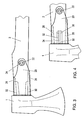
- Fig. 1 eine Axt mit Stiel (teilweise) in Seitenansicht,
- Fig. 2 die Axt aus Fig. 1 von links der Fig. 1 aus gesehen,
- Fig. 3 eine andere Ausführungsform einer Axt und
- Fig. 4 eine weitere Ausführungsform einer Axt.
- Obgleich im folgenden die Erfindung an Hand von Ausführungsbeispielen von Äxten beschrieben wird, ist darauf hinzuweisen, dass die Erfindung grundsätzlich für jede Art von (Schlag)-Werkzeug mit Kopf und Stiel anwendbar ist. So ist die Erfindung, abgesehen von Äxten und Hacken oder Beilen auch für Hämmer, Schlägel, Pickel, Krampen und ähnliche Werkzeuge, bei welchen ein, beispielsweise aus Metall oder Kunststoff bestehender, Werkzeugkopf, mit einem Stiel (z.B. aus Holz, Kunststoff, Metall, faserverstärktem Kunststoff (Glasfasern und/oder Carbonfasern) oder Werkstoffkombinationen) als Handhabe verbunden ist.
- Bei der in Fig. 1 gezeigten Ausführungsform besteht die Axt im Wesentlichen aus einem Kopf 1 und einem Stiel 2. Letzterer ist in Fig. 1 nur teilweise dargestellt.
- Zum Verbinden des Stiels 2 mit dem Kopf 1 der Axt ist anders als bei bekannten Schlagwerkzeugen im Kopf 1 kein Querloch vorgesehen, in das der Stiel 2 eingesteckt und dort festgeklemmt (festgekeilt) wird. Vielmehr ist der Kopf 1 ohne Querloch ausgebildet. Zum Verbinden von Stiel 2 und Kopf 1 ist eine Haltelasche 3 vorgesehen, die im Wesentlichen U-förmig ausgebildet ist. Im Bereich des Steges 4 der U-förmigen Haltelasche 3 ist der obere Teil des Kopfes 1 der Axt aufgenommen. Die Schenkel 5 der Haltelasche 3 ragen über den Kopf 1 hinaus bis in den kopfseitigen Bereich des Stiels 2. Im Bereich der Enden der Schenkel 5 der U-förmigen Haltelasche 3 ist ein Befestigungsbolzen 6 vorgesehen, welcher den Stiel 2 und entsprechende Löcher in den Schenkeln 5 der Haltelasche 3 durchsetzt.
- Über das kopfseitige Ende des Stieles 2 ist ein Rohr 8 geschoben, das bis zur stielseitigen Fläche des Kopfes 1 reicht.
- Das kopfseitige Ende des Stieles 2 ist verjüngt ausgebildet - es ist wenigstens weniger hoch als der Stiel 2 - wobei zwischen das Rohr 8 und das verjüngte Ende des Stiels 2 Einlagen 9 eingesetzt sind. Die Einlagen 9 bestehen aus elastischem Werkstoff, zum Beispiel Gummi oder einem elastomeren Kunststoff. An Stelle gummielastischer Einlagen können auch metallische Federn, z.B. in Form von gewellten Blatt-Federn, vorgesehen sein.
- Dank der beschriebenen Konstruktion kann sich der Kopf 1 gegenüber dem Stiel 2 unter elastischem Verformen der Einlagen 9 bewegen, sodass beim Aufschlagen des Kopfes 1 der Axt, beispielsweise beim Hacken von Holz, auf die den Stiel 2 haltende Hand keine Stoßkraft mehr ausgeübt wird, da am Ende der Stielbewegung die Stoßkraft durch definiertes Abfedern verringert wird. Dank der gewählten Konstruktion der Abfederung, also der federnden Halterung des Kopfes 1 am Stiel 2 (elastische Verbindung zwischen Kopf 1 und Stiel 2) wird die Führigkeit des Werkzeuges, im Beispiel der Axt, nicht nachteilig beeinflusst.
- Die erfindungsgemäße Konstruktion hat den Vorteil, dass die bislang bei Werkzeugköpfen, Axtköpfen und dgl. vorgesehenen Querbohrungen für das Befestigen des Stiels als Handhabe für das Werkzeug in Ausführungsform der Erfindung nicht mehr erforderlich sind. Dadurch sind auch die bekannten Probleme bei der Stielbefestigung und der Rissbildung im Schlagkopf im Bereich der Stielöffnung zuverlässig vermieden.
- Dank der erfindungsgemäßen Ausbildung ist ein Monoblockschlagkopf möglich.
- Der Kopf des Werkzeugs kann prismatisch oder zylindrisch sein. Die Wirkflächen können entsprechend der zu leistenden Arbeit flach, bombiert, spitz, dachförmig und ähnliches ausgebildet sein.
- Die Anschlussstellen des Stiels können prismatische Vertiefungen, zylindrische Vertiefungen, erhabene Leisten, gebrochene Kanten oder bei zylindrischen Schlagkörpern taillierte Eindrehungen oder Erhebungen, wie Rippen, aufweisen.
- Bei dem in den Fig. 1 und 2 gezeigten (Schlag)-Werkzeug sind zwischen dem Rohr 8 und dem Stiel 2 nicht nur in der Nähe des Kopfes 1, sondern auch im Bereich der Enden der Schenkel 5 der Haltelasche 3 elastische Einlagen 9, die als "Federung" für die Schenkel 5 der Haltelasche 3 dienen, vorgesehen.
- Bei der in den Fig. 1 und 2 gezeigten Ausführungsformen eines erfindungsgemäßen Werkzeugs, bei der zwischen dem Rohr 8 und dem Stiel 2 nicht nur in der Nähe des Kopfes 1, sondern auch im Bereich der Schenkel 5 der Haltelasche 3 elastische Einlagen 9 wie ein Schlauch über den Stiel 2 geschoben sind, ist das Rohr 8 über die Bolzen 7 und 6 mit den Schenkeln 5 der Haltelasche 3 unbeweglich verbunden ist. Dabei ist die Baueinheit bestehend aus Außenrohr 8, Haltebügel 3 und Kopf 1 am kopfseitigen Ende des Stiels 2, gegenüber diesem durch die Einlagen 9 elastisch beweglich abgestützt.
- Die Relativbewegung zwischen dem Kopf 3 zusammen mit den Schenkeln der Haltelasche 3 gegenüber dem Stiel 2 wird durch Verformen der Einlagen 9 zwischen dem Außenrohr 8 und dem Ende des Stieles 2 gewährleistet.
- Da auch zwischen den Schenkeln 5 der Haltelasche 3 und dem Stiel 2 eine Einlage 9 vorhanden ist, ist auch in der Querrichtung eine begrenzte Relativbewegung des Kopfes 1 relativ zum Stiel 2 möglich, um auch eine seitlich wirkende Beschleunigungskomponente zu mindern.
- Bei dem Werkzeug von Fig. 1 und Fig. 2 sind zur formschlüssigen Verbindung von Kopf 1 und Haltelasche 3 zwei die Schenkel 5 durchgreifende Bolzen 7 vorgesehen sind.
- In einer nicht gezeigten, abgeänderten Ausführungsform kann bei dem erfindungsgemäßen Schlagwerkzeug auch vorgesehen sein, dass die Haltelasche 3 mit ihrem Steg 4 in eine Ausnehmung an der Vorderseite des Kopfes 1 eingreift. In diesem Fall sind die zum Fixieren des Kopfes 1 an der Haltelasche 3 vorgesehenen Bolzen 7 entbehrlich.
- In einer weiteren, abgeänderten Ausführungsform kann die Haltelasche 3, insbesondere im Bereich ihrer Schenkel 5, mit dem Kopf 1 des Werkzeuges verbunden sein. Diese Verbindung kann beispielsweise durch Schweißen, Kleben oder ähnliches erfolgen. Bei dieser Ausführungsform ist der Steg 4 der Haltelasche 3 nicht mehr erforderlich, so dass bei dieser Ausführungsform die "Haltelasche 3" auf ihre beiden als Laschen ausgebildeten Schenkel 5 reduziert sein kann, also nicht mehr "bügelförmig" ist.
- Auch bei den zuletzt beschriebenen Ausführungsformen der Erfindung werden die Schenkel 5 gegenüber dem Stiel 2 durch ein Außenrohr 8, das über die Schenkel 5 und das kopfseitige Ende des Stiels 2 geschoben ist, so wie bei der zuvor beschriebenen Ausführungsform gesichert.
- Bei der in Fig. 3 gezeigten Ausführungsform ist der Kopf 1 mit einer Hülse 20 verbunden, z.B. verschweißt. Das kopfseitige Ende des Stieles 2 ist in der Hülse 20 aufgenommen. Die Verbindung zwischen Hülse 20 und Stiel 2 erfolgt mit Hilfe eines Bolzens 22, der in einem in einer Bohrung im Stiel 2 eingesetzten Rohrstück 24 aufgenommen ist. Das Rohrstück 24 liegt von innen an der Hülse 20 an, wobei (nur) der Bolzen 22 Löcher in der Hülse 20 durchgreift, sodass die Hülse 20 um die Achse des Bolzens 22 gegenüber dem Stiel 2 schwenkbar ist, da der Stiel 2 an seinem kopfseitigen Ende durch Ausnehmungen 26, 28 verjüngt ist. Der Bolzen 22 ist mit der Hülse 20 verbunden, beispielsweise indem seine die Löcher in der Hülse 20 durchgreifenden Enden mit der Hülse 20 vernietet sind.
- Zwischen dem durch die Ausnehmungen 26, 28 verjüngten, kopfseitigen Ende des Stieles 2 und der Hülse 20 sind oben und unten federelastische Einlagekörper 30, 32 vorgesehen.
- Elastische Einlagen (Kunststoff) können auch zwischen den seitlichen Wangen der Hülse 20 und den seitlichen Flächen des Stieles 2 angeordnet sein.
- In der Ausführungsform von Fig. 4 sind die elastischen Einlagekörper 30, 32 in das Innere des Stieles 2 verlegt. Zwischen den Einlagekörpern 30, 32 ist ein mit dem Kopf 1 und/oder mit der Hülse 20 verbundener Eingriffskörper 34 angeordnet. Die Einlagekörper 30, 32 sind ebenso wie der Eingriffskörper 34 in einem zum kopfseitigen Ende des Stieles 2 hin offenen Loch 36 (Sackloch) aufgenommen. Das Loch 36 kann sich bis zu den Seitenflächen des Stiels 2 erstrecken und ist dann als Schlitz ausgebildet.
Claims (9)
- Werkzeug mit einem Stiel (2) und einem am Stiel (2) befestigten Kopf (1), wobei der Kopf (1) am Stiel (2) gegenüber dem Stiel (2) begrenzt beweglich befestigt und durch elastische Einlagen federnd abgestützt ist, dadurch gekennzeichnet, dass der Kopf (1) des Werkzeuges keine Öffnung für die Aufnahme des Stiels (2) aufweist, dass der Stiel (2) mit seinem kopfseitigen Ende dem Kopf (1) benachbart angeordnet ist, dass der Kopf (2) mit einem Rohr (8) oder mit einer Hülse (20) verbunden ist, dass das Rohr (8) bzw. die Hülse (20) gegenüber dem Stiel (2) durch elastische Körper (30, 32) federnd abgestützt ist, und dass das Rohr (8) bzw. die Hülse (20) gegenüber dem Stiel (2) verschwenkbar und mit dem Stiel (2) über einen Bolzen (22) verbunden ist.
- Werkzeug nach Anspruch 1, dadurch gekennzeichnet, dass der Bolzen (22) in einer Querbohrung des Stiels (2) aufgenommen ist.
- Werkzeug nach Anspruch 2, dadurch gekennzeichnet, dass der Bolzen (22) in einem Rohrstück (24) sitzt, das in der Querbohrung des Stiels (2) sitzt.
- Werkzeug nach Anspruch 3, dadurch gekennzeichnet, dass das Rohrstück (24) mit seinen Enden an der Hülse (29) anliegt.
- Werkzeug nach einem der Ansprüche 1 bis 4, dadurch gekennzeichnet, dass der Bolzen (22) mit der Hülse (20) verbunden ist.
- Werkzeug nach einem der Ansprüche 1 bis 5, dadurch gekennzeichnet, dass das in der Hülse (20) aufgenommene Ende des Stiels (2) gegenüber der Innenfläche der Hülse (20) Spiel hat.
- Werkzeug nach einem der Ansprüche 1 bis 6, dadurch gekennzeichnet, dass zwischen Stiel (2) und Hülse (20) zwei Einlagekörper (30, 32) vorgesehen sind.
- Werkzeug nach Anspruch 7, dadurch gekennzeichnet, dass je ein Einlagekörper (30, 32) oberhalb und unterhalb des Stieles (2) angeordnet ist.
- Werkzeug nach Anspruch 7, dadurch gekennzeichnet, dass die Einlagekörper (30, 32) in einer zum Kopf (1) hin offenen Ausnehmung (36) des Stiels (2) aufgenommen sind, und dass zwischen den Einlagekörpern (30, 32) ein mit dem Kopf (1) und/oder der Hülse (20) verbundener Eingriffskörper (34) angeordnet ist.
Priority Applications (1)
| Application Number | Priority Date | Filing Date | Title |
|---|---|---|---|
| AT05450087T ATE347976T1 (de) | 2004-05-13 | 2005-05-12 | Werkzeug mit einem stiel |
Applications Claiming Priority (2)
| Application Number | Priority Date | Filing Date | Title |
|---|---|---|---|
| AT83504 | 2004-05-13 | ||
| AT8352004 | 2004-05-13 |
Publications (2)
| Publication Number | Publication Date |
|---|---|
| EP1595656A1 EP1595656A1 (de) | 2005-11-16 |
| EP1595656B1 true EP1595656B1 (de) | 2006-12-13 |
Family
ID=34943335
Family Applications (1)
| Application Number | Title | Priority Date | Filing Date |
|---|---|---|---|
| EP05450087A Expired - Lifetime EP1595656B1 (de) | 2004-05-13 | 2005-05-12 | Werkzeug mit einem Stiel |
Country Status (3)
| Country | Link |
|---|---|
| EP (1) | EP1595656B1 (de) |
| AT (1) | ATE347976T1 (de) |
| DE (1) | DE502005000228D1 (de) |
Family Cites Families (5)
| Publication number | Priority date | Publication date | Assignee | Title |
|---|---|---|---|---|
| US1919128A (en) * | 1931-04-15 | 1933-07-18 | Chalmers R Redden | Claw hammer |
| SE462616B (sv) * | 1989-06-21 | 1990-07-30 | Stefan Erikslund | Stoetdaempat slagverktyg |
| US5871204A (en) * | 1995-12-04 | 1999-02-16 | Spirer; Steven E. | Hand tool with adjustable head |
| US5992270A (en) * | 1996-09-06 | 1999-11-30 | Hultafors Ab | Shock absorbing hammer |
| US6739218B2 (en) * | 2002-04-17 | 2004-05-25 | Tai-Her Yang | Hammer with resilient swivel pivoted joint |
-
2005
- 2005-05-12 AT AT05450087T patent/ATE347976T1/de active
- 2005-05-12 DE DE502005000228T patent/DE502005000228D1/de not_active Expired - Lifetime
- 2005-05-12 EP EP05450087A patent/EP1595656B1/de not_active Expired - Lifetime
Also Published As
| Publication number | Publication date |
|---|---|
| EP1595656A1 (de) | 2005-11-16 |
| DE502005000228D1 (de) | 2007-01-25 |
| ATE347976T1 (de) | 2007-01-15 |
Similar Documents
| Publication | Publication Date | Title |
|---|---|---|
| DE3312195C2 (de) | ||
| EP1882559B1 (de) | Handwerkzeuggerät mit Entkoppelungsanordnung | |
| DE69711117T2 (de) | Schlagwerkzeug mit reduzierter Vibration,Dämpfungsmittel für dieses Werkzeug und Verfahren zur Vibrationsdämpfung | |
| DE29916588U1 (de) | Handwerkzeug mit Zangenfunktion | |
| CH632032A5 (de) | Loesbare befestigung eines rueckwaerts mit einer huelse versehenen baggerzahnes an einem in die huelse eingreifenden zahnhalter. | |
| DE3447401A1 (de) | Hammer mit schutzhaube | |
| DE10034742A1 (de) | Werkzeug mit zugeordnetem Schlagwerkzeug | |
| EP2069109A1 (de) | Elektrowerkzeugmaschine mit schwingungsentkoppeltem griffelement | |
| EP0968789B1 (de) | Kupplungsvorrichtung | |
| EP3140081B1 (de) | Handwerkzeugmaschine | |
| DE102005010678B4 (de) | Vorrichtung zur Befestigung eines Rundschaftmeißels | |
| DE3004568A1 (de) | Schneidwerkzeug mit einem auswechselbaren hartmetall-schneideinsatz | |
| DE69031836T2 (de) | Abrisshammer | |
| EP1595656A1 (de) | Werkzeug mit einem Stiel | |
| AT8591U1 (de) | Werkzeug | |
| CH667301A5 (de) | Vorrichtung zum einspannen eines stabes fuer eine einrichtung zum absenken des stabes in den erdboden. | |
| EP1840049B1 (de) | Greifelement für eine Gasflasche | |
| DE202007013174U1 (de) | Schraubenschlüssel mit ausziehbarem Schraubendreher als Antriebswerkzeug | |
| AT501861B1 (de) | Handgeführter, vibrationsgedämpfter drucklufthammer | |
| DE3041531C2 (de) | Schlagwerkzeug | |
| DE102020125134A1 (de) | Räumleiste für den Räumschild eines Schneepfluges | |
| EP0537875B1 (de) | Fluid betriebenes Schlagwerkzeug | |
| DE1478788A1 (de) | Hammerbetaetigter Schraubenschluessel | |
| DE8716386U1 (de) | Druckluftbetätigter Meißelhammer | |
| AT10480U1 (de) | Handwerkzeug mit stiel |
Legal Events
| Date | Code | Title | Description |
|---|---|---|---|
| PUAI | Public reference made under article 153(3) epc to a published international application that has entered the european phase |
Free format text: ORIGINAL CODE: 0009012 |
|
| AK | Designated contracting states |
Kind code of ref document: A1 Designated state(s): AT BE BG CH CY CZ DE DK EE ES FI FR GB GR HU IE IS IT LI LT LU MC NL PL PT RO SE SI SK TR |
|
| AX | Request for extension of the european patent |
Extension state: AL BA HR LV MK YU |
|
| 17P | Request for examination filed |
Effective date: 20051128 |
|
| GRAP | Despatch of communication of intention to grant a patent |
Free format text: ORIGINAL CODE: EPIDOSNIGR1 |
|
| AKX | Designation fees paid |
Designated state(s): AT BE BG CH CY CZ DE DK EE ES FI FR GB GR HU IE IS IT LI LT LU MC NL PL PT RO SE SI SK TR |
|
| AXX | Extension fees paid |
Extension state: HR Payment date: 20051128 |
|
| GRAS | Grant fee paid |
Free format text: ORIGINAL CODE: EPIDOSNIGR3 |
|
| GRAA | (expected) grant |
Free format text: ORIGINAL CODE: 0009210 |
|
| RAP1 | Party data changed (applicant data changed or rights of an application transferred) |
Owner name: HIMMELBERGER ZEUGHAMMERWERK LEONHARD MUELLER & SOE |
|
| AK | Designated contracting states |
Kind code of ref document: B1 Designated state(s): AT BE BG CH CY CZ DE DK EE ES FI FR GB GR HU IE IS IT LI LT LU MC NL PL PT RO SE SI SK TR |
|
| AX | Request for extension of the european patent |
Extension state: HR |
|
| PG25 | Lapsed in a contracting state [announced via postgrant information from national office to epo] |
Ref country code: CZ Free format text: LAPSE BECAUSE OF FAILURE TO SUBMIT A TRANSLATION OF THE DESCRIPTION OR TO PAY THE FEE WITHIN THE PRESCRIBED TIME-LIMIT Effective date: 20061213 Ref country code: DK Free format text: LAPSE BECAUSE OF FAILURE TO SUBMIT A TRANSLATION OF THE DESCRIPTION OR TO PAY THE FEE WITHIN THE PRESCRIBED TIME-LIMIT Effective date: 20061213 Ref country code: SI Free format text: LAPSE BECAUSE OF FAILURE TO SUBMIT A TRANSLATION OF THE DESCRIPTION OR TO PAY THE FEE WITHIN THE PRESCRIBED TIME-LIMIT Effective date: 20061213 Ref country code: RO Free format text: LAPSE BECAUSE OF FAILURE TO SUBMIT A TRANSLATION OF THE DESCRIPTION OR TO PAY THE FEE WITHIN THE PRESCRIBED TIME-LIMIT Effective date: 20061213 Ref country code: LT Free format text: LAPSE BECAUSE OF FAILURE TO SUBMIT A TRANSLATION OF THE DESCRIPTION OR TO PAY THE FEE WITHIN THE PRESCRIBED TIME-LIMIT Effective date: 20061213 Ref country code: SK Free format text: LAPSE BECAUSE OF FAILURE TO SUBMIT A TRANSLATION OF THE DESCRIPTION OR TO PAY THE FEE WITHIN THE PRESCRIBED TIME-LIMIT Effective date: 20061213 Ref country code: PL Free format text: LAPSE BECAUSE OF FAILURE TO SUBMIT A TRANSLATION OF THE DESCRIPTION OR TO PAY THE FEE WITHIN THE PRESCRIBED TIME-LIMIT Effective date: 20061213 Ref country code: IE Free format text: LAPSE BECAUSE OF FAILURE TO SUBMIT A TRANSLATION OF THE DESCRIPTION OR TO PAY THE FEE WITHIN THE PRESCRIBED TIME-LIMIT Effective date: 20061213 |
|
| REG | Reference to a national code |
Ref country code: GB Ref legal event code: FG4D Free format text: NOT ENGLISH |
|
| REG | Reference to a national code |
Ref country code: CH Ref legal event code: EP Ref country code: CH Ref legal event code: NV Representative=s name: RIEDERER HASLER & PARTNER PATENTANWAELTE AG |
|
| REG | Reference to a national code |
Ref country code: IE Ref legal event code: FG4D Free format text: LANGUAGE OF EP DOCUMENT: GERMAN |
|
| REF | Corresponds to: |
Ref document number: 502005000228 Country of ref document: DE Date of ref document: 20070125 Kind code of ref document: P |
|
| PG25 | Lapsed in a contracting state [announced via postgrant information from national office to epo] |
Ref country code: BG Free format text: LAPSE BECAUSE OF FAILURE TO SUBMIT A TRANSLATION OF THE DESCRIPTION OR TO PAY THE FEE WITHIN THE PRESCRIBED TIME-LIMIT Effective date: 20070313 |
|
| PG25 | Lapsed in a contracting state [announced via postgrant information from national office to epo] |
Ref country code: ES Free format text: LAPSE BECAUSE OF FAILURE TO SUBMIT A TRANSLATION OF THE DESCRIPTION OR TO PAY THE FEE WITHIN THE PRESCRIBED TIME-LIMIT Effective date: 20070324 |
|
| REG | Reference to a national code |
Ref country code: SE Ref legal event code: TRGR |
|
| PG25 | Lapsed in a contracting state [announced via postgrant information from national office to epo] |
Ref country code: IS Free format text: LAPSE BECAUSE OF FAILURE TO SUBMIT A TRANSLATION OF THE DESCRIPTION OR TO PAY THE FEE WITHIN THE PRESCRIBED TIME-LIMIT Effective date: 20070413 |
|
| PG25 | Lapsed in a contracting state [announced via postgrant information from national office to epo] |
Ref country code: PT Free format text: LAPSE BECAUSE OF FAILURE TO SUBMIT A TRANSLATION OF THE DESCRIPTION OR TO PAY THE FEE WITHIN THE PRESCRIBED TIME-LIMIT Effective date: 20070514 |
|
| ET | Fr: translation filed | ||
| GBV | Gb: ep patent (uk) treated as always having been void in accordance with gb section 77(7)/1977 [no translation filed] |
Effective date: 20061213 |
|
| PLBE | No opposition filed within time limit |
Free format text: ORIGINAL CODE: 0009261 |
|
| STAA | Information on the status of an ep patent application or granted ep patent |
Free format text: STATUS: NO OPPOSITION FILED WITHIN TIME LIMIT |
|
| 26N | No opposition filed |
Effective date: 20070914 |
|
| PG25 | Lapsed in a contracting state [announced via postgrant information from national office to epo] |
Ref country code: GB Free format text: LAPSE BECAUSE OF FAILURE TO SUBMIT A TRANSLATION OF THE DESCRIPTION OR TO PAY THE FEE WITHIN THE PRESCRIBED TIME-LIMIT Effective date: 20061213 |
|
| PG25 | Lapsed in a contracting state [announced via postgrant information from national office to epo] |
Ref country code: MC Free format text: LAPSE BECAUSE OF NON-PAYMENT OF DUE FEES Effective date: 20070531 |
|
| PG25 | Lapsed in a contracting state [announced via postgrant information from national office to epo] |
Ref country code: GR Free format text: LAPSE BECAUSE OF FAILURE TO SUBMIT A TRANSLATION OF THE DESCRIPTION OR TO PAY THE FEE WITHIN THE PRESCRIBED TIME-LIMIT Effective date: 20070314 |
|
| PG25 | Lapsed in a contracting state [announced via postgrant information from national office to epo] |
Ref country code: EE Free format text: LAPSE BECAUSE OF FAILURE TO SUBMIT A TRANSLATION OF THE DESCRIPTION OR TO PAY THE FEE WITHIN THE PRESCRIBED TIME-LIMIT Effective date: 20061213 |
|
| PG25 | Lapsed in a contracting state [announced via postgrant information from national office to epo] |
Ref country code: CY Free format text: LAPSE BECAUSE OF FAILURE TO SUBMIT A TRANSLATION OF THE DESCRIPTION OR TO PAY THE FEE WITHIN THE PRESCRIBED TIME-LIMIT Effective date: 20061213 |
|
| PG25 | Lapsed in a contracting state [announced via postgrant information from national office to epo] |
Ref country code: TR Free format text: LAPSE BECAUSE OF FAILURE TO SUBMIT A TRANSLATION OF THE DESCRIPTION OR TO PAY THE FEE WITHIN THE PRESCRIBED TIME-LIMIT Effective date: 20061213 Ref country code: HU Free format text: LAPSE BECAUSE OF FAILURE TO SUBMIT A TRANSLATION OF THE DESCRIPTION OR TO PAY THE FEE WITHIN THE PRESCRIBED TIME-LIMIT Effective date: 20070614 |
|
| PGFP | Annual fee paid to national office [announced via postgrant information from national office to epo] |
Ref country code: LU Payment date: 20100429 Year of fee payment: 6 |
|
| PGFP | Annual fee paid to national office [announced via postgrant information from national office to epo] |
Ref country code: IT Payment date: 20100528 Year of fee payment: 6 Ref country code: NL Payment date: 20100517 Year of fee payment: 6 |
|
| PGFP | Annual fee paid to national office [announced via postgrant information from national office to epo] |
Ref country code: BE Payment date: 20100430 Year of fee payment: 6 Ref country code: CH Payment date: 20100419 Year of fee payment: 6 |
|
| PGFP | Annual fee paid to national office [announced via postgrant information from national office to epo] |
Ref country code: SE Payment date: 20110524 Year of fee payment: 7 Ref country code: FR Payment date: 20110524 Year of fee payment: 7 |
|
| PGFP | Annual fee paid to national office [announced via postgrant information from national office to epo] |
Ref country code: FI Payment date: 20110520 Year of fee payment: 7 |
|
| BERE | Be: lapsed |
Owner name: HIMMELBERGER ZEUGHAMMERWERK LEONHARD MULLER & SOH Effective date: 20110531 |
|
| REG | Reference to a national code |
Ref country code: NL Ref legal event code: V1 Effective date: 20111201 |
|
| REG | Reference to a national code |
Ref country code: CH Ref legal event code: PL |
|
| PG25 | Lapsed in a contracting state [announced via postgrant information from national office to epo] |
Ref country code: LI Free format text: LAPSE BECAUSE OF NON-PAYMENT OF DUE FEES Effective date: 20110531 Ref country code: CH Free format text: LAPSE BECAUSE OF NON-PAYMENT OF DUE FEES Effective date: 20110531 Ref country code: NL Free format text: LAPSE BECAUSE OF NON-PAYMENT OF DUE FEES Effective date: 20111201 |
|
| PG25 | Lapsed in a contracting state [announced via postgrant information from national office to epo] |
Ref country code: IT Free format text: LAPSE BECAUSE OF NON-PAYMENT OF DUE FEES Effective date: 20110512 |
|
| PG25 | Lapsed in a contracting state [announced via postgrant information from national office to epo] |
Ref country code: BE Free format text: LAPSE BECAUSE OF NON-PAYMENT OF DUE FEES Effective date: 20110531 |
|
| REG | Reference to a national code |
Ref country code: SE Ref legal event code: EUG |
|
| PG25 | Lapsed in a contracting state [announced via postgrant information from national office to epo] |
Ref country code: FI Free format text: LAPSE BECAUSE OF NON-PAYMENT OF DUE FEES Effective date: 20120512 |
|
| PG25 | Lapsed in a contracting state [announced via postgrant information from national office to epo] |
Ref country code: SE Free format text: LAPSE BECAUSE OF NON-PAYMENT OF DUE FEES Effective date: 20120513 |
|
| REG | Reference to a national code |
Ref country code: FR Ref legal event code: ST Effective date: 20130131 |
|
| PG25 | Lapsed in a contracting state [announced via postgrant information from national office to epo] |
Ref country code: FR Free format text: LAPSE BECAUSE OF NON-PAYMENT OF DUE FEES Effective date: 20120531 |
|
| PG25 | Lapsed in a contracting state [announced via postgrant information from national office to epo] |
Ref country code: LU Free format text: LAPSE BECAUSE OF NON-PAYMENT OF DUE FEES Effective date: 20110512 |
|
| PGFP | Annual fee paid to national office [announced via postgrant information from national office to epo] |
Ref country code: DE Payment date: 20170517 Year of fee payment: 13 |
|
| PGFP | Annual fee paid to national office [announced via postgrant information from national office to epo] |
Ref country code: AT Payment date: 20170530 Year of fee payment: 13 |
|
| REG | Reference to a national code |
Ref country code: DE Ref legal event code: R119 Ref document number: 502005000228 Country of ref document: DE |
|
| REG | Reference to a national code |
Ref country code: AT Ref legal event code: MM01 Ref document number: 347976 Country of ref document: AT Kind code of ref document: T Effective date: 20180512 |
|
| PG25 | Lapsed in a contracting state [announced via postgrant information from national office to epo] |
Ref country code: AT Free format text: LAPSE BECAUSE OF NON-PAYMENT OF DUE FEES Effective date: 20180512 |
|
| PG25 | Lapsed in a contracting state [announced via postgrant information from national office to epo] |
Ref country code: DE Free format text: LAPSE BECAUSE OF NON-PAYMENT OF DUE FEES Effective date: 20181201 |