EP1591899A2 - Reproduction de données dans un système de stockage - Google Patents
Reproduction de données dans un système de stockage Download PDFInfo
- Publication number
- EP1591899A2 EP1591899A2 EP05007538A EP05007538A EP1591899A2 EP 1591899 A2 EP1591899 A2 EP 1591899A2 EP 05007538 A EP05007538 A EP 05007538A EP 05007538 A EP05007538 A EP 05007538A EP 1591899 A2 EP1591899 A2 EP 1591899A2
- Authority
- EP
- European Patent Office
- Prior art keywords
- volume
- replication
- storage control
- control unit
- data
- Prior art date
- Legal status (The legal status is an assumption and is not a legal conclusion. Google has not performed a legal analysis and makes no representation as to the accuracy of the status listed.)
- Withdrawn
Links
Images


Classifications
-
- G—PHYSICS
- G06—COMPUTING; CALCULATING OR COUNTING
- G06F—ELECTRIC DIGITAL DATA PROCESSING
- G06F11/00—Error detection; Error correction; Monitoring
- G06F11/07—Responding to the occurrence of a fault, e.g. fault tolerance
- G06F11/16—Error detection or correction of the data by redundancy in hardware
- G06F11/20—Error detection or correction of the data by redundancy in hardware using active fault-masking, e.g. by switching out faulty elements or by switching in spare elements
- G06F11/2053—Error detection or correction of the data by redundancy in hardware using active fault-masking, e.g. by switching out faulty elements or by switching in spare elements where persistent mass storage functionality or persistent mass storage control functionality is redundant
- G06F11/2056—Error detection or correction of the data by redundancy in hardware using active fault-masking, e.g. by switching out faulty elements or by switching in spare elements where persistent mass storage functionality or persistent mass storage control functionality is redundant by mirroring
- G06F11/2082—Data synchronisation
-
- G—PHYSICS
- G06—COMPUTING; CALCULATING OR COUNTING
- G06F—ELECTRIC DIGITAL DATA PROCESSING
- G06F11/00—Error detection; Error correction; Monitoring
- G06F11/07—Responding to the occurrence of a fault, e.g. fault tolerance
- G06F11/16—Error detection or correction of the data by redundancy in hardware
- G06F11/20—Error detection or correction of the data by redundancy in hardware using active fault-masking, e.g. by switching out faulty elements or by switching in spare elements
- G06F11/2053—Error detection or correction of the data by redundancy in hardware using active fault-masking, e.g. by switching out faulty elements or by switching in spare elements where persistent mass storage functionality or persistent mass storage control functionality is redundant
- G06F11/2056—Error detection or correction of the data by redundancy in hardware using active fault-masking, e.g. by switching out faulty elements or by switching in spare elements where persistent mass storage functionality or persistent mass storage control functionality is redundant by mirroring
- G06F11/2069—Management of state, configuration or failover
Definitions
- the present invention relates to a storage system and a data replication method, and more particularly to a storage system comprising plural storage control units to which plural disk devices are connected, and a data replication method for creation of replication.
- the prior art enabling to backup data stored in a storage device without stopping the daily jobs of the corporations includes, for example, snapshot technologies proposed as described in JP-A-7-210439 and JP-A-2001-318833.
- the snapshot is a function to copy a storage area possessed by the storage device at a specified time to a storage device without through a computer connected to the storage device. Using such a snapshot function, a user can use the original storage area for jobs and the data stored in the copied storage area for backup.
- the storage system of the cluster configuration is a system having a conventional storage system such as a disk array device as one cluster and one storage system configured of plural clusters.
- the present invention has been made under the circumstances described above to remedy the problems of the above-described prior arts and provides a storage system of a cluster configuration having plural storage control units to which plural disk devices are connected, which can generate a copy of the storage area without conscious of different storage control units not only when replication is created in a volume within the disk devices connected to the same storage control unit but also when replication is created in a volume within the disk devices connected to different storage control units, and a data replication method.
- a storage system comprising a plurality of storage control units to which plural disk devices are connected and a data replication method thereof, wherein each of the plural storage control units includes a replication creation unit which creates replication of data of a volume in the disk devices and pair information which is information about a volume of a replication source and a volume of a replication destination; and wherein, when the replication creation unit in one of the plural storage control units is to create replication in a volume within the disk devices connected to another storage control unit, all data in the volume of the replication source is copied to the volume of the replication destination, and when the storage control unit having the volume of the replication source receives a data update request to the volume of the replication source, the received data is stored in a cache memory of the storage control unit, the data is stored in a cache memory of the storage control unit of the replication destination on an extension of processing of the update request, and the update of data is reflected to the replication destination to prepare a replication volume.
- a storage system of a cluster configuration having plural storage control units to which disk devices are connected can create a copy of a storage area without degrading the performance by minimizing accesses to control information among the control units when replication is created in a volume within the disk devices connected to different storage control units.
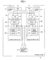
- Fig. 1 is a block diagram showing a hardware configuration of a computer system including a storage system according to a first embodiment of the present invention.
- numeral 10 indicates a host
- numerals 20A and 20B indicate storage control units
- numerals 21A and 21B indicate CPUs
- numerals 22A and 22B indicate memories
- numerals 23A and 23B indicate cache memories
- numeral 24 indicates a hub
- numerals 25A and 25B indicate switches
- numeral 31 indicates a storage group
- numeral 40 indicates an I/F adaptor
- numeral 70 indicates a storage system
- numeral 80 indicates a user input/output apparatus.
- the computer system including the storage system according to the first embodiment of the present invention is configured with the host 10 connected to the storage system 70 via the I/F adaptor 40.
- the storage system 70 is configured of the plural storage control units 20A, 20B, the I/F adaptor 40 connected to the individual storage control units 20A, 20B, the user input/output apparatus 80 connected to the individual storage control units 20A, 20B via a management network, and the storage group 31 connected to the I/F adaptor 40.
- the I/F adaptor 40 is a channel connection part independent of the storage control units 20A, 20B.
- the shown storage system is connected to the storage system 70 and the host 10 or the storage group 31 via a different board not shown.
- the storage group 31 is a group of storage devices having a plurality of storage devices such as magnetic disk devices.
- the storage control units 20A, 20B each have the CPUs 21A, 21B, the memories 22A, 22B and the cache memories 23A, 23B for temporarily storing I/O data from the host 10.
- the CPUs 21A, 21B, the memories 22A, 22B and the cache memories 23A, 23B are multiplexed and mutually connected by the switches 25.
- the storage control units 20A, 20B each are configured to allow the CPU in them to access the memory and the cache memory therein.
- the I/F adapter 40 having received an I/O request from the host 10 sends the pertinent request to the storage control units 20A, 20B.
- the CPUs 21A, 21B in the storage control units 20A, 20B obtain and analyze the command, and if the request is read, judge whether the cache memories 23A, 23B have the object data therein; if the data is available, the CPUs 21A, 21B send the data to the host 10 via the hub 24 within the I/F adapter 40 but, if the cache memory 23 does not have the data, secure a region in the cache memories 23A, 23B, read out data from the storage group 31, execute staging in the region secured in the cache memories 23A, 23B and send the data to the host 10.
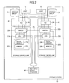
- Fig. 2 is a block diagram showing a hardware configuration of a computer system including a storage system according to a second embodiment of the present invention, and numerals in Fig. 2 are same as those in Fig. 1.
- the computer system including the storage system according to the second embodiment of the present invention shown in Fig. 2 is different from the first embodiment of the present invention shown in Fig. 1 on the point that the switch 25A in the storage control unit 20A and the switch 25B in the storage control unit 20B are mutually connected, and the storage control units 20A and 20B are mutually connected.
- the storage control units 20A, 20B are mutually connected via the switches 25A, 25B in the second embodiment, so that the individual CPUs in the storage control units 20A, 20B can access the memory in the other storage control unit.
- connection line 64 between the switch 25A of the storage control unit 20A and the switch 25B of the storage control unit 20B may be a bus or a network. But, when the storage control units mutually access the memory and cache memory in the other storage control unit in the second embodiment shown in Fig. 2, the connection line 64 (a bus or a network configured of hardware) has a slow access speed in performance as compared with the case of accessing the memory and cache memory in the same storage control unit.
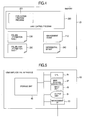
- Fig. 3 is a block diagram showing a structure of the storage system according to a third embodiment of the present invention.
- numeral 25 indicates a device interface
- numeral 32 indicates a storage group
- numeral 50 indicates a processor
- numerals 60 to 63 indicate networks
- numeral 510 indicates a configuration information table
- other numerals are same as those in Fig. 1.
- the computer system including the storage system according to the third embodiment of the present invention shown in Fig. 3 is configured with a first storage system 70A connected to the host 10 via the network 60 and the first storage system 70A and a second storage system 70B connected via the network 61.
- a user input/output apparatus 80 can be connected to each part in the first storage system 70A via the management networks 62, 63.
- the first and second storage systems 70A, 70B are configured in the same way, but only the first storage system 70A is shown its inside structure in Fig. 3, and the inside structure of the storage system 70B is omitted.
- the second storage system 70B is connected, but the present invention may have the structure without connecting the second storage system 70B.
- the first and second storage systems 70A, 70B are basically storage systems having the same functional structure as those described with reference to Fig. 1 and Fig. 2.
- the first storage system 70A is provided with plural I/F adaptors 40 which are channel connection portions independent of the storage control units 20A, 20B and treat protocols in conformity with LAN (Local Area Network), public line, dedicated line and ESCON (Enterprise Systems Connection); the plural I/F adaptors 40 and the plural storage control units 20A, 20B are connected via the network 63.
- the processor 50 having the configuration information table 510 is connected to the network 63
- the storage group 31 is connected to the storage control unit 20A via the device interface 25A.
- the I/F adaptor 40 receives an I/O request from the host 10, analyzes the command to perform protocol conversion, judges LU (Logical Unit), in which data demanded by the command is stored, whether it is managed under control of either of the storage control units 20A and 20B or by the storage system 70B, and sends the I/O request to the judged location. It is judged which device manages the LU storing the above-described request data with reference to the configuration information table 510 stored in the memory within the processor 50 connected via the network 63.
- LU Logical Unit
- the user input/output apparatus 80 recognizes each part within the first storage system 70A via the network 62 but can be configured to directly connect through a dedicated line.
- the storage control unit 20A has a CPU 21A, a memory 22A, a cache memory 23A for temporarily storing I/O data from the host 10, the hub 24 for connection to the network 63 and a device interface 25 for controlling sending/receiving of data to/from the storage group 31, which are mutually connected via an internal bus.
- the storage control unit 20B also has the same configuration.
- Fig. 4 is a diagram showing an internal structure of the memory 22A (the memory 22B also has the same structure, and these memories are simply referred to as the memory 22 below).
- 200 is a RAID (Redundant Array of Inexpensive Disks) control program
- 201 is a replication creation program
- 210 is a management agent
- 220 is a volume pair information table
- 230 is a volume information table
- 240 is a differential bitmap.
- the memory 22 stores various programs to be executed by the CPU 21. Specifically, they are the RAID control program 200 for controlling the operation of the storage systems 70, 70A, 70B and the management agent 210 for managing the storage system configuration.
- the memory 22 also stores various kinds of management information. Specifically, they are the volume pair information table 220 for recording information about a data copy source and copy destination, the volume information table 230, the differential bitmap 240 and a configuration information table (not shown) that the storage system 70B provides the storage system 70A with its own LU as the LU of the storage system 70A.
- the RAID control program 200 has a functional portion (not shown) for issuing a command to the storage group 31, and the RAID control program 200 has therein as a sub-program the replication creation program 201 for creating replication of data within the storage system 70.
- the management agent 210 is a program for setting information about storage device (hereinafter referred to as storage device information) upon receiving input from the user input/output apparatus 80 and outputting storage device information to the user input/output apparatus 80.
- Fig. 5 is a block diagram showing a structure of the user input/output apparatus 80, which will be described below.
- the user input/output apparatus 80 includes a CPU 81, a main storage 82, an input unit (keyboard, etc.) 83, an output unit (display device, etc.) 84, a management I/F 85 for connection with an outside device and a storage unit 86, and they are mutually connected via an internal bus as shown in Fig. 5.
- the host 10 is, for example, a personal computer, a workstation, a general-purpose computer or the like and provided with HBA (Host Bus Adaptor) as an FC interface for connection to the outside.
- HBA Hyper Bus Adaptor
- the HBA is provided with a WWN.
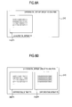
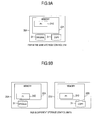
- Fig. 6A and Fig. 6B are diagrams showing an example configuration of the volume pair information table 220.
- the volume pair information table 220 is information for managing a pair of volumes (hereinafter referred to as the pair) for holding the copied data within the storage system 70 (the same is also applied to 70A and 70B; 70 is used to indicate the storage system unless otherwise specified) and includes the fields for a pair number 221, original volume information 222, copy volume information 224, and a pair status 226.
- the volume pair information table 220 includes a volume pair information table 220A in the same storage control unit which is an information table at the time of creation of replication within the same control storage control unit as shown in Fig. 6A and a volume pair information table 220B in a different storage control unit which is an information table at the time of creation of replication within a different storage control unit as shown in Fig. 6B.
- the pair number 221 indicates an identifier arbitrarily allocated to the pair of original and copy volumes.
- the original volume information 222 indicates volume numbers allocated to the original volume among the pairs to which the identifier is given in the table 220A and a storage control unit number 227 and a volume number 223 which are allocated to the original volume among the pairs to which the identifier is given in the table 220B.
- the copy volume information 224 indicates the volume numbers allocated to the copy volume among the pairs to which the identifier is given in the table 220A and indicates a storage control unit number 228 and a volume number 225 which are allocated to the copy volume among the pairs to which the identifier is given in the table 220B.
- the pair status 226 indicates the present status of the pair.
- a status includes a status that data stored in the individual volumes of the pair are synchronized and the contents of the stored data match (hereinafter referred to as a Pair status), a status that data are not synchronized among the pairs (hereinafter referred to as a Split status), and the like.
- the storage system 70 can change, for example, a pair in the Pair status into the Split status in a prescribed time. At this time, data possessed by the pair at the prescribed time is stored in the copy volume (this processing is called "an acquisition of snapshot"). Then, the host 10 reads out data from the copy volume and writes in another storage device, e.g., a tape device, so that data stored in the pair at the time when the snapshot is acquired can be backed up. After the acquisition of the snapshot, the copy volume itself may be stored as backup of the data.
- Information of the pair having a copy source and a copy destination in the storage control unit 20A is stored in the memory 22A within the storage control unit 20A, and information of the pair having a copy source and a copy destination in the storage control unit 20B is stored in the memory 22B within the storage control unit 20B.
- Information of the pair between the storage control units having different copy source and copy destination in the storage control units 20A and 20B is stored in the memory 22A of the storage control units 20A and 20B and volume pair information table 220B in 20B.
- pair number 0 is a pair of volume numbers 100 and 10 in the storage control unit No. 1. It is also seen that pair No. 1 is a pair of volume No. 110 of the storage control unit No. 1 and volume No. 120 of the storage control unit No. 2.
- Fig. 7 is a diagram showing.an example structure of the volume information table 230.
- This volume information table 230 is registered with information for managing the volume under control by the storage control unit 20A and is stored in the memory within the storage control unit 20A and includes the fields for a volume number 231, original/copy 232 indicating the original and copy of a volume, a pair volume number 236 and a volume status 235 indicating whether the volume is being used or not.
- the volume number 231 is an identifier which is allocated to the volume.
- the example shown in Fig. 7 has three pairs set up for volume number 0 of the own storage control unit.
- the example shown in Fig. 7 shows that a first pair indicates that the copy volume which is a pair volume is volume No. 20 of the storage control unit No. 1, and a second pair indicates that the copy volume is volume No. 158 within the same storage control unit (indicated by "-").
- a third pair indicates that the copy volume is volume No. 426 of the storage control unit No. 1.
- volume No. 1 of the own storage control unit is being used as the copy volume of the pair, indicating that the original volume is volume No. 3783 of the storage control unit No. 3.
- a storage control unit number 233 and a volume number 234 in the pair volume information 236 are pair volume information when they are paired. In a case of the pair in the same storage control unit, only the copy volume number is registered in the volume number 234. In a case of a pair between different storage control units, the storage control unit number of the copy volume is registered in the storage control unit number 233 and the volume number is registered in the volume number 234.
- the volume status 235 is information indicating whether the volume is in use or available.
- Fig. 8A and Fig. 8B are diagrams illustrating examples of the differential bitmap 240.
- the differential bitmap has 1 bit corresponded to data having a predetermined size and a value determined as "1" if even 1 bit in the data having a predetermined size of one of the pair is updated, and indicates for each predetermined data size whether the copy between the pairs has completed.
- the differential bitmap has data having a prescribed data size corresponded to a bit, its value "0" indicates a portion where the copy has completed, and the value "1" indicates a portion where the copy has not completed.
- the bit is determined to be "0" so that the content is reflected to the copy destination.
- only one differential bitmap P1 is advantageously provided as shown in Fig. 8A, and in a fourth embodiment of the present invention to be described later, two bitmaps P1 and P2 having the same size are provided for one pair as shown in Fig. 8B.
- Fig. 9A and Fig. 9B are diagrams showing an example arrangement of the differential bitmaps according to the first to third embodiments of the present invention.
- replication When replication is to be created in the same storage control unit as shown in Fig. 9A, its pair is created in, for example, the storage group 31 connected to the storage control unit 20A, and the differential bitmap 240 is created as P1 in the memory 22A of the storage control unit 20A.
- replication When replication is created in different storage control units as shown in Fig. 9B, its pair is created in, for example, the storage group 31 to be connected to the storage control unit 20A and the storage group 31 to be connected to the storage control unit 20B, the differential bitmap 240 is created as P1 in the memory 22A of the storage control unit 20A and as S1 in the memory 22B of the storage control unit 20B. And, the differential bitmaps P1 and S1 are controlled so to match mutually.
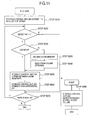
- Fig. 10 is a flowchart illustrating a processing operation to create replication by the storage systems according to the first to third embodiments of the present invention, and this processing operation will be described.
- the copy volume is created by the replication creation program 201.
- the replication creation program 201 checks whether the original and copy volumes of a replication pair are within the same storage control unit or between the different storage control units and performs processing of the pair in the same storage control unit and the pair between the different storage control units.
- Fig. 11 is a flowchart illustrating a processing operation for creation of replication in the same storage control unit by the processing in the above-described step 5030, and this processing operation will be described below.
- redundant information for the copy volume may be created and stored directly as data for the copy volume in the cache memory.
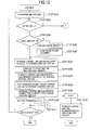
- Fig. 12 is a flowchart illustrating a processing operation of the replication creation between the different storage control units by the processing in the above-described step 5040, and this processing operation will be described below.
- the differential bitmap has all differential bits with a value "0".
- Fig. 13 is a flowchart illustrating an operation in case of a write request during the processing for creation of replication in the same storage control unit described with reference to Fig. 11, and this operation will be described below.
- the storage systems according to the first to third embodiments of the present invention employ a method not using the differential bitmap for a pair extending over the storage control units in response to a read/write request during the initial copy. And, at the time of the initial copy for creation of replication between the different storage control units, "1" is registered for all differential bits of P1 of the differential bitmap 240, and the same processing as that described above is executed. If a write request occurs during this processing, the storage control unit 20A stores data in the cache memory of the own device and transfers data to the storage control unit 20B as a continuation of the same write request.
- Fig. 14 is a flowchart illustrating an operation in case of a write request during the processing for creation of replication between the different storage control units described with reference to Fig. 12, and this operation will be described below.
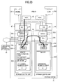
- Fig. 15 is a diagram showing a data transfer path in case of a write request during the processing for creation of replication between the different storage control units described with reference to Fig. 14.
- Fig. 15 also shows an arrangement of the differential bitmap.
- the reflection of update to the copy volume can be executed as a continuation of the same I/O processing when a write request is received.
- the write request for update to the copy volume in this case is sent from the CPU 21A to the CPU 21B through the same route as the data transmission line.
- the storage control unit 20A updates the differential bit of the differential bitmap P1
- the storage control unit 20B updates the differential bit of the differential bitmap S1.
- the embodiments of the present invention have one each of the original and a copy of the differential bitmap, and when the pair is in the split status, the replication processing can be realized by updating the differential bitmap in each storage control unit. If there is a write request to the pair in the same storage control unit, the update position may be stored in the differential bitmap P1.
- Fig. 16 is a flowchart illustrating a processing operation of resynchronization of the pair between the different storage control units of the storage system according to the first to third embodiments of the present invention, and this processing operation will be described below.
- the resynchronization processing (Resync) is a processing for synchronizing the copy volume with the content of the original volume, namely a processing for copying the content of the original volume at that time to the copy volume.
- the copy processing is executed by the same processing as the initial copy described above.
- the bitmap merged by the above-described processing in the step 20050 may be disposed other than the storage control unit 20A.
- the merge processing may be executed by any unit other than the storage control unit 20A.
- the Resync processing can be achieved without increasing the differential bitmap volume. According to this method, the management of the link between the storage control units 20A and 20B can also be simplified.
- the structure in terms of hardware may be the same as in the first to third embodiments of the present invention described above except that two differential bitmaps each are disposed in both of the storage control unit 20A having the original volume and the storage control unit 20B having the copy volume.
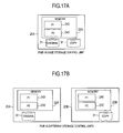
- Fig. 17A and Fig. 17B are diagrams showing example arrangements of the differential bitmap according to the fourth embodiment of the present invention.
- the pair of the original and a copy is created in, for example, a storage group 31 to be connected to the storage control unit 20A as shown in Fig. 17A, and a differential bitmap 240 is previously created in two as P1, P2 in the memory 22A of the storage control unit 20A.
- the pair of the original and a copy is created in, for example, the storage group 31 connected to the storage control unit 20A and the storage group 31 connected to the storage control unit 20B as shown in Fig. 17B
- the differential bitmap 240 is created in two as P1, P2 in the memory 22A of the storage control unit 20A and as S1, S2 in the memory 22B of the storage control unit 20B.
- the differential bitmaps P1, S1 are created at the time of the initial copy, and the differential bitmaps P2, S2 are used in the processing after the pair is split.
- the initial copy may be executed by the same processing as that according to the flowcharts described with reference to Fig. 11 and Fig. 12, and the processing in response to a write request during the copy processing may be executed for the pair in the same storage control unit in the same way as the processing according to the flowchart described with reference to Fig. 13.
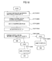
- Fig. 18 is a flowchart illustrating an operation according to the fourth embodiment of the present invention when there is a write request during the processing for creation of the replication between different storage control units, and this operation will be described below.
- the split is generally executed when the initial copy is terminated and the contents of the original volume and the copy volume are synchronized.
- high-speed Split there is a technology called "high-speed Split" in that if a Split request is received during the initial copy, the split completion is immediately reported to the host 10, and the remaining copy is performed in the background.
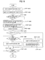
- Fig. 19 is a flowchart illustrating an operation of high-speed split processing according to the fourth embodiment of the present invention, and this operation will be described below.
- the processing in the step 14070 and afterward is a processing for performing the remaining copy in the background (the copy processing having been performed before falling in the split status in order to have the same content between the original and copy volumes).
- the differential bitmaps P2 and S2 have their contents always matched.
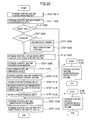
- Fig. 20 is a flowchart illustrating an operation to perform a write processing to the original volume when falling in a high-speed split status according to the fourth embodiment of the present invention, and this operation will be described below.
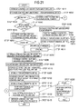
- Fig. 21 is a flowchart illustrating an operation to perform write processing to the copy volume when falling in the high-speed split status according to the fourth embodiment of the present invention, and this operation will be described below.
- the storage control unit 20B receives old data from the storage control unit 20A and transfers to the host 10 in the same way as above.
- the processing at a time when the original volume receives a write request to an unreflected region to the copy volume from the host 10 when falling in the above-described high-speed split status is called the "previous copy processing"
- the processing at a time when the copy volume receives from the host 10 a read/write request to an uncopied region from the original volume is called the "prefetch copy processing”.
- the fourth embodiment of the present invention realizes the prefetch copy processing, as a form of the to-be-written request from the copy volume to the original volume as described with reference to the flow of Fig. 21, so that a deadlock involved in the cache memory area assurance within the opposite-side storage control unit between the prefetch copy processing and the previous copy processing can be prevented.
- the processing among the high-speed Split, the previous copy and the prefetch copy can be performed by the processing having secured the lock of the data to-be-copied, and it becomes possible to perform exclusion control.
- the differential bitmap is switched from P1 to P2, the bitmap P2 is used to continue copying in the background, but the bitmap P2 is not used for the update of data, and it is made not to turn ON the bit of the bitmap P2. And, the opportunity to turn OFF the bit of the differential bitmap P1 is determined to be after the background copy, previous copy and prefetch copy complete copying the data to-be-copied from the original volume to the copy volume. Thus, a case that the bit of the differential bitmap P1 is unfavorably turned OFF can be excluded.
- the differential bitmap S2 can set all bits to "1" (ON) before the split so to exclude a case "the bit of the differential bitmap S2 is OFF, but the bit of the differential bitmap P2 is ON".
- a region where the differential bitmap P2 has not been copied to the differential bitmap S2 is judged to be necessary to perform a prefetch copy with reference to the differential bitmap S2, and the "to-be-written request" is performed, but when the differential bitmap P2 is referred to, there is a case that the copy is actually not necessary. In such a case, the bit of the differential bitmap S2 is turned OFF, and the request of the copy volume may be performed.
- the storage control unit 20A determines a frequency of sending depending on a response time for the cache memory assurance from the storage control unit 20B and performs sending. It is because the processing is in series from the storage control unit 20A to the storage control unit 20B, so that it is necessary to limit a flow rate of processing.
- the Resync processing in the fourth embodiment of the present invention can be performed in the same way as those in the first to third embodiments of the present invention.
- Fig. 22 is a diagram showing a data transfer path in case of a write request during the replication creation processing between different storage control units according to the fourth embodiment of the present invention. Fig. 22 also shows an arrangement of the differential bitmap.
- the reflection of the update to the copy volume when the write request is received can be performed on an extension of the same I/O processing in the same way as in the above-described first to third embodiments of the present invention.
- the write request for update to the copy volume in this case is sent from CPU 21A to CPU 21B through the same route as the data transmission line, and the differential bitmap at the time of merging of the differential bitmap is also sent through the same route as the data transmission line.
- Fig. 23 is a diagram showing a data transfer path in case of a write request during the replication creation processing between different storage control units in the second embodiment of the present invention shown in Fig. 2
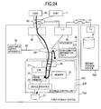
- Fig. 24 is a diagram showing a data transfer path in case of a write request during the replication creation processing between different storage control units in the third embodiment of the present invention shown in Fig. 3.
- the data transfer paths shown in Fig. 23 and Fig. 24 are different form that shown in Fig. 15 because the hardware has a different structure, but the other portions are not different from those in Fig. 15, and the write request for update to the copy volume is sent from the CPU 21A to the CPU 21B through the same route as the data transmission line.
- the write request for update to the copy volume is sent from the CPU 21A to the CPU 21B through the same route as the data transmission line in the same way as described with reference to Fig. 22.
- the differential bitmap at the time of merging the differential bitmap is also sent through the same route as the data transmission line.
Applications Claiming Priority (2)
| Application Number | Priority Date | Filing Date | Title |
|---|---|---|---|
| JP2004115693 | 2004-04-09 | ||
| JP2004115693A JP2005301590A (ja) | 2004-04-09 | 2004-04-09 | ストレージシステム及びデータ複製方法 |
Publications (2)
| Publication Number | Publication Date |
|---|---|
| EP1591899A2 true EP1591899A2 (fr) | 2005-11-02 |
| EP1591899A3 EP1591899A3 (fr) | 2011-04-27 |
Family
ID=34934808
Family Applications (1)
| Application Number | Title | Priority Date | Filing Date |
|---|---|---|---|
| EP05007538A Withdrawn EP1591899A3 (fr) | 2004-04-09 | 2005-04-06 | Reproduction de données dans un système de stockage |
Country Status (3)
| Country | Link |
|---|---|
| US (3) | US7302535B2 (fr) |
| EP (1) | EP1591899A3 (fr) |
| JP (1) | JP2005301590A (fr) |
Cited By (4)
| Publication number | Priority date | Publication date | Assignee | Title |
|---|---|---|---|---|
| WO2007093499A1 (fr) | 2006-02-17 | 2007-08-23 | International Business Machines Corporation | Appareil, système et procédé de divulgation progressive d'informations |
| EP2148278A1 (fr) | 2008-07-02 | 2010-01-27 | Hitachi Ltd. | Système de stockage et procédé de récupération de copies à distance |
| US8028139B2 (en) | 2004-04-19 | 2011-09-27 | Hitachi, Ltd. | Remote copy method and remote copy system |
| US8364919B2 (en) | 2008-07-08 | 2013-01-29 | Hitachi, Ltd. | Remote copy system and method |
Families Citing this family (55)
| Publication number | Priority date | Publication date | Assignee | Title |
|---|---|---|---|---|
| JP4454342B2 (ja) * | 2004-03-02 | 2010-04-21 | 株式会社日立製作所 | ストレージシステム及びストレージシステムの制御方法 |
| JP2005301590A (ja) | 2004-04-09 | 2005-10-27 | Hitachi Ltd | ストレージシステム及びデータ複製方法 |
| US20060095483A1 (en) * | 2004-04-23 | 2006-05-04 | Waratek Pty Limited | Modified computer architecture with finalization of objects |
| US7844665B2 (en) | 2004-04-23 | 2010-11-30 | Waratek Pty Ltd. | Modified computer architecture having coordinated deletion of corresponding replicated memory locations among plural computers |
| US8028299B2 (en) * | 2005-04-21 | 2011-09-27 | Waratek Pty, Ltd. | Computer architecture and method of operation for multi-computer distributed processing with finalization of objects |
| US8239477B2 (en) * | 2005-07-08 | 2012-08-07 | Cisco Technology, Inc. | Apparatus and methods for controlling a data tapping session in a storage area network |
| US7702851B2 (en) * | 2005-09-20 | 2010-04-20 | Hitachi, Ltd. | Logical volume transfer method and storage network system |
| JP4550717B2 (ja) | 2005-10-28 | 2010-09-22 | 富士通株式会社 | 仮想ストレージシステム制御装置、仮想ストレージシステム制御プログラム、仮想ストレージシステム制御方法 |
| JP4436316B2 (ja) * | 2005-12-27 | 2010-03-24 | 富士通株式会社 | ビットマップ処理方式 |
| US20070174539A1 (en) * | 2005-12-30 | 2007-07-26 | Hidehisa Shitomi | System and method for restricting the number of object copies in an object based storage system |
| US7809892B1 (en) | 2006-04-03 | 2010-10-05 | American Megatrends Inc. | Asynchronous data replication |
| JP5105856B2 (ja) * | 2006-12-20 | 2012-12-26 | Necシステムテクノロジー株式会社 | ストレージシステム、論理ボリュームのレプリケーション方法・プログラム |
| US8046547B1 (en) | 2007-01-30 | 2011-10-25 | American Megatrends, Inc. | Storage system snapshots for continuous file protection |
| US20080209145A1 (en) * | 2007-02-27 | 2008-08-28 | Shyamsundar Ranganathan | Techniques for asynchronous data replication |
| JP2008234030A (ja) * | 2007-03-16 | 2008-10-02 | Hitachi Ltd | コピーシステム及びコピー方法 |
| US8082407B1 (en) | 2007-04-17 | 2011-12-20 | American Megatrends, Inc. | Writable snapshots for boot consolidation |
| US7818522B2 (en) * | 2007-09-07 | 2010-10-19 | International Business Machines Corporation | Apparatus, system, and method for incremental resynchronization in a data storage system |
| US8065442B1 (en) | 2007-11-19 | 2011-11-22 | American Megatrends, Inc. | High performance journaling for replication and continuous data protection |
| US8230185B2 (en) | 2008-10-08 | 2012-07-24 | International Business Machines Corporation | Method for optimizing cleaning of maps in FlashCopy cascades containing incremental maps |
| US8332354B1 (en) | 2008-12-15 | 2012-12-11 | American Megatrends, Inc. | Asynchronous replication by tracking recovery point objective |
| JP4615595B2 (ja) * | 2008-12-22 | 2011-01-19 | 富士通株式会社 | ストレージスイッチ、ストレージシステム、データコピー方法 |
| JP4832553B2 (ja) | 2009-06-16 | 2011-12-07 | 株式会社日立製作所 | コピー開始タイミングを制御するシステム及び方法 |
| US8386731B2 (en) * | 2009-09-14 | 2013-02-26 | Vmware, Inc. | Method and system for optimizing live migration of persistent data of virtual machine using disk I/O heuristics |
| US8849750B2 (en) * | 2010-10-13 | 2014-09-30 | International Business Machines Corporation | Synchronization for initialization of a remote mirror storage facility |
| JP5740196B2 (ja) * | 2011-04-18 | 2015-06-24 | 株式会社東芝 | データベース装置およびデータベース再編成方法 |
| US9063835B2 (en) | 2011-06-02 | 2015-06-23 | Hewlett-Packard Development Company, L.P. | Managing processing of user requests and data replication for a mass storage system |
| JP5712851B2 (ja) * | 2011-07-29 | 2015-05-07 | 富士通株式会社 | データ分割装置、データ分割方法およびデータ分割プログラム |
| CN103377130A (zh) * | 2012-04-13 | 2013-10-30 | 日立(中国)研究开发有限公司 | 数据存储设备以及相应的数据存储方法 |
| CN103885717B (zh) * | 2012-12-19 | 2016-10-12 | 杭州宏杉科技有限公司 | 一种数据复制方法及装置 |
| US9178903B1 (en) * | 2014-12-02 | 2015-11-03 | Synack, Inc. | Simulating a bot-net spanning a plurality of geographic regions |
| CN106326030B (zh) * | 2015-06-26 | 2020-03-20 | 伊姆西Ip控股有限责任公司 | 用于存储系统中的软切换的方法和装置 |
| CN106897231B (zh) * | 2017-02-28 | 2021-01-12 | 苏州浪潮智能科技有限公司 | 一种基于高性能存储介质的数据缓存方法及系统 |
| KR102426107B1 (ko) * | 2017-12-20 | 2022-07-28 | 에스케이하이닉스 주식회사 | 메모리 시스템 및 그것의 동작 방법 |
| US11042451B2 (en) * | 2018-12-14 | 2021-06-22 | International Business Machines Corporation | Restoring data lost from battery-backed cache |
| US11522799B1 (en) | 2020-06-30 | 2022-12-06 | Amazon Technologies, Inc. | Dynamically managed data traffic workflows |
| US11714732B1 (en) * | 2020-09-30 | 2023-08-01 | Amazon Technologies, Inc. | Granular tracking of replication consistency using subsets of asynchronous replication tasks |
| US11675665B2 (en) | 2020-12-09 | 2023-06-13 | Dell Products L.P. | System and method for backup generation using composed systems |
| US11693703B2 (en) | 2020-12-09 | 2023-07-04 | Dell Products L.P. | Monitoring resource utilization via intercepting bare metal communications between resources |
| US11675625B2 (en) | 2020-12-09 | 2023-06-13 | Dell Products L.P. | Thin provisioning of resources using SCPS and a bidding system |
| US11809911B2 (en) | 2020-12-09 | 2023-11-07 | Dell Products L.P. | Resuming workload execution in composed information handling system |
| US11809912B2 (en) | 2020-12-09 | 2023-11-07 | Dell Products L.P. | System and method for allocating resources to perform workloads |
| US11853782B2 (en) | 2020-12-09 | 2023-12-26 | Dell Products L.P. | Method and system for composing systems using resource sets |
| US11704159B2 (en) | 2020-12-09 | 2023-07-18 | Dell Products L.P. | System and method for unified infrastructure architecture |
| US11698821B2 (en) | 2020-12-09 | 2023-07-11 | Dell Products L.P. | Composable information handling systems in an open network using access control managers |
| US11604595B2 (en) * | 2020-12-09 | 2023-03-14 | Dell Products L.P. | Data mirroring and data migration between storage volumes using system control processors |
| US11934875B2 (en) | 2020-12-09 | 2024-03-19 | Dell Products L.P. | Method and system for maintaining composed systems |
| US11928515B2 (en) | 2020-12-09 | 2024-03-12 | Dell Products L.P. | System and method for managing resource allocations in composed systems |
| US11675916B2 (en) | 2021-01-28 | 2023-06-13 | Dell Products L.P. | Method and system for limiting data accessibility in composed systems |
| US11797341B2 (en) | 2021-01-28 | 2023-10-24 | Dell Products L.P. | System and method for performing remediation action during operation analysis |
| US11768612B2 (en) | 2021-01-28 | 2023-09-26 | Dell Products L.P. | System and method for distributed deduplication in a composed system |
| US11687280B2 (en) | 2021-01-28 | 2023-06-27 | Dell Products L.P. | Method and system for efficient servicing of storage access requests |
| CN113284039B (zh) * | 2021-07-16 | 2021-10-08 | 杭州安恒信息技术股份有限公司 | 一种位图管理方法、装置、设备及可读存储介质 |
| US11947697B2 (en) | 2021-07-22 | 2024-04-02 | Dell Products L.P. | Method and system to place resources in a known state to be used in a composed information handling system |
| US11928506B2 (en) | 2021-07-28 | 2024-03-12 | Dell Products L.P. | Managing composition service entities with complex networks |
| US20230236755A1 (en) * | 2022-01-27 | 2023-07-27 | Pure Storage, Inc. | Data Resiliency Using Container Storage System Storage Pools |
Citations (1)
| Publication number | Priority date | Publication date | Assignee | Title |
|---|---|---|---|---|
| EP0939371A2 (fr) | 1998-02-26 | 1999-09-01 | Hitachi, Ltd. | Sous-ensemble de mémoire et méthode de réorganiser des données multiplexées |
Family Cites Families (47)
| Publication number | Priority date | Publication date | Assignee | Title |
|---|---|---|---|---|
| US124139A (en) * | 1872-02-27 | Improvement in imitation buttons | ||
| US4785415A (en) | 1986-08-29 | 1988-11-15 | Hewlett-Packard Company | Digital data buffer and variable shift register |
| US5210866A (en) | 1990-09-12 | 1993-05-11 | Storage Technology Corporation | Incremental disk backup system for a dynamically mapped data storage subsystem |
| US5544347A (en) * | 1990-09-24 | 1996-08-06 | Emc Corporation | Data storage system controlled remote data mirroring with respectively maintained data indices |
| US5459857A (en) | 1992-05-15 | 1995-10-17 | Storage Technology Corporation | Fault tolerant disk array data storage subsystem |
| US5403639A (en) | 1992-09-02 | 1995-04-04 | Storage Technology Corporation | File server having snapshot application data groups |
| JP3431972B2 (ja) | 1993-11-29 | 2003-07-28 | 株式会社日立製作所 | 仮想ディスクシステム |
| DE69420363T2 (de) | 1993-12-03 | 2000-05-11 | Hitachi Ltd | Speichervorrichtung |
| JPH07210439A (ja) | 1993-12-03 | 1995-08-11 | Hitachi Ltd | 記憶装置 |
| US6073218A (en) * | 1996-12-23 | 2000-06-06 | Lsi Logic Corp. | Methods and apparatus for coordinating shared multiple raid controller access to common storage devices |
| US6073209A (en) | 1997-03-31 | 2000-06-06 | Ark Research Corporation | Data storage controller providing multiple hosts with access to multiple storage subsystems |
| US6131148A (en) | 1998-01-26 | 2000-10-10 | International Business Machines Corporation | Snapshot copy of a secondary volume of a PPRC pair |
| JPH11212932A (ja) | 1998-01-28 | 1999-08-06 | Oki Electric Ind Co Ltd | ネットワーク資源管理システム |
| US6567774B1 (en) | 1998-01-30 | 2003-05-20 | Compaq Computer Corporation | Method and system for configuring and updating networked client stations using a virtual disk and a snapshot disk |
| JP4689137B2 (ja) | 2001-08-08 | 2011-05-25 | 株式会社日立製作所 | リモートコピー制御方法、及びストレージシステム |
| US6449607B1 (en) * | 1998-09-11 | 2002-09-10 | Hitachi, Ltd. | Disk storage with modifiable data management function |
| US6691208B2 (en) | 1999-03-12 | 2004-02-10 | Diva Systems Corp. | Queuing architecture including a plurality of queues and associated method for controlling admission for disk access requests for video content |
| EP1039387B1 (fr) * | 1999-03-19 | 2010-05-19 | Hitachi, Ltd. | Système pour la replication de données |
| JP2000339104A (ja) | 1999-03-19 | 2000-12-08 | Hitachi Ltd | ディスクサブシステム及びデータ複写方法。 |
| JP2001014112A (ja) | 1999-06-29 | 2001-01-19 | Hitachi Ltd | ディスクサブシステム及びリモートコピー方法 |
| US6341341B1 (en) | 1999-12-16 | 2002-01-22 | Adaptec, Inc. | System and method for disk control with snapshot feature including read-write snapshot half |
| US6647514B1 (en) | 2000-03-23 | 2003-11-11 | Hewlett-Packard Development Company, L.P. | Host I/O performance and availability of a storage array during rebuild by prioritizing I/O request |
| JP2001318833A (ja) | 2000-05-09 | 2001-11-16 | Hitachi Ltd | ボリューム複製機能を有する記憶装置サブシステム、および、それを用いたコンピュータシステム |
| JP2002007304A (ja) | 2000-06-23 | 2002-01-11 | Hitachi Ltd | ストレージエリアネットワークを用いた計算機システム及びそのデータ取り扱い方法 |
| US6618794B1 (en) * | 2000-10-31 | 2003-09-09 | Hewlett-Packard Development Company, L.P. | System for generating a point-in-time copy of data in a data storage system |
| JP2002189570A (ja) | 2000-12-20 | 2002-07-05 | Hitachi Ltd | 記憶システムの二重化方法および記憶システム |
| KR100388498B1 (ko) | 2000-12-30 | 2003-06-25 | 한국전자통신연구원 | 복수 개의 레이드를 구비한 계층적 레이드 시스템 |
| US6606690B2 (en) | 2001-02-20 | 2003-08-12 | Hewlett-Packard Development Company, L.P. | System and method for accessing a storage area network as network attached storage |
| US6510500B2 (en) | 2001-03-09 | 2003-01-21 | International Business Machines Corporation | System and method for minimizing message transactions for fault-tolerant snapshots in a dual-controller environment |
| JP3987295B2 (ja) | 2001-03-19 | 2007-10-03 | 株式会社東芝 | 処理最適化方法、コンピュータ、及び記憶装置 |
| JP3714184B2 (ja) * | 2001-03-29 | 2005-11-09 | 富士通株式会社 | 記憶装置のデータ領域間複写処理方法、及び記憶システム |
| US6728849B2 (en) * | 2001-12-14 | 2004-04-27 | Hitachi, Ltd. | Remote storage system and method |
| JP2003131818A (ja) | 2001-10-25 | 2003-05-09 | Hitachi Ltd | クラスタ構成ストレージにおけるクラスタ間raid構成 |
| JP3730907B2 (ja) | 2001-12-04 | 2006-01-05 | 日本電気株式会社 | ディスクアレイ装置間の遠隔データコピー方式 |
| US7152078B2 (en) * | 2001-12-27 | 2006-12-19 | Hitachi, Ltd. | Systems, methods and computer program products for backup and restoring storage volumes in a storage area network |
| JP2003202964A (ja) | 2002-01-09 | 2003-07-18 | Hitachi Ltd | 計算機システムの制御方法、計算機システム、記憶装置の制御方法及び記憶装置 |
| US20030129214A1 (en) * | 2002-01-10 | 2003-07-10 | University Of Washington | Methods of enhancing the biocompatibility of an implantable medical device |
| JP4154893B2 (ja) | 2002-01-23 | 2008-09-24 | 株式会社日立製作所 | ネットワークストレージ仮想化方法 |
| JP4170056B2 (ja) | 2002-03-29 | 2008-10-22 | 株式会社日立製作所 | 複製ボリューム間でのバックアップ・リストア管理方法およびこの方法に用いる記憶制御装置 |
| US6820180B2 (en) | 2002-04-04 | 2004-11-16 | International Business Machines Corporation | Apparatus and method of cascading backup logical volume mirrors |
| JP2003316616A (ja) | 2002-04-24 | 2003-11-07 | Hitachi Ltd | 計算機システム |
| US6977654B2 (en) | 2002-10-30 | 2005-12-20 | Iviz, Inc. | Data visualization with animated speedometer dial charts |
| US7124128B2 (en) * | 2003-06-17 | 2006-10-17 | International Business Machines Corporation | Method, system, and program for managing requests to tracks subject to a relationship |
| US20050063216A1 (en) * | 2003-09-24 | 2005-03-24 | Wilkins Virgil V. | System and method for providing efficient redundancy mirroring communications in an n-way scalable network storage system |
| JP2005157867A (ja) | 2003-11-27 | 2005-06-16 | Hitachi Ltd | 記憶システム、記憶制御装置及び記憶制御装置を用いたデータ中継方法 |
| JP4703959B2 (ja) | 2003-12-03 | 2011-06-15 | 株式会社日立製作所 | 記憶装置システムおよびそのレプリケーション作成方法 |
| JP2005301590A (ja) | 2004-04-09 | 2005-10-27 | Hitachi Ltd | ストレージシステム及びデータ複製方法 |
-
2004
- 2004-04-09 JP JP2004115693A patent/JP2005301590A/ja active Pending
- 2004-06-30 US US10/879,471 patent/US7302535B2/en not_active Expired - Fee Related
-
2005
- 2005-04-06 EP EP05007538A patent/EP1591899A3/fr not_active Withdrawn
-
2007
- 2007-10-17 US US11/907,748 patent/US7689792B2/en not_active Expired - Fee Related
-
2010
- 2010-03-03 US US12/716,308 patent/US7908449B2/en not_active Expired - Fee Related
Patent Citations (1)
| Publication number | Priority date | Publication date | Assignee | Title |
|---|---|---|---|---|
| EP0939371A2 (fr) | 1998-02-26 | 1999-09-01 | Hitachi, Ltd. | Sous-ensemble de mémoire et méthode de réorganiser des données multiplexées |
Cited By (11)
| Publication number | Priority date | Publication date | Assignee | Title |
|---|---|---|---|---|
| US8234471B2 (en) | 2003-06-27 | 2012-07-31 | Hitachi, Ltd. | Remote copy method and remote copy system |
| US9058305B2 (en) | 2003-06-27 | 2015-06-16 | Hitachi, Ltd. | Remote copy method and remote copy system |
| US8028139B2 (en) | 2004-04-19 | 2011-09-27 | Hitachi, Ltd. | Remote copy method and remote copy system |
| WO2007093499A1 (fr) | 2006-02-17 | 2007-08-23 | International Business Machines Corporation | Appareil, système et procédé de divulgation progressive d'informations |
| EP2148278A1 (fr) | 2008-07-02 | 2010-01-27 | Hitachi Ltd. | Système de stockage et procédé de récupération de copies à distance |
| US7996637B2 (en) | 2008-07-02 | 2011-08-09 | Hitachi, Ltd. | Storage system and remote copy recovery method |
| US8117411B2 (en) | 2008-07-02 | 2012-02-14 | Hitachi, Ltd. | Storage system and remote copy recovery method |
| US8296537B2 (en) | 2008-07-02 | 2012-10-23 | Hitachi, Ltd. | Storage system and remote copy recovery method |
| US8452933B2 (en) | 2008-07-02 | 2013-05-28 | Hitachi, Ltd. | Storage system and remote copy recovery method |
| US8364919B2 (en) | 2008-07-08 | 2013-01-29 | Hitachi, Ltd. | Remote copy system and method |
| US8732420B2 (en) | 2008-07-08 | 2014-05-20 | Hitachi, Ltd. | Remote copy system and method |
Also Published As
| Publication number | Publication date |
|---|---|
| JP2005301590A (ja) | 2005-10-27 |
| US7689792B2 (en) | 2010-03-30 |
| US20050228957A1 (en) | 2005-10-13 |
| US20100161900A1 (en) | 2010-06-24 |
| US20080052480A1 (en) | 2008-02-28 |
| EP1591899A3 (fr) | 2011-04-27 |
| US7908449B2 (en) | 2011-03-15 |
| US7302535B2 (en) | 2007-11-27 |
Similar Documents
| Publication | Publication Date | Title |
|---|---|---|
| US7302535B2 (en) | Data replication in a storage system | |
| US9753663B1 (en) | Triangular asynchronous replication | |
| US7228398B2 (en) | Multi-site remote-copy system | |
| US7496718B2 (en) | Data transfer and access control between disk array systems | |
| US7464236B2 (en) | Storage system and storage management method | |
| US9268658B2 (en) | Failover to backup site in connection with triangular asynchronous replication | |
| US7380082B2 (en) | Reading virtual ordered writes at local storage device | |
| US7647525B2 (en) | Resumption of operations following failover in connection with triangular asynchronous replication | |
| US7430646B2 (en) | Planned switchover in connection with triangular asynchronous replication | |
| US7779291B2 (en) | Four site triangular asynchronous replication | |
| US7421550B2 (en) | Storage system and storage system management method | |
| US20070113034A1 (en) | Storage remote copy system | |
| US7809907B2 (en) | System and method for backup by splitting a copy pair and storing a snapshot | |
| US7752404B2 (en) | Toggling between concurrent and cascaded triangular asynchronous replication | |
| US20070234105A1 (en) | Failover to asynchronous backup site in connection with triangular asynchronous replication | |
| US7069400B2 (en) | Data processing system | |
| US20110167044A1 (en) | Computing system and backup method using the same | |
| US20110196825A1 (en) | Storage system and data duplication method in the same |
Legal Events
| Date | Code | Title | Description |
|---|---|---|---|
| PUAI | Public reference made under article 153(3) epc to a published international application that has entered the european phase |
Free format text: ORIGINAL CODE: 0009012 |
|
| AK | Designated contracting states |
Kind code of ref document: A2 Designated state(s): AT BE BG CH CY CZ DE DK EE ES FI FR GB GR HU IE IS IT LI LT LU MC NL PL PT RO SE SI SK TR |
|
| AX | Request for extension of the european patent |
Extension state: AL BA HR LV MK YU |
|
| 17P | Request for examination filed |
Effective date: 20090623 |
|
| PUAL | Search report despatched |
Free format text: ORIGINAL CODE: 0009013 |
|
| AK | Designated contracting states |
Kind code of ref document: A3 Designated state(s): AT BE BG CH CY CZ DE DK EE ES FI FR GB GR HU IE IS IT LI LT LU MC NL PL PT RO SE SI SK TR |
|
| AX | Request for extension of the european patent |
Extension state: AL BA HR LV MK YU |
|
| RIC1 | Information provided on ipc code assigned before grant |
Ipc: G06F 12/16 20060101ALI20110324BHEP Ipc: G06F 11/20 20060101AFI20110324BHEP |
|
| AKX | Designation fees paid |
Designated state(s): DE FR GB IE |
|
| 17Q | First examination report despatched |
Effective date: 20120601 |
|
| STAA | Information on the status of an ep patent application or granted ep patent |
Free format text: STATUS: THE APPLICATION HAS BEEN WITHDRAWN |
|
| 18W | Application withdrawn |
Effective date: 20140731 |