EP1591175B1 - Bending device with cutting mechanism - Google Patents
Bending device with cutting mechanism Download PDFInfo
- Publication number
- EP1591175B1 EP1591175B1 EP05009362A EP05009362A EP1591175B1 EP 1591175 B1 EP1591175 B1 EP 1591175B1 EP 05009362 A EP05009362 A EP 05009362A EP 05009362 A EP05009362 A EP 05009362A EP 1591175 B1 EP1591175 B1 EP 1591175B1
- Authority
- EP
- European Patent Office
- Prior art keywords
- bending
- workpiece
- die
- cutting
- cutter
- Prior art date
- Legal status (The legal status is an assumption and is not a legal conclusion. Google has not performed a legal analysis and makes no representation as to the accuracy of the status listed.)
- Expired - Fee Related
Links
- 238000005452 bending Methods 0.000 title claims description 179
- 238000005520 cutting process Methods 0.000 title claims description 85
- 230000007246 mechanism Effects 0.000 title claims description 70
- 238000000034 method Methods 0.000 description 12
- 238000004519 manufacturing process Methods 0.000 description 4
- 238000010586 diagram Methods 0.000 description 1
- 238000012986 modification Methods 0.000 description 1
- 230000004048 modification Effects 0.000 description 1
Images


Classifications
-
- B—PERFORMING OPERATIONS; TRANSPORTING
- B21—MECHANICAL METAL-WORKING WITHOUT ESSENTIALLY REMOVING MATERIAL; PUNCHING METAL
- B21D—WORKING OR PROCESSING OF SHEET METAL OR METAL TUBES, RODS OR PROFILES WITHOUT ESSENTIALLY REMOVING MATERIAL; PUNCHING METAL
- B21D7/00—Bending rods, profiles, or tubes
- B21D7/02—Bending rods, profiles, or tubes over a stationary forming member; by use of a swinging forming member or abutment
- B21D7/024—Bending rods, profiles, or tubes over a stationary forming member; by use of a swinging forming member or abutment by a swinging forming member
-
- E—FIXED CONSTRUCTIONS
- E01—CONSTRUCTION OF ROADS, RAILWAYS, OR BRIDGES
- E01D—CONSTRUCTION OF BRIDGES, ELEVATED ROADWAYS OR VIADUCTS; ASSEMBLY OF BRIDGES
- E01D19/00—Structural or constructional details of bridges
- E01D19/06—Arrangement, construction or bridging of expansion joints
-
- E—FIXED CONSTRUCTIONS
- E01—CONSTRUCTION OF ROADS, RAILWAYS, OR BRIDGES
- E01D—CONSTRUCTION OF BRIDGES, ELEVATED ROADWAYS OR VIADUCTS; ASSEMBLY OF BRIDGES
- E01D19/00—Structural or constructional details of bridges
- E01D19/08—Damp-proof or other insulating layers; Drainage arrangements or devices ; Bridge deck surfacings
- E01D19/083—Waterproofing of bridge decks; Other insulations for bridges, e.g. thermal ; Bridge deck surfacings
Definitions
- This invention relates to a bending device with a cutting mechanism for bending and cutting a workpiece, such as a pipe, as described in the first part of claim 1 and disclosed in US-A-5 927 124 ..
- a conventionally known bending device is provided with a bending die corresponding with a shape of bending, a clamping die facing the bending die, a wiper die disposed proximate to the bending die, and a pressure die facing the wiper die.
- the conventional bending device clamps a workpiece with the bending die and the clamping die, holds the workpiece with the wiper die and the pressure die, and bends the workpiece corresponding to rotation of the bending die.
- An exhaust manifold for example, is one of the automobile parts for which this type of bending device is used for bending.
- a pipe for an exhaust manifold is manufactured with several times of bending. In a bending process, it is necessary to provide the pipes with a clamping portion which is approximately 10cm in length in order to clamp the pipes.
- the clamping portion provided on an end of a workpiece is linear, this portion needs to be cut if the clamping portion is longer than a desired length.
- suitable length for a clamping portion can be occasionally achieved by cutting the clamping portion into half on a connection portion between the two parts. In this case, it is not preferable to replace a workpiece on a separate cutting device from the bending device in order to conduct cutting on the workpiece, because the number of process steps increases.
- One of the objects of the present invention is to provide a bending device with a cutting mechanism wherein efficient bending and cutting can be conducted on a workpiece.
- the present invention provides a bending device having the features of claim 1.
- the bending device with a cutting mechanism of the present invention can conduct cutting on a workpiece as well as bending. Hence, this device of the present invention is capable of effective manufacturing of products.
- the above-described bending device with a cutting mechanism preferably comprises: an input unit to input bending information, including information on the target number of manufactured items to be made from one workpiece; and a cutting position calculation unit that calculates a cutting position of a workpiece.
- the bending device with a cutting mechanism may comprise a cutting control unit that controls cutting by the cutter so that cutting is conducted as least after a first bending for a second item.
- the cutting control unit may be constituted to automatically control the position of the cutter depending at least on a bending position and a bending angle.
- the bending device with a cutting mechanism comprises: a chuck mechanism that holds a workpiece; and a feeding mechanism that feeds a workpiece held by the chuck mechanism in a longitudinal direction, and moves in a direction perpendicular to the longitudinal direction of the workpiece.
- the bending device with a cutting mechanism with plurality of bending dies tiered on top of another, and to constitute the above-described feeding mechanism so as to place a workpiece at a position corresponding to a position of one of the tiered bending dies.
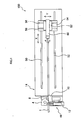
- a bending device with a cutting mechanism 100 of the present embodiment comprises a device main body 14 having one pair of rails 50, 52 laid in parallel to a longitudinal direction of a workpiece 1.
- a carriage 54 is movably engaged with the rails 50, 52.
- the carriage 54 has one pair of rails 56, 58 laid in parallel to each other in a direction perpendicular to the workpiece 1.
- a carrying base 62 having a chuck mechanism 60 is movably engaged.
- the carrying base 62 is constituted to be able to move the chuck mechanism 60, by means of driving motors 116a to 116c to be described later, in a longitudinal direction of the workpiece 1 (X direction), in a horizontal direction (Y direction) perpendicular to the longitudinal direction of the workpiece 1, and in a vertical direction (Z direction shown in Fig. 3 ) perpendicular to both the longitudinal direction (X direction) and the horizontal direction (Y direction) of the workpiece 1.
- the chuck mechanism 60 is constituted so as to be able to hold a rear end of the workpiece 1, and to twist the workpiece 1 around a center of the workpiece 1 in the longitudinal direction while holding.
- driving motors 116a to 116c can be replaced with hydraulic cylinders.
- the chuck mechanism 60 holds the rear end of the workpiece 1, and moves in the X, Y and Z directions. Corresponding to the moving direction of the chuck mechanism 60, the workpiece 1 can be fed in any of these directions.
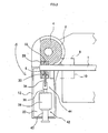
- a bending die 4 is disposed on a rear end of the bending device with a cutting mechanism 100.
- a clamping die 6 is also provided thereon facing the bending die 4.
- the bending die 4 is provided with a bending groove 2 corresponding to the contour of the workpiece 1 to form a target bending shape. It is shown with a chain double-dashed line in Fig. 2 that a wiper die 8 is provided adjacent to the bending die 4, and that a pressure die 10 is provided facing the wiper die 8.
- the pressure die 10 is constituted to be able to move, by a hydraulic cylinder or a motor not shown in the drawing, toward the workpiece 1, and to hold the workpiece 1 together with the wiper die 8. It should be noted that the wiper die 8 and pressure die 10 can be provided if necessary.
- the bending die 4 is attached to a bending arm 12.
- the bending arm 12 is supported by the device main body 14 to be rotateble via a driving shaft 16 around an axis C.
- the bending arm 12 is driven to rotate on the driving shaft 16 (axis C) by a bending drive mechanism 18 provided on the device main body 14.
- the bending drive mechanism 18 rotates the bending arm 12 around the driving shaft 16 by rotating the driving shaft 16 by a hydraulic cylinder or a link mechanism not shown in the drawing.
- a hydraulic motor or an electric motor can be used to rotate the driving shaft 16 instead of the above-described hydraulic cylinder.
- a clamping platform 20 is swingablly supported by a driving link 22 and a driven link 24.
- a parallel link is formed by the driving link 22 and the driven link 24.
- a rod of a hydraulic cylinder 26 swingablly supported by the bending arm 12 is connected to the driving link 22.
- the clamping die 6 is attached on the clamping platform 20.
- the clamping platform 20 is moved by driving the hydraulic cylinder 26 in the direction of Arrow A
- the clamping die 6 moves toward the bending die 4.
- the clamping die 6 moves in a direction to be away from the bending die 4.
- the clamping die 6 has a groove 6a formed to be corresponding to the contour of the workpiece 1.
- Facing the clamping die 6, a fastening die 28 is integrally attached to the bending die 4.
- the fastening die 28 has a groove 28a formed to be corresponding to the contour of the workpiece 1.
- the groove 6a of the clamping die 6 and the groove 28a of the fastening die 28 are both formed linearly along the axial direction of the workpiece 1.
- the groove 28a of the fastening die 28 is connected to the bending groove 2 of the bending die 4. It should be noted that the grooves 6a and 28a can be formed in a curved shape depending on a desired bending shape.
- the clamping die 6 and the fastening die 28 have enough lengths to be able to provide holding force for wrapping the workpiece 1 around the bending groove 2 of the bending die 4 without the workpiece 1 being removed from the clamping die 6 and the fastening die 28 when the workpiece 1 is clamped by the clamping die 6 and the fastening die 28, and the bending arm 12 is rotated on the driving shaft 16 for bending the workpiece 1.
- the clamping die 6 has a groove 30 extending in a direction perpendicular to the axial direction of the workpiece 1.
- the fastening die 28 also has a groove 32 formed in the same shape as the groove 30 and disposed in an extension of the groove 30.
- a disk cutter 34 is inserted slidably. As shown in Fig. 3 , the cutter 34 is formed in a pointed shape wherein the center of the leading end is protruding, and disposed in a way so that the leading end strikes the center of the workpiece 1.
- the cutter 34 is formed to have a length larger than the diameter of the workpiece 1, so that the workpiece 1 can be cut when the cutter 34 is pressed against the workpiece 1 in normal line direction .
- the cutter 34 is fixed to the leading end of a sliding member 36.
- the sliding member 36 is guided by a guide member 38 attached on the clamping platform 20, and slides in a direction orthogonal to the axial direction of the workpiece 1.
- the sliding member 36 is slid by a hydraulic cylinder 40 attached to the guide member 38. In other words, the workpiece 1 can be cut by pushing the sliding member 36 with the hydraulic cylinder 40 toward the workpiece 1.
- the sliding member 36, guide member 38 and cylinder 40 constitute a cutting drive mechanism 42.
- the cutter 34 and the cutting drive mechanism 42 constitute a cutting mechanism 44.
- An electronic controller 150 of the bending device with a cutting mechanism 100 comprises: CPU 102 that controls operation of various mechanisms; ROM 104 that stores programs to execute bending and cutting; and RAM 106 that conducts various calculation processes and stores data. These units 102, 104 and 106 are all connected to an input/output port 108,
- the CPU 102 inputs signals from position sensors 110a to 110g via the input/output port 108.
- the position sensor 110a is used in order to detect the rotational angle position of the driving shaft 16 included in the bending drive mechanism 18, that is the rotational angles of the bending die 4 and the bending arm 12.
- the position sensor 110a is constituted with an encoder.
- the position sensor 110b detects the leading end and the rear end of the clamping die 6 which moves toward the bending die 4 and away from the bending die 4 when bending on the workpiece 1 is in process.
- the position sensor 110c detects the leading end and rear end of the clamping die 6 which moves toward the workpiece 1 and away from the workpiece 1 when bending on the workpiece is in process.
- the position sensors 110b and 110c are respectively constituted with limit switches.
- the position sensor 110d detects the position of the cutter 34 included in the cutting mechanism 44, and is constituted with an encoder.
- the position sensor 110e detects the position of the carriage 54 (the chuck mechanism 60) in X direction by detecting rotation of the motor 116a.
- the position sensor 110f detects the position of the chuck mechanism 60 in Y direction by detecting rotation of the motor 116b.
- the position sensor 110g detects the position of the chuck mechanism 60 in Z direction by detecting rotation of the motor 116c.
- the position sensors 110e to 110g are respectively constituted with an encoder.
- the CPU 102 outputs control signals via the input/output port 108 and drive circuits 112a to 112g based on data from the sensors 110a to 110g and memory data stored in the ROM 104 and RAM 106, and controls each driving system of the bending device with a cutting mechanism 100.
- a servo valve 114a shown in Fig. 4 controls hydraulic pressure given to the hydraulic cylinder included in the bending drive mechanism 18.
- a servo valve 114b controls hydraulic pressure given to the hydraulic cylinder 26 that actuates the clamping die 6.
- the servo valve 114c controls hydraulic pressure given to the hydraulic cylinder that actuates the pressure die 10.
- the serve valve 114d controls hydraulic pressure given to the hydraulic cylinder 40 included in the cutting mechanism 44.
- a keyboard 120 for inputting bending information and a display 130 that shows inputted information thereon are furthermore connected.
- the CPU 102 executes initialization in order set the bending device with a cutting mechanism 100 in a operatable state.
- the bending information includes the shape of a workpiece, the material of the workpiece, bending position, bending direction, bending angle, and the number of manufactured items to be made from a workpiece.
- necessary data for actual bending are calculated based on the inputted bending information.
- the following data can be, for example, calculated: clamping pressure for clamping a workpiece 1, distance and timing for moving the workpiece 1 in X, Y and Z directions, a rotational angle (bending angle) and timing of the bending die 4, timing for relieving clamping on the workpiece 1, and a twisting angle and timing for twisting the workpiece 1.
- a cutting position on the workpiece 1 is calculated based on the inputted bending information.
- the cutting position can be, for example, calculated depending on the number of manufactured items to be made from the workpiece 1.
- a workpiece 1 is placed in the groove 28a of the fastening die 28.
- the hydraulic cylinder 26 is driven to swing the driving link 22. Consequently, the clamping platform 20 is moved horizontally, and the clamping die 6 is moved toward the fastening die 28.
- the circumference of the workpiece 1 is clamped by the groove 28a of the fastening die 28 and the groove 6a of the clamping die 6.
- the workpiece 1 is held by the wiper die 8 and the pressure die 10.
- the bending drive mechanism 18 is driven to rotate the bending arm 12 around the driving shaft 16, and thereby to rotate the clamping die 6 around the bending die 4.
- the carriage 54 is moved in order to feed the workpiece 1 in X direction.
- bending on the workpiece 1 is conducted by the workpiece 1 being drawn out and wrapped around the bending groove 2 of the bending die 4.
- the workpiece 1 can be bent with a predetermined angle by rotating the bending arm 12 for predetermined angle.
- the cylinder 40 is driven to slide the sliding member 36 and to move the cutter 34 in the groove 30 toward the workpiece 1. Consequently, when the cutter 34 moves into the groove 32 of the fastening die 28 from the groove 30 of the clamping die 6, the workpiece 1 is cut by the cutter 34.
- the cylinder 40 is driven to move back the cutter 34, and the hydraulic cylinder 26 is driven to move the clamping die 6 away from the fastening die 28.
- the clamping on the workpiece 1 is therefore relieved.
- the bending arm 12 is rotated around the driving shaft 16 by the bending drive mechanism 18 to be replaced at an original position.
- the hydraulic cylinder 26 is once again driven to clamp the workpiece 1 by the clamping die 6 and the fastening die 28.
- the workpiece 1 can be twisted around the axial direction thereof, and then clamped.
- the bending arm 12 is rotated for predetermined angle by the bending drive mechanism 18 to conduct bending on the workpiece. 1.
- the cylinder 40 is driven to slide the sliding member 36 and cut the workpiece 1 by the cutter 34. Because of the cutting conducted on the workpiece 1 by the cutter 34, cutting of the workpiece 1 can be done simultaneously with completion of bending. Therefore, cutting can be conducted easily without removing a bent workpiece 1 from a bending device.
- the grooves 30 and 32 are formed respectively on the clamping die 6 and the fastening die 28, and the cutter 34 is inserted into the grooves 30 and 32, cutting can be easily and effectively conducted for manufacturing a product having a linear portion that is shorter than the widths of the clamping die 6 and the fastening die 28. Moreover, by having the cutter 34 in a pointed shape wherein the center of the leading end is protruding, the shape of the workpiece 1 can be preserved without being squashed.
- the present embodiment gives an example of bending wherein the workpiece 1 is pulled and bent with the bending device 100 having the fastening die 28 integrally constituted with the bending die 4, and the bending die 4 being rotated together with the bending arm 12.
- a way of bending is not limited to the above example. It is also possible to conduct bending on the a workpiece 1 by pushing and bending the workpiece 1 with a bending device wherein a bending die 4 formed virtually in a circular shape is fixed to a device main body 14, a fastening die 28 is provided on a bending arm 12, and a clamping die 6 and the fastening die 28 are rotated around a bending die 4 corresponding with rotation of the bending arm 12.
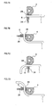
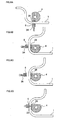
- Figs. 7A to 7D and Fig. 8A to 8D illustrate an example wherein a workpiece 1 is bent several times and cutting thereof is conducted.
- Fig. 7A the workpiece 1 is clamped by the clamping die 6 and the fastening die 28.
- Fig. 7B the bending arm 12 is rotated and the chuck mechanism 60 is moved in the longitudinal direction of the workpiece 1 to bend the workpiece 1 for 90 degree.
- Fig. 7C the bending arm 12 is replaced to the original position, and the workpiece 1 is fed by the chuck mechanism 60 in the longitudinal direction to twist the workpiece 1 for 180 degree.
- Fig. 7D the workpiece 1 is once again clamped by the clamping die 6 and the fastening die 28, and the bending arm 12 is rotated to bend the workpiece 1 for 90 degree.
- Fig. 8A the bending arm 12 is replaced to the original position, and the workpiece 1 is fed by the chuck mechanism 60 in the longitudinal direction.
- Fig. 8B the workpiece 1 is clamped by the clamping die 6 and the fastening die 28, and the bending arm 12 is rotated to bend the workpiece 1 for 90 degree.
- Fig. 8C while the clamping die 6 is positioned away from the fastening die 28, the chuck mechanism 60 is moved in parallel along the rails 56 and 58 so that the cutting portion on the workpiece 1 is moved to face the cutter 34.
- the cutter 34 is moved toward the workpiece 1 to conduct cutting. Consequently, the workpiece 1 can be cut in a required shape, and the workpiece 1 can be cut so as to have a linear portion shorter than the length of the clamping die 6 after bending.
- S51 bending is conducted.
- S52 it is determined whether or not bending has been completed up to a first bending for a second part. If bending for a first part has been completed but not the first bending for the second part (S52:NO), the process goes back to S51 and the first bending for the second part is conducted. If the first bending for the second part has been completed (S52:YES), the process proceeds to S53 to conduct cutting on the workpiece 1. Since the first bending for the second part has been done, it is not necessary to clamp the leading end of the second part with the bending die 4 and the clamping die 6. Therefore, the above-described problem can be inhibited.
- S60 it is determined whether or not the cutting direction by the cutter 34 is in the normal line direction in relation to the workpiece 1. For this determination, a sensor can be provided to detect direction of the cutter 34 at a cutting position. If the cutting direction is not in the normal line direction (S60:NO), the process goes to S70 to adjust the position and orientation of the cutter 34. Subsequently, the process proceeds to S80 and cutting process is conducted as described above.
- a plurality of bending dies tiered on top of another can be used for the bending die 4.
- bending and cutting can be conducted after placing a workpiece by a feeding mechanism to a position corresponding to the position of a desired bending die amongst the plurality of the tiered dies.
Applications Claiming Priority (2)
| Application Number | Priority Date | Filing Date | Title |
|---|---|---|---|
| JP2004135798A JP3861092B2 (ja) | 2004-04-30 | 2004-04-30 | 切断機構付曲げ加工装置 |
| JP2004135798 | 2004-04-30 |
Publications (2)
| Publication Number | Publication Date |
|---|---|
| EP1591175A1 EP1591175A1 (en) | 2005-11-02 |
| EP1591175B1 true EP1591175B1 (en) | 2008-04-23 |
Family
ID=34935905
Family Applications (1)
| Application Number | Title | Priority Date | Filing Date |
|---|---|---|---|
| EP05009362A Expired - Fee Related EP1591175B1 (en) | 2004-04-30 | 2005-04-28 | Bending device with cutting mechanism |
Country Status (5)
| Country | Link |
|---|---|
| US (1) | US7159430B2 (ja) |
| EP (1) | EP1591175B1 (ja) |
| JP (1) | JP3861092B2 (ja) |
| KR (1) | KR101063265B1 (ja) |
| DE (1) | DE602005006188T2 (ja) |
Families Citing this family (21)
| Publication number | Priority date | Publication date | Assignee | Title |
|---|---|---|---|---|
| JP5014851B2 (ja) * | 2007-03-22 | 2012-08-29 | カルソニックカンセイ株式会社 | 切断機構を備えた曲げ加工装置 |
| US8136379B2 (en) * | 2007-06-05 | 2012-03-20 | Kabushiki Kaisha Itaya Seisaku Sho | Helical part manufacturing apparatus and control method thereof |
| FR2922127B1 (fr) * | 2007-10-15 | 2010-03-05 | Jaubjaub Consulting | Machine a cintrer un profile et outillage de cintrage pour une telle machine |
| US8322187B2 (en) * | 2008-01-31 | 2012-12-04 | Kabushiki Kaisha Opton | Bending device |
| US7594417B1 (en) * | 2008-08-15 | 2009-09-29 | Gm Global Technology Operations, Inc. | Apparatus for wiper die monitoring |
| JP5323793B2 (ja) * | 2010-09-30 | 2013-10-23 | 古河電気工業株式会社 | 曲げ加工装置及び曲げ加工方法 |
| FR3001163B1 (fr) * | 2013-01-21 | 2015-05-01 | Eaton Leonard Europ | Dispositif de cintrage de profiles tels que des tubes |
| FR3009978B1 (fr) | 2013-09-02 | 2015-09-04 | Financ Jaubert | Dispositif de cintrage et de decoupe de profiles tels que des tubes |
| FR3037828A1 (fr) * | 2015-06-24 | 2016-12-30 | Eaton Leonard Group | Dispositif de cintrage et de decoupe de profiles tels que des tubes |
| ITUA20161931A1 (it) * | 2016-03-23 | 2017-09-23 | Crippa Spa | Dispositivo per la curvatura di un materiale filiforme |
| CN105834809B (zh) * | 2016-06-16 | 2018-01-16 | 沈阳飞机工业(集团)有限公司 | 一种车制多通管接头分支接头的车夹装置 |
| CN106513473B (zh) * | 2016-12-08 | 2018-05-11 | 天津瑞贝精密机械技术研发有限公司 | 杆状产品端部加工处理系统 |
| CN106825730A (zh) * | 2016-12-29 | 2017-06-13 | 张家港市和恒精工机械有限公司 | 一种管材切管机 |
| CN107282708A (zh) * | 2017-07-17 | 2017-10-24 | 中车兰州机车有限公司 | 定位装置和折弯机 |
| GB2561698A (en) * | 2018-03-01 | 2018-10-24 | Crippa Spa | Machine for bending a thread-like material such as a pipe equipped with an aboard cutting device |
| CN108637277B (zh) * | 2018-07-15 | 2023-06-30 | 赖旭亮 | 弯曲类工件表面高精度车削加工工艺及其加工设备 |
| JP7126482B2 (ja) * | 2019-10-04 | 2022-08-26 | 株式会社ユタカ技研 | 切断機構付きパイプベンダー |
| DE102020107919A1 (de) | 2020-03-23 | 2021-09-23 | Schwarze-Robitec Gmbh | Biegemaschine |
| CN111360111B (zh) * | 2020-04-10 | 2020-12-22 | 江苏明星沙发配件有限公司 | 一种用于钢管自动弯折的设备 |
| KR102596000B1 (ko) * | 2021-07-01 | 2023-10-30 | 강찬식 | Cnc 밴딩부와 레이저 커팅부를 포함하는 파이프 가공장치 |
| CN115722564B (zh) * | 2022-10-11 | 2024-01-30 | 南通东方科技有限公司 | 适用于大型挖掘机配件的加工设备 |
Family Cites Families (6)
| Publication number | Priority date | Publication date | Assignee | Title |
|---|---|---|---|---|
| JPS62248527A (ja) | 1986-04-22 | 1987-10-29 | Shinsei Kogyo Kk | 曲げ加工装置 |
| US4727738A (en) * | 1986-05-31 | 1988-03-01 | Kabushikikaisha Chuodenkiseisakusho | Bending apparatus |
| JP2663187B2 (ja) | 1989-11-28 | 1997-10-15 | 東芝プラント建設株式会社 | パイプベンダ装置及びその制御装置 |
| JPH0757380B2 (ja) | 1992-12-17 | 1995-06-21 | 株式会社オプトン | ワイパ型退避機構付曲げ加工装置 |
| US6260395B1 (en) * | 1996-03-05 | 2001-07-17 | Adaptive Motion Control Systems, Inc. | Vertically oriented apparatus for bending tubing, and method of using same |
| US5927124A (en) * | 1996-03-05 | 1999-07-27 | Adaptive Motion Control Systems, Inc. | Apparatus for bending and cutting tubing, and method of using same |
-
2004
- 2004-04-30 JP JP2004135798A patent/JP3861092B2/ja not_active Expired - Fee Related
-
2005
- 2005-04-28 EP EP05009362A patent/EP1591175B1/en not_active Expired - Fee Related
- 2005-04-28 DE DE602005006188T patent/DE602005006188T2/de active Active
- 2005-04-28 US US11/117,116 patent/US7159430B2/en not_active Expired - Fee Related
- 2005-04-29 KR KR1020050036132A patent/KR101063265B1/ko not_active IP Right Cessation
Also Published As
| Publication number | Publication date |
|---|---|
| KR101063265B1 (ko) | 2011-09-07 |
| KR20060047645A (ko) | 2006-05-18 |
| JP2005313214A (ja) | 2005-11-10 |
| DE602005006188D1 (de) | 2008-06-05 |
| DE602005006188T2 (de) | 2009-06-18 |
| US7159430B2 (en) | 2007-01-09 |
| JP3861092B2 (ja) | 2006-12-20 |
| US20050241356A1 (en) | 2005-11-03 |
| EP1591175A1 (en) | 2005-11-02 |
Similar Documents
| Publication | Publication Date | Title |
|---|---|---|
| EP1591175B1 (en) | Bending device with cutting mechanism | |
| EP2123372B1 (en) | Method for bending pipes, rods, profiled sections and similar blanks, and corresponding device | |
| JP5505824B2 (ja) | 曲げ加工装置 | |
| CA2005178C (en) | Precision bending apparatus | |
| EP1810762B1 (en) | Bending device | |
| CN108994165B (zh) | 前后多工位管端一体组合弯管机 | |
| US7104100B2 (en) | Bending device for tube | |
| US6167740B1 (en) | Method and apparatus for forming bends in a selected sequence | |
| KR100908981B1 (ko) | 밴딩 기능이 부착된 파이프 성형기 | |
| KR100530476B1 (ko) | 파이프 굽힘 가공 장치 | |
| EP1688193B1 (en) | Bending machine with a compact bend arm | |
| JP5393358B2 (ja) | 板曲げプレス | |
| US6044682A (en) | Wire product manufacturing apparatus | |
| JP4319314B2 (ja) | 曲げ加工装置 | |
| JP2663187B2 (ja) | パイプベンダ装置及びその制御装置 | |
| US5454249A (en) | Spring toe forming device and method | |
| CN108284142B (zh) | 电感折弯系统 | |
| JP6571994B2 (ja) | コイルばね製造装置と、コイルばねの製造方法 | |
| JPH0970713A (ja) | H形鋼用切断機 | |
| CN218835704U (zh) | 爆炸管弯管模具 | |
| US20040163438A1 (en) | Method for cutting extruded profile sections into lengths | |
| EP2418025B1 (en) | Bending device | |
| JP2010052001A (ja) | 曲げ加工装置及び曲げ加工方法 | |
| KR920001578B1 (ko) | 소구경 금속관의 굽힘 가공장치 | |
| US20040261886A1 (en) | Method and mechanism for feeding of wires, wire rods, tubes or other material of prismatic cross section from different feeding lines to one processing line |
Legal Events
| Date | Code | Title | Description |
|---|---|---|---|
| PUAI | Public reference made under article 153(3) epc to a published international application that has entered the european phase |
Free format text: ORIGINAL CODE: 0009012 |
|
| AK | Designated contracting states |
Kind code of ref document: A1 Designated state(s): AT BE BG CH CY CZ DE DK EE ES FI FR GB GR HU IE IS IT LI LT LU MC NL PL PT RO SE SI SK TR |
|
| AX | Request for extension of the european patent |
Extension state: AL BA HR LV MK YU |
|
| 17P | Request for examination filed |
Effective date: 20060331 |
|
| AKX | Designation fees paid |
Designated state(s): DE FR GB IT |
|
| 17Q | First examination report despatched |
Effective date: 20070314 |
|
| GRAP | Despatch of communication of intention to grant a patent |
Free format text: ORIGINAL CODE: EPIDOSNIGR1 |
|
| GRAS | Grant fee paid |
Free format text: ORIGINAL CODE: EPIDOSNIGR3 |
|
| GRAA | (expected) grant |
Free format text: ORIGINAL CODE: 0009210 |
|
| AK | Designated contracting states |
Kind code of ref document: B1 Designated state(s): DE FR GB IT |
|
| REG | Reference to a national code |
Ref country code: GB Ref legal event code: FG4D |
|
| REF | Corresponds to: |
Ref document number: 602005006188 Country of ref document: DE Date of ref document: 20080605 Kind code of ref document: P |
|
| ET | Fr: translation filed | ||
| PLBE | No opposition filed within time limit |
Free format text: ORIGINAL CODE: 0009261 |
|
| STAA | Information on the status of an ep patent application or granted ep patent |
Free format text: STATUS: NO OPPOSITION FILED WITHIN TIME LIMIT |
|
| 26N | No opposition filed |
Effective date: 20090126 |
|
| PGFP | Annual fee paid to national office [announced via postgrant information from national office to epo] |
Ref country code: DE Payment date: 20120502 Year of fee payment: 8 |
|
| PGFP | Annual fee paid to national office [announced via postgrant information from national office to epo] |
Ref country code: GB Payment date: 20120425 Year of fee payment: 8 Ref country code: FR Payment date: 20120504 Year of fee payment: 8 |
|
| PGFP | Annual fee paid to national office [announced via postgrant information from national office to epo] |
Ref country code: IT Payment date: 20120421 Year of fee payment: 8 |
|
| GBPC | Gb: european patent ceased through non-payment of renewal fee |
Effective date: 20130428 |
|
| PG25 | Lapsed in a contracting state [announced via postgrant information from national office to epo] |
Ref country code: DE Free format text: LAPSE BECAUSE OF NON-PAYMENT OF DUE FEES Effective date: 20131101 Ref country code: GB Free format text: LAPSE BECAUSE OF NON-PAYMENT OF DUE FEES Effective date: 20130428 |
|
| REG | Reference to a national code |
Ref country code: FR Ref legal event code: ST Effective date: 20131231 |
|
| REG | Reference to a national code |
Ref country code: DE Ref legal event code: R119 Ref document number: 602005006188 Country of ref document: DE Effective date: 20131101 |
|
| PG25 | Lapsed in a contracting state [announced via postgrant information from national office to epo] |
Ref country code: FR Free format text: LAPSE BECAUSE OF NON-PAYMENT OF DUE FEES Effective date: 20130430 Ref country code: IT Free format text: LAPSE BECAUSE OF NON-PAYMENT OF DUE FEES Effective date: 20130428 |