EP1589321B1 - Procédé de guidage routier, appareil de navigation, terminal portable et serveur d'informations - Google Patents
Procédé de guidage routier, appareil de navigation, terminal portable et serveur d'informations Download PDFInfo
- Publication number
- EP1589321B1 EP1589321B1 EP05006966.5A EP05006966A EP1589321B1 EP 1589321 B1 EP1589321 B1 EP 1589321B1 EP 05006966 A EP05006966 A EP 05006966A EP 1589321 B1 EP1589321 B1 EP 1589321B1
- Authority
- EP
- European Patent Office
- Prior art keywords
- destination
- route
- information
- portable terminal
- current position
- Prior art date
- Legal status (The legal status is an assumption and is not a legal conclusion. Google has not performed a legal analysis and makes no representation as to the accuracy of the status listed.)
- Ceased
Links
- 238000000034 method Methods 0.000 title claims description 50
- 238000004891 communication Methods 0.000 claims description 13
- 238000001514 detection method Methods 0.000 claims description 12
- 230000005540 biological transmission Effects 0.000 description 19
- 238000010586 diagram Methods 0.000 description 17
- 238000012546 transfer Methods 0.000 description 13
- 238000013500 data storage Methods 0.000 description 10
- 239000000284 extract Substances 0.000 description 10
- 238000012545 processing Methods 0.000 description 9
- 238000012986 modification Methods 0.000 description 5
- 230000004048 modification Effects 0.000 description 5
- 230000001413 cellular effect Effects 0.000 description 1
- 238000005516 engineering process Methods 0.000 description 1
- 238000003384 imaging method Methods 0.000 description 1
- 238000010348 incorporation Methods 0.000 description 1
- 239000004973 liquid crystal related substance Substances 0.000 description 1
- 238000003825 pressing Methods 0.000 description 1
Images







Classifications
-
- G—PHYSICS
- G01—MEASURING; TESTING
- G01C—MEASURING DISTANCES, LEVELS OR BEARINGS; SURVEYING; NAVIGATION; GYROSCOPIC INSTRUMENTS; PHOTOGRAMMETRY OR VIDEOGRAMMETRY
- G01C21/00—Navigation; Navigational instruments not provided for in groups G01C1/00 - G01C19/00
- G01C21/26—Navigation; Navigational instruments not provided for in groups G01C1/00 - G01C19/00 specially adapted for navigation in a road network
- G01C21/34—Route searching; Route guidance
Definitions
- the present invention relates to a route guidance method, a navigation apparatus, a portable terminal and an information server.
- a navigation system may provide route guidance for a route to the parking lot by indicating the route on a map displayed on a display.
- a portable terminal having a GPS capability and a route guidance capability may be used.
- a user has to perform a complicated and troublesome task to input information associated with the destination to the portable terminal when the user leaves the car.
- a navigation apparatus when a destination is reached, a navigation apparatus is operated to store the destination as a registered point in a server (refer to, for example, Japanese Unexamined Patent Application Publication No. 2004-20304 ).
- the server detects that a user is leaving a car, the server transmits information indicating a route from the point where the user is leaving the car to the registered point (destination) to a portable terminal used by the user.
- US 2004/027 258 A1 relates to data distribution and display systems and in particular to map data display systems, wherein a map server provides route guidance data showing a preferred route which is then rendered by a portable terminal, which transmits location data to the map server via internet and a cellular telephone network together with information associated with destination data.
- EP 1 302 749 A2 relates to a technical field of communication navigation and more particularly to the technical field of switching movable bodies to be a subject of the navigation.
- JP 2004 117285 A relates to a route searching system allowing easy input operation of position information by using a two-dimensional bar code displayed on a cell phone which is read by an image sensor of a navigation device.
- an object of the present invention is to provide a more convenient technique of providing route information to a user by using a navigation apparatus and a portable terminal.
- the present invention provides a navigation methods as defined in claim 1.
- a navigation method in the present invention includes a step, performed by a navigation apparatus, of detecting a current position and displaying map of a current-position area, searching for a route from the current position to a destination, producing a code based on information associated with the destination and the current position en route to the destination, and displaying the produced code on the display, further a step, performed by a portable terminal, acquiring image information of the code by capturing an image of the code displayed on the display and providing route guidance on a route to the destination based on the image information.
- the navigation method may further include a step, performed by an information server connected to the portable terminal via a two-way communication line, of receiving image information produced by capturing the image of the code by the portable terminal, and extracting information associated with the current position and the destination by analyzing the received image information.
- the information server connected to the portable terminal via the two-way communication line extracts information associated with the current position and the destination by analyzing the image information obtained by capturing the image of the code. This makes it possible for the portable terminal to extract the information associated with the current position and the destination without needing the capability of analyzing the image information.
- the navigation method may further include a step, performed by the portable terminal, of extracting information associated with the current position and the destination by analyzing the image information obtained by capturing the image of the code.
- the portable terminal extracts the information associated with the current position and the destination by analyzing the image information obtained by capturing the image of the code. This makes it unnecessary to use an external apparatus for analyzing the code.
- the navigation method may further include a step, performed by an information server, of searching for a route from the current position to the destination based on the extracted information associated with the current position and the destination, and transmitting information associated with the route.
- the information server transmits the information associated with the route from the current position to the destination based on the extracted information associated with the current position and the destination. This makes it possible for the portable terminal to acquire the information associated with the route guidance from the information server, without needing the searching capability.
- the navigation method may further include a step, performed by the portable terminal, of searching for a route from the current position to the destination based on the extracted information associated with the current position and the destination.
- the portable terminal searches for the route from the current position to the destination based on the extracted information associated with the current position and the destination. This makes it unnecessary to use an external apparatus to search for the route to the destination from the current position at which the user leaves his/her car en route to the destination.
- the navigation method may further include a step, performed by the navigation apparatus, of searching for a route from the current position to the destination based on the information associated with the current position and the destination, and incorporating information associated with the route into the code.
- the code produced by the navigation apparatus includes information associated with the route to the destination. This makes it possible to acquire the information associated with the route from the current position to the destination simply by extracting the information associated with the route by analyzing the image information obtained by capturing the image of the code.
- the navigation method may further include a step, performed by an information server connected to the portable terminal via a two-way communication line, of producing information on a route or a running schedule of a transportation system based on the extracted information associated with the current position and the destination and transmitting the produced information on the route or the running schedule of the transportation system to the portable terminal.
- the information server produces the information on the route or the running schedule of the transportation system based on the extracted information associated with the current position and the destination and transmits the produced information on the route or the running schedule of the transportation system to the portable terminal. This makes it possible to acquire information associated with the transportation system when the transportation system is used en route to the destination.
- the navigation method may further include a step, performed by the portable terminal or an information server connected to the portable terminal via a two-way communication line, of transmitting facility information associated with the current position or facility information associated with the destination to the portable terminal, based on the extracted information associated with the current position and the destination.
- the portable terminal or the information server transmits facility information associated with the current position or facility information associated with the destination to the portable terminal, based on the information associated with the current position and the destination extracted from the image information obtained by capturing the image of the code produced by the navigation apparatus.
- This makes it possible for the portable terminal to acquire information about facilities located in the vicinity of the current position or the destination without needing a position detection capability or without needing to store facility information in a storage unit disposed in the portable terminal.
- the present invention also provides a navigation systems, as defined in claim 9.
- the code which is produced based on the information associated with the current position and the destination and whose image can be captured by a portable terminal, is displayed on a display of the navigation apparatus.
- a user uses a portable terminal to acquire route guidance on a route to a middle position to the final destination
- This makes it possible for the portable terminal to acquire the information associated with the current position without needing the capability of detecting the current position and also makes it possible for the portable terminal to acquire the information associated with the destination simply by capturing the image of the code without needing to re-input the information associated with the destination.
- FIG. 1 is a schematic diagram of a route guidance system.
- the route guidance system includes a navigation apparatus 1 installed in a vehicle M, a portable terminal 2 used by a user, and a server 3 functioning as an information server installed in an information center.
- the navigation apparatus 1 is connected to the server 3 via a network N that allows two-way data communication between the navigation apparatus 1 and the server 3.
- the portable terminal 2 is also connected to the server 3 via the network N for data communication therewith.
- Fig. 2 is a schematic diagram illustrating an electrical structure of a navigation apparatus 1.
- the navigation apparatus 1 includes a controller 5, a position detection unit 6, a storage unit 7, an input unit 8, and an output unit 9.
- the controller 5 includes a main controller 10 and a code generator 13 serving as code generation means.
- the main controller 10 performs processing such as searching for a route from a current position to a destination and displaying a detected route.
- the main controller 10 also performs data communication with the server 3 in accordance with the route guidance program.
- the code generator 13 generates a 2-dimensional code by coding a present position and/or a destination, a URL of the server 3, and authentification information.
- the generated 2-dimensional code output from the code generator 13 is supplied to the output unit 9.
- the position detection unit 6 detects the present position of the vehicle M.
- the position detection unit 6 includes a GPS receiver 15, a vehicle speed sensor 16, and a direction sensor 17.
- the storage unit 7 stores various programs executed by the main controller 10 of the controller 5 or the code generator 13.
- the programs include a program for data communication with the server 3, a program for displaying a map and route guidance information on the display 23 of the output unit 9, and a program for displaying the 2-dimensional code.
- the storage unit 7 also stores data such as destination data used to set a destination, and map data and road data used in rout searching.
- the input unit 8 is composed of switches or a remote controller.
- the input unit 8 is used to input various control signals to the controller 5 to controls setting of a destination, searching for a route, and route guidance.
- the output unit 9 includes a display unit 23 and a speaker.
- the display unit 23 is composed of, for example, a liquid crystal display with a touch panel, and is used to display an image and various kinds of information produced as a result of various processes performed by the main controller 10 of the controller 5 or the code generator 13.
- Fig. 3 is a schematic diagram illustrating the electrical structure of the portable terminal 2.
- the portable terminal 2 is a terminal carried by a user. Specific examples of the portable terminal 2 include a portable telephone and a PDA device.
- the portable terminal 2 includes a Controller 25, a storage unit 26, an input unit 27, and an output unit 28.
- the controller 25 controls data transmission with the server 3.
- the storage unit 26 stores various kinds of programs including a browser program.
- the storage unit 26 also stores data received from the server 3 and data input via the input unit 27.
- the input unit 27 includes a digital camera 32 serving as an imaging unit and also includes an input button.
- the digital camera 32 is for capturing an image.
- a CCD camera is used as the digital camera 32. Capturing of a 2-dimensional code displayed on the display unit 23 of the navigation apparatus 1 is performed using the digital camera 32.
- the output unit 28 includes a display unit 31 for displaying a map and an operation screen, and also includes a speaker.
- Fig. 4 is a schematic diagram showing the electrical configuration of the server 3.
- the server 3 includes a controller 35 and a storage unit 36.
- the controller 35 includes a data transmission/reception unit 37 serving as analysis means, a route search unit 38, and an associated information search unit 39.
- the data transmission/reception unit 37 performs data transmission with the navigation apparatus 1 or the portable terminal 2.
- the route search unit 38 searches for a route from a current position to a destination, based on position information associated with the current position and the destination received from the navigation apparatus 1. In the case in which the route includes a public transportation system, the route search unit 38 searches for a line of the public transportation system to be used.
- the associated information search unit 39 searches for associated information such as facility information at particular points or a train schedule information (timetable information), based on a signal received from the navigation apparatus 1 or the portable terminal 2.
- the information, detected by the rout search unit 38, associated with the route from the current position to the destination and the facility information detected by the associated information search unit 39 are transmitted by the data transmission/reception unit 37 to the portable terminal 2.
- the storage unit 36 of the server 3 stores the route guidance program used to analyze two-dimensional codes.
- the storage unit 36 includes a map data storage unit 40, a search data storage unit 41, and a facility data storage unit 42.
- the map data storage unit 40 stores map data used to display a map on the display unit 31 of the portable terminal 2.
- the search data storage unit 41 stores data including road data and node data used in searching for a shortest route between two points.
- the search data storage unit 41 also stores train schedule information of public transportation systems such as train systems.
- the facility data storage unit 42 stores information associated with facilities such as hospitals and schools located in various areas.
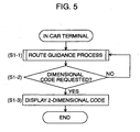
- Fig. 5 is a flow chart showing a process according to the present embodiment.
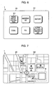
- Figs. 6 and 7 show examples of screens displayed on the display unit 23 of the navigation apparatus 1.
- Fig. 8 is a flow chart of a process according to the present embodiment.
- Fig. 9 is a schematic diagram showing examples of screens displayed on the display unit 31 of the portable terminal 2.
- the navigation apparatus 1 is now providing route guidance by displaying a route from a current position to a destination on the display unit 23.
- the navigation apparatus 1 operates as follows.
- the navigation apparatus 1 (the controller 5) is executing a route guidance program to provide route guidance from the current position to the destination by displaying a map of a current-position area on the display unit 23 (step S1-1).
- the user When a user parks a vehicle M at a parking lot or the like en route to the destination and leaves the vehicle M, the user operates a switch on the input unit 8 of the navigation apparatus 1 to display a setting screen G1 shown in Fig. 6 for transferring information associated with the destination on the display unit 23.
- the setting screen G1 includes an address setting button, a history button, and a destination transfer button S1. If a user touches the destination transfer button S1 on the setting screen G1, the navigation apparatus 1 (the controller 5) determines that a destination transfer command has been issued (step S1-2 is answered affirmatively), the navigation apparatus 1 produces a 2-dimensional code by the code generator 13 and displays the generated 2-dimensional code on the display unit 23 (step S1-3).
- the 2-dimensional code C is displayed, as shown in Fig. 7 , in a display area R in a lower right corner of the display unit 23 on which the map is also displayed.
- the 2-dimensional code C includes coded information associated with the current position and/or the destination set by the user in the navigation apparatus 1.
- the 2-dimensional code C can include a large amount of information in a small area and can be read from an arbitrary direction.
- the information associated with the current position is given by the position detection unit 6, and the information associated with the destination is read from the storage unit 7.
- the 2-dimensional code C displayed also includes coded information associated with the URL of the server 3 of the information center and authentication information needed to access the server 3. The information associated with the URL and the authentication information represented in the 2-dimensional code C are acquired from the storage unit 7.
- the user captures the image of the 2-dimensional code C using the digital camera 32 of the portable terminal 2 (step S1-4) .
- the controller 25 temporarily stores the captured 2-dimensional code as image data (image information) in the storage unit 26.
- the controller 25 transmits the image data of the 2-dimensional code stored in the storage unit 26 to the server 3 (step S1-5).
- the portable terminal 2 After the transmission of the image data of the 2-dimensional code, the portable terminal 2 (the controller 25) waits for route guidance information transmitted, in response to the image data, from the server 3 (step S1-6). More specifically, in accordance with information indicated by the image data (the 2-dimensional code), the server 3 transmits route guidance information or error information to the portable terminal 2. Depending on the situation, the route guidance information includes route information and train schedule information (timetable information) or includes only route information. In a case in which the server 3 receives image data (2-dimensional code) from an unauthorized portable terminal, the server 3 transmits, to the portable terminal, error information including a message indicating that the portable terminal is not allowed to receive route guidance.
- the portable terminal 2 displays the route guidance from the current position to the destination on the display unit 31.
- the route guidance information received from the server 3 includes schedule information of the public transportation system to be used en route to the destination, as well as the route information
- the schedule information is also displayed on the display unit 31 (step S1-7a). More specifically, if the portable terminal 2 (the controller 25) receives the route information and the train schedule information, the portable terminal 2 (the controller 25) first displays a menu screen K1 on the display unit 31 as shown in Fig. 9 . The place name of the current position and the place name of the destination are displayed on the menu screen K1.
- the menu screen K1 also includes items of "Search for route”, "Display current-position area”, and "Display destination area”, which are selectable by pressing a corresponding button. As shown in Fig. 9 , if "Search for route” is selected, the portable terminal 2 (the controller 25) displays a route display screen K2. In a case in which "Display current-position area” is selected, a current-position area map screen K3 is displayed. If “Display destination area” is selected, a destination are map screen K4 is displayed.
- a route guidance map from the current position to the destination is displayed.
- a departure station and a departure time table, a transfer station and a transfer time table, and an arrival station and an arrival time table are also displayed.
- a map of an area in the vicinity of the current position is displayed.
- a map of an area in the vicinity of the destination is displayed. The user can easily reach the destination in accordance with information displayed on the screens K2 to K4.
- the user can easily determine by what time it is necessary to reach the departure station, based on the displayed information associated with the departure station and the departure times, the transfer station and the transfer time table, and the arrival station and the arrival time table.
- the portable terminal 2 displays the map indicating route guidance from the current position to the destination on the display unit 31 (step S1-7b). More specifically, the portable terminal 2 (the controller 25) displays the menu screen K1, the route display screen K2, the current-position area map screen K3, and the destination area map screen K4 similar to those shown in Fig. 9 except that train schedule information is hot displayed on the route display screen K2. Thus, the user can easily reach the destination in accordance with information displayed on the screens K2 to K4.
- step S1-6 the portable terminal 2 (the controller 25) displays, on the display unit 31, a message indicating that displaying of route guidance is not allowed (step S1-7c).
- the server 3 waits for the image data of the 2-dimensional code transmitted from the portable terminal 2, while performing normal processing (steps S1-8 and S1-9). If the image data is received (if step S1-9 is answered affirmatively), the data transmission/reception unit 37 of the server 3 analyzes the 2-dimensional code included in the received image data (step S1-10). More specifically, the data transmission/reception unit 37 extracts information associated with the current position, information associated with the destination, and authentication information needed to access the server 3, from the image data of the 2-dimensional code.
- step S1-11 If the data transmission/reception unit 37 can extract neither information associated with the current position and the destination (position information) nor the authentication information needed to access the server 3 (that is, if step S1-11 is answered negatively), the data transmission/reception unit 37 of the server 3 performs normal processing (step S1-8) and waits for arrival of image data of a 2-dimensional code transmitted from the portable terminal 2 (step S1-9).
- step S1-11 If information associated with the current position and the destination (position information) and authentication information are successfully extracted from the image data (that is, if step S1-11 is answered affirmatively), the data transmission/reception unit 37 compares the extracted authentication information with pre-registered authentication information (step S1-12). More specifically, the data transmission/reception unit 37 verifies the received authentication information based on user information stored in a user information storage unit (not shown). If the authentication is unsuccessful (step S1-12 is answered negatively), the data transmission/reception unit 37 transmits error information to the portable terminal 2 (step S1-13).
- the server 3 searches for a route from the current position (car-parking position) to the destination, based on the extracted information associated with the current position and the destination (step S1-14). More specifically, the route search unit 38 of the server 3 produces optimum route information indicating an optimum route from the current position (car-parking position) to the destination based on search data stored in the search data storage unit 41. The route search unit 38 extracts map data (map information) from the map data storage unit 40 based on the optimum route information, and produces route information used to display a map including the optimum route.
- map data map information
- the route search unit 38 then examines the produced optimum route information to determine whether a public transportation system is to be used en route. (step S1-15). If it is determined that no public transportation system is used en route to the destination (step S1-15 is answered negatively), the server 3 (the data transmission/reception unit 37) transmits the optimum route information as route information to the portable terminal 2 (step S1-16).
- the associated information search unit 39 of the server 3 acquires train schedule data (step S1-17). More specifically, the associated information search unit 39 reads information from the search data storage unit 41 of the server 3 and produces information associated with routes (lines) of the public transportation system such as a train system. The associated information search unit 39 reads train schedule information from a train schedule storage unit (not shown) of the server 3 and produces a train schedule table (indicating a departure station, a departure time, an arrival station, and an arrival time (and also a transfer station and a transfer time, if transfer is necessary)). The data transmission/reception unit 37 transmits train schedule information including the train line information and the train schedule table together with the route information to the portable terminal 2 (step S1-18).
- the first example described above provides the following advantages.
- the navigation apparatus 1 produces a 2-dimensional code based on information (position information) associated with a car-parking position and a destination, and displays the produced 2-dimensional code on the display unit 23.
- the portable terminal 2 reads the displayed 2-dimensional code by capturing the image of the 2-dimensional code using the digital camera 32 and transmits the image data to the server 3.
- the server 3 extracts the position information by analyzing the received image data.
- the server 3 searches for a route from the car-parking position to the destination based on the extracted position information, and transmits route guidance information indicating the detected route to the portable terminal 2.
- the user can acquire information associated with the route from the car-parking position to the destination via the portable terminal 2, even if the portable terminal 2 does not have a position detection capability using a GPS or the like, a route searching capability, and a 2-dimensional code analysis capability.
- the user does not need to operate input buttons or the like of the portable terminal 2 to input information associated with the destination. This provides great convenience to the user.
- a second example for explaining the present invention is described below with reference to Fig. 10 .
- the second example is similar to the first example except for some modification in processing.
- the controller 25 (analysis means) of the portable terminal 2 analyzes the image data of the 2-dimensional code
- the data transmission/reception unit 37 of the server 3 does not analyze the image data of the 2-dimensional code.
- step S1-4 if an image of a 2-dimensional code is captured using the digital camera 32 of the portable terminal 2, the controller 25 temporarily stores the captured 2-dimensional code as image data in the storage unit 26.
- the controller 25 analyzes the 2-dimensional code included in the captured image data (step S2-1). That is, the controller 25 extracts information (position information) associated with a current position and a destination and authentication information needed to access the server 3, from the image data of the 2-dimensional code.
- step S2-2 If the controller 25 can extract neither position information nor authentication information needed to access the server 3 (step S2-2 is answered negatively), the controller 25 displays an error message on the display unit 31 (step S2-3). On the other hand, if position information and authentication information are successfully extracted from the image data (step S2-2 is answered affirmatively), the controller 25 transmits the extracted position information and authentication information to the server 3 (step S2-4). Thereafter, as in the first embodiment, the portable terminal 2 (the controller 25) waits for route guidance information transmitted, in response to the image data (the 2-dimensional code), from the server 3 (step S1-6).
- the server 3 waits for the position information and the authentication information transmitted from the portable terminal 2 (step S2-5). If position information and authentification information are received (step S2-5 is answered affirmatively), the data transmission/reception unit 37 performs processing in a similar manner to the first example (steps S1-12 to S1-18) to produce route guidance information or error information and transmit the produced information to the portable terminal 2.
- the second example described above provides the following advantages.
- the navigation apparatus 1 produces a 2-dimensional code based on position information associated with a current position (a car-parking position) and a destination, and displays the produced 2-dimensional code on the display unit 23.
- the portable terminal 2 reads the displayed 2-dimensional code by capturing the image of the 2-dimensional code using the digital camera 32 and analyzes the image data (the 2-dimensional code).
- the portable terminal 2 extracts the position information from the 2-dimensional code and transmits the extracted position information to the server 3.
- the server 3 searches for a route from the car-parking position to the destination based on the position information received from the portable terminal 2 and transmits route guidance information to the portable terminal 2.
- the user can acquire information associated with the route from the car-parking position to the destination via the portable terminal 2, even if the portable terminal 2 does not have a position detection capability using a GPS or the like and a route searching capability.
- the user does not need to operate input buttons or the like of the portable terminal 2 to input information associated with the destination. This provides great convenience to the user.
- the server 3 does not need to analyze the image data (the 2-dimensional code), and thus a processing burden imposed on the server 3 is reduced.
- a first embodiment of the present invention is described below with reference to Figs. 11 and 12 .
- the embodiment is similar to the second example except for some modifications in the configuration of the portable terminal 2 and the process performed by the portable terminal 2.
- similar parts to those in the second example are denoted by similar reference numerals, and the explanation is focused on the difference from the first example.
- the present embodiment is different from the second example in that route guidance information is produced not by the server 3 but by the portable terminal 2.
- the portable terminal 2 stores map data, search data and facility data in the storage unit of the portable terminal 2, and the controller 25 has a capability of searching for a route from a current position to a destination and a capability of searching for facilities located in various areas.
- the controller 25 of the portable terminal 2 has a capability of analyzing a 2-dimensional code by communicating with the navigation apparatus 1.
- Fig. 11 is a flow chart showing a process according to the present embodiment.
- Fig. 12 is a schematic diagram showing examples of screens displayed on the display unit 31 of the portable terminal 2.
- step S1-4 if an image of a 2-dimensional code is captured using the digital camera 32 of the portable terminal 2, the controller 25 temporarily stores the captured 2-dimensional code as image data in the storage unit 26.
- the controller 25 analyzes the 2-dimensional code included in the captured image data (step S2-1). That is, the controller 25 extracts information (position information) associated with a current position and a destination from the image data of the 2-dimensional code. Note that in the present embodiment the 2-dimensional code does not include authentication information for access to the server 3, because no data from the server 3 is necessary.
- step S2-2 If position information is extracted from the image data (step S2-2 is answered affirmatively), the controller 25 displays a menu screen K5 on the display unit 31 as shown in Fig. 12 , and waits for some item to be selected from the menu (steps S3-1 and 3-2).
- the "current position” and the "destination” extracted from the 2-dimensional code are displayed on the menu screen K5.
- the menu screen K5 also includes a "Search for route” button, a "Display current-position area” button, and a "Display destination area” button.
- step S3-2 If the "Search for route" button is selected on the menu screen K5 (step S3-2 is answered affirmatively), The controller 25 searches for a route from the current position to the destination based on the search data stored in the storage unit 26 (step S3-3). Based on optimum route information obtained as a result of the searching, the controller 25 produces route information used to display a map including the optimum route from map data stored in the storage unit 26, and the controller 25 displays the route on the display unit 31 of the portable terminal 2 (step S3-4). More specifically, a map screen K6 such as that shown in Fig. 12 is displayed on the display unit 31, and a map of a relative wide area indicating the route from the car-parking position to the destination is displayed on the map screen K6.
- a map screen K6 such as that shown in Fig. 12 is displayed on the display unit 31, and a map of a relative wide area indicating the route from the car-parking position to the destination is displayed on the map screen K6.
- step S3-2 If the "Display current-position area” button or the "Display destination area” button is selected on the menu screen K5 (step S3-2 is answered affirmatively), the controller 25 searches for map data associated with the current position or the destination based on the extracted position information (step S3-5).
- the controller 25 displays a map on the display unit 31 (step S3-6). That is, a display screen K8 is displayed on the display unit 31 and a map of an area in the vicinity of the current position (the car-parking position) or an area in the vicinity of the destination is displayed on the display screen K8 as shown in Fig. 12 .
- step S3-2 "Facilities in current-position area” or “Facilities in destination area” is selected on the menu screen K5 (step S3-2 is answered affirmatively), the controller 25 first displays a facility category selection screen K7, as shown in Fig. 12 . The controller 25 then searches for facilities associated with the current position or the destination based on a facility category selected on the facility category selection screen K7 and the extracted position information (step S3-7). The controller 25 displays information indicating detected facilities on the display unit 31 (step S3-8).
- the user moves in accordance with the map and the facility information displayed on the display unit 31 of the portable terminal 2.
- the first embodiment described above provides the following advantages.
- the navigation apparatus 1 produces a 2-dimensional code based on position information and displays the produced 2-dimensional code on the display unit 31.
- the portable terminal 2 reads the displayed 2-dimensional code by capturing the image of the 2-dimensional code using the digital camera 32 and analyzes the image data. Based on data obtained as a result of the analysis, the portable terminal 2 searches for a route from the current position (car-parking position) to the destination, a map of an area in the vicinity of the car-parking position or in the vicinity of the destination, and facilities. Based on information obtained via the searching, a screen indicating the map and facility information is displayed on the display unit 31 of the portable terminal 2.
- the user can acquire information associated with the route from the car-parking position to the destination via the portable terminal 2, even if the portable terminal 2 does not have a position detection capability using a GPS or the like.
- the user does not need to operate input buttons or the like of the portable terminal 2 to input information associated with the destination. This provides great convenience to the user.
- the portable terminal 2 has the route search capability, the user can acquire information associated with the route from the current position (car-parking position) to the destination by using the portable terminal 2 even in a bad communication environment.
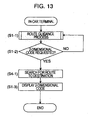
- a second embodiment of the present invention is described below with reference to Figs. 13 and 14 .
- the second embodiment is similar to the first embodiment except for some modifications in terms of the configuration of the navigation apparatus 1 and the processing performed by the navigation apparatus 1.
- the main controller 10 of the navigation apparatus 1 searches for a route from a current position (a car-parking position) to a destination, based on search data and map data stored in the storage unit 7 (step S4-1).
- the main controller 10 produces a 2-dimensional code based on optimum route information obtained as a result of the searching and based on information associated with the car-parking position and the destination.
- the main controller 10 displays the produced 2-dimensional code on the display unit 23 (step S1-3).
- the 2-dimensional code produced by the code generator 13 of the navigation apparatus 1 includes information associated with the current position, the destination, and the optimum route.
- the portable terminal 2 stores at least facility data in the storage unit 26.
- the portable terminal 2 captures a 2-dimensional code displayed on the display unit 23 of the navigation apparatus 1 by using the digital camera 32 (step S1-4).
- the controller 25 of the portable terminal 2 analyzes image data obtained by capturing the 2-dimensional code (step S2-1).
- step S2-2 If information (position information) associated with a current position and a destination and optimum route information are extracted from the image data (step S2-2 is answered affirmatively), the controller 25 performs processing similar to that performed in the third embodiment to display a map indicating a route, a map of an area in the vicinity of the current position or in the vicinity of the destination, and a screen indicating facility information on the display unit 31.
- the portable terminal 2 does not search for a route to the destination, because the optimum route information is provided from the navigation apparatus 1.
- the navigation apparatus 1 searches for a route from a current position (car-parking position) to a destination. Furthermore, the navigation apparatus 1 produces a 2-dimensional code based on the produced optimum route information, and displays the produced 2-dimensional code on the display unit 23.
- the portable terminal 2 reads the displayed 2-dimensional code by capturing the image of the 2-dimensional code using the digital camera 32 and analyzes the image data. A map indicating the route, a map of an area in the vicinity of the current position or in the vicinity of the destination, and a screen indicating facility information are displayed on the display unit 31 of the portable terminal 2.
- the user can acquire information associated with the route from the car-parking position to the destination via the portable terminal 2, even if the portable terminal 2 does not have a position detection capability using a GPS or the like and a searching capability.
- the user does not need to operate input buttons or the like of the portable terminal 2 to input information associated with the destination. This provides great convenience to the user.
- FIG. 15 A third example for explaining the present invention is described below with reference to Fig. 15 .
- the navigation apparatus 1 of the first example is modified as modified in the first embodiment.
- similar parts to those in the first embodiment are denoted by similar reference numerals, and the explanation is focused on the difference from the first example.
- the navigation apparatus 1 has the search capability based on search data and map data stored in the storage unit 7 of the navigation apparatus 1.
- the navigation apparatus 1 searches for an optimum route and produces a 2-dimensional code including optimum route information.
- the server 3 does not search for an optimum route, because the searching is performed by the navigation apparatus 1.
- the data transmission/reception unit 37 of the server 3 analyzes the image data of the 2-dimensional code to extract position information, optimum route information, and authentication information. If the authentication information is verified as valid (step S1-12 is answered affirmatively), the data transmission/reception unit 37 of the server 3 performs step S1-15 without performing a searching process.
- the third example described above provides advantages described below.
- the navigation apparatus 1 searches for a route from a car-parking position to a destination based on the position information. Furthermore, the navigation apparatus 1 produces a 2-dimensional code based on the produced optimum route information, and displays the produced 2-dimensional code on the display unit 23.
- the portable terminal 2 reads the displayed 2-dimensional code by capturing the image of the 2-dimensional code using the digital camera 32 and transmits the image data to the server 3.
- the server 3 analyzes the received image data to extract the optimum route information. Based on the extracted optimum route information, the server 3 produces route guidance information, a map of an area in the vicinity of the current position (car-parking position) or in the vicinity of the destination, and facility information and transmits the produced information to the portable terminal 2.
- the user can acquire information associated with the route from the car-parking position to the destination via the portable terminal 2, even if the portable terminal 2 does not have a position detection capability using a GPS or the like, a route searching capability, and a 2-dimensional code analysis capability.
- the user does not need to operate input buttons or the like of the portable terminal 2 to input information associated with the destination. This provides great convenience to the user.
- the server 3 does not need to perform the searching process, and thus a processing burden imposed on the server 3 is reduced.
- the navigation apparatus 1 when a user presses a destination transfer button S1 on the setting screen G1 displayed on the display unit 23 of the navigation apparatus 1, the navigation apparatus 1 displays the 2-dimensional code on the display unit 23.
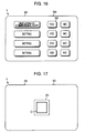
- the navigation apparatus 1 may display the 2-dimensional code on the display unit 23 when a car has reaches a vicinity of a destination. More specifically, if a selection button S2 corresponding to "Displaying of 2-dimensional code" on a setting screen G3 shown in Fig. 16 is pressed, the navigation apparatus 1 determines that a destination transfer command has been issued (step S1-2 is answered affirmatively). When the navigation apparatus 1 determines that the car has reached an area within a predetermined distance (for example, 500 m) from the destination or a departure station, the navigation apparatus 1 displays the 2-dimensional code including position information on the display unit 23.
- a predetermined distance for example, 500 m
- the code displayed on the display unit 23 of the navigation apparatus 1 is in the 2-dimensional form.
- a bar code may be used.
- the portable terminal captures the image of the bar code using the digital camera 32 thereby acquiring image data.
- the image data is analyzed by the portable terminal 2 or the server 3 to extract the information associated with the current position and the destination.
- the 2-dimensional code C may be displayed on a screen 50 on the display unit 23 of the navigation apparatus 1 as shown in Fig. 17 . More specifically, for example, the 2-dimensional code C may be displayed in a display area Z1 located at the substantial center of the screen 50.
- a screen 51 may be displayed on the display unit 23 of the navigation apparatus 1, as shown in Fig. 18 . More specifically, a map of, for example, a current-position area may be displayed in an area Z2 on the left-hand side of the screen 51, and a 2-dimensional code C may be displayed in an area Z3 on the right-hand side of the screen 51.
- the server 3 may not perform the process of searching for a route or a running schedule of a transportation system.
- information associated with routes of public transportation systems such as a train system may be stored in the storage unit 26 of the portable terminal 2.
- the controller 25 of the portable terminal 2 may produce information associated with a route and a running schedule of a transportation system based on the information stored in the storage unit 26.
- the 2-dimensional code produced by the navigation apparatus and read by the portable terminal 2 may be analyzed by the server 3 and resultant decoded data may be returned to the portable terminal 2.
- the authentication process performed between the portable terminal 2 and the server 3 may be omitted.
- the 2-dimensional code does not need to include authentication information, and thus it is possible to reduce the data size of the code.
- the portable terminal 2 may have the position detection capability using a GPS or the like, and may further have the route searching capability. Even in this case, the portable terminal 2 can acquire the information associated with the destination from the navigation apparatus 1 without needing to re-input the information. This is very convenient for the user.
- the navigation apparatus 1 is assumed to be installed in the vehicle M, Alternatively, the navigation apparatus 1 may be a terminal installed, for example, in a store, an office, or other locations.
- 2-dimensional codes examples include the QR code (DENSO), the PDF417 (Symbol Technologies), the DataMatrix code (RVSI Acuity CiMatrix), and the Maxi Code (UPS).
- QR code DEX
- PDF417 PDF417
- RVSI Acuity CiMatrix DataMatrix code
- UPS Maxi Code
Landscapes
- Engineering & Computer Science (AREA)
- Radar, Positioning & Navigation (AREA)
- Remote Sensing (AREA)
- Automation & Control Theory (AREA)
- Physics & Mathematics (AREA)
- General Physics & Mathematics (AREA)
- Navigation (AREA)
- Instructional Devices (AREA)
- Traffic Control Systems (AREA)
Claims (9)
- Procédé de navigation, comprenant :une étape, effectuée par un appareil de navigation (1),de détection d'une position actuelle d'un utilisateur ;une étape (S1-1), effectuée par l'appareil de navigation (1), de recherche d'un itinéraire de la position actuelle à une destination ;une étape (S1-3), effectuée par l'appareil de navigation (1), de production d'un code basé sur des informations associées à la destination et à la position actuelle en route vers la destination etl'affichage du code produit sur un affichage (9) ;une étape (S1-4, S1-7a, b, S3-4), effectuée par un terminal portable (2), d'acquisition des informations d'image du code par l'acquisition de l'image du code affiché sur l'affichage (9), etune étape, effectuée par le terminal portable (2), de fourniture d'un guidage d'itinéraire sur la base des informations d'image acquises.
- Procédé de navigation selon la revendication 1, comprenant en outre une étape (S1-8-S1-10), effectuée par un serveur d'informations (3) relié au terminal portable (2) par l'intermédiaire d'une ligne de communication bidirectionnelle, de réception d'informations d'image produites par l'acquisition de l'image du code par le terminal portable (2), et d'extraction d'informations associées à la position actuelle et à la destination par l'analyse des informations d'image reçues.
- Procédé de navigation selon la revendication 1, comprenant en outre une étape (S2-1, S2-4), effectuée par le terminal portable (2), d'extraction d'informations associées à la position actuelle et à la destination par l'analyse des informations d'image obtenues par l'acquisition de l'image du code.
- Procédé de navigation selon l'une des revendications 1 à 3, comprenant en outre une étape (S1-14), effectuée par un serveur d'informations (3), de recherche d'un itinéraire de la position actuelle à la destination sur la base des informations extraites associées à la position actuelle et à la destination, et de transmission des informations associées à l'itinéraire.
- Procédé de navigation selon l'une des revendications 1 à 3, comprenant en outre une étape (S3-3), effectuée par le terminal portable (2), de recherche d'un itinéraire de la position actuelle à la destination sur la base des informations extraites associées à la position actuelle et à la destination.
- Procédé de navigation selon l'une des revendications 2 et 3, comprenant en outre une étape (S4-1), effectuée par l'appareil de navigation (1), de recherche d'un itinéraire de la position actuelle à la destination sur la base des informations associées à la position actuelle et à la destination, et d'incorporation d'informations associées à l'itinéraire dans le code.
- Procédé de navigation selon l'une des revendications 1 à 6, comprenant en outre une étape (S1-15-S1-18), effectuée par un serveur d'informations (3) relié au terminal portable (2) par l'intermédiaire d'une ligne de communication bidirectionnelle, de production d'informations sur un itinéraire ou un horaire de fonctionnement d'un système de transport sur la base des informations extraites associées à la position actuelle et à la destination et de transmission des informations produites sur l'itinéraire ou l'horaire de fonctionnement du système de transport au terminal portable.
- Procédé de navigation selon l'une des revendications 1 à 7, comprenant en outre une étape (S3-2, S3-7, S3-8), effectuée par le terminal portable (2) ou un serveur d'informations (3) relié au terminal portable (2) par l'intermédiaire d'une ligne de communication bidirectionnelle, de transmission d'informations d'infrastructures associées à la position actuelle ou d'informations d'infrastructures associées à la destination au terminal portable, sur la base des informations extraites associées à la position actuelle et à la destination.
- Système de navigation comprenant :un appareil de navigation (1) comprenant un moyen de détection de position actuelle (6) pour détecter une position actuelle ;un moyen d'affichage (9) pour afficher des informations de carte ;un moyen de recherche d'itinéraire pour rechercher un itinéraire de la position actuelle à une destination ;un moyen de commande (5) pour générer un code sur la base d'informations associées à l'itinéraire jusqu'à la destination ;un moyen d'affichage (9) pour afficher le code généré ;dans lequel des informations d'image du code sont acquises par un moyen d'acquisition d'un terminal portable (2), dans lequel le terminal portable (2) est apte à fournir un guidage d'itinéraire sur la base des informations d'image acquises, etle terminal portable (2) comprenantun moyen d'entrée (27) pour acquérir une image d'un code affiché sur le moyen d'affichage (9) de l'appareil de navigation (1), dans lequel le code comprend des informations associées à la destination et à la position actuelle en route vers la destination ;un moyen d'acquisition d'informations d'image du code en utilisant l'image acquise ;un organe de commande (25) pour analyser l'image acquise et extraire les informations associées à la destination et à la position actuelle en route vers la destination, dans lequel l'organe de commande (25) est en outre apte à produire des informations d'itinéraire comprenant un itinéraire optimal et à afficher l'itinéraire optimal sur l'unité d'affichage (31) du terminal portable.
Applications Claiming Priority (2)
| Application Number | Priority Date | Filing Date | Title |
|---|---|---|---|
| JP2004127107 | 2004-04-22 | ||
| JP2004127107A JP4613511B2 (ja) | 2004-04-22 | 2004-04-22 | 経路案内方法、及びナビゲーション装置 |
Publications (2)
| Publication Number | Publication Date |
|---|---|
| EP1589321A1 EP1589321A1 (fr) | 2005-10-26 |
| EP1589321B1 true EP1589321B1 (fr) | 2015-08-26 |
Family
ID=34934602
Family Applications (1)
| Application Number | Title | Priority Date | Filing Date |
|---|---|---|---|
| EP05006966.5A Ceased EP1589321B1 (fr) | 2004-04-22 | 2005-03-30 | Procédé de guidage routier, appareil de navigation, terminal portable et serveur d'informations |
Country Status (3)
| Country | Link |
|---|---|
| US (1) | US7389182B2 (fr) |
| EP (1) | EP1589321B1 (fr) |
| JP (1) | JP4613511B2 (fr) |
Families Citing this family (31)
| Publication number | Priority date | Publication date | Assignee | Title |
|---|---|---|---|---|
| EP1777497A4 (fr) * | 2004-08-11 | 2011-03-02 | Pioneer Corp | Dispositif de guidage du deplacement, dispositif portatif de guidage du deplacement, systeme de guidage du deplacement, methode de guidage du deplacement, programme de guidage du deplacement et support d'enregistrement sur lequelle programme est enregistre |
| JP2006308554A (ja) * | 2005-03-31 | 2006-11-09 | Denso Corp | 施設検索装置、及びナビゲーション装置 |
| JP4262241B2 (ja) * | 2005-11-30 | 2009-05-13 | 株式会社ナビタイムジャパン | オフライン経路表示システム、携帯端末装置および認識コード生成装置 |
| US20070126603A1 (en) * | 2005-12-06 | 2007-06-07 | Driscoll Shon T | Method and system for locating parked cars |
| US7571050B2 (en) * | 2006-03-27 | 2009-08-04 | Microsoft Corporation | Transit-coordinated local search |
| DE602006010866D1 (de) * | 2006-07-27 | 2010-01-14 | Aisin Aw Co | Navigationsgerät und -Verfahren |
| JP5039340B2 (ja) * | 2006-08-31 | 2012-10-03 | 富士通株式会社 | データ入力装置、データ入力システム、データ入力方法、印刷装置および印刷物 |
| JP5278786B2 (ja) * | 2007-03-29 | 2013-09-04 | 株式会社沖データ | 地図情報出力システム |
| JP2009044328A (ja) | 2007-08-07 | 2009-02-26 | Seiko Epson Corp | 会議システム、サーバ、画像表示方法、コンピュータプログラム及び記録媒体 |
| US11441919B2 (en) * | 2007-09-26 | 2022-09-13 | Apple Inc. | Intelligent restriction of device operations |
| US8498808B2 (en) * | 2008-01-18 | 2013-07-30 | Mitac International Corp. | Method and apparatus for hybrid routing using breadcrumb paths |
| US8700314B2 (en) | 2008-01-18 | 2014-04-15 | Mitac International Corporation | Method and apparatus to search for local parking |
| US8290703B2 (en) * | 2008-01-18 | 2012-10-16 | Mitac International Corporation | Method and apparatus for access point recording using a position device |
| JP5018540B2 (ja) * | 2008-02-18 | 2012-09-05 | トヨタ自動車株式会社 | 交通機関情報取得システム |
| US8576092B2 (en) * | 2008-04-08 | 2013-11-05 | Anagog Ltd. | System and method for identifying parking spaces for a community of users |
| TWI384201B (zh) * | 2008-08-21 | 2013-02-01 | Mstar Semiconductor Inc | 識別標籤導航系統與應用於其上之方法 |
| US20100082490A1 (en) * | 2008-09-30 | 2010-04-01 | Apple Inc. | Systems and methods for secure wireless transactions |
| US20100161209A1 (en) * | 2008-12-19 | 2010-06-24 | Honda Motor Co., Ltd. | Routing a User to a Parked Vehicle |
| US20110078236A1 (en) * | 2009-09-29 | 2011-03-31 | Olsen Jr Dan R | Local access control for display devices |
| WO2012131836A1 (fr) * | 2011-03-25 | 2012-10-04 | パイオニア株式会社 | Dispositif de guidage, unité de détection, dispositif terminal mobile, méthode de guidage, et programme de guidage |
| WO2012167148A2 (fr) * | 2011-06-03 | 2012-12-06 | Apple Inc. | Dispositifs et procédés pour comparer et sélectionner des itinéraires de navigation alternatifs |
| JP5942615B2 (ja) * | 2011-08-11 | 2016-06-29 | 株式会社Jvcケンウッド | 進路案内装置、進路案内方法およびプログラム |
| JP6004619B2 (ja) * | 2011-08-22 | 2016-10-12 | 富士通テン株式会社 | 車両用装置、情報送信方法、情報表示方法、及びプログラム |
| US20140035723A1 (en) * | 2012-08-06 | 2014-02-06 | General Electric Company | Mobile application system and method |
| DE102013003044B4 (de) * | 2013-02-22 | 2025-03-27 | Volkswagen Aktiengesellschaft | Übertragen von Informationen über ein Anzeigesystem eines Fahrzeugs |
| DE102015219692A1 (de) * | 2015-10-12 | 2017-04-13 | Siemens Aktiengesellschaft | Verfahren zum Bereitstellen von Reiseinformationen und Informationssystem |
| KR101745178B1 (ko) * | 2015-11-12 | 2017-06-08 | 현대자동차주식회사 | 내비게이션 장치 및 그 경로 정보 제공 방법 |
| JP7238656B2 (ja) * | 2019-07-11 | 2023-03-14 | トヨタ自動車株式会社 | 情報処理装置、及び、情報処理方法 |
| CN112164240A (zh) * | 2020-09-02 | 2021-01-01 | 广东飞企互联科技股份有限公司 | 一种停车场寻车方法和寻车系统 |
| JP2023038636A (ja) * | 2021-09-07 | 2023-03-17 | エヌ・ティ・ティ・コミュニケーションズ株式会社 | 情報提供装置、情報提供方法及び情報提供プログラム |
| CN115145277A (zh) * | 2022-07-01 | 2022-10-04 | 广东工贸职业技术学院 | 基于动态二维码的汽车自动驾驶定位导航方法及装置 |
Citations (1)
| Publication number | Priority date | Publication date | Assignee | Title |
|---|---|---|---|---|
| JP2004117285A (ja) * | 2002-09-27 | 2004-04-15 | Equos Research Co Ltd | 経路探索システム及び位置情報変換システム |
Family Cites Families (13)
| Publication number | Priority date | Publication date | Assignee | Title |
|---|---|---|---|---|
| US5187810A (en) * | 1988-06-10 | 1993-02-16 | Oki Electric Industry Co., Ltd. | Route guidance system for provding a mobile station with optimum route data in response to a guidance request together with base station data indicative of an identification of a base station |
| JP2002018155A (ja) * | 2000-07-03 | 2002-01-22 | Asahi Kaisetsu Jigyo Kk | 字幕表示装置 |
| JP3846189B2 (ja) * | 2000-12-14 | 2006-11-15 | 松下電器産業株式会社 | ナビゲーション装置 |
| JP2002323336A (ja) * | 2001-04-26 | 2002-11-08 | Equos Research Co Ltd | 経路情報提供方法,その装置,そのシステム |
| JP2003156340A (ja) | 2001-09-10 | 2003-05-30 | Pioneer Electronic Corp | ナビゲーションシステム、ナビゲーションシステム用情報サーバ装置および通信端末装置、並びに、ナビゲーションシステムにおける移動体の変更方法および変更処理プログラム |
| JP2003106845A (ja) * | 2001-09-28 | 2003-04-09 | Pioneer Electronic Corp | ナビゲーションシステム、移動体ナビゲーション装置及び通信ナビゲーション装置並びに情報サーバ装置、ナビゲーション方法、移動体ナビゲーション方法及び通信ナビゲーション方法並びにサーバ処理方法、ナビゲーション用プログラム、移動体ナビゲーション用プログラム及び通信ナビゲーション用プログラム並びにサーバ処理用プログラム及び情報記録媒体 |
| JP3733900B2 (ja) * | 2001-12-11 | 2006-01-11 | 日産自動車株式会社 | ナビゲーションシステム、データサーバ及び情報提供方法 |
| EP1502080B1 (fr) | 2002-04-30 | 2013-05-22 | Telmap Ltd. | Systeme de navigation utilisant des cartes de couloirs |
| JP2003346291A (ja) * | 2002-05-27 | 2003-12-05 | Mars:Kk | タクシー走行ルート指示システム及びタクシー走行ルート指示方法 |
| JP3937939B2 (ja) | 2002-06-14 | 2007-06-27 | アイシン・エィ・ダブリュ株式会社 | ナビゲーションシステム及び経路案内データ記録方法のプログラム |
| EP1517272A4 (fr) * | 2002-06-24 | 2007-05-09 | Sumitomo Heavy Industries | Systeme et procede de gestion pour portail de passage de vehicule |
| WO2004059251A1 (fr) | 2002-12-27 | 2004-07-15 | Nokia Corporation | Procede de gestion de donnees de localisation |
| JP2005274472A (ja) * | 2004-03-26 | 2005-10-06 | Equos Research Co Ltd | 案内装置及び携帯端末 |
-
2004
- 2004-04-22 JP JP2004127107A patent/JP4613511B2/ja not_active Expired - Lifetime
-
2005
- 2005-03-29 US US11/091,343 patent/US7389182B2/en not_active Expired - Lifetime
- 2005-03-30 EP EP05006966.5A patent/EP1589321B1/fr not_active Ceased
Patent Citations (1)
| Publication number | Priority date | Publication date | Assignee | Title |
|---|---|---|---|---|
| JP2004117285A (ja) * | 2002-09-27 | 2004-04-15 | Equos Research Co Ltd | 経路探索システム及び位置情報変換システム |
Also Published As
| Publication number | Publication date |
|---|---|
| EP1589321A1 (fr) | 2005-10-26 |
| JP2005308588A (ja) | 2005-11-04 |
| US7389182B2 (en) | 2008-06-17 |
| JP4613511B2 (ja) | 2011-01-19 |
| US20050240344A1 (en) | 2005-10-27 |
Similar Documents
| Publication | Publication Date | Title |
|---|---|---|
| EP1589321A1 (fr) | Procédé de guidage routier, appareil de navigation, terminal portable et serveur d'informations | |
| US8970733B2 (en) | Visual pairing and data exchange between devices using barcodes for data exchange with mobile navigation systems | |
| JP2004213191A (ja) | 地図情報提供システムおよびその携帯端末 | |
| US20100114861A1 (en) | System and method for information acquisition | |
| JP5278786B2 (ja) | 地図情報出力システム | |
| JP2006125871A (ja) | ナビゲーション装置 | |
| JP2004252661A (ja) | 駐車場システム | |
| JP2019184336A (ja) | カーナビゲーション装置の目的地設定システム | |
| JP2003177025A (ja) | ナビゲーションシステム、データサーバ及び情報提供方法 | |
| JP2005274472A (ja) | 案内装置及び携帯端末 | |
| JP2006112981A (ja) | 情報処理装置 | |
| JP3797196B2 (ja) | ナビゲーションシステム、データサーバ、経路設定方法及びデータサーバの情報提供方法 | |
| KR101136145B1 (ko) | 위치 기반 서비스를 이용한 휴대용 단말기의 체크인 시스템 및 이를 이용한 체크인 방법 | |
| KR20100060926A (ko) | 상황 인지 서비스를 제공하는 시스템 및 그 방법 | |
| JP2002181580A (ja) | ナビゲーションシステム及びナビゲーション装置 | |
| JP2003156360A (ja) | 携帯情報処理装置およびナビゲーションシステム | |
| JP2006235691A (ja) | 会場案内システム | |
| JP2004112050A (ja) | 通信端末装置、その接続制御方法、そのプログラム | |
| JP2007258906A (ja) | ナビゲーション装置および携帯電話 | |
| JP2002357434A (ja) | カーナビゲーション装置及びカーナビゲーション装置を用いた駐車場管理システム | |
| JP2011237357A (ja) | ナビゲーション装置 | |
| EP0986013A2 (fr) | Système de recouvrement de données | |
| JP2018013840A (ja) | 情報コード及び情報取得システム | |
| KR101028098B1 (ko) | 상황 인지 서비스를 제공하는 시스템 및 그 방법 | |
| JPH114483A (ja) | ナビゲーション装置 |
Legal Events
| Date | Code | Title | Description |
|---|---|---|---|
| PUAI | Public reference made under article 153(3) epc to a published international application that has entered the european phase |
Free format text: ORIGINAL CODE: 0009012 |
|
| AK | Designated contracting states |
Kind code of ref document: A1 Designated state(s): AT BE BG CH CY CZ DE DK EE ES FI FR GB GR HU IE IS IT LI LT LU MC NL PL PT RO SE SI SK TR |
|
| AX | Request for extension of the european patent |
Extension state: AL BA HR LV MK YU |
|
| 17P | Request for examination filed |
Effective date: 20060419 |
|
| AKX | Designation fees paid |
Designated state(s): DE FR GB IT |
|
| 17Q | First examination report despatched |
Effective date: 20080508 |
|
| GRAJ | Information related to disapproval of communication of intention to grant by the applicant or resumption of examination proceedings by the epo deleted |
Free format text: ORIGINAL CODE: EPIDOSDIGR1 |
|
| GRAP | Despatch of communication of intention to grant a patent |
Free format text: ORIGINAL CODE: EPIDOSNIGR1 |
|
| INTG | Intention to grant announced |
Effective date: 20150511 |
|
| RIN1 | Information on inventor provided before grant (corrected) |
Inventor name: TOMITA, HIROSHI Inventor name: NAGASE, KENJI |
|
| GRAS | Grant fee paid |
Free format text: ORIGINAL CODE: EPIDOSNIGR3 |
|
| GRAA | (expected) grant |
Free format text: ORIGINAL CODE: 0009210 |
|
| AK | Designated contracting states |
Kind code of ref document: B1 Designated state(s): DE FR GB IT |
|
| REG | Reference to a national code |
Ref country code: GB Ref legal event code: FG4D |
|
| REG | Reference to a national code |
Ref country code: DE Ref legal event code: R096 Ref document number: 602005047320 Country of ref document: DE |
|
| REG | Reference to a national code |
Ref country code: FR Ref legal event code: PLFP Year of fee payment: 12 |
|
| PG25 | Lapsed in a contracting state [announced via postgrant information from national office to epo] |
Ref country code: IT Free format text: LAPSE BECAUSE OF FAILURE TO SUBMIT A TRANSLATION OF THE DESCRIPTION OR TO PAY THE FEE WITHIN THE PRESCRIBED TIME-LIMIT Effective date: 20150826 |
|
| REG | Reference to a national code |
Ref country code: DE Ref legal event code: R097 Ref document number: 602005047320 Country of ref document: DE |
|
| PLBE | No opposition filed within time limit |
Free format text: ORIGINAL CODE: 0009261 |
|
| STAA | Information on the status of an ep patent application or granted ep patent |
Free format text: STATUS: NO OPPOSITION FILED WITHIN TIME LIMIT |
|
| 26N | No opposition filed |
Effective date: 20160530 |
|
| REG | Reference to a national code |
Ref country code: FR Ref legal event code: PLFP Year of fee payment: 13 |
|
| REG | Reference to a national code |
Ref country code: FR Ref legal event code: PLFP Year of fee payment: 14 |
|
| PGFP | Annual fee paid to national office [announced via postgrant information from national office to epo] |
Ref country code: DE Payment date: 20200317 Year of fee payment: 16 Ref country code: GB Payment date: 20200318 Year of fee payment: 16 |
|
| PGFP | Annual fee paid to national office [announced via postgrant information from national office to epo] |
Ref country code: FR Payment date: 20200214 Year of fee payment: 16 |
|
| REG | Reference to a national code |
Ref country code: DE Ref legal event code: R119 Ref document number: 602005047320 Country of ref document: DE |
|
| GBPC | Gb: european patent ceased through non-payment of renewal fee |
Effective date: 20210330 |
|
| PG25 | Lapsed in a contracting state [announced via postgrant information from national office to epo] |
Ref country code: GB Free format text: LAPSE BECAUSE OF NON-PAYMENT OF DUE FEES Effective date: 20210330 Ref country code: FR Free format text: LAPSE BECAUSE OF NON-PAYMENT OF DUE FEES Effective date: 20210331 Ref country code: DE Free format text: LAPSE BECAUSE OF NON-PAYMENT OF DUE FEES Effective date: 20211001 |