EP1588971A1 - Method and apparatus for handling of printed products - Google Patents
Method and apparatus for handling of printed products Download PDFInfo
- Publication number
- EP1588971A1 EP1588971A1 EP05008056A EP05008056A EP1588971A1 EP 1588971 A1 EP1588971 A1 EP 1588971A1 EP 05008056 A EP05008056 A EP 05008056A EP 05008056 A EP05008056 A EP 05008056A EP 1588971 A1 EP1588971 A1 EP 1588971A1
- Authority
- EP
- European Patent Office
- Prior art keywords
- flexible sheet
- products
- gripper
- conveyor
- workstation
- Prior art date
- Legal status (The legal status is an assumption and is not a legal conclusion. Google has not performed a legal analysis and makes no representation as to the accuracy of the status listed.)
- Granted
Links
- 238000000034 method Methods 0.000 title claims abstract description 25
- 238000012545 processing Methods 0.000 claims abstract description 17
- 238000005520 cutting process Methods 0.000 claims description 9
- 238000003780 insertion Methods 0.000 claims description 4
- 230000037431 insertion Effects 0.000 claims description 4
- 239000000047 product Substances 0.000 description 80
- 230000032258 transport Effects 0.000 description 25
- 230000004087 circulation Effects 0.000 description 11
- 238000004026 adhesive bonding Methods 0.000 description 6
- 238000003462 Bender reaction Methods 0.000 description 5
- 238000002604 ultrasonography Methods 0.000 description 4
- WYWHKKSPHMUBEB-UHFFFAOYSA-N 6-Mercaptoguanine Natural products N1C(N)=NC(=S)C2=C1N=CN2 WYWHKKSPHMUBEB-UHFFFAOYSA-N 0.000 description 2
- 239000000853 adhesive Substances 0.000 description 2
- 230000001070 adhesive effect Effects 0.000 description 2
- 230000008859 change Effects 0.000 description 2
- 238000005516 engineering process Methods 0.000 description 2
- 230000005484 gravity Effects 0.000 description 2
- 238000012423 maintenance Methods 0.000 description 2
- 230000008569 process Effects 0.000 description 2
- 229940095374 tabloid Drugs 0.000 description 2
- 230000009471 action Effects 0.000 description 1
- 230000006978 adaptation Effects 0.000 description 1
- 238000005452 bending Methods 0.000 description 1
- 239000000969 carrier Substances 0.000 description 1
- 230000001419 dependent effect Effects 0.000 description 1
- 238000013461 design Methods 0.000 description 1
- 230000000694 effects Effects 0.000 description 1
- 230000003993 interaction Effects 0.000 description 1
- 238000003754 machining Methods 0.000 description 1
- 238000004519 manufacturing process Methods 0.000 description 1
- 238000005007 materials handling Methods 0.000 description 1
- 239000002243 precursor Substances 0.000 description 1
- 235000012046 side dish Nutrition 0.000 description 1
- 239000013589 supplement Substances 0.000 description 1
- 230000001360 synchronised effect Effects 0.000 description 1
- 238000009966 trimming Methods 0.000 description 1
- 230000003442 weekly effect Effects 0.000 description 1
Images


Classifications
-
- B—PERFORMING OPERATIONS; TRANSPORTING
- B65—CONVEYING; PACKING; STORING; HANDLING THIN OR FILAMENTARY MATERIAL
- B65H—HANDLING THIN OR FILAMENTARY MATERIAL, e.g. SHEETS, WEBS, CABLES
- B65H5/00—Feeding articles separated from piles; Feeding articles to machines
- B65H5/08—Feeding articles separated from piles; Feeding articles to machines by grippers, e.g. suction grippers
- B65H5/085—Feeding articles separated from piles; Feeding articles to machines by grippers, e.g. suction grippers by combinations of endless conveyors and grippers
-
- B—PERFORMING OPERATIONS; TRANSPORTING
- B65—CONVEYING; PACKING; STORING; HANDLING THIN OR FILAMENTARY MATERIAL
- B65H—HANDLING THIN OR FILAMENTARY MATERIAL, e.g. SHEETS, WEBS, CABLES
- B65H29/00—Delivering or advancing articles from machines; Advancing articles to or into piles
- B65H29/003—Delivering or advancing articles from machines; Advancing articles to or into piles by grippers
-
- B—PERFORMING OPERATIONS; TRANSPORTING
- B65—CONVEYING; PACKING; STORING; HANDLING THIN OR FILAMENTARY MATERIAL
- B65H—HANDLING THIN OR FILAMENTARY MATERIAL, e.g. SHEETS, WEBS, CABLES
- B65H29/00—Delivering or advancing articles from machines; Advancing articles to or into piles
- B65H29/02—Delivering or advancing articles from machines; Advancing articles to or into piles by mechanical grippers engaging the leading edge only of the articles
- B65H29/04—Delivering or advancing articles from machines; Advancing articles to or into piles by mechanical grippers engaging the leading edge only of the articles the grippers being carried by endless chains or bands
- B65H29/042—Intermediate conveyors, e.g. transferring devices
- B65H29/044—Intermediate conveyors, e.g. transferring devices conveying through a machine
-
- B—PERFORMING OPERATIONS; TRANSPORTING
- B65—CONVEYING; PACKING; STORING; HANDLING THIN OR FILAMENTARY MATERIAL
- B65H—HANDLING THIN OR FILAMENTARY MATERIAL, e.g. SHEETS, WEBS, CABLES
- B65H37/00—Article or web delivery apparatus incorporating devices for performing specified auxiliary operations
- B65H37/04—Article or web delivery apparatus incorporating devices for performing specified auxiliary operations for securing together articles or webs, e.g. by adhesive, stitching or stapling
-
- B—PERFORMING OPERATIONS; TRANSPORTING
- B65—CONVEYING; PACKING; STORING; HANDLING THIN OR FILAMENTARY MATERIAL
- B65H—HANDLING THIN OR FILAMENTARY MATERIAL, e.g. SHEETS, WEBS, CABLES
- B65H5/00—Feeding articles separated from piles; Feeding articles to machines
- B65H5/30—Opening devices for folded sheets or signatures
- B65H5/308—Opening devices for folded sheets or signatures the folded sheets or signatures travelling in hanging position
-
- B—PERFORMING OPERATIONS; TRANSPORTING
- B65—CONVEYING; PACKING; STORING; HANDLING THIN OR FILAMENTARY MATERIAL
- B65H—HANDLING THIN OR FILAMENTARY MATERIAL, e.g. SHEETS, WEBS, CABLES
- B65H2301/00—Handling processes for sheets or webs
- B65H2301/10—Selective handling processes
-
- B—PERFORMING OPERATIONS; TRANSPORTING
- B65—CONVEYING; PACKING; STORING; HANDLING THIN OR FILAMENTARY MATERIAL
- B65H—HANDLING THIN OR FILAMENTARY MATERIAL, e.g. SHEETS, WEBS, CABLES
- B65H2301/00—Handling processes for sheets or webs
- B65H2301/30—Orientation, displacement, position of the handled material
- B65H2301/32—Orientation of handled material
- B65H2301/323—Hanging
-
- B—PERFORMING OPERATIONS; TRANSPORTING
- B65—CONVEYING; PACKING; STORING; HANDLING THIN OR FILAMENTARY MATERIAL
- B65H—HANDLING THIN OR FILAMENTARY MATERIAL, e.g. SHEETS, WEBS, CABLES
- B65H2301/00—Handling processes for sheets or webs
- B65H2301/40—Type of handling process
- B65H2301/44—Moving, forwarding, guiding material
- B65H2301/447—Moving, forwarding, guiding material transferring material between transport devices
- B65H2301/4471—Grippers, e.g. moved in paths enclosing an area
- B65H2301/44712—Grippers, e.g. moved in paths enclosing an area carried by chains or bands
-
- B—PERFORMING OPERATIONS; TRANSPORTING
- B65—CONVEYING; PACKING; STORING; HANDLING THIN OR FILAMENTARY MATERIAL
- B65H—HANDLING THIN OR FILAMENTARY MATERIAL, e.g. SHEETS, WEBS, CABLES
- B65H2301/00—Handling processes for sheets or webs
- B65H2301/40—Type of handling process
- B65H2301/44—Moving, forwarding, guiding material
- B65H2301/447—Moving, forwarding, guiding material transferring material between transport devices
- B65H2301/4474—Pair of cooperating moving elements as rollers, belts forming nip into which material is transported
-
- B—PERFORMING OPERATIONS; TRANSPORTING
- B65—CONVEYING; PACKING; STORING; HANDLING THIN OR FILAMENTARY MATERIAL
- B65H—HANDLING THIN OR FILAMENTARY MATERIAL, e.g. SHEETS, WEBS, CABLES
- B65H2301/00—Handling processes for sheets or webs
- B65H2301/40—Type of handling process
- B65H2301/44—Moving, forwarding, guiding material
- B65H2301/447—Moving, forwarding, guiding material transferring material between transport devices
- B65H2301/44795—Saddle conveyor with saddle member extending transversally to transport direction
Definitions
- the invention is in the field of materials handling and relates to a method and a Device for transporting and possibly processing flexible flat products, in particular of printed products, according to the features of the preamble of claim 1 and the features of the preamble of claim 9.
- EP 0762950 examples of such inflexible working ways are disclosed in EP 0762950 and GB 5861.
- the print product to be trimmed is gripped by the gripper of a gripper transporter Cutting station supplied, delivered to this and after trimming by the gripper of the same transporter or a second downstream Greiftransporteurs of the Cutting station transported away.
- EP 0762950 describes the printed products for the cutting process passed to clamps to stabilize them for the cutting process and in a hold fixed position. The grippers of the gripper transporter remain during the cutting process associated with the printed products in the gripping clamps, so that the printed products of each supplied to the same grippers of the cutting station and also led away from it again.
- the cutting stations are a fixed part of the transport device.
- the Today's requirements for a rapid change of production e.g. from big ones Daily newspapers on weekly magazines, web brochures and various newspapers, Magazines, etc., such devices can not or only partially meet.
- the object of the present invention is therefore to provide a device and a method for To provide, with the transport and any processing of flat flexible Products in a cost effective and flexible way.
- the to be transported flexible sheet products in particular of printed products, from the same Greiftransportor to a workstation and from this workstation again away promoted, with the aid of a control device in each case a logical association between flexible flat products and grippers of Greiftransporturs takes place.
- the workstation is as required in the transport path insertable or removable. In this way The investment and maintenance costs can be reduced to a single gripper transporter and make the work process more flexible.
- the flexible sheet products can be used by the Gripper of the transporter to be grasped at the flower or at the fold.
- This control is particularly easy to implement in the event that the logical assignment in it There is the same gripper that conveys a flexible sheet product toward the workstation has also promoted this flexible sheet product away from the workstation.
- the control device is also able to control the method so that by logical assignment of grippers and flexible flat products to each other, a gripper, the one flexible flat product has promoted to a workstation, another flexible planar Promote product away from the workstation. In this way can speed differences be mastered.
- the flexible sheet products for the Machining supported by a support element.
- the flexible sheet products are grasped by the transporter's grippers at the flower or at the fold become the products either deposited with the fold from above on the support elements or the support elements are introduced between the products and support the flexible laminar products at theirs against down-aligned fold.
- the transport can lead across several workstations that are related to the transport path of the Greiftransporteurs downstream one behind the other and / or in parallel, over points interconnected strands of Greiftransportor can be arranged.
- connection devices in particular staplers, Ultrasonic devices, devices for adhesive bonding and / or devices for Inserting flexible sheet products, and / or the end of a collection or Sammelheftumble and / or the end of a plug-in and / or Einsteckhefttier provided be.
- FIGS. 1 to 8 relate to the transport of typically folded in Tabloidform sheet single or several on top of each other can be transported by means of a gripping transporter 12 and regardless of their number of single sheets / plies are referred to as printed product 16 for the sake of simplicity. It understands that other flexible sheet products 16 transported and processed in this way can be.
- the examples 1 to 8 shown is also for the sake of simplicity as Workstation 2, each showing a stapler 38 As will be explained below, It is possible depending on the desired work result, other apparatus or devices than Provide workstations 2.
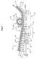
- FIG. 1 shows a device 10 according to the invention with a gripping transporter 12 which is mounted on a gripper conveyor 12 endlessly circulating conveying member 15 gripper 14 transported
- the grippers 14 are provided with gripping jaws 13 equipped with those in the usual way of several folded sheets existing Printed products 16 can be taken.
- the Printed products 16 at their respective fold 18 and gripped by the grippers 14 in the conveying direction F transported.
- the fold 18 opposite flower 20 of each printed product 16 is the Following gravity downwards
- the device 10 according to the invention has an opening device in this example 22 with a circumferential Auslenkband 24 an adjoining opening wheel 26th and a helix 30 adjoining the opening wheel 26.
- More elements of here shown device 10 according to the invention are a connecting device 36, which in this Example as Rotationsheftapparat 38 is configured as well as a circulation, which at its endless Circumferential conveyor member 15 'at a defined distance from each other support elements 34 has.
- at the stapler 38 is a conventional rotary stapler on a support disc 39 has a plurality of evenly spaced stitching heads 40 such a stapler is e.g. in WO 02/36474 in FIG. 8 or also in EP0606555 and in EP0691215.
- the Support members 34 of the circulation 32 have Umbieger 42, which is used to carry out a Heftvorganges cooperate with the stitching heads 40 of the stapler 38. But it can also Umbieger be provided, which separated from the support elements and arranged by these are independently movable.
- the conveyor 10 of the device 10 according to the invention will now be described directly from the rotation, from a buffer device or any other Conveyor printed products 16 taken and fed to a workstation 2.
- the Printed products can consist of one or more single sheets / layers, and possibly in Tabloidform folded and superimposed sheet exist (not shown here).
- the feed dog 12 transports the printed products 16 into the region of Opening device 22, wherein the flowers of the printed products 16 on the circulating Auslenkband 24 of the opening device 22 accumulate, through which they in the conveying direction F be deflected, as can be seen from Fig.
- the printed products 16 are opened on the flower side and during further transport in Conveying direction F held open over the helix 30, in an allocation area 31 are the opened printed products 16 stored on the support members 34 of the circulation 32.
- the grippers 14 are not actively opened but remain closed and the support elements 34 penetrate against the clamping action of the gripper jaws 13 between the Gripping jaws 13 a.
- the distances between the grippers 14 on the conveyor 12 and the distances between the support elements 34 of Circulation 32 and their speed are matched accordingly, so that a easy assignment of the gripper 14 - and with them the printed products 16 - to the Supporting elements 34 can take place and the grippers 14 with the support elements 34 in the conveying direction F can run substantially synchronously.
- the stapler 38 takes place in the usual A stapling, wherein the integrated in the support members 34 Umbieger 42 for the Close the inserted through the stitching heads 40 in the printed products 16 wire clips to care. It is understood that the arrangement of the stitching heads on the support plate 39 of the Rotationsheftapparates 38 and the rotational speed of the support plate 39 tuned are on the distances of the gripper 14 and the support members 34 and the conveying speed in Direction F.
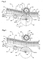
- FIGS. 2 and 3 show a further embodiment of the device 10 according to the invention which substantially corresponds to the embodiment of FIG. 1.
- the support members 34 are in the examples of Figs. 2 and 3, the support members 34 not in a circulation 32 arranged on an endless circulating conveyor member 15 ', but they are in a wheel-shaped arrangement 44 about a central axis of rotation B on a circular path K. moved
- the support members 34 may be formed in the form of known saddles or pads be or only by appropriately stable formed Umbieger (see Fig. 9 and 10).
- the the same also applies to the support elements 34 of the embodiment of FIG Inventive method as above in connection with the embodiment of FIG. 1 has been described, runs analogously in the example shown in FIG.
- the stapler 34 and the Opening device 22 and the wheel-shaped assembly 44 from the transport of the To remove transporter 12, as shown in Fig. 3.
- the stapler 38 pneumatically or hydraulically (arrow H) raised while the wheel-shaped Arrangement 44 and the opening device 22 pivoted about the rotation axis A down and be removed from the transport route (arrow 5).
- Opening device 22 and wheel-shaped Arrangement 44 are for this purpose on a common machine frame (not shown) arranged, which is mounted pivotably about the axis A.
- a lateral pivoting or pivoting in any other Direction out of the transport is also possible instead of a pneumatic or hydraulic Raising may also be provided a lowering of the stapler 38. It is also conceivable The raising or lowering to accomplish electrically, It is also conceivable the stapler 38 by such electrical, pneumatic or hydraulic means to pivot, and the Opening device 22 and the wheel-shaped assembly 44 to reduce or decrease instead to turn it.
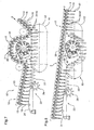
- FIGS. 4, 5, 7 and 8 show further embodiments of the device 10 according to the invention or the inventive method, which differs from the embodiments in the FIGS. 1 to 3 essentially differ in that the grippers 14 of the conveyor 12 at the assignment to the support members 34 are opened, the printed products 16 on the Support elements 34 are stored and the gripper 14 then from the printed products 16 and the Support elements 34 away via the connecting device 36 away. Behind the stapler 38, the gripper 14 of the same transporter 12 again with the now stapled printed products 16 on the support elements 34 brought together The gripper 14 of same transporter 12 take the now stapled supported by the support members 34 Print products 16 and promote them in the direction of F.
- FIGS. 4 and 5 also differs from that in FIG. 1 shown device 10 by the geometry of the upper tower of the circulation 32th Instead of the To aim transporter 12 and then open in an approximately horizontal course, such as In FIG. 1, the upper run 50 in FIG. 4 deviates downstream of the allocation region 31 with respect to FIG Feed back 12, then about in a horizontal conveyor line in the area of Connecting device 36 and for the return of the printed products 16 to the Transporter 12 again strive for this downstream of the connecting device 36. On this way, space is created for the connection device 36 and the transport path of the Transporteurs 12 experiences less major deflections. Unlike the embodiment, As shown in FIGS. 2 and 3, it is in the example shown here in FIGS.
- the opening device 22, the circulation 32 and the connecting device 36 by Lowering move out of the transport path of the printed products 16, if the Workstation "Connect at the feed dog" should be deactivated.
- the situation with the deactivated workstation is shown in Fig. 5.
- the lowering can again pneumatic, electrically or hydraulically done for each of these elements individually or via a common machine frame. In this case, the grippers do not contact the printed products 16 In this case, it is necessary for the grippers 14 to remain closed.
- the slide control must be adjusted accordingly.
- One above the connecting device 36 arranged cover 48 prevents it during the transport of the printed products 16 on the Connecting device 36 can come to complications.
- FIG. 6 shows a further embodiment of the device 10 according to the invention, which essentially corresponds to those of FIGS. 2 and 3, the support members 34 are as in the embodiment of Figs. 2 and 3 in a wheel-shaped arrangement 44 about a central Rotation axis B moves on a circular path K.
- the printed products 16 at their respective flower 20 and gripped by the grippers 14 on the Rotationsheftapparat 38 in the conveying direction F.
- the flower 20 opposite fold 18 of each printed product 16 is the Following gravity downwards.
- the support members 34 of the wheel-shaped arrangement 44 are formed in this example sword and are before the stapling laterally inserted above between the tabloid sides of the flexible sheet products.
- the opening device is unnecessary 22. If the stapling operation should not be performed, it is possible the rotary stapler 38th and / or shut the wheel-shaped assembly 44 and / or from the transport of the Remove transporters 12.
- FIG. 7 shows an embodiment which is essentially that of FIGS. 4 and 5 corresponds, except that the upper run 50 in this embodiment viewed in section from the Deflection pulleys from an approximately straight line describing the space for the connecting device 36 to win the transport path of the carrier 12 is configured corresponding curved.
- the opposite principle is now realized.
- the Embodiment corresponds again substantially to that of FIGS. 4 and 5, except that here the transport path of the carrier 12 straight across the connecting device 36 away leads and the geometry of the upper run 50 of the circulation 32 a correspondingly larger Curvature has.
- the radius of curvature of the strand 50 to the radius be adapted to the stapling heads 40 - or in other connecting device 36, such. one Ultrasonic device the sonotrodes, etc. - describe. By this adaptation is the common way of supporting elements and associated stitching heads, sonotrodes etc longer, what has an advantageous effect on the quality of the connection.
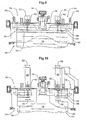
- a support member 34 is shown with benders 42 according to the prior art, as shown in Principle e.g. already in the European patent application no. 03025534, filed on 7. November 2003 with Swiss Priority No. 2002 1886/2 of 9 November 2002 in FIG. 7
- the support element 34 is configured in the form of a saddle 46, which in the middle a Recess 70, so that the deposited on the saddle 46 printed products by a Gripper 14 can be easily taken or so that they never free of the grippers 14 must be given.
- the Umbieger 42 are integrated by means of a in the support member 34 Bender 57 actuated.
- the clincher 57 is on the printed products 16 opposite side of the support members 34 are arranged.
- the support element 34 comprises in their lateral end portions 64 of the support members 34 pivotable about axes of rotation 66 Lever means 68, each with two opposing lever arms, which on a acting support member 72 extending parallel to the longitudinal extent of the support member 34.
- Lever means 68 each with two opposing lever arms, which on a acting support member 72 extending parallel to the longitudinal extent of the support member 34.
- On the support member 72 are two spaced Umbieger 42 supported so that they can interact with the stitching heads 40 of an associated stapling device 38. With help the stitching heads 40 are known to wire staples through on the support elements lying printed products 16 encountered.
- the lever device 68 is stage-controlled (arrow 80) actuated and presses when pressed the Umbieger 42 so against the stitching heads 40 that the protruding wire ends are bent by the clincher 42.
- the Stapling apparatus 38 and the support members 34 as shown in Fig. 10, according to the invention so developed further, that now the staple can be adapted to different paper sizes.
- At least two support elements 62 are provided instead of the saddle 46, each one Stabilize Umbieger 42 and provide support for the stored printed products 16.
- the benders 42 are stage-controlled by means of a lever device 68 (arrow 80). actuated.
- a lever device 68 arrow 80
- pivotable lever 68 directly to the bender 42 a.
- the lever devices 68 are synchronized during operation but individually controlled by scenes.
- the Umbieger 42 with their lever means 68 are on a support (indicated by arrows 60) parallel to Longitudinal extent of the support member 34 movably arranged To the interaction with the To ensure stapling heads 40, these are also parallel to the longitudinal extent of the Support member 34 movable.
- each associated stitching heads 40 and bender 42 together are movable parallel to the longitudinal extent of the support member 34.
- the stapling heads 40 may e.g. parallel to the longitudinal extent of Support member 34 are moved by the support disks 39 on the axis of the Rotationshefters 38 are displaceable in the axial direction.
- a common shift with the Umbieger 42 associated with the stitching heads 40 of a support disk 39 is then carried out Connection of the bender 42 with the support plate 39, for example via a Connection bar (not shown).
- the Umbieger 42 and the stitching heads 40 and Tragusionn 39 can also independently of each other parallel to the longitudinal extent of the support member 34th be movable; the stitching heads 40 on a first support (e.g., the axle) the rotary stapler) and the benders 42 on a second carrier, which in Fig. 10 by the Arrows 58 is indicated. It is understood that in such an embodiment parallel to Longitudinal extent of the support member 34 is not mandatory with two stitches along the fold 18th a printed product 16 must be worked. There may be one, two, or more stitches, ever as needed and width of the printed product 16 in the longitudinal extent of the support member 34th be made. These are on the carriers accordingly one, two or more Umbieger 42 with their lever devices 68 and stitching heads 40 or support disks 39 with stitching heads 40 provided.
- stapling with staples also other methods of connection and Work steps can be performed on the feed dog.
- a Adhesive connection of the printed products 16 are produced.
- the device 10 according to the invention is then instead of a stapling apparatus 38 with a corresponding device for adhesive tack, as disclosed, for example, in EP0662440 and EP0628429. That too Connecting by means of ultrasound is conceivable on the conveyor.
- an apparatus for Ultrasonic bonding such as e.g. in EP390733 and EP0390734, instead of the Stapling device 38 or the device for Klebheften use.
- the support elements 34 of Circulation 32 and the wheel-shaped arrangement 44 are then designed accordingly.
- Another possible step that can be performed on the feed dog 12 is the Plug in.
- Stacks formed as described in EP1254857, in Printed products 16 are inserted from below by the conveyor via a device, as described in FIGS. 12 and 45 of EP1254857.
- the procedure is then carried out as described in paragraph 46 of EP1254857, wherein instead of the cover sheet transported by the grippers 14 of the inventive device Printed products 16 placed over the stacks to be inserted and then together with the Stacking by the gripper 14 of the same transporter 12 again taken and transported become.
- the printed products 16 can, for example, in an antecedent Work step has already been connected to the feed dog by stitching, gluing or ultrasound be.
- the device according to the invention is in the area in which it is inserted is then simply supplemented by a device as shown in EP1254857 It is clearly that thus supplements and precursors etc. can be inserted without problems.
- EP1254857 in FIG Device it is not difficult for a person skilled in the art to see that in EP1254857 in FIG Device to use, for example. one more folded or several in the fold on top of each other laid, folded sheet with their fold advancing from below into the, in the grippers 14 of the according to the invention, to insert printed products 16.
- the way inserted printed sheets can in turn already together by stapling, gluing etc. be connected to each other. After inserting this sheet, it is possible with the same transporter to get to another workstation in which the inserted Printed sheet then e.g. with the existing in the grippers 14 printed products 16 be connected by ultrasound, gluing or another connection method.
- the transporter according to the invention further products from rounds 34 or collecting drums.
- cutting stations can also be provided. These can, however, like the others Workstations also, in a simple and cost-effective manner removed from the transport route or, if necessary, be reintroduced into the transport path of the printed products 16.
- inventive device 10 of the Transporter 12 are guided in a meaningful way successive workstations, wherein the workstations the end of a Schuppestromes. Connecting stations (stapling, gluing, Ultrasound etc), the end of a collection or insertion path, a device according to FIG. 12, EP1254857 etc. can be.
- workstations for example, by lowering, lifting, pivoting removed from the transport and the Support elements in the circulations or in the wheel-shaped arrangements and the stitching heads, etc. are adaptable to paper size, great flexibility in the use of the entire Reach the plant.
Landscapes
- Engineering & Computer Science (AREA)
- Mechanical Engineering (AREA)
- Textile Engineering (AREA)
- Folding Of Thin Sheet-Like Materials, Special Discharging Devices, And Others (AREA)
- Collation Of Sheets And Webs (AREA)
- Feeding Of Articles By Means Other Than Belts Or Rollers (AREA)
- Packaging Of Special Articles (AREA)
- Sewing Machines And Sewing (AREA)
- Treatment Of Fiber Materials (AREA)
- Supplying Of Containers To The Packaging Station (AREA)
- General Factory Administration (AREA)
- Threshing Machine Elements (AREA)
- Auxiliary Devices For And Details Of Packaging Control (AREA)
- Lining Or Joining Of Plastics Or The Like (AREA)
- Attitude Control For Articles On Conveyors (AREA)
- Intermediate Stations On Conveyors (AREA)
- Separation, Sorting, Adjustment, Or Bending Of Sheets To Be Conveyed (AREA)
Abstract
Description
Die Erfindung liegt auf dem Gebiet der Fördertechnik und betrifft ein Verfahren und eine Vorrichtung zum Transportieren und allfälligen Bearbeiten von flexiblen flächigen Produkten, insbesondere von Druckprodukten, gemäss den Merkmalen des Oberbegriffs des Patentanspruches 1 und den Merkmalen des Oberbegriffs des Anspruches 9.The invention is in the field of materials handling and relates to a method and a Device for transporting and possibly processing flexible flat products, in particular of printed products, according to the features of the preamble of claim 1 and the features of the preamble of claim 9.
In der Fördertechnik und insbesondere der Fördertechnik für Druckereierzeugnisse, ist es bekannt, flexible flächige Gegenstände bzw. Druckprodukte mit Hilfe von Greiftransporteuren zu fördern. insbesondere werden die Produkte von einer Arbeitstation zu einer nächsten Arbeitsstation mit Hilfe von solchen Greiftransporteuren gefördert. Jeder Greiftransporteur ist dabei in der Regel separat angetrieben und gesteuert. Dies erfordert entsprechend viele Antriebsaggregate und Steuerungseinrichtungen, was einen entsprechend hohen Investitions- und Wartungsaufwand nach sich zieht.In conveyor technology and in particular conveyor technology for printed products, it is known to promote flexible flat objects or printed products with the help of Greiftransporteuren. In particular, the products are transported from one workstation to another workstation Encouraged assistance from such gripping transporters. Each Greiftransportor is usually there driven and controlled separately. This requires a corresponding number of drive units and Control devices, resulting in a correspondingly high investment and maintenance costs pulls.
Arbeitsstrecken mit mehreren Arbeitsstationen, bei denen der Transport zwischen den Arbeitsstationen mit solchen Greiftransporteuren erfolgt, sind zudem recht unflexibel in ihrer Nutzung. Soll ein Arbeitsschritt ausgelassen werden, so muss eine neue Transportstrecke an dieser Arbeitsstation vorbei oder, falls die Arbeitsstation aus der Arbeitsstrecke entfernt wird, eine den Raum der Arbeitsstation überbrückende Transportstrecke mit einem Greiftransporteur aufgebaut werden. Eine Änderung in der Bearbeitung kann somit zeit- und kostenintensiv sein.Working distances with several workstations where the transport between the Workstations with such Greiftransporteuren done, are also quite inflexible in their Use. If a work step should be omitted, so must a new transport route at this Workstation over or, if the workstation is removed from the work area, a the Room of workstation bridging transport route with a grabber transporter built become. A change in the processing can thus be time consuming and costly.
Beispiele für derartige, unflexible Arbeitsstrecken in EP 0762950 und GB 5861 offenbart. In GB 5861 wird das zu beschneidende Druckprodukt durch die Greifer eines Greiftransporteurs der Schneidstation zugeführt, an diese abgegeben und nach dem Beschneiden durch die Greifer des gleichen Transporteurs oder eines zweiten nachgeschalteten Greiftransporteurs von der Schneidstation wegtransportiert. In EP 0762950 werden die Druckprodukte für den Schneidprozess an Einspannklammern übergeben, um diese für den Schneidprozess zu stabilisieren und in einer fixen Position zu halten. Die Greifer des Greiftransporteurs bleiben während des Schneidprozesses den Druckprodukten in den Einspannklammern zugeordnet, so dass die Druckprodukte von jeweils denselben Greifern der Schneidestation zugeführt und auch wieder von dieser weggeführt werden. In beiden Vorrichtungen sind die Schneidstationen fixer Bestandteil der Transportvorrichtung. Den heutigen Anforderungen an eine schnelle Umstellung der Produktion z.B. von grossen Tageszeitungen auf Wochenmagazine, Webeprospekte und auf verschiedene Zeitungen, Zeitschriften etc. können solche Vorrichtungen nicht oder nur bedingt gerecht werden.Examples of such inflexible working ways are disclosed in EP 0762950 and GB 5861. In GB 5861, the print product to be trimmed is gripped by the gripper of a gripper transporter Cutting station supplied, delivered to this and after trimming by the gripper of the same transporter or a second downstream Greiftransporteurs of the Cutting station transported away. EP 0762950 describes the printed products for the cutting process passed to clamps to stabilize them for the cutting process and in a hold fixed position. The grippers of the gripper transporter remain during the cutting process associated with the printed products in the gripping clamps, so that the printed products of each supplied to the same grippers of the cutting station and also led away from it again. In both devices, the cutting stations are a fixed part of the transport device. The Today's requirements for a rapid change of production e.g. from big ones Daily newspapers on weekly magazines, web brochures and various newspapers, Magazines, etc., such devices can not or only partially meet.
Aufgabe der vorliegenden Erfindung ist es daher, eine Vorrichtung und ein Verfahren zur Verfügung zu stellen, mit dem der Transport und eine allfällige Bearbeitung von flächigen flexiblen Produkten in kostengünstiger und flexibler Art ausgeführt werden können.The object of the present invention is therefore to provide a device and a method for To provide, with the transport and any processing of flat flexible Products in a cost effective and flexible way.
Diese Aufgabe wird gelöst durch ein Verfahren bzw. eine Vorrichtung gemäss den Merkmalen der Patentansprüche 1 und 9.This object is achieved by a method or a device according to the features of Claims 1 and 9.
Bei dem erfindungsgemässen Verfahren bzw. auf der efindungsgemässen Vorrichtung werden die zu transportierenden flexiblen flächigen Produkte, insbesondere von Druckprodukten, vom gleichen Greiftransporteur an eine Arbeitsstation hin und von dieser Arbeitsstation auch wieder weg gefördert, wobei mit Hilfe einer Steuerungseinrichtung jeweils eine logische Zuordnung zwischen flexiblen flächigen Produkten und Greifern des Greiftransporteurs erfolgt. Die Arbeitsstation ist dabei je nach Bedarf in den Transportweg einführbar oder daraus entfernbar. Auf diese Weise lassen sich die Investitions- und Wartungskosten auf einen einzigen Greiftransporteur reduzieren und das Arbeitsverfahren flexibilisieren. Die flexiblen flächigen Produkte können dabei von den Greifern des Transporteurs an der Blume oder am Falz gegriffen sein.In the inventive method or on the device according to the invention the to be transported flexible sheet products, in particular of printed products, from the same Greiftransportor to a workstation and from this workstation again away promoted, with the aid of a control device in each case a logical association between flexible flat products and grippers of Greiftransporturs takes place. The workstation is as required in the transport path insertable or removable. In this way The investment and maintenance costs can be reduced to a single gripper transporter and make the work process more flexible. The flexible sheet products can be used by the Gripper of the transporter to be grasped at the flower or at the fold.
Besonders einfach ist diese Steuerung zu realisieren für den Fall, dass die logische Zuordnung darin besteht, dass derselbe Greifer, der ein flexibles flächiges Produkt zu der Arbeitsstation hin gefördert hat, dieses flexible flächige Produkt auch von der Arbeitsstation wieder weg fördert.This control is particularly easy to implement in the event that the logical assignment in it There is the same gripper that conveys a flexible sheet product toward the workstation has also promoted this flexible sheet product away from the workstation.
Dabei ist es am einfachsten, wenn der Greifer während der Bearbeitung des flexiblen flächigen Produktes mit dem flexiblen flächigen Produkt synchron mitgeführt wird, wobei die Steuerung der Greifer (14), insbesondere eine Steuerkulisse für die Greifer im Bereich der Bearbeitung, variabel so einstellbar ist , dass die Greifer für die Bearbeitung der flexiblen flächigen Produkte geöffnet werden können oder auch geschlossen bleiben können. Geschlossene Greifer sind vor allem dann sehr nützlich, wenn z.B. als Druckprodukte mehrere als Tabloid gefaltete Bögen in welche Beilagen eingesteckt sind, z.B. durch Heften oder Kleben miteinander verbunden werden sollen.It is easiest if the gripper during processing of the flexible surface Product is synchronously carried with the flexible sheet product, wherein the control of Gripper (14), in particular a control link for the gripper in the field of processing, variable so is adjustable, that opens the gripper for the processing of flexible sheet products can be or even be closed. Closed grippers are especially then very useful if e.g. as printed products several tabloid folded sheets in which side dishes are inserted, e.g. by stitching or gluing together.
Die Steuerungseinrichtung ist aber auch in der Lage das Verfahren so zu Steuern, dass durch die logische Zuordnung von Greifern und flexiblen flächigen Produkten zueinander, ein Greifer, der ein flexibles flächiges Produkt zu einer Arbeitsstation hin gefördert hat, ein anderes flexibles flächiges Produkt von der Arbeitsstation weg fördert. Auf diese Weise können Geschwindigkeitsunterschiede beherrscht werden.The control device is also able to control the method so that by logical assignment of grippers and flexible flat products to each other, a gripper, the one flexible flat product has promoted to a workstation, another flexible planar Promote product away from the workstation. In this way can speed differences be mastered.
Wo dies für die Bearbeitung notwendig ist, werden die flexiblen flächigen Produkte für die Bearbeitung durch ein Stützelement abgestützt. Je nach dem, ob die flexiblen flächigen Produkte von den Greifern des Transporteurs an der Blume oder am Falz gegriffen sind, werden die Produkte entweder mit dem Falz von oben auf den Stützelementen abgelegt oder die Stützelementen werden zwischen die Produkte eingeführt und stützen die flexiblen flächigen Produkte an ihrem gegen unten ausgerichteten Falz.Wherever this is necessary for processing, the flexible sheet products for the Machining supported by a support element. Depending on whether the flexible sheet products are grasped by the transporter's grippers at the flower or at the fold become the products either deposited with the fold from above on the support elements or the support elements are introduced between the products and support the flexible laminar products at theirs against down-aligned fold.
Der Transport kann über mehrere Arbeitsstationen führen, die mit Bezug auf den Transportweg des Greiftransporteurs stromab hintereinander und/oder in parallel geführten, über Weichen miteinander verbunden Strängen des Greiftransporteurs angeordnet sein können.The transport can lead across several workstations that are related to the transport path of the Greiftransporteurs downstream one behind the other and / or in parallel, over points interconnected strands of Greiftransportor can be arranged.
Dadurch, dass die Arbeitsstationen durch Verschwenken, hydraulisches, elektrisches oder pneumatisches Absenken oder Anheben aus dem Transportweg des Greiftransporteurs entfernbar sind, kann die Arbeitsstrecke sehr flexibel gestaltet werden und es ist ohne grossen Aufwand möglich, Arbeitsschritte auszulassen oder hinzuzufügen.The fact that the workstations by pivoting, hydraulic, electric or pneumatic lowering or lifting removable from the transport path of the Greiftransporteurs are, the working distance can be made very flexible and it is easy possible to skip or add work steps.
Ist die efindungsgemässe Vorrichtung so ausgestaltet, dass der Transporteur mit seinem Transportweg über der Arbeitsstation hinweg geführt ist, so umfasst die Arbeitsstation vorzugsweise eine Abdeckung. Für den Fall, dass der entsprechende Arbeitsschritt ausgelassen wird, können so Probleme beim Fördern der flexiblen flächigen Produkte über die Arbeitsstation hinweg vermieden werden.Is the device according to the invention designed such that the transporter with his Transport path is routed across the workstation, so includes the workstation preferably a cover. In the event that the corresponding step is omitted Thus, problems can occur when conveying the flexible sheet-like products via the workstation be avoided.
Als Arbeitsstationen können Verbindungsvorrichtungen - insbesondere Heftapparate, Ultraschalleinrichtungen, Vorrichtungen zum Klebheften - und/oder Vorrichtungen zum Einstecken von flexiblen flächigen Produkten, und/oder das Ende einer Sammel- bzw. Sammelheftstrecke und/oder das Ende einer Einsteck- und/oder Einsteckheftstrecke vorgesehen sein.As workstations connection devices - in particular staplers, Ultrasonic devices, devices for adhesive bonding and / or devices for Inserting flexible sheet products, and / or the end of a collection or Sammelheftstrecke and / or the end of a plug-in and / or Einsteckheftstrecke provided be.
Weitere Ausführungsformen des Verfahrens und der Vorrichtung sind in den weiteren abhängigen Ansprüchen beschrieben.Further embodiments of the method and the device are dependent in the further Claims described.
Im Folgenden wird die Erfindung anhand von Figuren beispielhaft erläutert. Gleiche Gegenstände sind in den Figuren grundsätzlich mit gleichen Bezugszeichen gekennzeichnet Die Figuren zeigen rein schematisch:
- Fig. 1
- eine erste Ausführungsform der erfindungsgemässen Vorrichtung zum Bearbeiten von Druckprodukten am Transporteur;
- Fig. 2
- eine zweite erfindungsgemässe Vorrichtung zu Bearbeiten von Druckprodukten am Transporteur in einem ersten Arbeitszustand;
- Fig. 3
- die Vorrichtung aus Fig. 2 in einem zweiten Arbeitszustand;
- Fig. 4
- eine dritte Ausführungsform der erfindungsgemässen Vorrichtung;
- Fig. 5
- die Vorrichtung aus Fig. 4 in einem zweiten Arbeitszustand;
- Fig. 6
- eine vierte Ausführungsform der erfindungsgemässen Vorrichtung;
- Fig. 7 und 8
- zwei weitere Ausführungsformen der erfindungsgemässen Vorrichtung;
- Fig. 9
- im Detail ein Stützelement mit Umbiegern gemäss Stand der Technik;
- Fig. 10
- eine erfindungsgemässes Stützelement mit Umbiegern.
- Fig. 1
- a first embodiment of the inventive device for processing printed products at the conveyor;
- Fig. 2
- a second device according to the invention for processing printed products on the conveyor in a first working state;
- Fig. 3
- the device of Figure 2 in a second working state.
- Fig. 4
- a third embodiment of the inventive device;
- Fig. 5
- the device of Figure 4 in a second working state.
- Fig. 6
- A fourth embodiment of the inventive device;
- FIGS. 7 and 8
- two further embodiments of the inventive device;
- Fig. 9
- in detail, a support element with benders according to the prior art;
- Fig. 10
- an inventive support element with benders.
Die in den Figuren 1 bis 8 dargestellten Beispiele beziehen sich auf den Transport von
typischerweise in Tabloidform gefalteten Druckbogen die einzeln oder zu mehreren übereinander
gelegt mittels eines Greiftransporteurs 12 transportiert werden und unabhängig von ihrer Anzahl
von Einzelbogen/Lagen der Einfachheit halber als Druckprodukt 16 bezeichnet werden. Es versteht
sich dass auch andere flexiblen flächigen Produkte 16 auf diese Art transportiert und bearbeitet
werden können. In den gezeigten Beispielen 1 bis 8 ist ausserdem der Einfachheit halber als
Arbeitsstation 2 jeweils einen Heftapparat 38 dargestellt Wie aber weiter unten ausgeführt wird,
ist es möglich je nach gewünschtem Arbeitsergebnis auch andere Apparate bzw. Vorrichtungen als
Arbeitsstationen 2 vorzusehen.The examples shown in FIGS. 1 to 8 relate to the transport of
typically folded in Tabloidform sheet single or several on top of each other
can be transported by means of a
Figur 1 zeigt eine erfindungsgemässe Vorrichtung 10 mit einem Greiftransporteur 12, der an einem
endlos umlaufenden Förderorgan 15 Greifer 14 transportiert Die Greifer 14 sind mit Greifbacken
13 ausgestattet, mit denen in üblicher Weise aus mehreren gefalteten Bogen bestehende
Druckprodukte 16 ergriffen werden können. In dem hier gezeigten Beispiel werden die
Druckprodukte 16 an ihrem jeweiligen Falz 18 ergriffen und von den Greifern 14 in Förderrichtung
F transportiert. Die dem Falz 18 gegenüberliegende Blume 20 jedes Druckproduktes 16 ist der
Schwerkraft folgend nach unten ausgerichtetFIG. 1 shows a
Weiter weist die erfindungsgemässe Vorrichtung 10 in diesem Beispiel eine Öffnungsvorrichtung
22 mit einem umlaufenden Auslenkband 24 einen sich daran anschliessenden Öffnungsrad 26
und einer sich an das Öffnungsrad 26 anschliessenden Wendel 30 auf. Weitere Elemente der hier
gezeigten erfindungsgemässen Vorrichtung 10 sind eine Verbindungsvorrichtung 36, die in diesem
Beispiel als Rotationsheftapparat 38 ausgestaltet ist sowie einen Umlauf, der an seinem endlos
umlaufenden Förderorgan 15' in definiertem Abstand zueinander Stützelemente 34 aufweist. Bei
dem Heftapparat 38 handelt es sich um einen üblichen Rotationshefter der auf einer Tragscheibe
39 mehrere in gleichmässigem Abstand angeordnete Heftköpfe 40 aufweist Solch ein Heftapparat
ist z.B. in WO 02/36474 in Fig. 8 oder auch in EP0606555 und in EP0691215 beschrieben. Die
Stützelemente 34 des Umlaufes 32 weisen Umbieger 42 auf, die zum Ausführen eines
Heftvorganges mit den Heftköpfen 40 des Heftapparates 38 zusammenwirken. Es können aber
auch Umbieger vorgesehen sein, die von den Stützelementen separiert angeordnet und von diesen
unabhängig bewegbar sind.Furthermore, the
Erfindungsgemäss werden nun von dem Transporteur 12 der erfindungsgemässen Vorrichtung 10
direkt von der Rotation, von einer Puffereinrichtung oder einer beliebigen anderen
Fördereinrichtung Druckprodukte 16 übernommen und einer Arbeitsstation 2 zugefördert. Die
Druckprodukte können dabei aus einem oder mehreren Einzelbogen/Lagen, und allenfalls in
Tabloidform gefalteten und übereinander gelegten Druckbogen bestehen (hier nicht dargestellt).
Der Transporteur 12 transportiert in diesem Beispiel die Druckprodukte 16 in den Bereich der
Öffnungsvorrichtung 22, wobei die Blumen der Druckprodukte 16 auf das umlaufende
Auslenkband 24 der Öffnungsvorrichtung 22 auflaufen, durch welches sie in Förderrichtung F
ausgelenkt werden, wie dies aus Fig. 1 ersichtlich ist Durch das sich anschliessende Öffnungsrad
26 werden die Druckprodukte 16 blumenseitig geöffnet und beim Weitertransport in
Förderrichtung F über der Wendel 30 offen gehalten, In einem Zuordnungsbereich 31 werden die
geöffneten Druckprodukte 16 auf den Stützelementen 34 des Umlaufes 32 abgelegt. In dem hier
gezeigten Beispiel werden dazu die Greifer 14 nicht aktiv geöffnet sondern bleiben geschlossen
und die Stützelemente 34 dringen gegen die Klemmwirkung der Greiferbacken 13 zwischen die
Greifbacken 13 ein. Es besteht natürlich auch die Möglichkeit, das Eindringen durch ein
angepasstes Öffnen der Greifer 14 zB. kulissengesteuert zu unterstützen.According to the invention, the
Die Abstände der Greifer 14 am Transporteur 12 sowie die Abstände der Stützelemente 34 des
Umlaufes 32 und deren Geschwindigkeit sind entsprechend aufeinander abgestimmt, so dass eine
problemlose Zuordnung der Greifer 14 - und mit ihnen die Druckprodukte 16 - zu den
Stützelementen 34 erfolgen kann und die Greifer 14 mit den Stützelementen 34 in Förderrichtung
F im Wesentlichen synchron mitlaufen können. Im Bereich des Heftapparates 38 erfolgt in üblicher
Weise eine Klammerheftung, wobei die in den Stützelementen 34 integrierten Umbieger 42 für das
Schliessen der durch die Heftköpfe 40 in die Druckprodukte 16 eingebrachten Drahtklammern
sorgen. Es versteht sich, dass die Anordnung der Heftköpfe auf der Tragscheibe 39 des
Rotationsheftapparates 38 sowie die Rotationsgeschwindigkeit der Tragscheibe 39 abgestimmt
sind auf die Abstände der Greifer 14 bzw. der Stützelemente 34 und die Fördergeschwindigkeit in
Richtung F.The distances between the
Sind die Umbieger nicht in die Stützelemente 34 integriert, werden diese zum Schliessen der
Heftklammern den Druckprodukten 16 separat zugeführt und, wenn nötig, über einen
entsprechenden Abschnitt des Bewegungsweges der Druckprodukte 16 mit diesen mitgeführt, so
dass eine qualitativ anspruchsvolle Heftung erfolgen kann.Are the Umbieger not integrated into the
Beim eigentlichen Heftvorgang d. h. beim Einbringen der Heftklammern durch die Heftköpfe 40 in
die Druckprodukte 16 und das anschliessende Umbiegen der Drahtenden zu geschlossenen
Heftklammern ist es möglich die Greifer 14 geschlossen zu halten oder aber auch zu öffnen. Das
Geschlossenhalten der Greifer ist vorteilhaft, wenn das Heften beispielsweise erfolgt, nachdem
bereits Beilagen in die Druckprodukte 16 eingebracht wurden. Das Einstecken ist weiter unten
beschrieben.During the actual stapling process d. H. during insertion of the staples by the stitching heads 40 in
the printed
In den Figuren 2 und 3 ist eine weitere Ausführungsform der erfindungsgemässen Vorrichtung 10
dargestellt, die im Wesentlichen der Ausführungsform aus Fig. 1 entspricht. Im Gegensatz zu der
Ausführungsform in Fig. 1 sind in den Beispielen der Fig. 2 und 3 die Stützelemente 34 nicht in
einem Umlauf 32 an einem endlos umlaufenden Förderorgan 15' angeordnet, sondern sie werden
in einer radförmigen Anordnung 44 um eine zentrale Rotationsachse B auf einer Kreisbahn K
bewegt Die Stützelemente 34 können in Form von bekannten Satteln oder Auflagen ausgebildet
sein oder aber nur durch entsprechend stabil ausgebildete Umbieger (vgl. Fig. 9 und 10). Das
gleiche gilt auch für die Stützelemente 34 aus dem Ausführungsbeispiel der Fig. 1. Das
erfindungsgemässe Verfahren wie es oben im Zusammenhang mit der Ausführungsform der Fig. 1
beschrieben worden ist, läuft in dem in Fig. 2 gezeigten Beispiel analog ab.FIGS. 2 and 3 show a further embodiment of the
Soll der Heftvorgang nicht ausgeführt werden, so ist es möglich den Heftapparat 34 sowie die
Öffnungsvorrichtung 22 und die radförmige Anordnung 44 aus dem Transportweg des
Transporteurs 12 zu entfernen, wie dies in Fig. 3 dargestellt ist. In dem hier gezeigten Beispiel wird
der Heftapparat 38 pneumatisch oder hydraulisch (Pfeil H) angehoben, während die radförmige
Anordnung 44 und die Öffnungsvorrichtung 22 um die Drehachse A nach unten verschwenkt und
so aus dem Transportweg entfernt werden (Pfeil 5). Öffnungsvorrichtung 22 und radförmige
Anordnung 44 sind hierzu auf einem gemeinsamen Maschinengestell (nicht dargestellt)
angeordnet, das um die Achse A verschwenkbar gelagert ist Es versteht sich, dass je nach
Platzverhältnissen auch ein seitliches Verschwenken oder ein verschwenken in beliebige andere
Richtung aus dem Transportweg hinaus möglich ist Statt einer pneumatischen oder hydraulischen
Anhebung kann auch eine Absenkung des Heftapparates 38 vorgesehen sein. Auch ist es denkbar
das Anheben oder Absenken elektrisch zu bewerkstelligen, Ebenso ist es denkbar den Heftapparat
38 durch solche elektrischen, pneumatischen oder hydraulischen Mittel zu Verschwenken, sowie die
Öffnungsvorrichtung 22 und die radförmige Anordnung 44 anzuhaben oder abzusenken anstatt
sie zu verschwenken.If the stapling operation is not performed, it is possible the
In den Fig. 4, 5, 7 und 8 sind weitere Ausführungsformen der erfindungsgemässen Vorrichtung 10
bzw. des erfindungsgemässen Verfahrens dargestellt, die sich von den Ausführungsformen in der
Fig. 1 bis 3 im Wesentlichen dadurch unterscheiden, dass die Greifer 14 des Transporteurs 12 bei
der Zuordnung zu den Stützelementen 34 geöffnet werden, die Druckprodukte 16 auf den
Stützelementen 34 ablegt werden und die Greifer 14 dann von den Druckprodukten 16 und den
Stützelementen 34 entfernt über die Verbindungsvorrichtung 36 hinweggeführt werden. Hinter
dem Heftapparat 38 werden die Greifer 14 des gleichen Transporteurs 12 wieder mit den nun
gehefteten Druckprodukten 16 auf den Stützelementen 34 zusammengeführt Die Greifer 14 des
gleichen Transporteurs 12 ergreifen die nun gehefteten durch die Stützelemente 34 abgestützten
Druckprodukte 16 und fördern sie in Richtung F weiter. Dabei ist es abhängig von den jeweiligen
Bedingungen möglich, dass der Greifer 14 des Transporteurs 12 der ein Druckprodukt 16A auf
einem Stützelement 34 abgelegt hat, dieses Druckprodukt 16A nach der Heftstation 38 auch
wieder ergreift, oder aber dass dieser Greifer 14 ein anderes Druckprodukt 16B ergreift Ober eine
Steuereinheit (nicht dargestellt) der erfindungsgemässen Vorrichtug 10 wird die logische
Zuordnung der Greifer 14 des Transporteurs 12 zu den aus der Arbeitsstation 2 herauskommenden
Druckprodukte und in diesen Beispielen also zu den Stützelementen 34 des Umlaufes 32 oder
auch einer radförmigen Anordnung 44 vorgenommen.FIGS. 4, 5, 7 and 8 show further embodiments of the
Die in Fig. 4 und 5 gezeigte Ausführungsform unterscheidet sich ausserdem von der in Fig. 1
gezeigten Vorrichtung 10 durch die Geometrie des oberen Turms des Umlaufs 32. Statt dem
Transporteur 12 entgegenzustreben und dann in einen etwa horizontalen Verlauf zu münden, wie
in Fig. 1, weicht das obere Trum 50 in Fig. 4 stromab des Zuordnungsbereichs 31 gegenüber dem
Transporteur 12 zurück, um dann etwa in eine horizontale Förderstrecke im Bereich des
Verbindungsvorrichtung 36 überzugehen und für die Rückgabe der Druckprodukte 16 an den
Transporteur 12 diesem stromab der Verbindungsvorrichtung 36 wieder entgegenzustreben. Auf
diese Weise wird Raum geschaffen für die Verbindungsvorrichtung 36 und die Transportstrecke des
Transporteurs 12 erfährt weniger grosse Auslenkungen. Im Unterschied zu der Ausführungsform,
wie sie in Fig. 2 und 3 dargestellt ist, ist es in dem hier in den Fig. 4 und 5 gezeigten Beispiel
möglich, die Öffnungsvorrichtung 22, den Umlauf 32 und die Verbindungsvorrichtung 36 durch
Absenken (Pfeil H) aus dem Transportweg der Druckprodukte 16 herauszubewegen, wenn die
Arbeitsstation "Verbinden am Transporteur" deaktiviert werden soll. Die Situation mit der
deaktivierten Arbeitsstation ist in Fig. 5 dargestellt. Das Absenken kann wiederum pneumatisch,
elektrisch oder hydraulisch erfolgen und zwar für die genannten Elemente je einzeln oder via ein
gemeinsames Maschinengestell. Damit die Greifer in diesem Fall die Druckprodukte 16 nicht an
die Stützelemente 34 abgeben, ist es in diesem Fall nötig, dass die Greifer 14 geschlossen bleiben.
Die Kulissensteuerung ist entsprechend anzupassen. Eine über der Verbindungsvorrichtung 36
angeordnete Abdeckung 48 verhindert, dass es bei dem Transport der Druckprodukte 16 über die
Verbindungsvorrichtung 36 hinweg zu Komplikationen kommen kann. The embodiment shown in FIGS. 4 and 5 also differs from that in FIG. 1
shown
In Fig. 6 ist eine weitere Ausführungsform der erfindungsgemässen Vorrichtung 10 dargestellt, die
im Wesentlichen derjenigen aus den Fig. 2 und 3 entspricht, Die Stützelemente 34 werden wie in
der Ausführungsform von Fig. 2 und 3 in einer radförmigen Anordnung 44 um eine zentrale
Rotationsachse B auf einer Kreisbahn K bewegt. Im Gegensatz zu der Ausführungsform in Fig. 2
und 3, werden in dem hier gezeigten Beispiel die Druckerzeugnisse 16 an ihrer jeweiligen Blume
20 ergriffen und von den Greifern 14 über den Rotationsheftapparat 38 in Förderrichtung F
transportiert Der der Blume 20 gegenüberliegende Falz 18 jedes Druckerzeugnisses 16 ist der
Schwerkraft folgend nach unten ausgerichtet. Die Stützelemente 34 der radförmigen Anordnung
44 sind in diesem Beispiel schwertartig ausgebildet und werden vor dem Heftvorgang seitlich von
oben zwischen die Tabloidseiten der flexiblen flächigen Produkte eingeführt. Beim Heften durch
den Heftapparat 38 stützen sie den Falz 18 gegen die, in diesem Beispiel, beim Heften gegen
oben wirkende Kraft. Bei der hier gezeigten Ausführungsform erübrigt sich die Öffnungsvorrichtung
22. Soll der Heftvorgang nicht ausgeführt werden, so ist es möglich den Rotationsheftapparat 38
und/oder die radförmige Anordnung 44 stillzulegen und/oder aus dem Transportweg des
Transporteurs 12 zu entfernen.FIG. 6 shows a further embodiment of the
In Fig. 7 ist eine Ausführungsform dargestellt, die im Wesentlichen derjenigen aus den Fig. 4 und 5
entspricht, nur dass das obere Trum 50 in dieser Ausführungsform im Schnitt betrachtet von den
Umlenkrollen aus eine etwa gerade Linie beschreibt Um den Raum für die Verbindungsvorrichtung
36 zu gewinnen ist der Transportweg des Transporteurs 12 entsprechend gekrümmt ausgestaltet.FIG. 7 shows an embodiment which is essentially that of FIGS. 4 and 5
corresponds, except that the
In der in Fig. 8 gezeigten Ausführungsform ist nun das gegenteilige Prinzip verwirklicht. Die
Ausführungsform entspricht im Wesentlichen wieder derjenigen aus den Fig. 4 und 5, nur dass hier
der Transportweg des Transporteurs 12 geradlinig über die Verbindungsvorrichtung 36 hinweg
führt und die Geometrie des oberen Trums 50 des Umlaufs 32 eine entsprechend grössere
Krümmung aufweist. Vorteilhaft kann hier der Krümmungsradius des Trums 50 an den Radius
angepasst sein, den die Heftköpfe 40 - oder bei anderen Verbindungsvorrichtung 36, wie z.B. einer
Ultraschalleinrichtung die Sonotroden, etc. - beschreiben. Durch diese Anpassung ist der
gemeinsame Weg von Stützelementen und zugeordneten Heftköpfen, Sonotroden etc länger, was
sich vorteilhaft auf die Qualität der Verbindung auswirkt.In the embodiment shown in Fig. 8, the opposite principle is now realized. The
Embodiment corresponds again substantially to that of FIGS. 4 and 5, except that here
the transport path of the
Es versteht sich, dass bei einer etwas weniger kompakten Bauweise, als sie in den Figuren 7 und 8
dargestellt ist, die Steigungen für den Greifertransporteur 12 bzw. für das obere Trum 50 geringer
gehalten werden können unter in Kaufnahme einer grösseren Weglänge.It is understood that in a somewhat less compact design, as shown in Figures 7 and 8
is shown, the slopes for the
In Figur 9 ist ein Stützelement 34 mit Umbiegern 42 gemäss Stand der Technik gezeigt, wie sie im
Prinzip z.B. bereits in der europäischen Patenanmeldung Nr. 03025534, angemeldet am 7.
November 2003 mit Schweizer Priorität Nr. 2002 1886/2 vom 9. November 2002 in Fig. 7
dargestellt ist Das Stützelement 34 ist in Form eines Sattels 46 ausgestaltet, der in der Mitte eine
Aussparung 70 aufweist, so dass die auf dem Sattel 46 abgelegten Druckprodukte durch einen
Greifer 14 problemlos ergriffen werden können bzw. so, dass sie nie von den Greifern 14 frei
gegeben werden müssen. Die Umbieger 42 sind mit Hilfe einer in das Stützelement 34 integrierte
Umbiegeeinrichtung 57 betätigbar. Die Umbiegeeinrichtung 57 ist auf der den Druckprodukten
16 gegenüberliegenden Seite der Stützelemente 34 angeordnet. Das Stützelement 34 umfasst in
ihren seitlichen Endbereichen 64 der Stützelemente 34 um Drehachsen 66 schwenkbare
Hebeleinrichtungen 68 mit je zwei einander gegenüberliegenden Hebelarmen, die auf ein sich
parallel zur Längserstreckung des Stützelements 34 erstreckendes Tragelement 72 einwirken. Auf
dem Tragelement 72 sind zwei voneinander beabstandete Umbieger 42 derart abgestützt, dass sie
mit den Heftköpfen 40 eines zugeordneten Heftapparates 38 zusammenwirken können. Mit Hilfe
der Heftköpfe 40 werden bekanntermassen Drahtklammern durch die auf den Stützelementen
liegenden Druckprodukte 16 gestossen. Die Hebeleinrichtung 68 ist kulissengesteuert (Pfeil 80)
betätigbar und drückt bei Betätigung die Umbieger 42 so gegen die Heftköpfe 40, dass die
überstehenden Drahtenden von den Umbiegern 42 umgebogen werden.In Figure 9, a
Um die Einsatzmöglichkeiten der erfindungsgemässen Vorrichtung zu vergrössern, sind die
Heftapparatur 38 und die Stützelemente 34, wie in Fig. 10 gezeigt, erfindungsgemäss so
weiterentwickelt, dass nun die Heftung an verschiedene Papierformate angepasst werden kann. To increase the capabilities of the inventive device, the
Hierzu sind statt des Sattels 46 wenigstens zwei Stützelemente 62 vorgesehen, die je einen
Umbieger 42 stabilisieren und für eine Abstützung der abgelegten Druckprodukte 16 sorgen. Wie
in Fig. 9 sind die Umbieger 42 mit Hilfe einer Hebeleinrichtung 68 kulissengesteuert (Pfeil 80)
betätigbar. Statt über ein gemeinsames Tragelement 72 wirken aber jetzt die um ihre Drehachse
66 schwenkbaren Hebel 68 direkt auf die Umbieger 42 ein. Die Hebeleinrichtungen 68 werden
während des Betriebes synchron aber individuell durch Kulissen gesteuert. Die Umbieger 42 mit
ihren Hebeleinrichtungen 68 sind auf einem Träger (angedeutet durch Pfeile 60) parallel zur
Längserstreckung des Stützelements 34 bewegbar angeordnet Um das Zusammenwirken mit den
Heftköpfen 40 zu gewährleisten sind diese ebenfalls parallel zur Längserstreckung des
Stützelements 34 bewegbar.For this purpose, at least two
In dem in Fig. 10 gezeigten Beispiel sind die Heftköpfe und die Umbieger so miteinander
verbunden, dass die jeweils einander zugeordneten Heftköpfe 40 und Umbieger 42 gemeinsam
parallel zur Längserstreckung des Stützelements 34 bewegbar sind. Besteht die Heftapparatur aus
einem Rotationshefter 38 so können die Heftköpfe 40 z.B. parallel zur Längserstreckung des
Stützelements 34 verschoben werden, indem die Tragscheiben 39 auf der Achse des
Rotationshefters 38 in Achslängsrichtung verschiebbar sind. Eine gemeinsame Verschiebung mit
dem den Heftköpfen 40 einer Tragscheibe 39 zugeordneten Umbieger 42 erfolgt dann durch
Verbindung des Umbiegers 42 mit der Tragscheibe 39 beispielsweise über einen
Verbindungsbalken (nicht dargestellt). Die Umbieger 42 und die Heftköpfe 40 bzw. Tragscheiben
39 können aber auch unabhängig voneinander parallel zur Längserstreckung des Stützelements 34
bewegbar sein; die Heftköpfe 40 bzw. die Tragscheiben 39 auf einem ersten Träger (z.B. der Achse
des Rotationshefters) und die Umbieger 42 auf einem zweiten Träger, der in Fig. 10 durch die
Pfeile 58 angedeutet ist. Es versteht sich, dass bei einer solchen Ausgestaltung parallel zur
Längserstreckung des Stützelements 34 nicht zwingend mit zwei Heftungen entlang des Falzes 18
eines Druckproduktes 16 gearbeitet werden muss. Es können ein, zwei, oder mehr Heftungen, je
nach Bedarf und Breite des Druckproduktes 16 in Längserstreckung des Stützelements 34
vorgenommen werden. Dazu sind auf den Trägern entsprechend ein, zwei oder mehr Umbieger 42
mit ihren Hebeleinrichtungen 68 und Heftköpfe 40 bzw. Tragscheiben 39 mit Heftköpfen 40
vorzusehen.In the example shown in Fig. 10, the stitching heads and the clincher are so together
connected, that each associated stitching heads 40 and
Es ist klar, dass statt des Heftens mit Heftklammern auch andere Verbindungsverfahren und
Arbeitsschritte am Transporteur ausgeführt werden können. So kann beispielsweise auch eine
Klebeverbindung der Druckprodukte 16 hergestellt werden. Die erfindungsgemässe Vorrichtung 10
ist dann statt mit einer Heftapparatur 38 mit einer entsprechenden Vorrichtung zum Klebheften,
wie sie beispielsweise in EP0662440 und EP0628429 offenbart sind, ausgestattet. Auch das
Verbinden mittels Ultraschall ist am Transporteur denkbar. Entsprechend ist eine Vorrichtung zum
Ultraschallverbinden wie sie z.B. in EP390733 und EP0390734 offenbart ist, statt der
Heftapparatur 38 oder der Vorrichtung zum Klebheften einzusetzen. Die Stützelemente 34 des
Umlaufes 32 bzw. der radförmigen Anordnung 44 sind dann entsprechend ausgestaltet.It is clear that instead of stapling with staples also other methods of connection and
Work steps can be performed on the feed dog. For example, a
Adhesive connection of the printed
Ein weiterer möglicher Arbeitsschritt der am Transporteur 12 ausgeführt werden kann ist das
Einstecken. So können z.B. Stapel, die wie in EP1254857 beschrieben gebildet wurden, in
Druckprodukte 16 von unten eingesteckt werden, indem der Transporteur über eine Vorrichtung,
wie sie in Fig. 12 und Absatz 45 der EP1254857 beschrieben ist, hinweggeführt wird. Das
Verfahren wird dann so durchgeführt, wie dies in Absatz 46 der EP1254857 beschrieben ist, wobei
statt den Deckbogen die von den Greifern 14 der erfindungsgemässen Vorrichtung transportierten
Druckprodukte 16 geöffnet über die einzusteckenden Stapel gelegt und dann zusammen mit den
Stapeln durch die Greifer 14 desselben Transporteurs 12 wieder ergriffen und weiter transportiert
werden. Die Druckprodukte 16 können dabei beispielsweise auch in einem vorgängigen
Arbeitsschritt bereits am Transporteur durch Heften, Kleben oder Ultraschall verbundenen worden
sein. Zum Einstecken ist die erfindungsgemässe Vorrichtung in dem Bereich, in dem eingesteckt
werden soll, dann einfach durch eine Vorrichtung ergänzt, wie sie in EP1254857 gezeigt ist Es ist
klar, dass somit Beilagen und Vorprodukte etc. ohne Probleme eingesteckt werden können.Another possible step that can be performed on the
Für den Fachmann ist es aber auch nicht schwierig die in EP1254857 in Fig. 12 gezeigte
Vorrichtung zu nutzen, um zB. nochmals einen gefalteten oder mehrere im Falz übereinander
gelegte, gefaltete Druckbogen mit ihrem Falz voran von unten in die, in den Greifern 14 der
erfindungsgemässen Vorrichtung befindlichen, Druckprodukte 16 einzustecken. Die so
eingesteckten Druckbogen können ihrerseits bereits miteinander durch Heften, Kleben etc.
miteinander verbunden sein. Nach dem Einstecken dieser Druckbogen ist es möglich mit dem
gleichen Transporteur an eine weitere Arbeitsstation zu gelangen, in der die eingesteckten
Druckbogen dann z.B. mit den bereits in den Greifern 14 vorhandenen Druckprodukten 16
verbunden werden, sei es durch Ultraschall, Kleben oder eine andere Verbindungsmethode.
Natürlich lassen sich auch über übliche Sammelstrecken, wie Sammeltrommeln,
Sammelhefttrommeln, Einstecktrommeln etc. erstellte Produkte auf diese Weise mit den
Druckprodukten 16 in der erfindungsgemässen Vorrichtung 10 zusammenbringen.
Erfindungsgemäss ist es auch möglich mit dem erfindungsgemässen Transporteur weitere Produkte
von Umläufen 34 oder Sammeltrommeln abzugreifen. Als eine oder mehrere Arbeitsstationen
können freilich auch Schneidstationen vorgesehen sein. Diese können aber, wie die anderen
Arbeitsstationen auch, auf einfache und kostengünstige Weise aus der Transportstrecke entfernt
bzw. bei Bedarf wieder in den Transportweg der Druckprodukte 16 eingebracht werden.However, it is not difficult for a person skilled in the art to see that in EP1254857 in FIG
Device to use, for example. one more folded or several in the fold on top of each other
laid, folded sheet with their fold advancing from below into the, in the
Für den Fachmann ist klar, dass und in welcher Weise sich die oben beschriebenen Merkmale und
Beispiele der erfindungsgemässen Vorrichtung und des erfindungsgemässen Verfahrens sinnvoll
miteinander kombinieren lassen. So kann in der erfindungsgemässen Vorrichtung 10 der
Transporteur 12 über in sinnvoller Weise aufeinander folgende Arbeitsstationen geführt werden,
wobei die Arbeitsstationen das Ende eines Schuppestromes. Verbindungsstationen (Heften, Kleben,
Ultraschall etc), das Ende einer Sammel- oder Einsteckstrecke, eine Vorrichtung gemäss Fig. 12,
EP1254857 etc. sein können. Durch Weichen bzw. dadurch, dass die Arbeitsstationen
beispielsweise durch Absenken, Anheben, Verschwenken aus dem Transportweg entfernbar und die
Stützelemente in den Umläufen bzw. in den radförmigen Anordnungen sowie die Heftköpfe etc.
dem Papierformat anpassbar sind, lässt sich grosse Flexibilität in der Nutzung der gesamten
Anlage erreichen.It is clear to a person skilled in the art that, and in what way, the features described above and
Examples of the inventive device and the inventive method useful
let combine with each other. Thus, in the
Claims (15)
Priority Applications (1)
| Application Number | Priority Date | Filing Date | Title |
|---|---|---|---|
| PL05008056T PL1588971T3 (en) | 2004-04-22 | 2005-04-13 | Method and apparatus for handling of printed products |
Applications Claiming Priority (2)
| Application Number | Priority Date | Filing Date | Title |
|---|---|---|---|
| CH7072004 | 2004-04-22 | ||
| CH7072004 | 2004-04-22 |
Publications (3)
| Publication Number | Publication Date |
|---|---|
| EP1588971A1 true EP1588971A1 (en) | 2005-10-26 |
| EP1588971B1 EP1588971B1 (en) | 2008-10-01 |
| EP1588971B2 EP1588971B2 (en) | 2019-06-19 |
Family
ID=34935098
Family Applications (1)
| Application Number | Title | Priority Date | Filing Date |
|---|---|---|---|
| EP05008056.3A Not-in-force EP1588971B2 (en) | 2004-04-22 | 2005-04-13 | Method and apparatus for handling of printed products |
Country Status (10)
| Country | Link |
|---|---|
| US (3) | US7591223B2 (en) |
| EP (1) | EP1588971B2 (en) |
| AT (1) | ATE409672T1 (en) |
| AU (1) | AU2007221915B2 (en) |
| CA (1) | CA2504557C (en) |
| DE (1) | DE502005005499D1 (en) |
| DK (1) | DK1588971T3 (en) |
| ES (1) | ES2310304T3 (en) |
| PL (1) | PL1588971T3 (en) |
| RU (1) | RU2397134C2 (en) |
Cited By (2)
| Publication number | Priority date | Publication date | Assignee | Title |
|---|---|---|---|---|
| EP1808306A1 (en) * | 2006-01-13 | 2007-07-18 | Ferag AG | Method and device for treating printing products during its conveyance |
| EP2390210A3 (en) * | 2010-05-31 | 2013-07-31 | Ferag AG | Method and device for opening printed products |
Families Citing this family (4)
| Publication number | Priority date | Publication date | Assignee | Title |
|---|---|---|---|---|
| EP1588971B2 (en) | 2004-04-22 | 2019-06-19 | Ferag AG | Method and apparatus for handling of printed products |
| EP1683612B1 (en) * | 2005-01-21 | 2016-08-03 | Ferag AG | Method and device for transporting flexible flat products, and for cutting them at the same time |
| ITVR20130138A1 (en) * | 2013-06-12 | 2014-12-13 | Dainese Spa | PERSONAL PROTECTION DEVICE. |
| WO2020229179A1 (en) * | 2019-05-15 | 2020-11-19 | Bobst Mex Sa | Sheet processing device |
Citations (11)
| Publication number | Priority date | Publication date | Assignee | Title |
|---|---|---|---|---|
| GB191505861A (en) | 1913-10-25 | 1916-02-10 | Anonima Brevetti Caldaie A Vap | Improvements in Boilers for Locomotive Steam Engines. |
| EP0390734A2 (en) | 1989-03-30 | 1990-10-03 | Ferag AG | Method for binding paper sheets by adhesive |
| EP0390733A2 (en) | 1989-03-30 | 1990-10-03 | Ferag AG | Method for binding paper sheets |
| EP0606555A1 (en) | 1993-01-11 | 1994-07-20 | Ferag AG | Gathering and stitching machine for printed products consisting of folded printed sheets |
| EP0628429A1 (en) | 1993-06-11 | 1994-12-14 | Ferag AG | Method and means for binding the sheets of a printed product with several sheets |
| EP0662440A1 (en) | 1994-01-10 | 1995-07-12 | Ferag AG | Device for adhesively stapling printed articles |
| EP0691215A1 (en) | 1994-07-06 | 1996-01-10 | Ferag AG | Device for wire stitching printed products |
| EP0762950A1 (en) | 1995-05-02 | 1997-03-19 | Grapha-Holding Ag | Process and device for handling printed products |
| WO2002036474A1 (en) | 2000-11-02 | 2002-05-10 | Ferag Ag | Device for processing flat objects, especially printed products |
| EP1254857A2 (en) | 2001-04-26 | 2002-11-06 | Ferag AG | Device for collating flat objects into stacks and for the further processing of the stack |
| US20030019722A1 (en) * | 2001-07-30 | 2003-01-30 | Ferag Ag | Process and apparatus for combining sheet-like articles and jointly transporting them further |
Family Cites Families (23)
| Publication number | Priority date | Publication date | Assignee | Title |
|---|---|---|---|---|
| US3989239A (en) * | 1971-10-20 | 1976-11-02 | Speco, Inc. | Sheet stacking apparatus |
| CH645074A5 (en) * | 1980-03-11 | 1984-09-14 | Ferag Ag | METHOD AND DEVICE FOR MULTIPLE-LEAF PRINTED PRODUCTS, IN PARTICULAR NEWSPAPERS AND MAGAZINES. |
| CH662987A5 (en) * | 1984-01-26 | 1987-11-13 | Grapha Holding Ag | SADDLE STAPER. |
| EP0237701B1 (en) * | 1986-02-14 | 1989-05-17 | Ferag AG | Method and apparatus for the insertion of at least one insert into, preferably, folded printed products |
| NL8701816A (en) | 1987-08-03 | 1989-03-01 | Philips Nv | ELECTRICAL CIRCUIT WHICH CAN BE USED IN AN A / D CONVERTER. |
| US5961758A (en) | 1989-03-30 | 1999-10-05 | Ferag Ag | Process for manufacturing booklets |
| US5137409A (en) * | 1989-07-21 | 1992-08-11 | Ferag Ag | Joining together of printed partial products |
| DE59203228D1 (en) * | 1992-01-10 | 1995-09-14 | Ferag Ag | Method and device for processing printed products. |
| DE59405899D1 (en) * | 1993-12-21 | 1998-06-10 | Grapha Holding Ag | Process for loading multi-sheet printed sheets with inserts collected into printed products |
| DE59503661D1 (en) * | 1994-05-04 | 1998-10-29 | Ferag Ag | Process for processing printed products |
| ATE185103T1 (en) † | 1994-06-08 | 1999-10-15 | Ferag Ag | DEVICE FOR TRIMING PRINTED PRODUCTS, SUCH AS NEWSPAPERS, MAGAZINES AND BROCHURES, ON AT LEAST TWO EDGES |
| DE19500560A1 (en) * | 1995-01-11 | 1996-07-18 | Kolbus Gmbh & Co Kg | Transporting continuously supplied printed products |
| FR2731176B1 (en) * | 1995-03-02 | 1997-04-30 | Sidel Sa | INSTALLATION FOR MANUFACTURING CONTAINERS BY BLOWING PLASTIC PREFORMS |
| US5772391A (en) * | 1995-11-22 | 1998-06-30 | Quipp Systems, Inc. | Stacker for counting and stacking signatures delivered by a gripper conveyor |
| JP2000514768A (en) | 1996-07-19 | 2000-11-07 | フェラーク、アクチエンゲゼルシャフト | Transfer device |
| DK1245406T3 (en) * | 2001-03-29 | 2008-09-01 | Grapha Holding Ag | Device for stapling the back of print products made from folded printed sheets |
| EP1310444B1 (en) † | 2001-11-08 | 2005-07-20 | Grapha-Holding AG | Device for collecting print products by insertion |
| ITBO20020480A1 (en) * | 2002-07-23 | 2004-01-23 | Tecnomeccanica Srl | MACHINE FOR FORMING A FILTER BAG FOR CONTAINING AN INFUSION SUBSTANCE WITH STORAGE OF WIRE ASSOCIATED WITH THE TAKING LABEL |
| US7581724B2 (en) | 2002-11-09 | 2009-09-01 | Ferag Ag | Device for collecting and processing folded printed products |
| UA60258A (en) | 2003-07-18 | 2003-09-15 | Михайло Олександрович Єрухімович | Extruder for treatment of thermoplastics and universal modular line for production film, granules and molded strips from thermoplastics |
| EP1588971B2 (en) * | 2004-04-22 | 2019-06-19 | Ferag AG | Method and apparatus for handling of printed products |
| EP1683612B1 (en) * | 2005-01-21 | 2016-08-03 | Ferag AG | Method and device for transporting flexible flat products, and for cutting them at the same time |
| DE102005046683A1 (en) * | 2005-09-29 | 2007-04-05 | Heidelberger Druckmaschinen Ag | stapler |
-
2005
- 2005-04-13 EP EP05008056.3A patent/EP1588971B2/en not_active Not-in-force
- 2005-04-13 AT AT05008056T patent/ATE409672T1/en active
- 2005-04-13 PL PL05008056T patent/PL1588971T3/en unknown
- 2005-04-13 DE DE502005005499T patent/DE502005005499D1/en active Active
- 2005-04-13 ES ES05008056T patent/ES2310304T3/en active Active
- 2005-04-13 DK DK05008056T patent/DK1588971T3/en active
- 2005-04-20 CA CA2504557A patent/CA2504557C/en not_active Expired - Fee Related
- 2005-04-21 RU RU2005111731/11A patent/RU2397134C2/en not_active IP Right Cessation
- 2005-04-22 US US11/111,948 patent/US7591223B2/en active Active
-
2007
- 2007-10-10 AU AU2007221915A patent/AU2007221915B2/en not_active Ceased
-
2008
- 2008-03-06 US US12/043,618 patent/US20080149464A1/en not_active Abandoned
-
2011
- 2011-09-23 US US13/243,115 patent/US8342317B2/en active Active
Patent Citations (11)
| Publication number | Priority date | Publication date | Assignee | Title |
|---|---|---|---|---|
| GB191505861A (en) | 1913-10-25 | 1916-02-10 | Anonima Brevetti Caldaie A Vap | Improvements in Boilers for Locomotive Steam Engines. |
| EP0390734A2 (en) | 1989-03-30 | 1990-10-03 | Ferag AG | Method for binding paper sheets by adhesive |
| EP0390733A2 (en) | 1989-03-30 | 1990-10-03 | Ferag AG | Method for binding paper sheets |
| EP0606555A1 (en) | 1993-01-11 | 1994-07-20 | Ferag AG | Gathering and stitching machine for printed products consisting of folded printed sheets |
| EP0628429A1 (en) | 1993-06-11 | 1994-12-14 | Ferag AG | Method and means for binding the sheets of a printed product with several sheets |
| EP0662440A1 (en) | 1994-01-10 | 1995-07-12 | Ferag AG | Device for adhesively stapling printed articles |
| EP0691215A1 (en) | 1994-07-06 | 1996-01-10 | Ferag AG | Device for wire stitching printed products |
| EP0762950A1 (en) | 1995-05-02 | 1997-03-19 | Grapha-Holding Ag | Process and device for handling printed products |
| WO2002036474A1 (en) | 2000-11-02 | 2002-05-10 | Ferag Ag | Device for processing flat objects, especially printed products |
| EP1254857A2 (en) | 2001-04-26 | 2002-11-06 | Ferag AG | Device for collating flat objects into stacks and for the further processing of the stack |
| US20030019722A1 (en) * | 2001-07-30 | 2003-01-30 | Ferag Ag | Process and apparatus for combining sheet-like articles and jointly transporting them further |
Cited By (4)
| Publication number | Priority date | Publication date | Assignee | Title |
|---|---|---|---|---|
| EP1808306A1 (en) * | 2006-01-13 | 2007-07-18 | Ferag AG | Method and device for treating printing products during its conveyance |
| US7938389B2 (en) | 2006-01-13 | 2011-05-10 | Ferag Ag | Method and installation for processing printed products during conveyance |
| EP2390210A3 (en) * | 2010-05-31 | 2013-07-31 | Ferag AG | Method and device for opening printed products |
| RU2553966C2 (en) * | 2010-05-31 | 2015-06-20 | Фераг Аг | Device and method for opening of printings |
Also Published As
| Publication number | Publication date |
|---|---|
| US20120007303A1 (en) | 2012-01-12 |
| US7591223B2 (en) | 2009-09-22 |
| US8342317B2 (en) | 2013-01-01 |
| ES2310304T3 (en) | 2009-01-01 |
| EP1588971B2 (en) | 2019-06-19 |
| RU2005111731A (en) | 2006-10-27 |
| ATE409672T1 (en) | 2008-10-15 |
| RU2397134C2 (en) | 2010-08-20 |
| AU2007221915A1 (en) | 2008-05-08 |
| DE502005005499D1 (en) | 2008-11-13 |
| EP1588971B1 (en) | 2008-10-01 |
| DK1588971T3 (en) | 2009-02-09 |
| AU2007221915B2 (en) | 2010-06-03 |
| US20080149464A1 (en) | 2008-06-26 |
| CA2504557A1 (en) | 2005-10-22 |
| US20050236757A1 (en) | 2005-10-27 |
| PL1588971T3 (en) | 2009-03-31 |
| CA2504557C (en) | 2011-10-25 |
Similar Documents
| Publication | Publication Date | Title |
|---|---|---|
| EP2113392B1 (en) | Transport device to process book blocks and glue binder | |
| EP1232978B1 (en) | Transport device for gathering and transporting printed sheets laid astride on a first transport chain | |
| EP0257390B1 (en) | Folding apparatus | |
| EP0675005B1 (en) | Device for adhesive binding of printed products | |
| DE102007032604B4 (en) | Perfect binder | |
| EP3085501B1 (en) | Apparatus for performing cutting operation of open formatedges of a printproduct | |
| EP2070718B1 (en) | Device for feeding a book block | |
| CH667620A5 (en) | METHOD AND DEVICE FOR COLLECTING FOLDED PRINTED SHEETS. | |
| EP1588971B1 (en) | Method and apparatus for handling of printed products | |
| WO2008012075A2 (en) | Perfect binder | |
| DE19727591A1 (en) | Machine for severing e.g. stacked sheet paper material in one severing plane | |
| EP0712736B1 (en) | Method for fabricating books, brochures or similar products, bound using glue | |
| EP1334938B1 (en) | Device for producing bound printed products | |
| EP1955867B1 (en) | Device for pressing and joint creasing book with book transport | |
| EP0659586B1 (en) | Method of delivering multi-page printed sheets with inserts, collected from printed products | |
| EP1528023B1 (en) | Method and device for changing a stream of flat objects | |
| EP0309736A2 (en) | Process for forming, hinge joint creasing and pressing books, and machine for carrying it out | |
| EP2172345B1 (en) | Method for manufacturing book blocks joined together with adhesive and device for executing the method | |
| EP0529204A1 (en) | Apparatus for conveying plates towards a deep drawing machine | |
| EP1683612B1 (en) | Method and device for transporting flexible flat products, and for cutting them at the same time | |
| EP0169489A1 (en) | Device for folding and processing prints | |
| EP2030801B1 (en) | Method for manufacturing a book block composed of printed sheets and corresponding device | |
| EP1655148B1 (en) | Device for adhesive binding of printed sheets in the production of a printed product | |
| DE19602610B4 (en) | Method and device for processing stacks of sheets | |
| DE102004056018A1 (en) | Conveyor system with collector system, comprises collector system with numerous staple positions lying next to one another in row, and number of utility tracks on which row of staples can be simultaneously collectable |
Legal Events
| Date | Code | Title | Description |
|---|---|---|---|
| PUAI | Public reference made under article 153(3) epc to a published international application that has entered the european phase |
Free format text: ORIGINAL CODE: 0009012 |
|
| AK | Designated contracting states |
Kind code of ref document: A1 Designated state(s): AT BE BG CH CY CZ DE DK EE ES FI FR GB GR HU IE IS IT LI LT LU MC NL PL PT RO SE SI SK TR |
|
| AX | Request for extension of the european patent |
Extension state: AL BA HR LV MK YU |
|
| 17P | Request for examination filed |
Effective date: 20060426 |
|
| AKX | Designation fees paid |
Designated state(s): AT BE BG CH CY CZ DE DK EE ES FI FR GB GR HU IE IS IT LI LT LU MC NL PL PT RO SE SI SK TR |
|
| GRAP | Despatch of communication of intention to grant a patent |
Free format text: ORIGINAL CODE: EPIDOSNIGR1 |
|
| GRAS | Grant fee paid |
Free format text: ORIGINAL CODE: EPIDOSNIGR3 |
|
| GRAA | (expected) grant |
Free format text: ORIGINAL CODE: 0009210 |
|
| AK | Designated contracting states |
Kind code of ref document: B1 Designated state(s): AT BE BG CH CY CZ DE DK EE ES FI FR GB GR HU IE IS IT LI LT LU MC NL PL PT RO SE SI SK TR |
|
| REG | Reference to a national code |
Ref country code: GB Ref legal event code: FG4D Free format text: NOT ENGLISH |
|
| REG | Reference to a national code |
Ref country code: CH Ref legal event code: EP |
|
| REG | Reference to a national code |
Ref country code: CH Ref legal event code: NV Representative=s name: RENTSCH & PARTNER |
|
| REG | Reference to a national code |
Ref country code: IE Ref legal event code: FG4D Free format text: LANGUAGE OF EP DOCUMENT: GERMAN |
|
| REF | Corresponds to: |
Ref document number: 502005005499 Country of ref document: DE Date of ref document: 20081113 Kind code of ref document: P |
|
| REG | Reference to a national code |
Ref country code: ES Ref legal event code: FG2A Ref document number: 2310304 Country of ref document: ES Kind code of ref document: T3 |
|
| REG | Reference to a national code |
Ref country code: SE Ref legal event code: TRGR |
|
| REG | Reference to a national code |
Ref country code: DK Ref legal event code: T3 |
|
| PG25 | Lapsed in a contracting state [announced via postgrant information from national office to epo] |
Ref country code: SI Free format text: LAPSE BECAUSE OF FAILURE TO SUBMIT A TRANSLATION OF THE DESCRIPTION OR TO PAY THE FEE WITHIN THE PRESCRIBED TIME-LIMIT Effective date: 20081001 |
|
| REG | Reference to a national code |
Ref country code: PL Ref legal event code: T3 |
|
| REG | Reference to a national code |
Ref country code: IE Ref legal event code: FD4D |
|
| PG25 | Lapsed in a contracting state [announced via postgrant information from national office to epo] |
Ref country code: BG Free format text: LAPSE BECAUSE OF FAILURE TO SUBMIT A TRANSLATION OF THE DESCRIPTION OR TO PAY THE FEE WITHIN THE PRESCRIBED TIME-LIMIT Effective date: 20090101 Ref country code: LT Free format text: LAPSE BECAUSE OF FAILURE TO SUBMIT A TRANSLATION OF THE DESCRIPTION OR TO PAY THE FEE WITHIN THE PRESCRIBED TIME-LIMIT Effective date: 20081001 |
|
| PG25 | Lapsed in a contracting state [announced via postgrant information from national office to epo] |
Ref country code: PT Free format text: LAPSE BECAUSE OF FAILURE TO SUBMIT A TRANSLATION OF THE DESCRIPTION OR TO PAY THE FEE WITHIN THE PRESCRIBED TIME-LIMIT Effective date: 20090302 Ref country code: IS Free format text: LAPSE BECAUSE OF FAILURE TO SUBMIT A TRANSLATION OF THE DESCRIPTION OR TO PAY THE FEE WITHIN THE PRESCRIBED TIME-LIMIT Effective date: 20090201 |
|
| PLBI | Opposition filed |
Free format text: ORIGINAL CODE: 0009260 |
|
| PG25 | Lapsed in a contracting state [announced via postgrant information from national office to epo] |
Ref country code: IE Free format text: LAPSE BECAUSE OF FAILURE TO SUBMIT A TRANSLATION OF THE DESCRIPTION OR TO PAY THE FEE WITHIN THE PRESCRIBED TIME-LIMIT Effective date: 20081001 Ref country code: EE Free format text: LAPSE BECAUSE OF FAILURE TO SUBMIT A TRANSLATION OF THE DESCRIPTION OR TO PAY THE FEE WITHIN THE PRESCRIBED TIME-LIMIT Effective date: 20081001 Ref country code: RO Free format text: LAPSE BECAUSE OF FAILURE TO SUBMIT A TRANSLATION OF THE DESCRIPTION OR TO PAY THE FEE WITHIN THE PRESCRIBED TIME-LIMIT Effective date: 20081001 |
|
| PLAX | Notice of opposition and request to file observation + time limit sent |
Free format text: ORIGINAL CODE: EPIDOSNOBS2 |
|
| 26 | Opposition filed |
Opponent name: MUELLER MARTINI HOLDING AG Effective date: 20090630 |
|
| PG25 | Lapsed in a contracting state [announced via postgrant information from national office to epo] |
Ref country code: SK Free format text: LAPSE BECAUSE OF FAILURE TO SUBMIT A TRANSLATION OF THE DESCRIPTION OR TO PAY THE FEE WITHIN THE PRESCRIBED TIME-LIMIT Effective date: 20081001 |
|
| NLR1 | Nl: opposition has been filed with the epo |
Opponent name: MUELLER MARTINI HOLDING AG |
|
| BERE | Be: lapsed |
Owner name: FERAG AG Effective date: 20090430 |
|
| PLAF | Information modified related to communication of a notice of opposition and request to file observations + time limit |
Free format text: ORIGINAL CODE: EPIDOSCOBS2 |
|
| PLBB | Reply of patent proprietor to notice(s) of opposition received |
Free format text: ORIGINAL CODE: EPIDOSNOBS3 |
|
| PG25 | Lapsed in a contracting state [announced via postgrant information from national office to epo] |
Ref country code: MC Free format text: LAPSE BECAUSE OF NON-PAYMENT OF DUE FEES Effective date: 20090430 |
|
| PG25 | Lapsed in a contracting state [announced via postgrant information from national office to epo] |
Ref country code: BE Free format text: LAPSE BECAUSE OF NON-PAYMENT OF DUE FEES Effective date: 20090430 |
|
| PG25 | Lapsed in a contracting state [announced via postgrant information from national office to epo] |
Ref country code: GR Free format text: LAPSE BECAUSE OF FAILURE TO SUBMIT A TRANSLATION OF THE DESCRIPTION OR TO PAY THE FEE WITHIN THE PRESCRIBED TIME-LIMIT Effective date: 20090102 |
|
| PG25 | Lapsed in a contracting state [announced via postgrant information from national office to epo] |
Ref country code: LU Free format text: LAPSE BECAUSE OF NON-PAYMENT OF DUE FEES Effective date: 20090413 |
|
| PG25 | Lapsed in a contracting state [announced via postgrant information from national office to epo] |
Ref country code: HU Free format text: LAPSE BECAUSE OF FAILURE TO SUBMIT A TRANSLATION OF THE DESCRIPTION OR TO PAY THE FEE WITHIN THE PRESCRIBED TIME-LIMIT Effective date: 20090402 |
|
| REG | Reference to a national code |
Ref country code: CH Ref legal event code: PFA Owner name: FERAG AG Free format text: FERAG AG#ZUERICHSTRASSE 74#8340 HINWIL (CH) -TRANSFER TO- FERAG AG#ZUERICHSTRASSE 74#8340 HINWIL (CH) |
|
| PG25 | Lapsed in a contracting state [announced via postgrant information from national office to epo] |
Ref country code: TR Free format text: LAPSE BECAUSE OF FAILURE TO SUBMIT A TRANSLATION OF THE DESCRIPTION OR TO PAY THE FEE WITHIN THE PRESCRIBED TIME-LIMIT Effective date: 20081001 |
|
| PG25 | Lapsed in a contracting state [announced via postgrant information from national office to epo] |
Ref country code: CY Free format text: LAPSE BECAUSE OF FAILURE TO SUBMIT A TRANSLATION OF THE DESCRIPTION OR TO PAY THE FEE WITHIN THE PRESCRIBED TIME-LIMIT Effective date: 20081001 |
|
| PLAY | Examination report in opposition despatched + time limit |
Free format text: ORIGINAL CODE: EPIDOSNORE2 |
|
| PLBC | Reply to examination report in opposition received |
Free format text: ORIGINAL CODE: EPIDOSNORE3 |
|
| REG | Reference to a national code |
Ref country code: FR Ref legal event code: PLFP Year of fee payment: 12 |
|
| APBM | Appeal reference recorded |
Free format text: ORIGINAL CODE: EPIDOSNREFNO |
|
| APBP | Date of receipt of notice of appeal recorded |
Free format text: ORIGINAL CODE: EPIDOSNNOA2O |
|
| APAH | Appeal reference modified |
Free format text: ORIGINAL CODE: EPIDOSCREFNO |
|
| APBM | Appeal reference recorded |
Free format text: ORIGINAL CODE: EPIDOSNREFNO |
|
| APBP | Date of receipt of notice of appeal recorded |
Free format text: ORIGINAL CODE: EPIDOSNNOA2O |
|
| REG | Reference to a national code |
Ref country code: FR Ref legal event code: PLFP Year of fee payment: 13 |
|
| PGFP | Annual fee paid to national office [announced via postgrant information from national office to epo] |
Ref country code: PL Payment date: 20170323 Year of fee payment: 13 |
|
| APBQ | Date of receipt of statement of grounds of appeal recorded |
Free format text: ORIGINAL CODE: EPIDOSNNOA3O |
|
| APBQ | Date of receipt of statement of grounds of appeal recorded |
Free format text: ORIGINAL CODE: EPIDOSNNOA3O |
|
| PGFP | Annual fee paid to national office [announced via postgrant information from national office to epo] |
Ref country code: NL Payment date: 20170419 Year of fee payment: 13 |
|
| PGFP | Annual fee paid to national office [announced via postgrant information from national office to epo] |
Ref country code: IT Payment date: 20170925 Year of fee payment: 14 Ref country code: DK Payment date: 20170419 Year of fee payment: 13 Ref country code: FR Payment date: 20170419 Year of fee payment: 13 |
|
| PGFP | Annual fee paid to national office [announced via postgrant information from national office to epo] |
Ref country code: ES Payment date: 20170510 Year of fee payment: 13 Ref country code: FI Payment date: 20170412 Year of fee payment: 13 Ref country code: SE Payment date: 20170419 Year of fee payment: 13 |
|
| APBU | Appeal procedure closed |
Free format text: ORIGINAL CODE: EPIDOSNNOA9O |
|
| REG | Reference to a national code |
Ref country code: DK Ref legal event code: EBP Effective date: 20180430 |
|
| REG | Reference to a national code |
Ref country code: SE Ref legal event code: EUG |
|
| REG | Reference to a national code |
Ref country code: NL Ref legal event code: MM Effective date: 20180501 |
|
| PG25 | Lapsed in a contracting state [announced via postgrant information from national office to epo] |
Ref country code: CZ Free format text: LAPSE BECAUSE OF NON-PAYMENT OF DUE FEES Effective date: 20180413 Ref country code: SE Free format text: LAPSE BECAUSE OF NON-PAYMENT OF DUE FEES Effective date: 20180414 Ref country code: FI Free format text: LAPSE BECAUSE OF NON-PAYMENT OF DUE FEES Effective date: 20180413 Ref country code: NL Free format text: LAPSE BECAUSE OF NON-PAYMENT OF DUE FEES Effective date: 20180501 |
|
| PG25 | Lapsed in a contracting state [announced via postgrant information from national office to epo] |
Ref country code: FR Free format text: LAPSE BECAUSE OF NON-PAYMENT OF DUE FEES Effective date: 20180430 Ref country code: IT Free format text: LAPSE BECAUSE OF NON-PAYMENT OF DUE FEES Effective date: 20180413 |
|
| PUAH | Patent maintained in amended form |
Free format text: ORIGINAL CODE: 0009272 |
|
| STAA | Information on the status of an ep patent application or granted ep patent |
Free format text: STATUS: PATENT MAINTAINED AS AMENDED |
|
| PG25 | Lapsed in a contracting state [announced via postgrant information from national office to epo] |
Ref country code: DK Free format text: LAPSE BECAUSE OF NON-PAYMENT OF DUE FEES Effective date: 20180430 |
|
| REG | Reference to a national code |
Ref country code: CH Ref legal event code: AELC |
|
| 27A | Patent maintained in amended form |
Effective date: 20190619 |
|
| AK | Designated contracting states |
Kind code of ref document: B2 Designated state(s): AT BE BG CH CY CZ DE DK EE ES FI FR GB GR HU IE IS IT LI LT LU MC NL PL PT RO SE SI SK TR |
|
| REG | Reference to a national code |
Ref country code: DE Ref legal event code: R102 Ref document number: 502005005499 Country of ref document: DE |
|
| PG25 | Lapsed in a contracting state [announced via postgrant information from national office to epo] |
Ref country code: PL Free format text: LAPSE BECAUSE OF NON-PAYMENT OF DUE FEES Effective date: 20180413 |
|
| PG25 | Lapsed in a contracting state [announced via postgrant information from national office to epo] |
Ref country code: ES Free format text: LAPSE BECAUSE OF FAILURE TO SUBMIT A TRANSLATION OF THE DESCRIPTION OR TO PAY THE FEE WITHIN THE PRESCRIBED TIME-LIMIT Effective date: 20190619 |
|
| REG | Reference to a national code |
Ref country code: ES Ref legal event code: FD2A Effective date: 20200420 |
|
| PG25 | Lapsed in a contracting state [announced via postgrant information from national office to epo] |
Ref country code: ES Free format text: LAPSE BECAUSE OF FAILURE TO SUBMIT A TRANSLATION OF THE DESCRIPTION OR TO PAY THE FEE WITHIN THE PRESCRIBED TIME-LIMIT Effective date: 20180414 |
|
| PGFP | Annual fee paid to national office [announced via postgrant information from national office to epo] |
Ref country code: GB Payment date: 20220420 Year of fee payment: 18 Ref country code: DE Payment date: 20220420 Year of fee payment: 18 |
|
| PGFP | Annual fee paid to national office [announced via postgrant information from national office to epo] |
Ref country code: CH Payment date: 20220622 Year of fee payment: 18 Ref country code: AT Payment date: 20220421 Year of fee payment: 18 |
|
| REG | Reference to a national code |
Ref country code: DE Ref legal event code: R119 Ref document number: 502005005499 Country of ref document: DE |
|
| REG | Reference to a national code |
Ref country code: CH Ref legal event code: PL |
|
| REG | Reference to a national code |
Ref country code: AT Ref legal event code: MM01 Ref document number: 409672 Country of ref document: AT Kind code of ref document: T Effective date: 20230413 |
|
| GBPC | Gb: european patent ceased through non-payment of renewal fee |
Effective date: 20230413 |
|
| PG25 | Lapsed in a contracting state [announced via postgrant information from national office to epo] |
Ref country code: GB Free format text: LAPSE BECAUSE OF NON-PAYMENT OF DUE FEES Effective date: 20230413 |
|
| PG25 | Lapsed in a contracting state [announced via postgrant information from national office to epo] |
Ref country code: LI Free format text: LAPSE BECAUSE OF NON-PAYMENT OF DUE FEES Effective date: 20230430 Ref country code: GB Free format text: LAPSE BECAUSE OF NON-PAYMENT OF DUE FEES Effective date: 20230413 Ref country code: DE Free format text: LAPSE BECAUSE OF NON-PAYMENT OF DUE FEES Effective date: 20231103 Ref country code: CH Free format text: LAPSE BECAUSE OF NON-PAYMENT OF DUE FEES Effective date: 20230430 Ref country code: AT Free format text: LAPSE BECAUSE OF NON-PAYMENT OF DUE FEES Effective date: 20230413 |