EP1587175B1 - Connecteur pour cable transmettant des signaux - Google Patents
Connecteur pour cable transmettant des signaux Download PDFInfo
- Publication number
- EP1587175B1 EP1587175B1 EP05008073A EP05008073A EP1587175B1 EP 1587175 B1 EP1587175 B1 EP 1587175B1 EP 05008073 A EP05008073 A EP 05008073A EP 05008073 A EP05008073 A EP 05008073A EP 1587175 B1 EP1587175 B1 EP 1587175B1
- Authority
- EP
- European Patent Office
- Prior art keywords
- intermediate ring
- carrier unit
- housing
- connector
- axial
- Prior art date
- Legal status (The legal status is an assumption and is not a legal conclusion. Google has not performed a legal analysis and makes no representation as to the accuracy of the status listed.)
- Active
Links
Images


Classifications
-
- H—ELECTRICITY
- H01—ELECTRIC ELEMENTS
- H01R—ELECTRICALLY-CONDUCTIVE CONNECTIONS; STRUCTURAL ASSOCIATIONS OF A PLURALITY OF MUTUALLY-INSULATED ELECTRICAL CONNECTING ELEMENTS; COUPLING DEVICES; CURRENT COLLECTORS
- H01R13/00—Details of coupling devices of the kinds covered by groups H01R12/70 or H01R24/00 - H01R33/00
- H01R13/46—Bases; Cases
- H01R13/502—Bases; Cases composed of different pieces
- H01R13/506—Bases; Cases composed of different pieces assembled by snap action of the parts
-
- H—ELECTRICITY
- H01—ELECTRIC ELEMENTS
- H01R—ELECTRICALLY-CONDUCTIVE CONNECTIONS; STRUCTURAL ASSOCIATIONS OF A PLURALITY OF MUTUALLY-INSULATED ELECTRICAL CONNECTING ELEMENTS; COUPLING DEVICES; CURRENT COLLECTORS
- H01R43/00—Apparatus or processes specially adapted for manufacturing, assembling, maintaining, or repairing of line connectors or current collectors or for joining electric conductors
- H01R43/20—Apparatus or processes specially adapted for manufacturing, assembling, maintaining, or repairing of line connectors or current collectors or for joining electric conductors for assembling or disassembling contact members with insulating base, case or sleeve
- H01R43/22—Hand tools
Definitions
- the invention relates to a connector for signal transmitting cables, comprising a housing having an axis and an axially extending cavity and a housing unit accommodated in the carrier unit for an array of signal interface elements, which are intended and designed, when connecting the connector with a mating connector in signal transmitting Interact with complementary signal interface elements of the mating connector.
- signal interface elements those components of the connector are understood here, at which the signals to be transmitted via the connector can be tapped off and / or fed in.
- the signal interface elements are electrical contact elements, for example in the form of contact sockets or contact pins.
- the signal interface elements are optical coupling elements into which light signals from a mating connector can be fed and / or from which light signals directed to the connector can be output.
- the carrier unit is inserted from an axially rear end of the connector housing forth in the housing cavity, and indeed so far, until it abuts against a housing-side stop collar. At this stop collar, the carrier unit is supported in the direction of the front axially. After axially behind the support of the carrier unit is taken over by a snap ring which is received in a circumferential groove of the carrier unit. To insert the carrier unit, the snap ring must be compressed in order to be able to move past a housing-side shoulder. After passing over the shoulder, the snap ring relaxes radially outward and prevents by interacting with the shoulder that the carrier unit can be pushed out of the housing to the rear.
- the carrier unit is made in two parts with an axially front upper part and an axially rear lower part.
- the upper part and the lower part are held together by a snap connection.
- the electrical contact elements are embedded in the lower part.
- the snap ring is inserted into a groove on the upper part. This is the part that precedes when inserting the carrier unit in the housing and abuts the stop collar of the housing.
- DE 40 35 096 C2 shows an example of an electrical connector with a two-part insulating contact carrier unit.
- the contact carrier unit is composed of an upper part and a lower part, which are held together by a latching connection.
- the lower part of the contact carrier unit is designed with latching tongues, which serve for latching the contact carrier unit to a housing sleeve of the plug connector.
- This document also shows an unlocking tool for unlocking the contact carrier unit.
- a connector with a one-piece insulating support for one or more electrical contact elements is known, which is held in a connector housing by means of a securing ring.
- the insulating support is inserted into the connector housing in an axial direction and limited in movement by cooperative axial stops of the insulating support and the connector housing in the insertion direction.
- the retaining ring secures the insulating support against falling out of the connector housing against the insertion direction.
- DE 297 19 217 U1 discloses an electrical connector with a support unit for electrical contact pins or sockets, wherein the carrier unit comprises a receiving body, in the outer circumferential surface of which a plurality of receiving grooves for receiving the contact pins or sockets are formed.
- the receiving body is inserted on a part of its axial length in a carrier sleeve made of electrically insulating material and enclosed on the remainder of its axial length by a slotted insulating sleeve which can be coupled to the carrier sleeve.
- the contact support unit thus formed is held axially between two radial shoulders of a housing of the connector.
- the housing has two housing parts which can be screwed together and which each support one of the radial shoulders.
- US 4,361,376 further shows an integrally manufactured contact carrier for electrical contact elements of a connector.
- the contact carrier carries on its outer circumference two rows of integrally molded fingers, one of which is flexibly deflectable in the radial direction and the other of which are flexibly deflectable in the axial direction of the connector.
- the fingers engage in an inner circumferential groove of the housing.
- the contact carrier is supported by its axial deflectable fingers on an axial boundary shoulder of the groove and with its radially deflectable fingers on an opposite axial boundary shoulder of the groove.
- the axially deflectable fingers a wobble-free fit of the contact carrier is achieved in the housing.
- EP 0 795 439 A1 discloses a to be mounted on a substrate outlet, the substrate is in particular a located at the rear of a vehicle component, such as a connected to a trailer hitch or a bumper.
- the socket has a housing attachable to the base, in which an annular support member via a contact carrier is held. The support member is supported in an axial direction directly on the ground.
- connector of the type described in an insertable into the housing cavity separate intermediate ring for supporting the carrier unit is provided, wherein the carrier unit and the intermediate ring cooperating first Axialstweilstoff which support the carrier unit in both axial directions on the intermediate ring in the installed state, and wherein the housing and the intermediate ring have cooperating second Axialstweilstoff, which support the intermediate ring in the installed state in both axial directions on the housing.
- the inventive construction allows a high freedom of design to achieve an optimized support of the carrier unit in the housing cavity.
- the supported by the first axial support means support of the support unit may then be in the installed state such that the lower part is supported on the intermediate ring against axial movement away from the upper part and the upper part is supported on the intermediate ring against axial movement away from the lower part.
- the risk that the upper part and the lower part are torn apart when joining the connector with a mating connector can be avoided.
- the intermediate ring is designed such that in the installed state of the intermediate ring insertion of the carrier unit is made possible in the intermediate ring. It can then be installed in the housing in advance of the intermediate ring.
- the carrier unit optionally with a cable connected thereto, can be conveniently inserted into the semi-assembled connector at a later date.
- the intermediate ring is preferably designed such that an insertion of the carrier unit in the intermediate ring is made possible from both axial sides.
- This is particularly advantageous in connection with connectors which are provided for fixed installation in a superordinate construction and for this purpose have a fastening flange on their housing.
- a connector may be attached to a housing wall of an electrical or electronic device.
- the carrier unit can be optionally installed either from the front or from behind in the housing of the connector.
- the connector is adjustable by relative rotation of the intermediate ring relative to the support unit between a locked state in which the support unit is axially locked against the intermediate ring, and an unlocked state in which the support unit is unlocked in at least one axial direction of the intermediate ring.
- the support unit may be rotationally fixed in the installed state relative to the housing, while the intermediate ring is rotatable relative to the housing. Since it may be troublesome to unlock the connector with bare hands, it is expedient if the intermediate ring is designed with attack information for an unlocking tool.
- the intermediate ring has at least on one axial side an arrangement of at least two first radially deflectable latching tongues with radially inwardly directed latching projections.
- an at least partially oblique runway extending obliquely to the axial is formed for each first latching tongue, which merges at its end into a latching recess.
- the runways can be limited laterally by boundary walls at least over part of their axial length.
- the intermediate ring can each have an arrangement of at least two first snap-in tongues on its two axial sides, wherein an arrangement of run-on tracks is formed on the carrier unit in association with each of the first latching tongue arrangements.
- the two first locking tongue arrangements of the intermediate ring are offset from each other in the angular direction. Accordingly, the two arrangements of raceways are angularly offset from one another.
- the intermediate ring and the support unit are rotatable relative to each other at least by an angle corresponding to the angular offset between the two first latching tongue assemblies, wherein by relative rotation of the intermediate ring and the carrier unit, the latching projections of one of the two first latching tongue arrangements of the engagement with the locking recesses of this the first latching tongue arrangement assigned runways are movable in the peripheral region of those runways, which are associated with the other first latching tongue arrangement.
- the mutual locking of the carrier unit and the intermediate ring can be solved in a simple manner by relative rotation of these two components.
- the intermediate ring can have an arrangement of at least two second radially deflectable latching tongues with radially outwardly directed latching projections, which snap into place when the intermediate ring is inserted into the housing into an associated latching counter-formation of the housing.
- the invention also relates to a tool for unlocking a connector with an intermediate ring rotatable between a locking rotational position and an unlocking rotational position.
- the tool has a sleeve-shaped end portion on which counter attack formations are formed for engagement with engagement formations of the intermediate ring of the connector.
- To form the counter-attack formations preferably at least one end-side edge recess is formed in the sleeve-shaped end section of the tool.
- components of a circular connector include a connector housing 10 having a housing longitudinal axis 12 and an axially extending housing cavity 14, also an intermediate or retaining ring 16 and a coding ring 18.
- the housing 10 has in the region of one of its axial ends (hereinafter referred to as the rear end) a mounting flange 20, by means of which the connector can be fastened, for example, to a housing wall of an electrical device carrying a plurality of such connectors.
- the mounting flange 20 has for this purpose mounting holes 22 for receiving fastening screws, not shown.
- the housing 10 is formed substantially sleeve-shaped.
- the coding ring 18 serves to code the connector and is inserted into an axially front end portion 24 of the housing 10 from the front.
- the intermediate ring 16 serves to hold a contact carrier unit, of the two variants in the FIGS. 2 and 3 are shown. It is inserted from the axially rear side into the housing 10 and is supported in the installed state both after axially forward and axially behind the housing 10. In the installed state, the intermediate ring 16 is rotatable about the axis 12 by a limited angle of rotation relative to the housing. By rotation about this limited angle of rotation of the intermediate ring 16 can be adjusted in the installed state between a locked and an unlocked position.
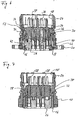
- FIGS. 2 and 3 each show a contact carrier unit 26, which serves as a carrier for an arrangement of electrical contact elements 28 in a conventional manner.
- a contact carrier unit 26 which serves as a carrier for an arrangement of electrical contact elements 28 in a conventional manner.
- the carrier unit 26 is carried out in both cases substantially identical, at least as far as the essential aspects of the invention. Therefore, it is provided in both figures with the same reference numerals, and it is always in the following explanations only generally referred to the contact carrier unit 26, regardless of whether it is equipped with sockets, pins or other form of signal interface elements.
- the contact elements 28 can be connected from the axially rear side with the stripped ends of electrical signal lines.
- the housing 10 is mostly made of metal, the contact carrier unit 26, the intermediate ring 16 and the coding ring 18 are made of plastic, preferably by injection molding. However, it is also a plastic version of the housing 10 is possible.
- the contact carrier unit 26 is designed in two parts. It has an axially front upper part 26a and an axially rear lower part 26b, which are releasably connected to each other by a snap connection.
- the contact elements 28 are embedded in the lower part 26b.
- the intermediate ring 16 is designed on its axially front side with an arrangement of a plurality of circumferentially at equal angular intervals arranged latching tongues 30, which serve the axial support of the intermediate ring 16 on the housing 10.
- the intermediate ring 16 is designed with two such locking tongues 30 which are diametrically opposed to each other. In the presentation of the Fig. 1 only one of the locking tongues 30 can be seen. Instead of two, for example, three or four such locking tongues 30 may be provided.
- the locking tongues 30 protrude from the designated 32 front edge of the intermediate ring 16 axially forward. They represent second locking tongues in the sense of the appended claims.
- the locking tongues 30 have a certain radial flexibility and have at their free ends on a radially outwardly projecting locking projection 34.
- the latching projections 34 snap behind a latching shoulder 36, which is formed on the inner circumferential surface of the housing 10. The engagement of the locking projections 34 with the locking shoulder 36 secures the intermediate ring 16 against removal of the housing in the direction of axially behind. This procedure is good in the Fig. 6 and 9 to recognize.
- the insertion depth of the intermediate ring 16 is limited by the abutment of the front edge 32 of the intermediate ring 16 on an arrangement of in the considered example two diametrically opposite stop projections 38 which are formed on the inner peripheral surface of the housing and protrude radially inward.
- the stopper protrusions 38 prevent the intermediate ring 16 from being pulled forwardly out of the housing 10 Fig. 7 is easy to see how in the installed state of the intermediate ring 16 with its front edge 32 opposite the stop projections 38.
- the stop projections 38 at the same time limit the angle of rotation by which the intermediate ring 16 can be rotated in the installed state relative to the housing 10.
- the intermediate ring 16 carries on its front axial side further an arrangement of a plurality of circumferentially uniformly distributed locking tongues 40 which project axially as the locking tongues 30 from the front edge 32 of the intermediate ring 16 and, for example, have an approximately same axial extent as the locking tongues 30.
- the intermediate ring 16 has an arrangement of a plurality of circumferentially uniformly distributed locking tongues 42 which are exposed by lateral separating slots 44.
- the latching tongues 40, 42 serve to axially support the contact carrier unit 26 in the intermediate ring 16 and constitute first latching tongues in the sense of the appended claims.
- two diametrically opposite latching tongues 40, 42 are provided. Of course, in each case more than two locking tongues 40, 42 may be provided.
- the locking tongues 40 are angularly offset relative to the locking tongues 42, for example, about 40 degrees.
- the intermediate ring 16 is rotatable about this angle relative to the housing 10. A relative rotation by more than this angle is hindered by the stop projections 38.
- the locking tongues 40, 42 have at their free axial ends in each case a radially inwardly projecting latching projection 46.
- the latching projections 46 of the latching tongues 40, 42 respectively engage in a latching recess 48 formed on the contact support unit 26 and thus secure the contact support unit 26 against removal from the intermediate ring 16 in both axial directions
- Fig. 10 enlarged illustrated Section A of Fig. 6 shows the engagement of the latching projection 46 of a latching tongue 42 in a latching recess 48th
- the contact carrier unit 26 On the outer peripheral surface of the contact carrier unit 26 axially extending runways for the locking tongues 40, 42 are formed, namely casseroles 50 for the locking tongues 40 and Auflaufbahnen 52 for the locking tongues 42.
- the casseroles 50, 52 are good in the FIGS. 2 and 3 and also in Fig. 6 to recognize. They are at least partially limited by lateral boundary walls 54, whereby a good guidance of the locking tongues 40, 42 on the casserole webs 50, 52 is achieved.
- the runways 50, 52 have inclined surfaces 56, which cause when inserting the contact carrier unit 26 in the intermediate ring 16, the locking tongues 40 or 42 are deflected radially outward, when they move along the associated raceways 50 and 52 respectively.
- the raceways 50, 52 are the above-mentioned locking recesses 48.
- the locking tongues 40 and 42 and the runways 50 are angularly offset from the runways 52. They are also oriented opposite, ie. the raceways 50 for the locking tongues 40 begin in the region of the axially rear end of the contact carrier unit 26 and terminate in the region of the axially front end of the contact carrier unit 26, the runways 52 for the locking tongues 42, however, run in the reverse direction.
- the above-described embodiment of the contact carrier unit 26 with axially on both sides provided latching tongues 40, 42 and oppositely oriented casserole webs 50, 52 allows the contact carrier unit 26 to be used either from both axial sides in the intermediate ring 16. If the contact carrier unit 26 is inserted axially into the intermediate ring 16 from the front, the latching tongues 40 run onto the bearing tracks 50, while in the opposite case the latching tongues 52 run onto the bearing tracks 52.
- the locking projections 46 of those locking tongues 40 or 42 which are moved up to their associated Auflaufbahnen snap into the corresponding locking recesses 48, are also the locking projections 46 of the other locking tongues 42 and 40 in the associated latching depressions 48. In this way, the contact carrier unit 26 after complete insertion into the intermediate ring 16 secured in both axial directions, regardless of which axial side it was inserted into the intermediate ring 16. This is the locked position of the connector.
- the latching tongues 42 of the intermediate ring 16 engage the lower part 26b of the contact carrier unit 26 and support it axially rearward.
- the latching tongues 40 engage the upper part 26a and support it axially forward. In this way, it is ensured that the lower part 26b is not torn off the upper part 26a when high insertion forces are exerted on the contact elements 28.
- the contact carrier unit 26 on its outer peripheral surface on an axial groove 58.
- the housing 10 has at a peripheral location a radially inwardly projecting nose 60, which in Fig. 1 is recognizable.
- the nose 60 is formed on one of the stop projections 38.
- the nose 60 engages in the axial groove 58 and prevents relative rotation between the housing 10 and contact carrier unit 26.
- the contact carrier unit 26 is secured against rotation by direct engagement with the housing ,
- the contact carrier unit 26 can only then be inserted into the housing 10 when the axial groove 58 of the nose 60 is opposite. As a result, miscarriage of the contact carrier unit 26 is excluded.
- an indexing nose not shown in detail or a Indexierrinne may be formed on the intermediate ring 16, which is associated with a corresponding counter-formation on the housing 10 in order to ensure an angularly correct insertion of the intermediate ring 16 in the housing 10.
- the intermediate ring 16 is rotated relative to the housing 10 and the contact carrier unit 26 by the limited angle of rotation.
- one of the locking tongue assemblies 40 or 42 enters the peripheral region of the raceways of the other locking tongue arrangement.
- the latching tongues 42 pass over the bearing tracks 50.
- the latching projections 46 of the latching tongues 42 lie in this rotated (unlocked) state above the starting region of the runways 50, in particular before their oblique surfaces 56.
- Fig. 11 shows this situation for one of the locking tongues 42.
- the contact carrier unit 26 can be pressed axially out of the intermediate ring 16, when looking at the Fig. 9 downward. If the contact carrier unit 26 is to be inserted again into the intermediate ring 16, this is advantageously initially rotated back by the limited angle of rotation. The contact carrier unit 26 can then be used again, as desired, from one of the two axial sides.
- the locking position and the unlocking position end rotational positions of the rotation angle range, within which the intermediate ring 16 can be rotated.
- Fig. 4 and 8th show the assembled connector - generally indicated at 62 - from the axial front.
- the intermediate ring 16 is moved to the unlocked position while it is in Fig. 4 in the locked position.
- Fig. 12 shows a tool 64 with which the intermediate ring 16 can be rotated between its locking position and its unlocked position.
- the tool 64 is attached to the connector 62 from the axial front. It has a sleeve-shaped end portion 66, in the front-side edge 68 at two diametrically opposite points two recesses or recesses 70 are formed. This leaves two projecting wall portions 72 of the sleeve-shaped end portion 66 stand, which are dimensioned so that they can dive into clearances, which are formed on the axially front side of the intermediate ring 16 between the various locking tongues 30, 40. When turning the tool 64 then the wall portions 72 abut the locking tongues 30, 40, whereby the intermediate ring 16 rotates. The latching tongues 30, 40 thus simultaneously form attack formations of the intermediate ring 16 for the tool 64.
- the tool 64 has a handle portion 74 with a knurled edge 76.
Claims (16)
- Connecteur pour câbles transmettant des signaux, comprenant- un boîtier (10) avec un axe (12) et une cavité (14) s'étendant axialement,- une unité porteuse (26) logeable dans la cavité (14) du boîtier et destinée à porter un système d'éléments d'interface de signalisation (28), lesquels sont déterminés et conçus pour, lorsque le connecteur est connecté à un contre-connecteur, entrer en interaction avec des éléments d'interface de signalisation complémentaires du contre-connecteur pour la transmission des signaux,- une bague intermédiaire séparée (16) insérable dans la cavité (14) du boîtier et destinée au maintien de l'unité porteuse (26), l'unité porteuse (26) et la bague intermédiaire (16) présentant des premiers moyens d'appui axiaux interactifs (40, 42, 46, 48), caractérisés en ce que, à l'état monté, les premiers moyens d'appui axiaux soutiennent l'unité porteuse (26) dans les deux sens axiaux sur la bague intermédiaire (16), et le boîtier (10) et la bague intermédiaire (16) présentant des seconds moyens d'appui axiaux interactifs (30, 32, 34, 36,38), lesquels, à l'état monté, soutiennent l'unité porteuse (26) dans les deux sens axiaux sur le boîtier (10).
- Connecteur selon la revendication 1,
caractérisé en ce que l'unité porteuse (26) comprend une partie supérieure et une partie inférieure pouvant être assemblées dans le sens axial pour former l'unité porteuse, et en ce que le soutien de l'unité porteuse assuré par les premiers moyens d'appui axiaux est, à l'état monté, tel que la partie inférieure est soutenue sur la bague intermédiaire (16) contre un mouvement axial opposé à la partie supérieure et que la partie supérieure est soutenue sur la bague intermédiaire (16) contre un mouvement axial opposé à la partie inférieure. - Connecteur selon la revendication 1 ou 2,
caractérisé en ce que la bague intermédiaire (16) est conçue de telle sorte qu'à l'état monté de la bague intermédiaire (16), il est possible d'insérer l'unité porteuse (26) dans la bague intermédiaire (16). - Connecteur selon l'une des revendications précédentes,
caractérisé en ce que la bague intermédiaire (16) est conçue de telle sorte qu'il est possible d'insérer l'unité porteuse (26) dans la bague intermédiaire (16) à partir des deux côtés axiaux. - Connecteur selon l'une des revendications précédentes,
caractérisé en ce qu'à l'état monté, la bague intermédiaire (16) et l'unité porteuse (26) sont mobiles en rotation l'une par rapport à l'autre, notamment suivant un angle de rotation limité, le connecteur étant déplaçable par rotation relative de la bague intermédiaire (16) par rapport à l'unité porteuse (26) entre un état verrouillé, dans lequel l'unité porteuse (26) est verrouillée axialement par rapport à la bague intermédiaire (16), et un état déverrouillé, dans lequel l'unité porteuse (26) est déverrouillée de la bague intermédiaire (16) dans au moins un sens axial. - Connecteur selon la revendication 5,
caractérisé en ce qu'à l'état monté, l'unité porteuse (26) est fixe en rotation par rapport au boîtier (10), et la bague intermédiaire (16) mobile en rotation par rapport au boîtier. - Connecteur selon la revendication 5 ou 6,
caractérisé en ce que la bague intermédiaire (16) est pourvue de dispositifs d'attaque pour un outil de déverrouillage. - Connecteur selon l'une des revendications précédentes,
caractérisé en ce que la bague intermédiaire (16) présente au moins sur un côté axial un dispositif constitué d'au moins deux premières languettes d'encliquetage déviables radialement (40) et munies de saillies d'encliquetage (46) dirigées radialement vers l'intérieur, et en ce qu'il est formé sur l'unité porteuse (26), pour chaque première languette d'encliquetage (40), une voie d'attaque (50) qui s'étend au moins sectoriellement de manière oblique par rapport au sens axial et se poursuit, à son extrémité, par un renfoncement d'encliquetage (48), chaque première languette d'encliquetage (40) prévue sur ce côté axial de la bague intermédiaire venant, lorsque l'unité porteuse (26) est introduite dans la bague intermédiaire à partir d'un côté axial de cette dernière, s'engager sur l'une des voies d'attaque (50) pour aller finalement s'enclencher dans le renfoncement d'encliquetage correspondant (48). - Connecteur selon la revendication 8,
caractérisé en ce que les voies d'attaque (50) sont, au moins sur une partie de leur longueur axiale, délimitées latéralement par des parois de délimitation (54). - Connecteur selon la revendication 8 ou 9,
caractérisé en ce que la bague intermédiaire (16) présente sur chacun de ses deux côtés axiaux un dispositif constitué d'au moins deux premières languettes d'encliquetage (40, 42) et qu'il est formé sur l'unité porteuse (26) un dispositif de voies d'attaque (50, 52) en association avec chacun des premiers dispositifs de languettes d'encliquetage, que les deux premiers dispositifs de languettes d'encliquetage (40, 42) de la bague intermédiaire (16) sont décalés l'un par rapport l'autre dans le sens circonférentiel, notamment de telle sorte qu'ils ne se chevauchent pas dans le sens circonférentiel, et que les deux dispositifs de voies d'attaque (50, 52) sont pareillement décalés l'un par rapport à l'autre dans le sens circonférentiel. - Connecteur selon la revendication 10,
caractérisé en ce que, à l'état monté, la bague intermédiaire (16) et l'unité porteuse (26) sont mobiles en rotation l'une par rapport à l'autre, notamment suivant un angle de rotation limité, les saillies d'encliquetage (46) d'un (42) des deux premiers dispositifs de languettes d'encliquetage (40, 42) pouvant, par rotation relative de la bague intermédiaire et de l'unité porteuse, se dégager des renfoncements d'encliquetage (48) des voies d'attaque (52) associées à ce premier dispositif de languettes d'encliquetage (42) pour venir dans la zone circonférentielle des voies d'attaque (50) associées à l'autre premier dispositif de languettes d'encliquetage (40). - Connecteur selon l'une des revendications précédentes,
caractérisé en ce que la bague intermédiaire (16) présente un dispositif constitué d'au moins deux secondes languettes d'encliquetage déviables radialement (30) et munies de saillies d'encliquetage (34) dirigées radialement vers l'extérieur, lesquelles lors de l'insertion de la bague intermédiaire (16) dans le boîtier (10) s'enclenchent par encliquetage dans un contre-dispositif de verrouillage attribué (36) du boîtier (10). - Connecteur selon l'une des revendications précédentes,
caractérisé en ce que le boîtier (10) présente une bride de montage (20) servant à fixer le connecteur sur une structure à laquelle il est subordonné. - Connecteur selon l'une des revendications précédentes,
caractérisé en ce que la bague intermédiaire (16) est réalisée en matière synthétique, de préférence moulée par injection. - Outil pour le déverrouillage d'un connecteur selon l'une des revendications 7 à 14,
caractérisé en ce que l'outil présente un segment terminal en forme de douille sur lequel sont formés des contre-dispositifs d'attaque en vue de leur venue en prise avec les dispositifs d'attaque de la bague intermédiaire (16) du connecteur. - Outil selon la revendication 15,
caractérisé en ce qu'au moins un évidement périphérique frontal est ménagé dans le segment terminal en forme de douille de l'outil pour former lesdits contre-dispositifs d'attaque.
Applications Claiming Priority (2)
| Application Number | Priority Date | Filing Date | Title |
|---|---|---|---|
| DE102004018103A DE102004018103B3 (de) | 2004-04-14 | 2004-04-14 | Verbinder für signalübertragende Kabel |
| DE102004018103 | 2004-04-14 |
Publications (2)
| Publication Number | Publication Date |
|---|---|
| EP1587175A1 EP1587175A1 (fr) | 2005-10-19 |
| EP1587175B1 true EP1587175B1 (fr) | 2008-07-16 |
Family
ID=34833252
Family Applications (1)
| Application Number | Title | Priority Date | Filing Date |
|---|---|---|---|
| EP05008073A Active EP1587175B1 (fr) | 2004-04-14 | 2005-04-13 | Connecteur pour cable transmettant des signaux |
Country Status (3)
| Country | Link |
|---|---|
| EP (1) | EP1587175B1 (fr) |
| AT (1) | ATE401680T1 (fr) |
| DE (2) | DE102004018103B3 (fr) |
Families Citing this family (3)
| Publication number | Priority date | Publication date | Assignee | Title |
|---|---|---|---|---|
| DE202009000542U1 (de) * | 2009-01-14 | 2010-06-02 | Coninvers Gmbh | Elektrischer Steckverbinder mit rastbarem werkzeuglos lösbarem Isolierkörper |
| DE202015100245U1 (de) * | 2015-01-21 | 2016-02-02 | FILTEC GmbH Filtertechnologie für die Elektronikindustrie | Steckerbuchsenanordnung umfassend eine abgeschirmte Steckerbuchse für Leiterplatten oder Platinen |
| DE102018124821A1 (de) * | 2018-10-09 | 2020-04-09 | Phoenix Contact E-Mobility Gmbh | Steckverbinderteil mit einem mit einem Gehäuseteil zu verbindenden Inletteil |
Family Cites Families (7)
| Publication number | Priority date | Publication date | Assignee | Title |
|---|---|---|---|---|
| US4361376A (en) * | 1980-11-14 | 1982-11-30 | The Bendix Corporation | Electrical connector |
| DE3700513A1 (de) * | 1987-01-09 | 1988-07-21 | Schaltbau Gmbh | Kontaktanordnung mit einem dosenfoermigen gehaeuse |
| DE8804630U1 (fr) * | 1988-04-08 | 1989-05-11 | Souriau Electric Gmbh, 4006 Erkrath, De | |
| DE4035096A1 (de) * | 1990-05-23 | 1991-11-28 | Amphenol Tuchel Elect | Doppelverrastmechanismus, insbesondere fuer einen rundsteckverbinder |
| NL1002340C2 (nl) * | 1996-02-14 | 1997-08-15 | Ecs Electronics N V | Contactdoos. |
| DE29719217U1 (de) * | 1997-10-30 | 1998-02-19 | Hengstler Peter Gmbh & Co Kg | Mehrpoliger Steckverbinder |
| JP3540156B2 (ja) * | 1998-06-10 | 2004-07-07 | 矢崎総業株式会社 | 防水コネクタ及び該防水コネクタの組付方法 |
-
2004
- 2004-04-14 DE DE102004018103A patent/DE102004018103B3/de not_active Expired - Fee Related
-
2005
- 2005-04-13 AT AT05008073T patent/ATE401680T1/de active
- 2005-04-13 EP EP05008073A patent/EP1587175B1/fr active Active
- 2005-04-13 DE DE502005004693T patent/DE502005004693D1/de active Active
Also Published As
| Publication number | Publication date |
|---|---|
| EP1587175A1 (fr) | 2005-10-19 |
| DE102004018103B3 (de) | 2005-09-08 |
| ATE401680T1 (de) | 2008-08-15 |
| DE502005004693D1 (de) | 2008-08-28 |
Similar Documents
| Publication | Publication Date | Title |
|---|---|---|
| EP2452220B1 (fr) | Dispositif de connexion pour câble optique | |
| EP1275173B1 (fr) | Connecteur comportant une douille | |
| DE2316582A1 (de) | Elektrisches verbindungsstueck | |
| DE102017113875B3 (de) | Elektrischer Stecker mit einem Schutzleiterkontakt und damit einstückig ausgebildeten Schutzleiterverbindungselement zur Erdung von Außenteilen | |
| EP1913661B1 (fr) | Connecteur comprenant un ressort de retenue destine a une borne de mise a la terre | |
| DE102015120921B4 (de) | Steckverbinder und Steckerverbinderanordnung | |
| EP2998485B1 (fr) | Bouton rotatif destine a actionner un adaptateur de cylindre d'un barillet | |
| EP1155475B1 (fr) | Connecteur electrique a fiches | |
| EP0368115A2 (fr) | Comprimé buccal | |
| DE102011002135B4 (de) | Steckerelement mit zweiter Kontaktsicherung | |
| EP3776750B1 (fr) | Pièce de connecteur électrique et système de connexion électrique avec verrouillage | |
| DE19927198B4 (de) | Lampenfassung aus Isolierstoff | |
| EP1587175B1 (fr) | Connecteur pour cable transmettant des signaux | |
| EP3819138B1 (fr) | Unité d'installation | |
| DE69926517T2 (de) | Verbindungsstecker | |
| EP1672751B1 (fr) | Douille de lampe | |
| DE19908469A1 (de) | Buchsenstecker zur Aufnahme eines Koaxialsteckers mit umlaufender Nut | |
| DE10009750B4 (de) | Schutzleiterverbindung | |
| EP1756919B1 (fr) | Adaptateur de branchement electrique et prise de courant | |
| EP0834960B1 (fr) | Prise électrique | |
| EP2998486A1 (fr) | Bouton rotatif destine a actionner un adaptateur de cylindre d'un barillet | |
| DE102019130176B4 (de) | Steckverbinderteil mit einer Rasteinrichtung | |
| EP0388489B1 (fr) | Connecteur électrique | |
| EP0327701A1 (fr) | Prise respectivement fiche pour un dispositif électrique multipolaire de connexion | |
| DE10346367B4 (de) | Freidrehbarer HF-Winkelsteckverbinder |
Legal Events
| Date | Code | Title | Description |
|---|---|---|---|
| PUAI | Public reference made under article 153(3) epc to a published international application that has entered the european phase |
Free format text: ORIGINAL CODE: 0009012 |
|
| AK | Designated contracting states |
Kind code of ref document: A1 Designated state(s): AT BE BG CH CY CZ DE DK EE ES FI FR GB GR HU IE IS IT LI LT LU MC NL PL PT RO SE SI SK TR |
|
| AX | Request for extension of the european patent |
Extension state: AL BA HR LV MK YU |
|
| 17P | Request for examination filed |
Effective date: 20051025 |
|
| AKX | Designation fees paid |
Designated state(s): AT BE BG CH CY CZ DE DK EE ES FI FR GB GR HU IE IS IT LI LT LU MC NL PL PT RO SE SI SK TR |
|
| GRAP | Despatch of communication of intention to grant a patent |
Free format text: ORIGINAL CODE: EPIDOSNIGR1 |
|
| GRAS | Grant fee paid |
Free format text: ORIGINAL CODE: EPIDOSNIGR3 |
|
| GRAA | (expected) grant |
Free format text: ORIGINAL CODE: 0009210 |
|
| AK | Designated contracting states |
Kind code of ref document: B1 Designated state(s): AT BE BG CH CY CZ DE DK EE ES FI FR GB GR HU IE IS IT LI LT LU MC NL PL PT RO SE SI SK TR |
|
| REG | Reference to a national code |
Ref country code: GB Ref legal event code: FG4D Free format text: NOT ENGLISH |
|
| REG | Reference to a national code |
Ref country code: CH Ref legal event code: EP |
|
| REF | Corresponds to: |
Ref document number: 502005004693 Country of ref document: DE Date of ref document: 20080828 Kind code of ref document: P |
|
| REG | Reference to a national code |
Ref country code: IE Ref legal event code: FG4D Free format text: LANGUAGE OF EP DOCUMENT: GERMAN |
|
| NLV1 | Nl: lapsed or annulled due to failure to fulfill the requirements of art. 29p and 29m of the patents act | ||
| PG25 | Lapsed in a contracting state [announced via postgrant information from national office to epo] |
Ref country code: NL Free format text: LAPSE BECAUSE OF FAILURE TO SUBMIT A TRANSLATION OF THE DESCRIPTION OR TO PAY THE FEE WITHIN THE PRESCRIBED TIME-LIMIT Effective date: 20080716 Ref country code: LT Free format text: LAPSE BECAUSE OF FAILURE TO SUBMIT A TRANSLATION OF THE DESCRIPTION OR TO PAY THE FEE WITHIN THE PRESCRIBED TIME-LIMIT Effective date: 20080716 Ref country code: ES Free format text: LAPSE BECAUSE OF FAILURE TO SUBMIT A TRANSLATION OF THE DESCRIPTION OR TO PAY THE FEE WITHIN THE PRESCRIBED TIME-LIMIT Effective date: 20081027 Ref country code: PT Free format text: LAPSE BECAUSE OF FAILURE TO SUBMIT A TRANSLATION OF THE DESCRIPTION OR TO PAY THE FEE WITHIN THE PRESCRIBED TIME-LIMIT Effective date: 20081216 Ref country code: IS Free format text: LAPSE BECAUSE OF FAILURE TO SUBMIT A TRANSLATION OF THE DESCRIPTION OR TO PAY THE FEE WITHIN THE PRESCRIBED TIME-LIMIT Effective date: 20081116 |
|
| PG25 | Lapsed in a contracting state [announced via postgrant information from national office to epo] |
Ref country code: FI Free format text: LAPSE BECAUSE OF FAILURE TO SUBMIT A TRANSLATION OF THE DESCRIPTION OR TO PAY THE FEE WITHIN THE PRESCRIBED TIME-LIMIT Effective date: 20080716 Ref country code: SI Free format text: LAPSE BECAUSE OF FAILURE TO SUBMIT A TRANSLATION OF THE DESCRIPTION OR TO PAY THE FEE WITHIN THE PRESCRIBED TIME-LIMIT Effective date: 20080716 Ref country code: BG Free format text: LAPSE BECAUSE OF FAILURE TO SUBMIT A TRANSLATION OF THE DESCRIPTION OR TO PAY THE FEE WITHIN THE PRESCRIBED TIME-LIMIT Effective date: 20081016 |
|
| REG | Reference to a national code |
Ref country code: IE Ref legal event code: FD4D |
|
| PG25 | Lapsed in a contracting state [announced via postgrant information from national office to epo] |
Ref country code: EE Free format text: LAPSE BECAUSE OF FAILURE TO SUBMIT A TRANSLATION OF THE DESCRIPTION OR TO PAY THE FEE WITHIN THE PRESCRIBED TIME-LIMIT Effective date: 20080716 Ref country code: IE Free format text: LAPSE BECAUSE OF FAILURE TO SUBMIT A TRANSLATION OF THE DESCRIPTION OR TO PAY THE FEE WITHIN THE PRESCRIBED TIME-LIMIT Effective date: 20080716 Ref country code: DK Free format text: LAPSE BECAUSE OF FAILURE TO SUBMIT A TRANSLATION OF THE DESCRIPTION OR TO PAY THE FEE WITHIN THE PRESCRIBED TIME-LIMIT Effective date: 20080716 |
|
| PLBE | No opposition filed within time limit |
Free format text: ORIGINAL CODE: 0009261 |
|
| STAA | Information on the status of an ep patent application or granted ep patent |
Free format text: STATUS: NO OPPOSITION FILED WITHIN TIME LIMIT |
|
| PG25 | Lapsed in a contracting state [announced via postgrant information from national office to epo] |
Ref country code: RO Free format text: LAPSE BECAUSE OF FAILURE TO SUBMIT A TRANSLATION OF THE DESCRIPTION OR TO PAY THE FEE WITHIN THE PRESCRIBED TIME-LIMIT Effective date: 20080716 Ref country code: SK Free format text: LAPSE BECAUSE OF FAILURE TO SUBMIT A TRANSLATION OF THE DESCRIPTION OR TO PAY THE FEE WITHIN THE PRESCRIBED TIME-LIMIT Effective date: 20080716 Ref country code: CZ Free format text: LAPSE BECAUSE OF FAILURE TO SUBMIT A TRANSLATION OF THE DESCRIPTION OR TO PAY THE FEE WITHIN THE PRESCRIBED TIME-LIMIT Effective date: 20080716 |
|
| 26N | No opposition filed |
Effective date: 20090417 |
|
| PG25 | Lapsed in a contracting state [announced via postgrant information from national office to epo] |
Ref country code: IT Free format text: LAPSE BECAUSE OF FAILURE TO SUBMIT A TRANSLATION OF THE DESCRIPTION OR TO PAY THE FEE WITHIN THE PRESCRIBED TIME-LIMIT Effective date: 20080716 |
|
| BERE | Be: lapsed |
Owner name: U.I. LAPP G.M.B.H. Effective date: 20090430 |
|
| GBPC | Gb: european patent ceased through non-payment of renewal fee |
Effective date: 20090413 |
|
| REG | Reference to a national code |
Ref country code: FR Ref legal event code: ST Effective date: 20091231 |
|
| PG25 | Lapsed in a contracting state [announced via postgrant information from national office to epo] |
Ref country code: SE Free format text: LAPSE BECAUSE OF FAILURE TO SUBMIT A TRANSLATION OF THE DESCRIPTION OR TO PAY THE FEE WITHIN THE PRESCRIBED TIME-LIMIT Effective date: 20081016 |
|
| PG25 | Lapsed in a contracting state [announced via postgrant information from national office to epo] |
Ref country code: MC Free format text: LAPSE BECAUSE OF NON-PAYMENT OF DUE FEES Effective date: 20090430 Ref country code: FR Free format text: LAPSE BECAUSE OF NON-PAYMENT OF DUE FEES Effective date: 20091222 Ref country code: GB Free format text: LAPSE BECAUSE OF NON-PAYMENT OF DUE FEES Effective date: 20090413 |
|
| PG25 | Lapsed in a contracting state [announced via postgrant information from national office to epo] |
Ref country code: PL Free format text: LAPSE BECAUSE OF FAILURE TO SUBMIT A TRANSLATION OF THE DESCRIPTION OR TO PAY THE FEE WITHIN THE PRESCRIBED TIME-LIMIT Effective date: 20080716 Ref country code: BE Free format text: LAPSE BECAUSE OF NON-PAYMENT OF DUE FEES Effective date: 20090430 |
|
| PG25 | Lapsed in a contracting state [announced via postgrant information from national office to epo] |
Ref country code: GR Free format text: LAPSE BECAUSE OF FAILURE TO SUBMIT A TRANSLATION OF THE DESCRIPTION OR TO PAY THE FEE WITHIN THE PRESCRIBED TIME-LIMIT Effective date: 20081017 |
|
| PG25 | Lapsed in a contracting state [announced via postgrant information from national office to epo] |
Ref country code: LU Free format text: LAPSE BECAUSE OF NON-PAYMENT OF DUE FEES Effective date: 20090413 |
|
| PG25 | Lapsed in a contracting state [announced via postgrant information from national office to epo] |
Ref country code: HU Free format text: LAPSE BECAUSE OF FAILURE TO SUBMIT A TRANSLATION OF THE DESCRIPTION OR TO PAY THE FEE WITHIN THE PRESCRIBED TIME-LIMIT Effective date: 20090117 |
|
| PG25 | Lapsed in a contracting state [announced via postgrant information from national office to epo] |
Ref country code: TR Free format text: LAPSE BECAUSE OF FAILURE TO SUBMIT A TRANSLATION OF THE DESCRIPTION OR TO PAY THE FEE WITHIN THE PRESCRIBED TIME-LIMIT Effective date: 20080716 |
|
| PG25 | Lapsed in a contracting state [announced via postgrant information from national office to epo] |
Ref country code: CY Free format text: LAPSE BECAUSE OF FAILURE TO SUBMIT A TRANSLATION OF THE DESCRIPTION OR TO PAY THE FEE WITHIN THE PRESCRIBED TIME-LIMIT Effective date: 20080716 |
|
| PGFP | Annual fee paid to national office [announced via postgrant information from national office to epo] |
Ref country code: CH Payment date: 20140418 Year of fee payment: 10 Ref country code: AT Payment date: 20140411 Year of fee payment: 10 |
|
| REG | Reference to a national code |
Ref country code: CH Ref legal event code: PL |
|
| REG | Reference to a national code |
Ref country code: AT Ref legal event code: MM01 Ref document number: 401680 Country of ref document: AT Kind code of ref document: T Effective date: 20150413 |
|
| PG25 | Lapsed in a contracting state [announced via postgrant information from national office to epo] |
Ref country code: LI Free format text: LAPSE BECAUSE OF NON-PAYMENT OF DUE FEES Effective date: 20150430 Ref country code: CH Free format text: LAPSE BECAUSE OF NON-PAYMENT OF DUE FEES Effective date: 20150430 |
|
| PG25 | Lapsed in a contracting state [announced via postgrant information from national office to epo] |
Ref country code: AT Free format text: LAPSE BECAUSE OF NON-PAYMENT OF DUE FEES Effective date: 20150413 |
|
| PGFP | Annual fee paid to national office [announced via postgrant information from national office to epo] |
Ref country code: DE Payment date: 20230420 Year of fee payment: 19 |