EP1587175B1 - Connector for signaltransmitting cable - Google Patents
Connector for signaltransmitting cable Download PDFInfo
- Publication number
- EP1587175B1 EP1587175B1 EP05008073A EP05008073A EP1587175B1 EP 1587175 B1 EP1587175 B1 EP 1587175B1 EP 05008073 A EP05008073 A EP 05008073A EP 05008073 A EP05008073 A EP 05008073A EP 1587175 B1 EP1587175 B1 EP 1587175B1
- Authority
- EP
- European Patent Office
- Prior art keywords
- intermediate ring
- carrier unit
- housing
- connector
- axial
- Prior art date
- Legal status (The legal status is an assumption and is not a legal conclusion. Google has not performed a legal analysis and makes no representation as to the accuracy of the status listed.)
- Active
Links
Images


Classifications
-
- H—ELECTRICITY
- H01—ELECTRIC ELEMENTS
- H01R—ELECTRICALLY-CONDUCTIVE CONNECTIONS; STRUCTURAL ASSOCIATIONS OF A PLURALITY OF MUTUALLY-INSULATED ELECTRICAL CONNECTING ELEMENTS; COUPLING DEVICES; CURRENT COLLECTORS
- H01R13/00—Details of coupling devices of the kinds covered by groups H01R12/70 or H01R24/00 - H01R33/00
- H01R13/46—Bases; Cases
- H01R13/502—Bases; Cases composed of different pieces
- H01R13/506—Bases; Cases composed of different pieces assembled by snap action of the parts
-
- H—ELECTRICITY
- H01—ELECTRIC ELEMENTS
- H01R—ELECTRICALLY-CONDUCTIVE CONNECTIONS; STRUCTURAL ASSOCIATIONS OF A PLURALITY OF MUTUALLY-INSULATED ELECTRICAL CONNECTING ELEMENTS; COUPLING DEVICES; CURRENT COLLECTORS
- H01R43/00—Apparatus or processes specially adapted for manufacturing, assembling, maintaining, or repairing of line connectors or current collectors or for joining electric conductors
- H01R43/20—Apparatus or processes specially adapted for manufacturing, assembling, maintaining, or repairing of line connectors or current collectors or for joining electric conductors for assembling or disassembling contact members with insulating base, case or sleeve
- H01R43/22—Hand tools
Definitions
- the invention relates to a connector for signal transmitting cables, comprising a housing having an axis and an axially extending cavity and a housing unit accommodated in the carrier unit for an array of signal interface elements, which are intended and designed, when connecting the connector with a mating connector in signal transmitting Interact with complementary signal interface elements of the mating connector.
- signal interface elements those components of the connector are understood here, at which the signals to be transmitted via the connector can be tapped off and / or fed in.
- the signal interface elements are electrical contact elements, for example in the form of contact sockets or contact pins.
- the signal interface elements are optical coupling elements into which light signals from a mating connector can be fed and / or from which light signals directed to the connector can be output.
- the carrier unit is inserted from an axially rear end of the connector housing forth in the housing cavity, and indeed so far, until it abuts against a housing-side stop collar. At this stop collar, the carrier unit is supported in the direction of the front axially. After axially behind the support of the carrier unit is taken over by a snap ring which is received in a circumferential groove of the carrier unit. To insert the carrier unit, the snap ring must be compressed in order to be able to move past a housing-side shoulder. After passing over the shoulder, the snap ring relaxes radially outward and prevents by interacting with the shoulder that the carrier unit can be pushed out of the housing to the rear.
- the carrier unit is made in two parts with an axially front upper part and an axially rear lower part.
- the upper part and the lower part are held together by a snap connection.
- the electrical contact elements are embedded in the lower part.
- the snap ring is inserted into a groove on the upper part. This is the part that precedes when inserting the carrier unit in the housing and abuts the stop collar of the housing.
- DE 40 35 096 C2 shows an example of an electrical connector with a two-part insulating contact carrier unit.
- the contact carrier unit is composed of an upper part and a lower part, which are held together by a latching connection.
- the lower part of the contact carrier unit is designed with latching tongues, which serve for latching the contact carrier unit to a housing sleeve of the plug connector.
- This document also shows an unlocking tool for unlocking the contact carrier unit.
- a connector with a one-piece insulating support for one or more electrical contact elements is known, which is held in a connector housing by means of a securing ring.
- the insulating support is inserted into the connector housing in an axial direction and limited in movement by cooperative axial stops of the insulating support and the connector housing in the insertion direction.
- the retaining ring secures the insulating support against falling out of the connector housing against the insertion direction.
- DE 297 19 217 U1 discloses an electrical connector with a support unit for electrical contact pins or sockets, wherein the carrier unit comprises a receiving body, in the outer circumferential surface of which a plurality of receiving grooves for receiving the contact pins or sockets are formed.
- the receiving body is inserted on a part of its axial length in a carrier sleeve made of electrically insulating material and enclosed on the remainder of its axial length by a slotted insulating sleeve which can be coupled to the carrier sleeve.
- the contact support unit thus formed is held axially between two radial shoulders of a housing of the connector.
- the housing has two housing parts which can be screwed together and which each support one of the radial shoulders.
- US 4,361,376 further shows an integrally manufactured contact carrier for electrical contact elements of a connector.
- the contact carrier carries on its outer circumference two rows of integrally molded fingers, one of which is flexibly deflectable in the radial direction and the other of which are flexibly deflectable in the axial direction of the connector.
- the fingers engage in an inner circumferential groove of the housing.
- the contact carrier is supported by its axial deflectable fingers on an axial boundary shoulder of the groove and with its radially deflectable fingers on an opposite axial boundary shoulder of the groove.
- the axially deflectable fingers a wobble-free fit of the contact carrier is achieved in the housing.
- EP 0 795 439 A1 discloses a to be mounted on a substrate outlet, the substrate is in particular a located at the rear of a vehicle component, such as a connected to a trailer hitch or a bumper.
- the socket has a housing attachable to the base, in which an annular support member via a contact carrier is held. The support member is supported in an axial direction directly on the ground.
- connector of the type described in an insertable into the housing cavity separate intermediate ring for supporting the carrier unit is provided, wherein the carrier unit and the intermediate ring cooperating first Axialstweilstoff which support the carrier unit in both axial directions on the intermediate ring in the installed state, and wherein the housing and the intermediate ring have cooperating second Axialstweilstoff, which support the intermediate ring in the installed state in both axial directions on the housing.
- the inventive construction allows a high freedom of design to achieve an optimized support of the carrier unit in the housing cavity.
- the supported by the first axial support means support of the support unit may then be in the installed state such that the lower part is supported on the intermediate ring against axial movement away from the upper part and the upper part is supported on the intermediate ring against axial movement away from the lower part.
- the risk that the upper part and the lower part are torn apart when joining the connector with a mating connector can be avoided.
- the intermediate ring is designed such that in the installed state of the intermediate ring insertion of the carrier unit is made possible in the intermediate ring. It can then be installed in the housing in advance of the intermediate ring.
- the carrier unit optionally with a cable connected thereto, can be conveniently inserted into the semi-assembled connector at a later date.
- the intermediate ring is preferably designed such that an insertion of the carrier unit in the intermediate ring is made possible from both axial sides.
- This is particularly advantageous in connection with connectors which are provided for fixed installation in a superordinate construction and for this purpose have a fastening flange on their housing.
- a connector may be attached to a housing wall of an electrical or electronic device.
- the carrier unit can be optionally installed either from the front or from behind in the housing of the connector.
- the connector is adjustable by relative rotation of the intermediate ring relative to the support unit between a locked state in which the support unit is axially locked against the intermediate ring, and an unlocked state in which the support unit is unlocked in at least one axial direction of the intermediate ring.
- the support unit may be rotationally fixed in the installed state relative to the housing, while the intermediate ring is rotatable relative to the housing. Since it may be troublesome to unlock the connector with bare hands, it is expedient if the intermediate ring is designed with attack information for an unlocking tool.
- the intermediate ring has at least on one axial side an arrangement of at least two first radially deflectable latching tongues with radially inwardly directed latching projections.
- an at least partially oblique runway extending obliquely to the axial is formed for each first latching tongue, which merges at its end into a latching recess.
- the runways can be limited laterally by boundary walls at least over part of their axial length.
- the intermediate ring can each have an arrangement of at least two first snap-in tongues on its two axial sides, wherein an arrangement of run-on tracks is formed on the carrier unit in association with each of the first latching tongue arrangements.
- the two first locking tongue arrangements of the intermediate ring are offset from each other in the angular direction. Accordingly, the two arrangements of raceways are angularly offset from one another.
- the intermediate ring and the support unit are rotatable relative to each other at least by an angle corresponding to the angular offset between the two first latching tongue assemblies, wherein by relative rotation of the intermediate ring and the carrier unit, the latching projections of one of the two first latching tongue arrangements of the engagement with the locking recesses of this the first latching tongue arrangement assigned runways are movable in the peripheral region of those runways, which are associated with the other first latching tongue arrangement.
- the mutual locking of the carrier unit and the intermediate ring can be solved in a simple manner by relative rotation of these two components.
- the intermediate ring can have an arrangement of at least two second radially deflectable latching tongues with radially outwardly directed latching projections, which snap into place when the intermediate ring is inserted into the housing into an associated latching counter-formation of the housing.
- the invention also relates to a tool for unlocking a connector with an intermediate ring rotatable between a locking rotational position and an unlocking rotational position.
- the tool has a sleeve-shaped end portion on which counter attack formations are formed for engagement with engagement formations of the intermediate ring of the connector.
- To form the counter-attack formations preferably at least one end-side edge recess is formed in the sleeve-shaped end section of the tool.
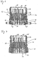
- components of a circular connector include a connector housing 10 having a housing longitudinal axis 12 and an axially extending housing cavity 14, also an intermediate or retaining ring 16 and a coding ring 18.
- the housing 10 has in the region of one of its axial ends (hereinafter referred to as the rear end) a mounting flange 20, by means of which the connector can be fastened, for example, to a housing wall of an electrical device carrying a plurality of such connectors.
- the mounting flange 20 has for this purpose mounting holes 22 for receiving fastening screws, not shown.
- the housing 10 is formed substantially sleeve-shaped.
- the coding ring 18 serves to code the connector and is inserted into an axially front end portion 24 of the housing 10 from the front.
- the intermediate ring 16 serves to hold a contact carrier unit, of the two variants in the FIGS. 2 and 3 are shown. It is inserted from the axially rear side into the housing 10 and is supported in the installed state both after axially forward and axially behind the housing 10. In the installed state, the intermediate ring 16 is rotatable about the axis 12 by a limited angle of rotation relative to the housing. By rotation about this limited angle of rotation of the intermediate ring 16 can be adjusted in the installed state between a locked and an unlocked position.
- FIGS. 2 and 3 each show a contact carrier unit 26, which serves as a carrier for an arrangement of electrical contact elements 28 in a conventional manner.
- a contact carrier unit 26 which serves as a carrier for an arrangement of electrical contact elements 28 in a conventional manner.
- the carrier unit 26 is carried out in both cases substantially identical, at least as far as the essential aspects of the invention. Therefore, it is provided in both figures with the same reference numerals, and it is always in the following explanations only generally referred to the contact carrier unit 26, regardless of whether it is equipped with sockets, pins or other form of signal interface elements.
- the contact elements 28 can be connected from the axially rear side with the stripped ends of electrical signal lines.
- the housing 10 is mostly made of metal, the contact carrier unit 26, the intermediate ring 16 and the coding ring 18 are made of plastic, preferably by injection molding. However, it is also a plastic version of the housing 10 is possible.
- the contact carrier unit 26 is designed in two parts. It has an axially front upper part 26a and an axially rear lower part 26b, which are releasably connected to each other by a snap connection.
- the contact elements 28 are embedded in the lower part 26b.
- the intermediate ring 16 is designed on its axially front side with an arrangement of a plurality of circumferentially at equal angular intervals arranged latching tongues 30, which serve the axial support of the intermediate ring 16 on the housing 10.
- the intermediate ring 16 is designed with two such locking tongues 30 which are diametrically opposed to each other. In the presentation of the Fig. 1 only one of the locking tongues 30 can be seen. Instead of two, for example, three or four such locking tongues 30 may be provided.
- the locking tongues 30 protrude from the designated 32 front edge of the intermediate ring 16 axially forward. They represent second locking tongues in the sense of the appended claims.
- the locking tongues 30 have a certain radial flexibility and have at their free ends on a radially outwardly projecting locking projection 34.
- the latching projections 34 snap behind a latching shoulder 36, which is formed on the inner circumferential surface of the housing 10. The engagement of the locking projections 34 with the locking shoulder 36 secures the intermediate ring 16 against removal of the housing in the direction of axially behind. This procedure is good in the Fig. 6 and 9 to recognize.
- the insertion depth of the intermediate ring 16 is limited by the abutment of the front edge 32 of the intermediate ring 16 on an arrangement of in the considered example two diametrically opposite stop projections 38 which are formed on the inner peripheral surface of the housing and protrude radially inward.
- the stopper protrusions 38 prevent the intermediate ring 16 from being pulled forwardly out of the housing 10 Fig. 7 is easy to see how in the installed state of the intermediate ring 16 with its front edge 32 opposite the stop projections 38.
- the stop projections 38 at the same time limit the angle of rotation by which the intermediate ring 16 can be rotated in the installed state relative to the housing 10.
- the intermediate ring 16 carries on its front axial side further an arrangement of a plurality of circumferentially uniformly distributed locking tongues 40 which project axially as the locking tongues 30 from the front edge 32 of the intermediate ring 16 and, for example, have an approximately same axial extent as the locking tongues 30.
- the intermediate ring 16 has an arrangement of a plurality of circumferentially uniformly distributed locking tongues 42 which are exposed by lateral separating slots 44.
- the latching tongues 40, 42 serve to axially support the contact carrier unit 26 in the intermediate ring 16 and constitute first latching tongues in the sense of the appended claims.
- two diametrically opposite latching tongues 40, 42 are provided. Of course, in each case more than two locking tongues 40, 42 may be provided.
- the locking tongues 40 are angularly offset relative to the locking tongues 42, for example, about 40 degrees.
- the intermediate ring 16 is rotatable about this angle relative to the housing 10. A relative rotation by more than this angle is hindered by the stop projections 38.
- the locking tongues 40, 42 have at their free axial ends in each case a radially inwardly projecting latching projection 46.
- the latching projections 46 of the latching tongues 40, 42 respectively engage in a latching recess 48 formed on the contact support unit 26 and thus secure the contact support unit 26 against removal from the intermediate ring 16 in both axial directions
- Fig. 10 enlarged illustrated Section A of Fig. 6 shows the engagement of the latching projection 46 of a latching tongue 42 in a latching recess 48th
- the contact carrier unit 26 On the outer peripheral surface of the contact carrier unit 26 axially extending runways for the locking tongues 40, 42 are formed, namely casseroles 50 for the locking tongues 40 and Auflaufbahnen 52 for the locking tongues 42.
- the casseroles 50, 52 are good in the FIGS. 2 and 3 and also in Fig. 6 to recognize. They are at least partially limited by lateral boundary walls 54, whereby a good guidance of the locking tongues 40, 42 on the casserole webs 50, 52 is achieved.
- the runways 50, 52 have inclined surfaces 56, which cause when inserting the contact carrier unit 26 in the intermediate ring 16, the locking tongues 40 or 42 are deflected radially outward, when they move along the associated raceways 50 and 52 respectively.
- the raceways 50, 52 are the above-mentioned locking recesses 48.
- the locking tongues 40 and 42 and the runways 50 are angularly offset from the runways 52. They are also oriented opposite, ie. the raceways 50 for the locking tongues 40 begin in the region of the axially rear end of the contact carrier unit 26 and terminate in the region of the axially front end of the contact carrier unit 26, the runways 52 for the locking tongues 42, however, run in the reverse direction.
- the above-described embodiment of the contact carrier unit 26 with axially on both sides provided latching tongues 40, 42 and oppositely oriented casserole webs 50, 52 allows the contact carrier unit 26 to be used either from both axial sides in the intermediate ring 16. If the contact carrier unit 26 is inserted axially into the intermediate ring 16 from the front, the latching tongues 40 run onto the bearing tracks 50, while in the opposite case the latching tongues 52 run onto the bearing tracks 52.
- the locking projections 46 of those locking tongues 40 or 42 which are moved up to their associated Auflaufbahnen snap into the corresponding locking recesses 48, are also the locking projections 46 of the other locking tongues 42 and 40 in the associated latching depressions 48. In this way, the contact carrier unit 26 after complete insertion into the intermediate ring 16 secured in both axial directions, regardless of which axial side it was inserted into the intermediate ring 16. This is the locked position of the connector.
- the latching tongues 42 of the intermediate ring 16 engage the lower part 26b of the contact carrier unit 26 and support it axially rearward.
- the latching tongues 40 engage the upper part 26a and support it axially forward. In this way, it is ensured that the lower part 26b is not torn off the upper part 26a when high insertion forces are exerted on the contact elements 28.
- the contact carrier unit 26 on its outer peripheral surface on an axial groove 58.
- the housing 10 has at a peripheral location a radially inwardly projecting nose 60, which in Fig. 1 is recognizable.
- the nose 60 is formed on one of the stop projections 38.
- the nose 60 engages in the axial groove 58 and prevents relative rotation between the housing 10 and contact carrier unit 26.
- the contact carrier unit 26 is secured against rotation by direct engagement with the housing ,
- the contact carrier unit 26 can only then be inserted into the housing 10 when the axial groove 58 of the nose 60 is opposite. As a result, miscarriage of the contact carrier unit 26 is excluded.
- an indexing nose not shown in detail or a Indexierrinne may be formed on the intermediate ring 16, which is associated with a corresponding counter-formation on the housing 10 in order to ensure an angularly correct insertion of the intermediate ring 16 in the housing 10.
- the intermediate ring 16 is rotated relative to the housing 10 and the contact carrier unit 26 by the limited angle of rotation.
- one of the locking tongue assemblies 40 or 42 enters the peripheral region of the raceways of the other locking tongue arrangement.
- the latching tongues 42 pass over the bearing tracks 50.
- the latching projections 46 of the latching tongues 42 lie in this rotated (unlocked) state above the starting region of the runways 50, in particular before their oblique surfaces 56.
- Fig. 11 shows this situation for one of the locking tongues 42.
- the contact carrier unit 26 can be pressed axially out of the intermediate ring 16, when looking at the Fig. 9 downward. If the contact carrier unit 26 is to be inserted again into the intermediate ring 16, this is advantageously initially rotated back by the limited angle of rotation. The contact carrier unit 26 can then be used again, as desired, from one of the two axial sides.
- the locking position and the unlocking position end rotational positions of the rotation angle range, within which the intermediate ring 16 can be rotated.
- Fig. 4 and 8th show the assembled connector - generally indicated at 62 - from the axial front.
- the intermediate ring 16 is moved to the unlocked position while it is in Fig. 4 in the locked position.
- Fig. 12 shows a tool 64 with which the intermediate ring 16 can be rotated between its locking position and its unlocked position.
- the tool 64 is attached to the connector 62 from the axial front. It has a sleeve-shaped end portion 66, in the front-side edge 68 at two diametrically opposite points two recesses or recesses 70 are formed. This leaves two projecting wall portions 72 of the sleeve-shaped end portion 66 stand, which are dimensioned so that they can dive into clearances, which are formed on the axially front side of the intermediate ring 16 between the various locking tongues 30, 40. When turning the tool 64 then the wall portions 72 abut the locking tongues 30, 40, whereby the intermediate ring 16 rotates. The latching tongues 30, 40 thus simultaneously form attack formations of the intermediate ring 16 for the tool 64.
- the tool 64 has a handle portion 74 with a knurled edge 76.
Abstract
Description
Die Erfindung betrifft einen Verbinder für signalübertragende Kabel, umfassend ein Gehäuse mit einer Achse und einem sich axial erstreckenden Hohlraum sowie eine in dem Gehäusehohlraum aufnehmbare Trägereinheit für eine Anordnung von Signalschnittstellenelementen, welche dazu bestimmt und ausgebildet sind, bei Verbindung des Verbinders mit einem Gegenverbinder in signalübertragende Wechselwirkung mit komplementären Signalschnittstellenelementen des Gegenverbinders zu treten.The invention relates to a connector for signal transmitting cables, comprising a housing having an axis and an axially extending cavity and a housing unit accommodated in the carrier unit for an array of signal interface elements, which are intended and designed, when connecting the connector with a mating connector in signal transmitting Interact with complementary signal interface elements of the mating connector.
Als Signalschnittstellenelemente werden hier diejenigen Komponenten des Verbinders verstanden, an denen die über den Verbinder zu übertragenden Signale abgreifbar oder/und einspeisbar sind. Ist der Verbinder ein elektrischer Verbinder, so handelt es sich bei den Signalschnittstellenelementen um elektrische Kontaktelemente beispielsweise in Form von Kontaktbuchsen oder Kontaktstiften. Im Fall eines optischen Verbinders sind die Signalschnittstellenelemente optische Koppelelemente, in die Lichtsignale von einem Gegenverbinder eingespeist werden können oder/und von denen zu dem Verbinder hingeleitete Lichtsignale ausgegeben werden können.As signal interface elements, those components of the connector are understood here, at which the signals to be transmitted via the connector can be tapped off and / or fed in. If the connector is an electrical connector, the signal interface elements are electrical contact elements, for example in the form of contact sockets or contact pins. In the case of an optical connector, the signal interface elements are optical coupling elements into which light signals from a mating connector can be fed and / or from which light signals directed to the connector can be output.
Bei einer bekannten Lösung eines gattungsgemäßen elektrischen Steckverbinders ist zur Montage des Verbinders die Trägereinheit von einem axial hinteren Ende des Verbindergehäuses her in den Gehäusehohlraum einzuschieben, und zwar so weit, bis sie an einem gehäuseseitigen Anschlagbund anstößt. An diesem Anschlagbund stützt sich die Trägereinheit in Richtung nach axial vorne ab. Nach axial hinten wird die Abstützung der Trägereinheit von einem Sprengring übernommen, der in einer Umfangsnut der Trägereinheit aufgenommen ist. Zum Einsetzen der Trägereinheit muss der Sprengring zusammengedrückt werden, um ihn an einer gehäuseseitigen Schulter vorbeibewegen zu können. Nach Überfahren der Schulter entspannt sich der Sprengring nach radial außen und verhindert durch Zusammenwirken mit der Schulter, dass die Trägereinheit nach hinten aus dem Gehäuse herausgedrückt werden kann.In a known solution of a generic electrical connector for mounting the connector, the carrier unit is inserted from an axially rear end of the connector housing forth in the housing cavity, and indeed so far, until it abuts against a housing-side stop collar. At this stop collar, the carrier unit is supported in the direction of the front axially. After axially behind the support of the carrier unit is taken over by a snap ring which is received in a circumferential groove of the carrier unit. To insert the carrier unit, the snap ring must be compressed in order to be able to move past a housing-side shoulder. After passing over the shoulder, the snap ring relaxes radially outward and prevents by interacting with the shoulder that the carrier unit can be pushed out of the housing to the rear.
Bei der bekannten Lösung ist die Trägereinheit zweiteilig mit einem axial vorderen Oberteil und einem axial hinteren Unterteil ausgeführt. Das Oberteil und das Unterteil werden durch eine Schnappverbindung zusammengehalten. Die elektrischen Kontaktelemente sind in das Unterteil eingebettet. Der Sprengring ist in eine Nut an dem Oberteil eingesetzt. Dieses ist dasjenige Teil, das beim Einführen der Trägereinheit in das Gehäuse vorausläuft und an dem Anschlagbund des Gehäuses anstößt. Beim Zusammenstecken des Steckverbinders mit einem Gegenverbinder besteht dann die Gefahr, dass sich das Unterteil von dem Oberteil losreißt, wenn die auf die Trägereinheit einwirkenden Steckkräfte die Haltekraft der Schnappverbindung zwischen Ober- und Unterteil übersteigen.In the known solution, the carrier unit is made in two parts with an axially front upper part and an axially rear lower part. The upper part and the lower part are held together by a snap connection. The electrical contact elements are embedded in the lower part. The snap ring is inserted into a groove on the upper part. This is the part that precedes when inserting the carrier unit in the housing and abuts the stop collar of the housing. When plugging the connector with a Mating connector then there is a risk that the lower part of the upper part breaks loose when the forces acting on the carrier unit insertion forces exceed the holding force of the snap connection between the upper and lower part.
Aus
Bei einem erfindungsgemäß weitergebildeten Verbinder der eingangs bezeichneten Art ist ein in den Gehäusehohlraum einsetzbarer gesonderter Zwischenring zur Halterung der Trägereinheit vorgesehen, wobei die Trägereinheit und der Zwischenring zusammenwirkende erste Axialstützmittel aufweisen, welche im Einbauzustand die Trägereinheit in beiden axialen Richtungen an dem Zwischenring abstützen, und wobei das Gehäuse und der Zwischenring zusammenwirkende zweite Axialstützmittel aufweisen, welche im Einbauzustand den Zwischenring in beiden axialen Richtungen an dem Gehäuse abstützen.In a further developed according to the invention connector of the type described in an insertable into the housing cavity separate intermediate ring for supporting the carrier unit is provided, wherein the carrier unit and the intermediate ring cooperating first Axialstützmittel which support the carrier unit in both axial directions on the intermediate ring in the installed state, and wherein the housing and the intermediate ring have cooperating second Axialstützmittel, which support the intermediate ring in the installed state in both axial directions on the housing.
Die erfindungsgemäße Ausbildung gestattet eine hohe gestalterische Freiheit, um eine optimierte Abstützung der Trägereinheit in dem Gehäusehohlraum zu erzielen. Dies gilt insbesondere für Fälle, in denen die Trägereinheit ein Oberteil und ein Unterteil umfasst, welche in axialer Richtung zu der Trägereinheit zusammenfügbar sind. Die durch die ersten Axialstützmittel bewirkte Abstützung der Trägereinheit kann dann Im Einbauzustand derart sein, dass das Unterteil an dem Zwischenring gegen axiale Bewegung weg von dem Oberteil abgestützt ist und das Oberteil an dem Zwischenring gegen axiale Bewegung weg von dem Unterteil abgestützt ist. Die Gefahr, dass das Oberteil und das Unterteil beim Zusammenfügen des Verbinders mit einem Gegenverbinder auseinandergerissen werden, kann so vermieden werden.The inventive construction allows a high freedom of design to achieve an optimized support of the carrier unit in the housing cavity. This applies in particular to cases in which the carrier unit comprises an upper part and a lower part, which can be joined together in the axial direction to the carrier unit. The supported by the first axial support means support of the support unit may then be in the installed state such that the lower part is supported on the intermediate ring against axial movement away from the upper part and the upper part is supported on the intermediate ring against axial movement away from the lower part. The risk that the upper part and the lower part are torn apart when joining the connector with a mating connector can be avoided.
Vorteilhaft ist es, wenn der Zwischenring derart gestaltet ist, dass im eingebauten Zustand des Zwischenrings ein Einsetzen der Trägereinheit in den Zwischenring ermöglicht ist. Es kann dann der Zwischenring im voraus in das Gehäuse eingebaut werden. Die Trägereinheit, gegebenenfalls mit einem daran angeschlossenen Kabel, kann zu einem späteren Zeitpunkt bequem in den teilmontierten Verbinder eingesetzt werden.It is advantageous if the intermediate ring is designed such that in the installed state of the intermediate ring insertion of the carrier unit is made possible in the intermediate ring. It can then be installed in the housing in advance of the intermediate ring. The carrier unit, optionally with a cable connected thereto, can be conveniently inserted into the semi-assembled connector at a later date.
Der Zwischenring ist vorzugsweise derart gestaltet, dass ein Einsetzen der Trägereinheit in den Zwischenring von beiden axialen Seiten her ermöglicht ist. Dies ist besonders vorteilhaft im Zusammenhang mit Verbindern, die zum festen Einbau in eine übergeordnete Konstruktion vorgesehen sind und hierzu an ihrem Gehäuse einen Befestigungsflansch aufweisen. Beispielsweise kann ein solcher Verbinder an einer Gehäusewand eines elektrischen oder elektronischen Geräts angebracht werden. Abhängig beispielsweise von den Platzverhältnissen kann dann die Trägereinheit wahlweise entweder von vorne oder von hinten in das Gehäuse des Verbinders eingebaut werden.The intermediate ring is preferably designed such that an insertion of the carrier unit in the intermediate ring is made possible from both axial sides. This is particularly advantageous in connection with connectors which are provided for fixed installation in a superordinate construction and for this purpose have a fastening flange on their housing. For example, such a connector may be attached to a housing wall of an electrical or electronic device. Depending, for example, on the space available then the carrier unit can be optionally installed either from the front or from behind in the housing of the connector.
Bei einer bevorzugten Ausführungsform sind im Einbauzustand der Zwischenring und die Trägereinheit relativ zueinander drehbar, insbesondere um einen begrenzten Drehwinkel. Hierbei ist der Verbinder durch Relativdrehung des Zwischenrings gegenüber der Trägereinheit zwischen einem verriegelten Zustand, in dem die Trägereinheit axial gegenüber dem Zwischenring verriegelt ist, und einem entriegelten Zustand verstellbar, in dem die Trägereinheit in wenigstens einer axialen Richtung von dem Zwischenring entriegelt ist. Dies erlaubt einen sehr einfachen Ausbau der Trägereinheit, ohne dass hierzu der gesamte Verbinder zerlegt werden muss. Die Trägereinheit kann im Einbauzustand relativ zum Gehäuse drehfest sein, während der Zwischenring relativ zum Gehäuse drehbar ist. Da es mit bloßen Händen mühsam sein kann, den Verbinder zu entriegeln, ist es zweckmäßig, wenn der Zwischenring mit Angriffsformationen für ein Entriegelungswerkzeug ausgeführt ist.In a preferred embodiment, in the installed state of the intermediate ring and the carrier unit are rotatable relative to each other, in particular by a limited angle of rotation. Here, the connector is adjustable by relative rotation of the intermediate ring relative to the support unit between a locked state in which the support unit is axially locked against the intermediate ring, and an unlocked state in which the support unit is unlocked in at least one axial direction of the intermediate ring. This allows a very simple removal of the carrier unit, without having to disassemble the entire connector. The support unit may be rotationally fixed in the installed state relative to the housing, while the intermediate ring is rotatable relative to the housing. Since it may be troublesome to unlock the connector with bare hands, it is expedient if the intermediate ring is designed with attack information for an unlocking tool.
Gemäß einer konstruktiv günstigen Ausführungsform weist der Zwischenring zumindest auf einer axialen Seite eine Anordnung von wenigstens zwei ersten radial auslenkbaren Rastzungen mit radial einwärts gerichteten Rastvorsprüngen auf. An der Trägereinheit ist dabei für jede erste Rastzunge eine wenigstens abschnittsweise schräg zur Axialen verlaufende Auflaufbahn ausgebildet, die an ihrem Ende in eine Rastvertiefung übergeht. Beim Einführen der Trägereinheit in den Zwischenring von einer axialen Seite desselben her kann dann jede auf dieser axialen Seite des Zwischenrings vorgesehene erste Rastzunge auf eine der Auflaufbahnen auflaufen und nach Überfahren derselben verrastend in die betreffende Rastvertiefung einschnappen.According to a structurally favorable embodiment, the intermediate ring has at least on one axial side an arrangement of at least two first radially deflectable latching tongues with radially inwardly directed latching projections. On the carrier unit, an at least partially oblique runway extending obliquely to the axial is formed for each first latching tongue, which merges at its end into a latching recess. When inserting the carrier unit in the intermediate ring from one axial side of the same forth then each provided on this axial side of the intermediate ring first detent tongue run up on one of the runways and snap after passing the same latching in the respective detent recess.
Um eine gute Führung der ersten Rastzungen auf den Auflaufbahnen zu gewährleisten, können die Auflaufbahnen wenigstens auf einem Teil ihrer axialen Länge seitlich durch Begrenzungswände begrenzt sein.In order to ensure good guidance of the first locking tongues on the raceways, the runways can be limited laterally by boundary walls at least over part of their axial length.
Insbesondere kann der Zwischenring auf seinen beiden axialen Seiten je eine Anordnung von mindestens zwei ersten Rastzungen aufweisen, wobei in Zuordnung zu jeder der ersten Rastzungenanordnungen je eine Anordnung von Auflaufbahnen an der Trägereinheit ausgebildet ist. Die beiden ersten Rastzungenanordnungen des Zwischenrings sind dabei in Winkelrichtung zueinander versetzt. Entsprechend sind auch die beiden Anordnungen von Auflaufbahnen in Winkelrichtung zueinander versetzt.In particular, the intermediate ring can each have an arrangement of at least two first snap-in tongues on its two axial sides, wherein an arrangement of run-on tracks is formed on the carrier unit in association with each of the first latching tongue arrangements. The two first locking tongue arrangements of the intermediate ring are offset from each other in the angular direction. Accordingly, the two arrangements of raceways are angularly offset from one another.
Vorzugsweise sind im Einbauzustand der Zwischenring und die Trägereinheit zumindest um einen Winkel relativ zueinander drehbar, der dem Winkelversatz zwischen den beiden ersten Rastzungenanordnungen entspricht, wobei durch Relativdrehung des Zwischenrings und der Trägereinheit die Rastvorsprünge einer der beiden ersten Rastzungenanordnungen aus dem Eingriff mit den Rastvertiefungen der dieser ersten Rastzungenanordnung zugeordneten Auflaufbahnen in den Umfangsbereich derjenigen Auflaufbahnen bewegbar sind, die der anderen ersten Rastzungenanordnung zugeordnet sind. Die gegenseitige Verrastung der Trägereinheit und des Zwischenrings kann so auf einfache Weise durch Relativdrehung dieser beiden Komponenten gelöst werden.Preferably, in the installed state of the intermediate ring and the support unit are rotatable relative to each other at least by an angle corresponding to the angular offset between the two first latching tongue assemblies, wherein by relative rotation of the intermediate ring and the carrier unit, the latching projections of one of the two first latching tongue arrangements of the engagement with the locking recesses of this the first latching tongue arrangement assigned runways are movable in the peripheral region of those runways, which are associated with the other first latching tongue arrangement. The mutual locking of the carrier unit and the intermediate ring can be solved in a simple manner by relative rotation of these two components.
Ferner kann der Zwischenring eine Anordnung von wenigstens zwei zweiten radial auslenkbaren Rastzungen mit radial auswärts gerichteten Rastvorsprüngen aufweisen, welche beim Einsetzen des Zwischenrings in das Gehäuse verrastend in eine zugeordnete Verrastungsgegenformation des Gehäuses einschnappen.Furthermore, the intermediate ring can have an arrangement of at least two second radially deflectable latching tongues with radially outwardly directed latching projections, which snap into place when the intermediate ring is inserted into the housing into an associated latching counter-formation of the housing.
Die Erfindung betrifft auch ein Werkzeug zur Entriegelung eines Verbinders mit einem zwischen einer Verriegelungs-Drehstellung und einer Entriegelungs-Drehstellung drehbaren Zwischenring. Das Werkzeug weist einen hülsenförmigen Endabschnitt auf, an dem Gegenangriffsformationen zum Eingriff mit Angriffsformationen des Zwischenrings des Verbinders ausgebildet sind. Zur Bildung der Gegenangriffsformationen ist vorzugsweise mindestens eine stirnseitige Randausnehmung in den hülsenförmigen Endabschnitt des Werkzeugs eingeformt. Mit einem solchen Werkzeug kann der Verbinder einfach aus seiner Verriegelungs-Drehstellung in die Entriegelungs-Drehstellung überführt werden.The invention also relates to a tool for unlocking a connector with an intermediate ring rotatable between a locking rotational position and an unlocking rotational position. The tool has a sleeve-shaped end portion on which counter attack formations are formed for engagement with engagement formations of the intermediate ring of the connector. To form the counter-attack formations, preferably at least one end-side edge recess is formed in the sleeve-shaped end section of the tool. With such a tool, the connector can be easily transferred from its locking rotational position to the unlocking rotational position.
Die Erfindung wird nachfolgend anhand der beigefügten Zeichnungen weiter erläutert. Es stellen dar:
-
Fig. 1 in einer aufgeschnittenen perspektivischen Ansicht Komponenten eines elektrischen Rundsteckverbinders gemäß einem Ausführungsbeispiel der Erfindung, -
Fig. 2 und 3 zwei Varianten einer Kontaktträgereinheit für den Rundsteckverbinder mit den Komponenten derFig. 1 , -
Fig. 4 eine Draufsicht von vorne auf den Rundsteckverbinder im montierten und verriegelten Zustand, -
Fig. 5 eine Ansicht des Rundsteckverbinders von der Seite, -
Fig. 6 einen Schnitt entlang der Linie I-I derFig. 5 , -
Fig. 7 einen Schnitt entlang der Linie II-II derFig. 5 , -
Fig. 8 eine Draufsicht von vorne auf den Rundsteckverbinder im montierten, jedoch entrie- gelten Zustand, -
Fig. 9 einen Schnitt entlang der Linie III-III derFig. 8 , -
Fig. 10 eine schematische Vergrößerung des Ausschnitts A derFig. 6 , -
Fig. 11 eine schematische Vergrößerung des Ausschnitts B derFig. 9 und -
Fig. 12 in Perspektivansicht ein Ausführungsbeispiel eines Werkzeugs zum Entriegeln des Rundsteckverbinders.
-
Fig. 1 in a cutaway perspective view components of a circular electrical connector according to an embodiment of the invention, -
FIGS. 2 and 3 two variants of a contact carrier unit for the circular connector with the components ofFig. 1 . -
Fig. 4 a front view of the circular connector in the assembled and locked state, -
Fig. 5 a view of the circular connector from the side, -
Fig. 6 a section along the line II ofFig. 5 . -
Fig. 7 a section along the line II-II ofFig. 5 . -
Fig. 8 a top view from the front of the circular connector in the mounted, but entrie- state, -
Fig. 9 a section along the line III-III ofFig. 8 . -
Fig. 10 a schematic enlargement of the section A ofFig. 6 . -
Fig. 11 a schematic enlargement of the section B ofFig. 9 and -
Fig. 12 in perspective view an embodiment of a tool for unlocking the circular connector.
Die in
Der Codierring 18 dient zur Codierung des Verbinders und wird in einen axial vorderen Endabschnitt 24 des Gehäuses 10 von vorne her eingesetzt.The
Der Zwischenring 16 dient zur Halterung einer Kontaktträgereinheit, von der zwei Varianten in den
Während das Gehäuse 10 zumeist aus Metall besteht, sind die Kontaktträgereinheit 26, der Zwischenring 16 und der Codierring 18 aus Kunststoff gefertigt, vorzugsweise durch Spritzgießen. Es ist allerdings auch eine Kunststoffausführung des Gehäuses 10 möglich.While the
Die Kontaktträgereinheit 26 ist zweiteilig ausgeführt. Sie weist ein axial vorderes Oberteil 26a sowie ein axial hinteres Unterteil 26b auf, die durch eine Schnappverbindung lösbar miteinander verbunden sind. Die Kontaktelemente 28 sind in das Unterteil 26b eingebettet.The
Der Zwischenring 16 ist an seiner axial vorderen Seite mit einer Anordnung von mehreren in Umfangsrichtung in gleichen Winkelabständen voneinander angeordneten Rastzungen 30 ausgeführt, welche der axialen Halterung des Zwischenrings 16 an dem Gehäuse 10 dienen. Im hier betrachteten Ausführungsbeispiel ist der Zwischenring 16 mit zwei derartigen Rastzungen 30 ausgeführt, die einander diametral gegenüberliegen. In der Darstellung der
Die Rastzungen 30 besitzen eine gewisse radiale Flexibilität und weisen an ihren freien Enden einen nach radial außen abstehenden Rastvorsprung 34 auf. Beim Einführen des Zwischenrings 16 in das Gehäuse 10 schnappen die Rastvorsprünge 34 hinter einer Rastschulter 36 ein, die an der Innenumfangsfläche des Gehäuses 10 ausgebildet ist. Der Eingriff der Rastvorsprünge 34 mit der Rastschulter 36 sichert den Zwischenring 16 gegen Abziehen von dem Gehäuse in Richtung nach axial hinten. Dieser Eingriff ist gut in den
In Richtung nach axial vorne wird die Einsetztiefe des Zwischenrings 16 durch das Anschlagen des vorderen Rands 32 des Zwischenrings 16 an einer Anordnung von im betrachteten Beispielfall zwei einander diametral gegenüberliegenden Anschlagvorsprüngen 38 begrenzt, die an der Innenumfangsfläche des Gehäuses ausgebildet sind und nach radial innen abstehen. Die Anschlagvorsprünge 38 verhindern ein Abziehen des Zwischenrings 16 nach vorne aus dem Gehäuse 10. In
Die Anschlagvorsprünge 38 begrenzen zugleich den Drehwinkel, um den der Zwischenring 16 gegenüber dem Gehäuse 10 im Einbauzustand verdrehbar ist.The
Der Zwischenring 16 trägt an seiner vorderen axialen Seite ferner eine Anordnung von mehreren in Umfangsrichtung gleichmäßig verteilten Rastzungen 40, die wie die Rastzungen 30 vom vorderen Rand 32 des Zwischenrings 16 axial wegragen und beispielsweise eine annähernd gleiche axiale Erstreckung wie die Rastzungen 30 haben. An seiner axial hinteren Seite weist der Zwischenring 16 eine Anordnung von mehreren in Umfangsrichtung gleichmäßig verteilten Rastzungen 42 auf, die durch seitliche Trennschlitze 44 freigelegt sind. Die Rastzungen 40, 42 dienen der axialen Halterung der Kontaktträgereinheit 26 in dem Zwischenring 16 und stellen erste Rastzungen im Sinne der beigefügten Ansprüche dar. Im hier betrachteten Ausführungsbeispiel sind jeweils zwei einander diametral gegenüberliegende Rastzungen 40, 42 vorgesehen. Selbstverständlich können jeweils auch mehr als zwei Rastzungen 40, 42 vorgesehen sein.The
Wie in
Die Rastzungen 40, 42 weisen an ihren freien axialen Enden jeweils einen nach radial innen ragenden Rastvorsprung 46 auf. Im verriegelten Einbauzustand des Steckverbinders greifen die Rastvorsprünge 46 der Rastzungen 40, 42 jeweils in eine an der Kontaktträgereinheit 26 ausgebildete Rastvertiefung 48 ein und sichern so die Kontaktträgereinheit 26 in beiden axialen Richtungen gegen Abziehen aus dem Zwischenring 16. Der in
An der Außenumfangsfläche der Kontaktträgereinheit 26 sind axial sich erstreckende Auflaufbahnen für die Rastzungen 40, 42 ausgebildet, nämlich Auflaufbahnen 50 für die Rastzungen 40 und Auflaufbahnen 52 für die Rastzungen 42. Die Auflaufbahnen 50, 52 sind gut in den
Die Auflaufbahnen 50, 52 weisen Schrägflächen 56 auf, die bewirken, dass beim Einsetzen der Kontaktträgereinheit 26 in den Zwischenring 16 die Rastzungen 40 oder 42 nach radial außen ausgelenkt werden, wenn sich diese an den zugehörigen Auflaufbahnen 50 bzw. 52 entlangbewegen. Am Ende der Auflaufbahnen 50, 52 befinden sich die oben erwähnten Rastvertiefungen 48. Nachdem die Rastzungen 40 oder 42 beim Einsetzen der Kontaktträgereinheit 26 in den Zwischenring 16 die betreffenden Auflaufbahnen 50 bzw. 52 hinaufbewegt wurden, schnappen sie in die entsprechenden Rastvertiefungen 48 ein und verriegeln so die Kontaktträgereinheit 26 axial gegenüber dem Zwischenring 16.The
Entsprechend der zueinander winkelversetzten Anordnung der Rastzungen 40 und 42 sind auch die Auflaufbahnen 50 winkelversetzt zu den Auflaufbahnen 52. Sie sind zudem entgegengesetzt orientiert, d.h. die Auflaufbahnen 50 für die Rastzungen 40 beginnen im Bereich des axial hinteren Endes der Kontaktträgereinheit 26 und enden im Bereich des axial vorderen Endes der Kontaktträgereinheit 26, die Auflaufbahnen 52 für die Rastzungen 42 verlaufen dagegen in umgekehrter Richtung.According to the mutually angularly offset arrangement of the locking
Die vorstehend erläuterte Ausgestaltung der Kontaktträgereinheit 26 mit axial beidseits vorgesehenen Rastzungen 40, 42 und entgegengesetzt orientierten Auflaufbahnen 50, 52 gestattet es, die Kontaktträgereinheit 26 wahlweise von beiden axialen Seiten her in den Zwischenring 16 einzusetzen. Wird die Kontaktträgereinheit 26 von axial vorne her in den Zwischenring 16 eingeführt, laufen die Rastzungen 40 auf die Auflaufbahnen 50 auf, während im umgekehrten Fall die Rastzungen 52 auf die Auflaufbahnen 52 auflaufen. Wenn am Ende des Einführens der Kontaktträgereinheit 26 in den Zwischenring 16 die Rastvorsprünge 46 derjenigen Rastzungen 40 oder 42, die auf ihre zugeordneten Auflaufbahnen hinaufgefahren sind, in die entsprechenden Rastvertiefungen 48 einschnappen, liegen auch die Rastvorsprünge 46 der anderen Rastzungen 42 bzw. 40 in den zugehörigen Rastvertiefungen 48. Auf diese Weise ist die Kontaktträgereinheit 26 nach vollständigem Einführen in den Zwischenring 16 in beiden axialen Richtungen gesichert, gleichgültig von welcher axialen Seite her sie in den Zwischenring 16 eingeführt wurde. Dies ist die verriegelte Stellung des Steckverbinders.The above-described embodiment of the
In dieser verriegelten Stellung greifen die Rastzungen 42 des Zwischenrings 16 an dem Unterteil 26b der Kontaktträgereinheit 26 an und stützen dieses nach axial hinten ab. Die Rastzungen 40 dagegen greifen an dem Oberteil 26a an und stützen dieses nach axial vorne ab. Auf diese Weise wird gewährleistet, dass das Unterteil 26b nicht von dem Oberteil 26a losgerissen wird, wenn hohe Steckkräfte auf die Kontaktelemente 28 ausgeübt werden.In this locked position, the latching
Wie in
Die Kontaktträgereinheit 26 kann nur in dann in das Gehäuse 10 eingeführt werden, wenn die Axialnut 58 der Nase 60 gegenüberliegt. Hierdurch ist ein Fehlstecken der Kontaktträgereinheit 26 ausgeschlossen. In ähnlicher Weise kann auch an dem Zwischenring 16 eine nicht näher dargestellte Indexiernase oder eine Indexierrinne ausgebildet sein, der eine entsprechende Gegenformation an dem Gehäuse 10 zugeordnet ist, um ein winkelrichtiges Einstecken des Zwischenrings 16 in das Gehäuse 10 zu gewährleisten.The
Um den Verbinder auseinanderzubauen, ist er zunächst zu entriegeln. Dies geschieht, indem der Zwischenring 16 relativ zu dem Gehäuse 10 und der Kontaktträgereinheit 26 um den begrenzten Drehwinkel verdreht wird. Durch derartiges Verdrehen gelangt eine der Rastzungenanordnungen 40 oder 42 in den Umfangsbereich der Auflaufbahnen der anderen Rastzungenanordnung. Im hier betrachteten Beispielfall gelangen durch Drehung des Zwischenrings 16 die Rastzungen 42 über die Auflaufbahnen 50. Die Rastvorsprünge 46 der Rastzungen 42 liegen in diesem gedrehten (entriegelten) Zustand über dem Anfangsbereich der Auflaufbahnen 50, insbesondere noch vor deren Schrägflächen 56.
Weil die Rastzungen 42 in dem entriegelten Zustand nicht mehr durch Eingriff in Rastvertiefungen 48 blockiert sind, kann die Kontaktträgereinheit 26 axial aus dem Zwischenring 16 herausgedrückt werden, bei Betrachtung der
Zweckmäßigerweise sind die Verriegelungsstellung und die Entriegelungsstellung End-Drehstellungen des Drehwinkelbereichs, innerhalb dessen der Zwischenring 16 verdreht werden kann.Conveniently, the locking position and the unlocking position end rotational positions of the rotation angle range, within which the
Die
Zur leichteren Handhabung weist das Werkzeug 64 einen Griffbereich 74 mit einem gerändelten Rand 76 auf.For ease of handling, the tool 64 has a handle portion 74 with a
Claims (16)
- Connector for signal-transmitting cables, comprising- a housing (10) having an axis (12) and an axially extending cavity (14),- a carrier unit (26), which is adapted to be received in the housing cavity (14), for an assembly of signal interface elements (28) that are destined and designed to enter into signal-transmitting interaction with complementary signal interface elements of a counter connector when the connector is connected to the counter connector,- a separate intermediate ring (16), which can be inserted in the housing cavity (14), for supporting the carrier unit (26), the carrier unit (26) and the intermediate ring (16) having cooperating first axial support means (40, 42, 46, 48),characterized in that in the assembled state the first axial support means support the carrier unit (26) in both axial directions on the intermediate ring (16), and that the housing (10) and the intermediate ring (16) have cooperating second axial support means (30, 32, 34, 36, 38) which in the assembled state support the intermediate ring (16) in both axial directions on the housing (10).
- Connector according to claim 1,
characterized in that the carrier unit (26) comprises an upper part and a lower part that are adapted to be joined in axial direction to form the carrier unit, and that the support of the carrier unit, effected by the first axial support means, is such in the assembled state that the lower part is supported on the intermediate ring (16) against an axial movement away from the upper part, and the upper part is supported on the intermediate ring (16) against an axial movement away from the lower part. - Connector according to claim 1 or 2,
characterized in that the intermediate ring (16) is designed such that it is possible in the assembled state of the intermediate ring (16) to insert the carrier unit (26) into the intermediate ring (16). - Connector according to one of the preceding claims,
characterized in that the intermediate ring (16) is designed such that it is possible to insert the carrier unit (26) into the intermediate ring (16) from both axial sides. - Connector according to one of the preceding claims,
characterized in that in the assembled state the intermediate ring (16) and the carrier unit (26) can be rotated relative to one another, in particular about a limited angle of rotation, with the connector being adjustable, by relative rotation of the intermediate ring (16) with respect to the carrier unit (26), between a locked state, in which the carrier unit (26) is axially locked with respect to the intermediate ring (16), and an unlocked state in which the carrier unit (26) is unlocked in at least one axial direction from the intermediate ring (16). - Connector according to claim 5,
characterized in that in the assembled state the carrier unit (26) is fixed against rotation relative to the housing (10) and the intermediate ring is rotatable relative to the housing. - Connector according to claim 5 or 6,
characterized in that the intermediate ring (16) is designed with points of contact for an unlocking tool. - Connector according to one of the preceding claims,
characterized in that the intermediate ring (16) is on at least one axial side provided with an assembly of at least two first radially deflectable detent tongues (40) having radially inwardly directed detent protrusions (46), and that a ramp (50), which extends at least in sections obliquely with respect to an axial axis and at its end verges into a detent depression (48), is formed on the carrier unit for each first detent tongue (40), wherein, when introducing the carrier unit (26) into the intermediate ring from an axial side of the same, each first detent tongue (40) provided on this axial side of the intermediate ring travels up a respective one of the ramps (50) and, after having passed the same, snaps in latching manner into the associated detent depression (48). - Connector according to claim 8,
characterized in that the ramps (50) are limited laterally by boundary walls (54) at least on a part of their axial length. - Connector according to claim 8 or 9,
characterized in that on its two axial sides the intermediate ring (16) has an assembly of at least two first detent tongues (40, 42) each and, associated with each one of the first detent tongue assemblies, one assembly of ramps (50, 52) each is formed on the carrier unit (26), that the two first detent tongue assemblies (40, 42) of the intermediate ring (16) are offset with respect to each other in circumferential direction, in particular in such a manner that they are free of overlaps in circumferential direction and that accordingly the two assemblies of ramps (50, 52) are offset with respect to each other in circumferential direction. - Connector according to claim 10,
characterized in that in the assembled state the intermediate ring (16) and the carrier unit (26) are rotatable relative to each other, in particular about a limited angle of rotation, wherein, by relative rotation of the intermediate ring and the carrier unit, the detent protrusions (46) of one (42) of the two first detent tongue assemblies (40, 42) can be moved out of the engagement with the detent depressions (48) of the ramps (52) associated with this first detent tongue assembly (42) into the circumferential region of those ramps (50) which are associated with the other first detent tongue assembly (40). - Connector according to one of the preceding claims,
characterized in that the intermediate ring (16) is provided with an assembly of at least two second radially deflectable detent tongues (30) having radially outwardly directed detent protrusions (34), which snap in latching manner into an associated detent counter formation (36) of the housing (10) when the intermediate ring (16) is inserted into the housing (10). - Connector according to one of the preceding claims,
characterized in that the housing (10) includes a mounting flange (20) serving to firmly mount the connector to a higher-ranking construction. - Connector according to one of the preceding claims,
characterized in that the intermediate ring (16) is made from plastics material, preferably by injection moulding. - Tool for unlocking a connector according to one of claims 7 to 14,
characterized in that the tool has a sleeve-shaped end portion on which counter points of contact for engagement with the points of contact of the intermediate ring (16) of the connector are formed. - Tool according to claim 15,
characterized in that, for forming the counterpoints of contact, at least one frontside, marginal recess is provided in the sleeve-shaped end portion of the tool.
Applications Claiming Priority (2)
| Application Number | Priority Date | Filing Date | Title |
|---|---|---|---|
| DE102004018103 | 2004-04-14 | ||
| DE102004018103A DE102004018103B3 (en) | 2004-04-14 | 2004-04-14 | Connector for signal transmission cable, has carrier unit for signal interface elements arranged in housing cavity |
Publications (2)
| Publication Number | Publication Date |
|---|---|
| EP1587175A1 EP1587175A1 (en) | 2005-10-19 |
| EP1587175B1 true EP1587175B1 (en) | 2008-07-16 |
Family
ID=34833252
Family Applications (1)
| Application Number | Title | Priority Date | Filing Date |
|---|---|---|---|
| EP05008073A Active EP1587175B1 (en) | 2004-04-14 | 2005-04-13 | Connector for signaltransmitting cable |
Country Status (3)
| Country | Link |
|---|---|
| EP (1) | EP1587175B1 (en) |
| AT (1) | ATE401680T1 (en) |
| DE (2) | DE102004018103B3 (en) |
Families Citing this family (3)
| Publication number | Priority date | Publication date | Assignee | Title |
|---|---|---|---|---|
| DE202009000542U1 (en) * | 2009-01-14 | 2010-06-02 | Coninvers Gmbh | Electrical plug-in connector with snap-in isolating body that can be released without tools |
| DE202015100245U1 (en) * | 2015-01-21 | 2016-02-02 | FILTEC GmbH Filtertechnologie für die Elektronikindustrie | Socket assembly comprising a shielded socket for printed circuit boards or boards |
| DE102018124821A1 (en) * | 2018-10-09 | 2020-04-09 | Phoenix Contact E-Mobility Gmbh | Connector part with an inlet part to be connected to a housing part |
Family Cites Families (7)
| Publication number | Priority date | Publication date | Assignee | Title |
|---|---|---|---|---|
| US4361376A (en) * | 1980-11-14 | 1982-11-30 | The Bendix Corporation | Electrical connector |
| DE3700513A1 (en) * | 1987-01-09 | 1988-07-21 | Schaltbau Gmbh | Contact arrangement having a box-shaped housing |
| DE8804630U1 (en) * | 1988-04-08 | 1989-05-11 | Souriau Electric Gmbh, 4006 Erkrath, De | |
| DE4035096A1 (en) * | 1990-05-23 | 1991-11-28 | Amphenol Tuchel Elect | Double latching mechanism esp. for round-pin connector - features two=part contact insert held by means of projections into grooved sleeve necessitating release tool |
| NL1002340C2 (en) * | 1996-02-14 | 1997-08-15 | Ecs Electronics N V | Socket. |
| DE29719217U1 (en) * | 1997-10-30 | 1998-02-19 | Hengstler Peter Gmbh & Co Kg | Multipole connector |
| JP3540156B2 (en) * | 1998-06-10 | 2004-07-07 | 矢崎総業株式会社 | Waterproof connector and method of assembling the waterproof connector |
-
2004
- 2004-04-14 DE DE102004018103A patent/DE102004018103B3/en not_active Expired - Fee Related
-
2005
- 2005-04-13 AT AT05008073T patent/ATE401680T1/en active
- 2005-04-13 DE DE502005004693T patent/DE502005004693D1/en active Active
- 2005-04-13 EP EP05008073A patent/EP1587175B1/en active Active
Also Published As
| Publication number | Publication date |
|---|---|
| DE102004018103B3 (en) | 2005-09-08 |
| DE502005004693D1 (en) | 2008-08-28 |
| ATE401680T1 (en) | 2008-08-15 |
| EP1587175A1 (en) | 2005-10-19 |
Similar Documents
| Publication | Publication Date | Title |
|---|---|---|
| EP2452220B1 (en) | Optical cable connector device | |
| EP1275173B1 (en) | Plug-in connector with a bushing | |
| DE2316582A1 (en) | ELECTRICAL CONNECTOR | |
| DE102017113875B3 (en) | Electrical plug with a protective conductor contact and thus integrally formed protective conductor connection element for grounding of external parts | |
| EP1913661B1 (en) | Plug with retainer spring for an earth contact | |
| EP2998485B1 (en) | Rotary knob for actuating a cylinder adapter of a closing cylinder | |
| DE102015120921B4 (en) | Connector and plug connector assembly | |
| EP1155475B1 (en) | Electric plug-in connector | |
| EP2018684B1 (en) | Module with connectors for actuators and/or sensors | |
| EP0368115A2 (en) | Central electrical distribution device, particulary for vehicules | |
| DE102011002135B4 (en) | Plug element with second contact fuse | |
| EP3776750B1 (en) | Electrical plug-in connector part and electrical plug-in connection system with locking | |
| DE19927198B4 (en) | Lamp holder made of insulating material | |
| EP1587175B1 (en) | Connector for signaltransmitting cable | |
| EP3819138B1 (en) | Built-in unit | |
| DE69926517T2 (en) | connector | |
| EP1672751B1 (en) | Lamp socket | |
| DE19908469A1 (en) | Socket coaxial plug, has metal jack connector running around groove and with slot which extends up to beyond groove in insertion direction of front of jack | |
| DE10009750B4 (en) | Earh | |
| EP1756919B1 (en) | Electrical coupling adapter and socket | |
| EP0834960B1 (en) | Electrical socket | |
| EP2998486A1 (en) | Rotary knob for actuating a cylinder adapter of a closing cylinder | |
| DE102019130176B4 (en) | Connector part with a locking device | |
| EP0388489B1 (en) | Electrical connector | |
| EP0327701A1 (en) | Socket respectively pin for a multipole electrical connecting device |
Legal Events
| Date | Code | Title | Description |
|---|---|---|---|
| PUAI | Public reference made under article 153(3) epc to a published international application that has entered the european phase |
Free format text: ORIGINAL CODE: 0009012 |
|
| AK | Designated contracting states |
Kind code of ref document: A1 Designated state(s): AT BE BG CH CY CZ DE DK EE ES FI FR GB GR HU IE IS IT LI LT LU MC NL PL PT RO SE SI SK TR |
|
| AX | Request for extension of the european patent |
Extension state: AL BA HR LV MK YU |
|
| 17P | Request for examination filed |
Effective date: 20051025 |
|
| AKX | Designation fees paid |
Designated state(s): AT BE BG CH CY CZ DE DK EE ES FI FR GB GR HU IE IS IT LI LT LU MC NL PL PT RO SE SI SK TR |
|
| GRAP | Despatch of communication of intention to grant a patent |
Free format text: ORIGINAL CODE: EPIDOSNIGR1 |
|
| GRAS | Grant fee paid |
Free format text: ORIGINAL CODE: EPIDOSNIGR3 |
|
| GRAA | (expected) grant |
Free format text: ORIGINAL CODE: 0009210 |
|
| AK | Designated contracting states |
Kind code of ref document: B1 Designated state(s): AT BE BG CH CY CZ DE DK EE ES FI FR GB GR HU IE IS IT LI LT LU MC NL PL PT RO SE SI SK TR |
|
| REG | Reference to a national code |
Ref country code: GB Ref legal event code: FG4D Free format text: NOT ENGLISH |
|
| REG | Reference to a national code |
Ref country code: CH Ref legal event code: EP |
|
| REF | Corresponds to: |
Ref document number: 502005004693 Country of ref document: DE Date of ref document: 20080828 Kind code of ref document: P |
|
| REG | Reference to a national code |
Ref country code: IE Ref legal event code: FG4D Free format text: LANGUAGE OF EP DOCUMENT: GERMAN |
|
| NLV1 | Nl: lapsed or annulled due to failure to fulfill the requirements of art. 29p and 29m of the patents act | ||
| PG25 | Lapsed in a contracting state [announced via postgrant information from national office to epo] |
Ref country code: NL Free format text: LAPSE BECAUSE OF FAILURE TO SUBMIT A TRANSLATION OF THE DESCRIPTION OR TO PAY THE FEE WITHIN THE PRESCRIBED TIME-LIMIT Effective date: 20080716 Ref country code: LT Free format text: LAPSE BECAUSE OF FAILURE TO SUBMIT A TRANSLATION OF THE DESCRIPTION OR TO PAY THE FEE WITHIN THE PRESCRIBED TIME-LIMIT Effective date: 20080716 Ref country code: ES Free format text: LAPSE BECAUSE OF FAILURE TO SUBMIT A TRANSLATION OF THE DESCRIPTION OR TO PAY THE FEE WITHIN THE PRESCRIBED TIME-LIMIT Effective date: 20081027 Ref country code: PT Free format text: LAPSE BECAUSE OF FAILURE TO SUBMIT A TRANSLATION OF THE DESCRIPTION OR TO PAY THE FEE WITHIN THE PRESCRIBED TIME-LIMIT Effective date: 20081216 Ref country code: IS Free format text: LAPSE BECAUSE OF FAILURE TO SUBMIT A TRANSLATION OF THE DESCRIPTION OR TO PAY THE FEE WITHIN THE PRESCRIBED TIME-LIMIT Effective date: 20081116 |
|
| PG25 | Lapsed in a contracting state [announced via postgrant information from national office to epo] |
Ref country code: FI Free format text: LAPSE BECAUSE OF FAILURE TO SUBMIT A TRANSLATION OF THE DESCRIPTION OR TO PAY THE FEE WITHIN THE PRESCRIBED TIME-LIMIT Effective date: 20080716 Ref country code: SI Free format text: LAPSE BECAUSE OF FAILURE TO SUBMIT A TRANSLATION OF THE DESCRIPTION OR TO PAY THE FEE WITHIN THE PRESCRIBED TIME-LIMIT Effective date: 20080716 Ref country code: BG Free format text: LAPSE BECAUSE OF FAILURE TO SUBMIT A TRANSLATION OF THE DESCRIPTION OR TO PAY THE FEE WITHIN THE PRESCRIBED TIME-LIMIT Effective date: 20081016 |
|
| REG | Reference to a national code |
Ref country code: IE Ref legal event code: FD4D |
|
| PG25 | Lapsed in a contracting state [announced via postgrant information from national office to epo] |
Ref country code: EE Free format text: LAPSE BECAUSE OF FAILURE TO SUBMIT A TRANSLATION OF THE DESCRIPTION OR TO PAY THE FEE WITHIN THE PRESCRIBED TIME-LIMIT Effective date: 20080716 Ref country code: IE Free format text: LAPSE BECAUSE OF FAILURE TO SUBMIT A TRANSLATION OF THE DESCRIPTION OR TO PAY THE FEE WITHIN THE PRESCRIBED TIME-LIMIT Effective date: 20080716 Ref country code: DK Free format text: LAPSE BECAUSE OF FAILURE TO SUBMIT A TRANSLATION OF THE DESCRIPTION OR TO PAY THE FEE WITHIN THE PRESCRIBED TIME-LIMIT Effective date: 20080716 |
|
| PLBE | No opposition filed within time limit |
Free format text: ORIGINAL CODE: 0009261 |
|
| STAA | Information on the status of an ep patent application or granted ep patent |
Free format text: STATUS: NO OPPOSITION FILED WITHIN TIME LIMIT |
|
| PG25 | Lapsed in a contracting state [announced via postgrant information from national office to epo] |
Ref country code: RO Free format text: LAPSE BECAUSE OF FAILURE TO SUBMIT A TRANSLATION OF THE DESCRIPTION OR TO PAY THE FEE WITHIN THE PRESCRIBED TIME-LIMIT Effective date: 20080716 Ref country code: SK Free format text: LAPSE BECAUSE OF FAILURE TO SUBMIT A TRANSLATION OF THE DESCRIPTION OR TO PAY THE FEE WITHIN THE PRESCRIBED TIME-LIMIT Effective date: 20080716 Ref country code: CZ Free format text: LAPSE BECAUSE OF FAILURE TO SUBMIT A TRANSLATION OF THE DESCRIPTION OR TO PAY THE FEE WITHIN THE PRESCRIBED TIME-LIMIT Effective date: 20080716 |
|
| 26N | No opposition filed |
Effective date: 20090417 |
|
| PG25 | Lapsed in a contracting state [announced via postgrant information from national office to epo] |
Ref country code: IT Free format text: LAPSE BECAUSE OF FAILURE TO SUBMIT A TRANSLATION OF THE DESCRIPTION OR TO PAY THE FEE WITHIN THE PRESCRIBED TIME-LIMIT Effective date: 20080716 |
|
| BERE | Be: lapsed |
Owner name: U.I. LAPP G.M.B.H. Effective date: 20090430 |
|
| GBPC | Gb: european patent ceased through non-payment of renewal fee |
Effective date: 20090413 |
|
| REG | Reference to a national code |
Ref country code: FR Ref legal event code: ST Effective date: 20091231 |
|
| PG25 | Lapsed in a contracting state [announced via postgrant information from national office to epo] |
Ref country code: SE Free format text: LAPSE BECAUSE OF FAILURE TO SUBMIT A TRANSLATION OF THE DESCRIPTION OR TO PAY THE FEE WITHIN THE PRESCRIBED TIME-LIMIT Effective date: 20081016 |
|
| PG25 | Lapsed in a contracting state [announced via postgrant information from national office to epo] |
Ref country code: MC Free format text: LAPSE BECAUSE OF NON-PAYMENT OF DUE FEES Effective date: 20090430 Ref country code: FR Free format text: LAPSE BECAUSE OF NON-PAYMENT OF DUE FEES Effective date: 20091222 Ref country code: GB Free format text: LAPSE BECAUSE OF NON-PAYMENT OF DUE FEES Effective date: 20090413 |
|
| PG25 | Lapsed in a contracting state [announced via postgrant information from national office to epo] |
Ref country code: PL Free format text: LAPSE BECAUSE OF FAILURE TO SUBMIT A TRANSLATION OF THE DESCRIPTION OR TO PAY THE FEE WITHIN THE PRESCRIBED TIME-LIMIT Effective date: 20080716 Ref country code: BE Free format text: LAPSE BECAUSE OF NON-PAYMENT OF DUE FEES Effective date: 20090430 |
|
| PG25 | Lapsed in a contracting state [announced via postgrant information from national office to epo] |
Ref country code: GR Free format text: LAPSE BECAUSE OF FAILURE TO SUBMIT A TRANSLATION OF THE DESCRIPTION OR TO PAY THE FEE WITHIN THE PRESCRIBED TIME-LIMIT Effective date: 20081017 |
|
| PG25 | Lapsed in a contracting state [announced via postgrant information from national office to epo] |
Ref country code: LU Free format text: LAPSE BECAUSE OF NON-PAYMENT OF DUE FEES Effective date: 20090413 |
|
| PG25 | Lapsed in a contracting state [announced via postgrant information from national office to epo] |
Ref country code: HU Free format text: LAPSE BECAUSE OF FAILURE TO SUBMIT A TRANSLATION OF THE DESCRIPTION OR TO PAY THE FEE WITHIN THE PRESCRIBED TIME-LIMIT Effective date: 20090117 |
|
| PG25 | Lapsed in a contracting state [announced via postgrant information from national office to epo] |
Ref country code: TR Free format text: LAPSE BECAUSE OF FAILURE TO SUBMIT A TRANSLATION OF THE DESCRIPTION OR TO PAY THE FEE WITHIN THE PRESCRIBED TIME-LIMIT Effective date: 20080716 |
|
| PG25 | Lapsed in a contracting state [announced via postgrant information from national office to epo] |
Ref country code: CY Free format text: LAPSE BECAUSE OF FAILURE TO SUBMIT A TRANSLATION OF THE DESCRIPTION OR TO PAY THE FEE WITHIN THE PRESCRIBED TIME-LIMIT Effective date: 20080716 |
|
| PGFP | Annual fee paid to national office [announced via postgrant information from national office to epo] |
Ref country code: CH Payment date: 20140418 Year of fee payment: 10 Ref country code: AT Payment date: 20140411 Year of fee payment: 10 |
|
| REG | Reference to a national code |
Ref country code: CH Ref legal event code: PL |
|
| REG | Reference to a national code |
Ref country code: AT Ref legal event code: MM01 Ref document number: 401680 Country of ref document: AT Kind code of ref document: T Effective date: 20150413 |
|
| PG25 | Lapsed in a contracting state [announced via postgrant information from national office to epo] |
Ref country code: LI Free format text: LAPSE BECAUSE OF NON-PAYMENT OF DUE FEES Effective date: 20150430 Ref country code: CH Free format text: LAPSE BECAUSE OF NON-PAYMENT OF DUE FEES Effective date: 20150430 |
|
| PG25 | Lapsed in a contracting state [announced via postgrant information from national office to epo] |
Ref country code: AT Free format text: LAPSE BECAUSE OF NON-PAYMENT OF DUE FEES Effective date: 20150413 |
|
| PGFP | Annual fee paid to national office [announced via postgrant information from national office to epo] |
Ref country code: DE Payment date: 20230420 Year of fee payment: 19 |