EP1586884A2 - Procédé pour déterminer la cause d'un défaut d'une fibre optique et procédé de fabrication d'une fibre optique - Google Patents
Procédé pour déterminer la cause d'un défaut d'une fibre optique et procédé de fabrication d'une fibre optique Download PDFInfo
- Publication number
- EP1586884A2 EP1586884A2 EP05090192A EP05090192A EP1586884A2 EP 1586884 A2 EP1586884 A2 EP 1586884A2 EP 05090192 A EP05090192 A EP 05090192A EP 05090192 A EP05090192 A EP 05090192A EP 1586884 A2 EP1586884 A2 EP 1586884A2
- Authority
- EP
- European Patent Office
- Prior art keywords
- optical fiber
- light
- backscattering
- change
- collect
- Prior art date
- Legal status (The legal status is an assumption and is not a legal conclusion. Google has not performed a legal analysis and makes no representation as to the accuracy of the status listed.)
- Withdrawn
Links
- 239000013307 optical fiber Substances 0.000 title claims abstract description 176
- 238000000034 method Methods 0.000 title claims abstract description 41
- 230000007547 defect Effects 0.000 title claims abstract description 15
- 238000004519 manufacturing process Methods 0.000 title claims description 19
- 239000000463 material Substances 0.000 claims description 40
- 239000011521 glass Substances 0.000 claims description 38
- 230000005540 biological transmission Effects 0.000 description 51
- 238000009826 distribution Methods 0.000 description 15
- 238000005259 measurement Methods 0.000 description 15
- 238000005452 bending Methods 0.000 description 13
- 238000005094 computer simulation Methods 0.000 description 6
- 230000007423 decrease Effects 0.000 description 6
- 230000005684 electric field Effects 0.000 description 5
- 238000000691 measurement method Methods 0.000 description 4
- KRHYYFGTRYWZRS-UHFFFAOYSA-N Fluorane Chemical compound F KRHYYFGTRYWZRS-UHFFFAOYSA-N 0.000 description 2
- 238000004364 calculation method Methods 0.000 description 2
- 238000001816 cooling Methods 0.000 description 2
- 230000003287 optical effect Effects 0.000 description 2
- 230000000644 propagated effect Effects 0.000 description 2
- 238000010276 construction Methods 0.000 description 1
- 238000005520 cutting process Methods 0.000 description 1
- 238000011156 evaluation Methods 0.000 description 1
- 239000000835 fiber Substances 0.000 description 1
- 238000010438 heat treatment Methods 0.000 description 1
- 230000005577 local transmission Effects 0.000 description 1
- 239000002245 particle Substances 0.000 description 1
- 238000005245 sintering Methods 0.000 description 1
- 238000006467 substitution reaction Methods 0.000 description 1
- 238000004381 surface treatment Methods 0.000 description 1
Images




Classifications
-
- C—CHEMISTRY; METALLURGY
- C03—GLASS; MINERAL OR SLAG WOOL
- C03B—MANUFACTURE, SHAPING, OR SUPPLEMENTARY PROCESSES
- C03B37/00—Manufacture or treatment of flakes, fibres, or filaments from softened glass, minerals, or slags
- C03B37/01—Manufacture of glass fibres or filaments
- C03B37/012—Manufacture of preforms for drawing fibres or filaments
- C03B37/01205—Manufacture of preforms for drawing fibres or filaments starting from tubes, rods, fibres or filaments
- C03B37/01225—Means for changing or stabilising the shape, e.g. diameter, of tubes or rods in general, e.g. collapsing
- C03B37/01228—Removal of preform material
-
- C—CHEMISTRY; METALLURGY
- C03—GLASS; MINERAL OR SLAG WOOL
- C03B—MANUFACTURE, SHAPING, OR SUPPLEMENTARY PROCESSES
- C03B37/00—Manufacture or treatment of flakes, fibres, or filaments from softened glass, minerals, or slags
- C03B37/01—Manufacture of glass fibres or filaments
- C03B37/012—Manufacture of preforms for drawing fibres or filaments
- C03B37/01205—Manufacture of preforms for drawing fibres or filaments starting from tubes, rods, fibres or filaments
- C03B37/01225—Means for changing or stabilising the shape, e.g. diameter, of tubes or rods in general, e.g. collapsing
-
- C—CHEMISTRY; METALLURGY
- C03—GLASS; MINERAL OR SLAG WOOL
- C03B—MANUFACTURE, SHAPING, OR SUPPLEMENTARY PROCESSES
- C03B37/00—Manufacture or treatment of flakes, fibres, or filaments from softened glass, minerals, or slags
- C03B37/01—Manufacture of glass fibres or filaments
- C03B37/012—Manufacture of preforms for drawing fibres or filaments
- C03B37/014—Manufacture of preforms for drawing fibres or filaments made entirely or partially by chemical means, e.g. vapour phase deposition of bulk porous glass either by outside vapour deposition [OVD], or by outside vapour phase oxidation [OVPO] or by vapour axial deposition [VAD]
- C03B37/01466—Means for changing or stabilising the diameter or form of tubes or rods
-
- C—CHEMISTRY; METALLURGY
- C03—GLASS; MINERAL OR SLAG WOOL
- C03B—MANUFACTURE, SHAPING, OR SUPPLEMENTARY PROCESSES
- C03B37/00—Manufacture or treatment of flakes, fibres, or filaments from softened glass, minerals, or slags
- C03B37/01—Manufacture of glass fibres or filaments
- C03B37/02—Manufacture of glass fibres or filaments by drawing or extruding, e.g. direct drawing of molten glass from nozzles; Cooling fins therefor
- C03B37/025—Manufacture of glass fibres or filaments by drawing or extruding, e.g. direct drawing of molten glass from nozzles; Cooling fins therefor from reheated softened tubes, rods, fibres or filaments, e.g. drawing fibres from preforms
- C03B37/0253—Controlling or regulating
-
- G—PHYSICS
- G01—MEASURING; TESTING
- G01M—TESTING STATIC OR DYNAMIC BALANCE OF MACHINES OR STRUCTURES; TESTING OF STRUCTURES OR APPARATUS, NOT OTHERWISE PROVIDED FOR
- G01M11/00—Testing of optical apparatus; Testing structures by optical methods not otherwise provided for
- G01M11/30—Testing of optical devices, constituted by fibre optics or optical waveguides
- G01M11/31—Testing of optical devices, constituted by fibre optics or optical waveguides with a light emitter and a light receiver being disposed at the same side of a fibre or waveguide end-face, e.g. reflectometers
- G01M11/3109—Reflectometers detecting the back-scattered light in the time-domain, e.g. OTDR
-
- G—PHYSICS
- G02—OPTICS
- G02B—OPTICAL ELEMENTS, SYSTEMS OR APPARATUS
- G02B6/00—Light guides; Structural details of arrangements comprising light guides and other optical elements, e.g. couplings
- G02B6/02—Optical fibres with cladding with or without a coating
Definitions
- the present invention relates to a method for manufacturing an optical fiber, and a method for detecting a defect thereof. More particularly, the present invention relates to glass a method for manufacturing an optical fiber, and a method for determining a cause of defect thereof by which a part of an optical fiber that causes a transmission loss can be easily specified.
- the cutback method inputs a light having a predetermined wavelength into one end of an optical fiber and measures a power of light that exits from the other end of the optical fiber. Next, an incident side of the end of the optical fiber is cut for substantially 2 m.
- a light having a predetermined wavelength is input into one end of an optical fiber, which is about 2 m in length, and a power of light that exits from the other end is measured again.
- a difference between the two powers of lights is calculated.
- the difference of the two powers of lights is a transmission loss occurring in the remaining optical fiber, the power of light that traveling through which is not measured.
- OTDR Optical Time Domain Reflectometer
- the OTDR method measures a transmission loss in the optical fiber by inputting a pulse light having a predetermined wavelength from one end of the optical fiber.
- the OTDR method measures a Rayleigh-scattering-light, which is returned from a position of z of the optical fiber to one end of the optical fiber, to which the pulse light is input.
- the "z" is a distance from the incident end plane of the optical fiber.
- the Rayleigh-scattering-light is referred to as a backscattering light.
- the strength of the backscattering light P( ⁇ , Z) is calculated by the following equation (1).
- equation (1) When the equation (1) is transformed using a logarithmic value and is expressed by a dB scale, the equation (1) is transformed into an equation (2).
- the backscattering-light-strength S( ⁇ , z) changes according to the position "z" in the longitudinal direction of the optical fiber.
- the Rayleigh scattering coefficient ⁇ is assumed to be substantially constant along the longitudinal direction of the optical fiber when the transmission loss in the longitudinal direction of the optical fiber is relatively stable.
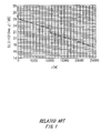
- Fig. 1 shows an example of a result of typical OTDR measurement.
- the transmission loss may abruptly increase when there is a defect in the connection between two optical fibers.
- the region having a high transmission loss is not desirable for transmitting a light signal. It is necessary to re-lay or re-connect the optical fiber in the region having a high transmission loss.
- OTDR measurement it is difficult to accurately measure the transmission loss by the OTDR method if only one side of the backscattering light, which is input to one side of the end of the optical fiber and returned to this side of the end of the optical fiber, is measured.
- the measurement of the transmission loss by the OTDR method is referred to as OTDR measurement.
- the factor, which influences the strength of the backscattering light is not limited to the transmission loss ⁇ (z).
- the fluctuation in the backscattering-light-collect-coefficient B(z) also influences the strength of the backscattering light.
- the waveform of the light that propagates through the optical fiber fluctuates when the backscattering-light-collect-coefficient B(z) fluctuates.
- Equation (5) a value of D(z) is obtained by the following equation (5).
- the factor of the backscattering-light-collect-coefficient B(z) is canceled out by adding the values of the backscattering-light-strengths S 1 ( ⁇ , z) and S 2 ( ⁇ , z-L). Therefore, only the component of the transmission loss ⁇ remains in equation (5).
- this part may be mistakenly considered to have a high transmission loss even if the transmission loss is actually low in this part.
- an object of the present invention to provide an optical fiber capable of easily specifying a part with a problem of transmission loss by OTDR measurement from only one end of an optical fiber and to provide an optical fiber base material to manufacture such a fiber and an evaluation method thereof.
- a method for determining a cause of defect in an unused optical fiber comprises measuring backscattering-light-strengths S( ⁇ 1 , z) and S( ⁇ 2 , z) of the optical fiber for two wavelengths ⁇ 1 and ⁇ 2 , where ⁇ 1 ⁇ ⁇ 2 from both ends of the optical fiber; calculating an amount of change in a backscattering-light-collect-coefficient I( ⁇ 2 , z) and I( ⁇ 1 , z) for the two wavelength ⁇ 1 and ⁇ 2 ; comparing the amount of change in a backscattering-light-collect-coefficient I( ⁇ 1 , z) and I( ⁇ 2 , z) for the two wavelengths ⁇ 1 and ⁇ 2 to examine whether the amount of change in a backscattering-light-collect-coefficient I( ⁇ 1 , z) and I( ⁇ 2 , z) satisfy a predetermined relationship; and determining the cause of
- a method for manufacturing an optical fiber comprises drawing a glass base material, which is a base material of the optical fiber having a core and a clad that surrounds the core, to form the optical fiber; measuring an amount of change in a backscattering-light-collect-coefficient in a longitudinal direction of the optical fiber; removing the optical fiber, in which an absolute value of the amount of change in a backscattering-light-collect-coefficient
- This macro bending loss is a phenomenon, in which a part of the light that propagates in the optical fiber escapes from the optical fiber when the optical fiber is bent with an order between 1 mm and 100 mm. This phenomenon of the macro bending loss is observed as a transmission loss.
- micro bending loss against the bending of a diameter of 32 mm ⁇ for one lap should be 1 dB or less according to G.652 of ITU-T (Telecommunication standardization sector of international telecommunication union), which is an international standard.
- connection loss Another factor of the problem on the transmission loss of the optical fiber is a connection loss.
- the connection loss occurs when the overlapped two power distribution of the light in two optical fibers are not matched with each other at the connection point of two optical fibers.
- One of the causes of the connection loss is a gap created between two-core axes of two optical fibers at the connection point of two optical fibers.
- connection loss 0.2 dB occurs when two core axes of two optical fibers are connected with a gap of 1 ⁇ m.
- the optical fiber itself is made so that a part of the optical fiber having a transmission loss more than substantially 0.1 dB can be easily detected by measuring the incidental light of one end using the OTDR measurement method.
- Figs. 2 to 4E show the detailed procedure of the OTDR measurement method.
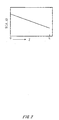
- the vertical axis indicates a backscattering-light-strength S( ⁇ , z)
- the horizontal axis indicates a distance "z" from an incident end face of the optical fiber.
- "L” is a length of the optical fiber.
- the vertical axis indicates a D(z) calculated by the equation (11).
- the vertical axis of Fig. 4D indicates I( ⁇ , z), which is an amount of change in a backscattering-light-collect-coefficient B(z).
- the vertical axis of Fig. 4E indicates a value of MFD.
- the backscattering-light-strength S( ⁇ , z) decreases linearly in the longitudinal direction of the optical fiber when the transmission loss is constant over the whole length of the optical fiber.
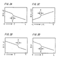
- Figs. 3A and 3B show the change of the backscattering-light-strength S( ⁇ , z) along the longitudinal direction of the optical fiber when there is a part that has high transmission loss in the optical fiber.
- Fig. 3A shows the backscattering-light-strength S( ⁇ , z), which is measured from one end of the optical fiber.
- Fig. 3B shows the backscattering-light-strength S( ⁇ , z), which is measured from another end of the optical fiber.
- Fig. 3C shows the backscattering-light-strength S( ⁇ , z-L), which is obtained by reversing Fig. 3B in the horizontal direction.
- the distance “z" of "0” is on the left hand side in Fig. 3B, and it becomes the right hand side in Fig. 3C.
- the distance “z” of "L” is on the right hand side in Fig. 3B, and it becomes the left hand side in Fig. 3C.
- Fig. 3D shows a value of D(z), which changes in a longitudinal direction of the optical fiber.
- the value of D(z) is calculated by the above-mentioned equation (5) from the values of the backscattering-light-strengths S( ⁇ ,z) and S( ⁇ ,z-L) shown in Figs. 3A and 3C.
- the inclination of D(z) increases greatly at the part marked by "X". Therefore, the part having a high transmission loss, which is marked by "X", can be detected.
- Figs. 4A and 4B show the backscattering-light-strengths S( ⁇ , z) along a longitudinal direction of the optical fiber when there is a part, in which the backscattering-light-collect-coefficient B changes.
- Fig. 4A shows the backscattering-light-strength S( ⁇ , z), which is measured from one end of the optical fiber.
- Fig. 4B shows the backscattering-light-strength S( ⁇ , z), which is measured from another end of the optical fiber.
- Figs. 4A and 4B the inclination of the change in the backscattering-light-strength S( ⁇ , z) changes at the part marked by "Y". Furthermore, the direction of the inclination of the change in the backscattering-light-strength S( ⁇ , z) is different between Figs. 4A and 4B. For example, in Fig. 4A, the backscattering-light-strength S( ⁇ , z) decreases at the part marked by "Y". In contrast, in Fig. 4B, backscattering-light-strength S( ⁇ , z) increases at the part marked by "Y".
- Fig. 4C shows the change in D(z) along the longitudinal direction of the optical fiber.
- Fig. 4C is calculated from the values in Figs. 4A and 4B using the same method as explained in Figs. 3A to 3D.
- the change in the backscattering-light-strength S( ⁇ , z) at the part marked by "Y" is canceled out.
- the backscattering-light-strength S( ⁇ , z) decreases linearly for the whole length of the optical fiber. Therefore, as clearly shown in Fig. 4C, the transmission loss is not changed at the part marked by "Y".
- the cause of the change in the inclination of the backscattering-light-strength S( ⁇ , z) is not a transmission loss but a change in the backscattering-light-collect-coefficient B.
- Fig. 4D shows an amount of change in the backscattering-light-collect-coefficient I( ⁇ , z).
- the amount of change in the backscattering-light-collect-coefficient I( ⁇ , z) is calculated by the following equation (6).
- the backscattering-light-collect-coefficient B is calculated by the following equation (7).
- the cause of the fluctuation in the backscattering-light-collect-coefficient B is the fluctuation in mode field diameter (MFD).
- MFD mode field diameter
- Fig. 4E shows an MFD measured along the longitudinal direction of the optical fiber.
- An MFD is measured by cutting an optical fiber along a longitudinal direction. It can be understood from Figs. 4D and 4E that the cause of the fluctuation in the I( ⁇ , z) is the fluctuation in the MFD value because when the MFD value abruptly changes at the part marked by "Y", the value of the I( ⁇ , z) also abruptly changes at the part marked by "Y".
- the transmission loss in the optical fiber can be detected by measuring the backscattering-light-strength S( ⁇ , z) from only one end of the optical fiber. Therefore, it is possible to detect the part having a high transmission loss in the optical fiber by the OTDR measurement that measures the backscattering light from only one end of the optical fiber.
- ⁇ n ⁇ (n 1 - n 2 ) / n 1 ⁇ ⁇ 100 [%]
- Another cause is a fluctuation in a diameter of a core of an optical fiber.
- the refractive index distribution of the glass base material is adjusted so as to have a similar shape with that of the optical fiber.
- the fluctuation of each parameter explained above such as relative-refractive-index-difference ⁇ n and a diameter of a core of an optical fiber, may occur in the phase of manufacturing the glass base material.
- the fluctuation of each parameter explained above may also occur in the phase of drawing the glass base material to be an optical fiber.
- the refractive index or the core diameter of a glass base material fluctuates in the phase of manufacturing the glass base material
- the refractive index or the core diameter of the optical fiber manufactured from the glass base material also fluctuates almost the same as the glass base material. Even if the fluctuation of the refractive index or the core diameter is reduced in the phase of manufacturing the glass base material, the refractive index or the core diameter of the optical fiber may fluctuate if a speed of cooling an optical fiber during the drawing process fluctuates.
- the condition of a residual stress inside the optical fiber changes.
- the refractive index distribution of the drawn optical fiber also changes.
- the core diameter of the drawn optical fiber also changes. It is very difficult to cancel the fluctuation of the refractive index distribution or the core diameter of the optical fiber by controlling the drawing process of the optical fiber if the refractive index distribution or the core diameter of the glass base material fluctuates.
- the glass base material is removed from the manufacturing process so that the glass base material having stable values of the above-mentioned parameters is shipped. Furthermore, if a fluctuation of the above-mentioned parameters is recognized in the part of the optical fiber by the test, the fluctuated part of the optical fiber is removed in order to take out only the part of the optical fiber having a stable value of the above-mentioned parameters.
- a glass base material was formed by a VAD method.
- This glass base material was drawn into an optical fiber having a core diameter of 8 ⁇ m. The OTDR measurement is performed on this optical fiber.
- the backscattering-light-collect-coefficient B was calculated using the above-mentioned equation (7).
- the value of I( ⁇ , z) is calculated using the equation (6).
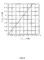
- Fig. 7 shows the change of the relative value of I( ⁇ 1 , z) and I( ⁇ 2 , z) with the rate of change in the relative-refractive-index-difference ⁇ n calculated by the computer simulation.
- the vertical axis shows an absolute or relative value of I( ⁇ 1 , z) and I( ⁇ 2 , z).
- the glass base material or the optical fiber is manufactured such that the rate of change in the relative-refractive-index-difference ⁇ n is substantially 6% or less, then the transmission loss in the optical fiber can be detected by the OTDR measurement from only one end of an optical fiber. Furthermore, the cause of the transmission loss can be detected by comparing the magnitude of
- Figs. 8 to 10 show the result of this OTDR measurement performed on the optical fiber manufactured from the glass base material.
- This glass base material was manufactured such that the outside diameter of the glass base material was fluctuated by the surface treatment using hydrofluoric acid. Then, the glass base material was drawn to have an outside diameter of 125 ⁇ m. Then, the optical fiber having the core diameter, which was fluctuated from a central value of 8 ⁇ m, was obtained. The OTDR measurement was performed on this optical fiber.
- the backscattering-light-collect-coefficient B was calculated using the above-mentioned equation (7).
- the value of I( ⁇ , z) is calculated using the equation (6).
- an absolute or relative value of I( ⁇ , z) is calculated by calculating a difference between the I( ⁇ , z), which is calculated using the fluctuated core diameter, and the reference I( ⁇ , z), which is calculated using the core diameter of 8 ⁇ m.
- Fig. 10 shows a change of absolute or relative value of I( ⁇ 1 , z) and I( ⁇ 2 , z) with the rate of change in the core diameter calculated by the computer simulation.
- the vertical axis shows an absolute or relative value of I( ⁇ 1 , z) and I( ⁇ 2 , z).
- the horizontal axis shows a rate of change in the core diameter from the reference value of the core diameter of 8 ⁇ m.
- the glass base material or the optical fiber is manufactured such that the rate of change in the core diameter is substantially 7% or less. Then, the transmission loss in the optical fiber can be detected by the OTDR measurement from only one end of an optical fiber. Furthermore, the cause of the transmission loss can be detected by comparing the magnitude of the absolute or relative values of
- the cause of the fluctuation in B is the fluctuation in the relative-refractive-index-difference ⁇ n. Also, if
- Fig. 11 shows a flowchart of the manufacturing process of the optical fiber using the present embodiment.
- a porous-glass-base-material is formed by forming a clad around a core by accumulating glass particles on the core (S200).
- a glass base material is formed by sintering and dehydrating the porous-glass-base-material (S202).
- the parameters of the glass base material are measured (S204).
- the parameters there is a rate of change in a relative-refractive-index-difference in a longitudinal direction of the glass base material and the rate of change in the core diameter in a longitudinal direction of the glass base material.
- the glass base material that has the defect part, in which the rate of change in a relative-refractive-index-difference is more than substantially 6% is removed from the manufacturing process of the optical fiber. Also, the glass base material that has the part, in which the rate of change in the core diameter is more than substantially 7%, is removed from the manufacturing process of the optical fiber (S206). Next, the glass base material is drawn into an optical fiber (S210).
- the parameters of the optical fiber are measured (S212).
- the parameters there is a rate of change in a relative-refractive-index-difference in a longitudinal direction of the optical fiber and the rate of change in the core diameter in a longitudinal direction of the optical fiber.
- the cause of defect in an optical fiber can be determined as following. First, the backscattering-light-strengths S( ⁇ 1 , z) and S( ⁇ 2 , z) of the optical fiber for two wavelengths ⁇ 1 and ⁇ 2 , where ⁇ 1 ⁇ ⁇ 2 are measured from both ends of the optical fiber. Then, an amount of change in the backscattering-light-collect-coefficients I( ⁇ 2 , z) and I( ⁇ 1 , z) for the two wavelengths ⁇ 1 and ⁇ 2 are calculated.
- the amount of change in the backscattering-light-collect-coefficients I( ⁇ 1 , z) and I( ⁇ 2 , z) for the two wavelengths ⁇ 1 and ⁇ 2 are compared to examine whether the amount of change in the backscattering-light-collect-coefficients I( ⁇ 1 , z) and I( ⁇ 2 , z) satisfy a predetermined relationship.
- the cause of defect is in a rate of change in a relative-refractive-index-difference of the optical fiber in a longitudinal direction when the relationships of
- the cause of defect is in a rate of change in a core diameter in longitudinal direction of the optical fiber when the relationship of
- the defect part of the optical fiber in which the rate of change in a relative-refractive-index-difference in a longitudinal direction of the optical fiber is more than substantially 6%, is removed from the manufacturing process of the optical fiber.
Landscapes
- Chemical & Material Sciences (AREA)
- Engineering & Computer Science (AREA)
- Physics & Mathematics (AREA)
- Geochemistry & Mineralogy (AREA)
- Manufacturing & Machinery (AREA)
- General Life Sciences & Earth Sciences (AREA)
- Materials Engineering (AREA)
- Organic Chemistry (AREA)
- Life Sciences & Earth Sciences (AREA)
- Optics & Photonics (AREA)
- General Physics & Mathematics (AREA)
- Analytical Chemistry (AREA)
- Chemical Kinetics & Catalysis (AREA)
- General Chemical & Material Sciences (AREA)
- Optical Fibers, Optical Fiber Cores, And Optical Fiber Bundles (AREA)
- Testing Of Optical Devices Or Fibers (AREA)
- Manufacture, Treatment Of Glass Fibers (AREA)
Applications Claiming Priority (3)
| Application Number | Priority Date | Filing Date | Title |
|---|---|---|---|
| JP2001108941 | 2001-04-06 | ||
| JP2001108941A JP2002303741A (ja) | 2001-04-06 | 2001-04-06 | シングルモード光ファイバ用ガラス母材及びシングルモード光ファイバ並びにその評価方法 |
| EP02090133A EP1247783A3 (fr) | 2001-04-06 | 2002-04-05 | Préformes et fibres optiques et procédés de leur fabrication ainsi qu'un procédé pour déterminer la cause d'un défaut |
Related Parent Applications (2)
| Application Number | Title | Priority Date | Filing Date |
|---|---|---|---|
| EP02090133.6 Division | 2002-04-05 | ||
| EP02090133A Division EP1247783A3 (fr) | 2001-04-06 | 2002-04-05 | Préformes et fibres optiques et procédés de leur fabrication ainsi qu'un procédé pour déterminer la cause d'un défaut |
Publications (2)
| Publication Number | Publication Date |
|---|---|
| EP1586884A2 true EP1586884A2 (fr) | 2005-10-19 |
| EP1586884A3 EP1586884A3 (fr) | 2007-08-01 |
Family
ID=18960989
Family Applications (3)
| Application Number | Title | Priority Date | Filing Date |
|---|---|---|---|
| EP05090192A Withdrawn EP1586884A3 (fr) | 2001-04-06 | 2002-04-05 | Procédé pour déterminer la cause d'un défaut d'une fibre optique et procédé de fabrication d'une fibre optique |
| EP05090193A Withdrawn EP1595854A3 (fr) | 2001-04-06 | 2002-04-05 | Préformes et fibres optiques et procédés de leur fabrication |
| EP02090133A Withdrawn EP1247783A3 (fr) | 2001-04-06 | 2002-04-05 | Préformes et fibres optiques et procédés de leur fabrication ainsi qu'un procédé pour déterminer la cause d'un défaut |
Family Applications After (2)
| Application Number | Title | Priority Date | Filing Date |
|---|---|---|---|
| EP05090193A Withdrawn EP1595854A3 (fr) | 2001-04-06 | 2002-04-05 | Préformes et fibres optiques et procédés de leur fabrication |
| EP02090133A Withdrawn EP1247783A3 (fr) | 2001-04-06 | 2002-04-05 | Préformes et fibres optiques et procédés de leur fabrication ainsi qu'un procédé pour déterminer la cause d'un défaut |
Country Status (4)
| Country | Link |
|---|---|
| US (3) | US7035514B2 (fr) |
| EP (3) | EP1586884A3 (fr) |
| JP (1) | JP2002303741A (fr) |
| CA (1) | CA2380715A1 (fr) |
Cited By (1)
| Publication number | Priority date | Publication date | Assignee | Title |
|---|---|---|---|---|
| WO2012064736A1 (fr) * | 2010-11-09 | 2012-05-18 | Adc Telecommunications, Inc. | Test d'un câble optique par réflectométrie optique dans le domaine temporel |
Families Citing this family (5)
| Publication number | Priority date | Publication date | Assignee | Title |
|---|---|---|---|---|
| JPWO2005012967A1 (ja) | 2003-08-04 | 2007-09-27 | 住友電気工業株式会社 | 光ファイバ |
| TW200508678A (en) | 2003-08-04 | 2005-03-01 | Sumitomo Electric Industries | Optical transmission line constituting method, optical transmission line and optical fiber |
| JP4268115B2 (ja) * | 2004-10-28 | 2009-05-27 | 古河電気工業株式会社 | シングルモード光ファイバ |
| GB2540055A (en) * | 2014-04-03 | 2017-01-04 | Halliburton Energy Services Inc | Composite slickline cable integrity testing |
| WO2018210784A1 (fr) * | 2017-05-17 | 2018-11-22 | Radiometer Medical Aps | Fibre optique poreuse pour la détection d'un analyte dans un fluide |
Family Cites Families (20)
| Publication number | Priority date | Publication date | Assignee | Title |
|---|---|---|---|---|
| US3865564A (en) * | 1973-07-09 | 1975-02-11 | Bell Telephone Labor Inc | Fabrication of glass fibers from preform by lasers |
| JPS52121335A (en) * | 1976-04-06 | 1977-10-12 | Nippon Telegr & Teleph Corp <Ntt> | Optical fiber drawing apparatus |
| JPS59217642A (ja) * | 1983-05-23 | 1984-12-07 | Furukawa Electric Co Ltd:The | 光フアイバの紡糸方法 |
| US5221309A (en) * | 1984-05-15 | 1993-06-22 | Sumitomo Electric Industries, Ltd. | Method for producing glass preform for optical fiber |
| DE3625731A1 (de) * | 1986-07-30 | 1988-02-11 | Kabelmetal Electro Gmbh | Verfahren zur herstellung von lichtwellenleitern |
| JPH01100034A (ja) | 1987-10-14 | 1989-04-18 | Hitachi Cable Ltd | 光ファイバ母材の製造装置 |
| JP2652700B2 (ja) * | 1989-02-10 | 1997-09-10 | 住友電気工業株式会社 | 光ファイバの製造方法 |
| US4936675A (en) * | 1989-05-14 | 1990-06-26 | The United States Of America As Represented By The Secretary Of The Navy | Calibrated bender for fiber optic cable position determination |
| US5191206A (en) * | 1991-04-16 | 1993-03-02 | Electric Power Research Institute, Inc. | Distributed fiber optic sensor using clad material light backscattering |
| US5558692A (en) * | 1994-07-25 | 1996-09-24 | Corning Incorporated | Optical waveguide preform measurement during manufacture |
| JP3207323B2 (ja) | 1994-09-12 | 2001-09-10 | 信越化学工業株式会社 | 光ファイバの試験方法 |
| US6131414A (en) * | 1997-05-13 | 2000-10-17 | Shin-Etsu Chemical Co., Ltd. | Method for making a preform for optical fibers by drawing a mother ingot |
| EP1044173A4 (fr) * | 1997-12-23 | 2005-03-09 | Spectran Corp | Procede de fabrication a grande echelle de preformes de fibres optiques dotees de caracteristiques ameliorees |
| JP2000281379A (ja) * | 1999-03-31 | 2000-10-10 | Mitsubishi Cable Ind Ltd | 光ファイバの線引装置 |
| EP1134572B1 (fr) | 1999-09-06 | 2006-11-15 | Anritsu Corporation | Systeme de mesure de la dispersion des longueurs d'ondes de fibres optiques |
| US20020069674A1 (en) * | 2000-12-13 | 2002-06-13 | Guy Patricia C. | Methods and apparatus for automated manufacture of optical fiber |
| WO2002063350A2 (fr) | 2001-02-07 | 2002-08-15 | Omniguide Communications | Controle de guide d'ondes optiques |
| JP4540923B2 (ja) * | 2001-11-09 | 2010-09-08 | 株式会社フジクラ | 光ファイバの製造方法および光ファイバ母材の製造方法 |
| US6717659B2 (en) | 2002-06-14 | 2004-04-06 | Fitel Usa Corp. | Method and apparatus for detecting airlines in optical fibers |
| US7234259B2 (en) * | 2003-01-13 | 2007-06-26 | Anna Jee Lee | Three-dimensional album page protector |
-
2001
- 2001-04-06 JP JP2001108941A patent/JP2002303741A/ja active Pending
-
2002
- 2002-04-05 EP EP05090192A patent/EP1586884A3/fr not_active Withdrawn
- 2002-04-05 EP EP05090193A patent/EP1595854A3/fr not_active Withdrawn
- 2002-04-05 EP EP02090133A patent/EP1247783A3/fr not_active Withdrawn
- 2002-04-05 CA CA002380715A patent/CA2380715A1/fr not_active Abandoned
- 2002-04-05 US US10/116,744 patent/US7035514B2/en not_active Expired - Lifetime
-
2004
- 2004-04-07 US US10/819,331 patent/US6914669B2/en not_active Expired - Fee Related
- 2004-12-16 US US11/012,345 patent/US7698908B2/en not_active Expired - Lifetime
Non-Patent Citations (4)
| Title |
|---|
| GOLD M P ET AL: "Analysis of backscatter waveforms from single-mode fibres" EUROPEAN CONFERENCE ON OPTICAL COMMUNICATION CONFERENCE EUROPEENNE SUR LES COMMUNICATIONS OPTIQUES PARIS, FRANCE, 1982, pages 633-638, XP008076495 * |
| HARTOG A H ET AL: "On the theory of backscattering in single-mode optical fibers" JOURNAL OF LIGHTWAVE TECHNOLOGY USA, vol. LT-2, no. 2, April 1984 (1984-04), pages 76-82, XP002425410 ISSN: 0733-8724 * |
| KOLLE U ET AL: "DAS OTDR ALS UNIVERSALMESSGERAET FUER LICHTWELLENLEITER" NTZ (NACHRICHTENTECHNISCHE ZEITSCHRIFT), VDE VERLAG GMBH., BERLIN, DE, vol. 52, no. 1/2, 1999, pages 64-65, XP000804537 ISSN: 0948-728X * |
| OHASHI M ET AL: "NOVEL TECHNIQUE FOR MEASURING LONGITUDINAL CHROMATIC DISPERSION DISTRIBUTION IN SINGLEMODE FIBRES" ELECTRONICS LETTERS, IEE STEVENAGE, GB, vol. 29, no. 5, 4 March 1993 (1993-03-04), pages 426-428, XP000349845 ISSN: 0013-5194 * |
Cited By (2)
| Publication number | Priority date | Publication date | Assignee | Title |
|---|---|---|---|---|
| WO2012064736A1 (fr) * | 2010-11-09 | 2012-05-18 | Adc Telecommunications, Inc. | Test d'un câble optique par réflectométrie optique dans le domaine temporel |
| US8654321B2 (en) | 2010-11-09 | 2014-02-18 | Adc Telecommunications, Inc. | Testing of optical cable using optical time domain reflectometry |
Also Published As
| Publication number | Publication date |
|---|---|
| JP2002303741A (ja) | 2002-10-18 |
| EP1247783A2 (fr) | 2002-10-09 |
| CA2380715A1 (fr) | 2002-10-06 |
| US6914669B2 (en) | 2005-07-05 |
| US20050123256A1 (en) | 2005-06-09 |
| US20020176675A1 (en) | 2002-11-28 |
| EP1595854A3 (fr) | 2007-05-16 |
| EP1595854A2 (fr) | 2005-11-16 |
| EP1247783A3 (fr) | 2002-10-23 |
| US7698908B2 (en) | 2010-04-20 |
| US20040190852A1 (en) | 2004-09-30 |
| EP1586884A3 (fr) | 2007-08-01 |
| US7035514B2 (en) | 2006-04-25 |
Similar Documents
| Publication | Publication Date | Title |
|---|---|---|
| US8547541B2 (en) | Method for the characterization of optical properties of an optical fiber | |
| CN102939522B (zh) | 检查弯曲不敏感光缆的正确安装的方法和适用于该方法的光缆 | |
| CN110462476A (zh) | 采用混合纤芯光纤的分布式光纤传感器和系统 | |
| JP2005518564A (ja) | ブロードバンドアクセス用ファイバ及びその製造方法 | |
| US9175946B2 (en) | Measuring method of hole diameter, hole position, hole surface roughness, or bending loss of holey optical fiber, manufacturing method of holey optical fiber, and test method of optical line of holey optical fiber | |
| US7035514B2 (en) | Glass base material, optical fiber, method for manufacturing thereof, and method for determining cause of defect thereof | |
| US7177512B2 (en) | Solid type polarization maintaining fiber and apparatus | |
| JP2001516021A (ja) | 偏波モード分散の高いレベルを示す光ファイバの識別方法 | |
| US7298934B2 (en) | Optical fiber and method of measuring polarization mode dispersion of optical fiber | |
| JP5770517B2 (ja) | 光ファイバのカットオフ波長測定方法 | |
| JP2025506457A (ja) | 中空コア光ファイバのための光時間領域反射測定 | |
| JP4109574B2 (ja) | 光ファイバ伝送路の損失特性評価方法 | |
| US9753216B2 (en) | Multimode optical fiber and optical cable including the same | |
| Ratuszek | Analysis of reflectometric measurements losses of spliced single mode telecommunication fibers with significantly different parameters. | |
| JP3388496B2 (ja) | 単一モード光ファイバの特性評価方法 | |
| JP2015007710A (ja) | 光ファイバ、光ファイバ伝送路、光ファイバ伝送路の接続方法 | |
| Coppa et al. | Characterization of single-mode optical fibres | |
| JPH0968479A (ja) | 光ファイバ構造定数測定方法 | |
| Coppa et al. | Single-mode optical fiber characterization | |
| JP2004354103A (ja) | 光ファイバ伝送路の損失波長特性の推定方法 | |
| JPH04151532A (ja) | 光ファイバの試験方法 | |
| Brininstool | Techniques for measuring longitudinal strain in graded index optical fibers | |
| JP2001041855A (ja) | 光ファイバ伝送路の特性評価方法及び装置 | |
| JP2007225468A (ja) | 光ファイバの状況判定方法 | |
| JP2009025824A (ja) | シングルモード光ファイバ用ガラス母材及びシングルモード光ファイバ |
Legal Events
| Date | Code | Title | Description |
|---|---|---|---|
| PUAI | Public reference made under article 153(3) epc to a published international application that has entered the european phase |
Free format text: ORIGINAL CODE: 0009012 |
|
| AC | Divisional application: reference to earlier application |
Ref document number: 1247783 Country of ref document: EP Kind code of ref document: P |
|
| AK | Designated contracting states |
Kind code of ref document: A2 Designated state(s): DE FR GB |
|
| AX | Request for extension of the european patent |
Extension state: AL LT LV MK RO SI |
|
| RIC1 | Information provided on ipc code assigned before grant |
Ipc: C03B 37/025 20060101ALI20070321BHEP Ipc: G01M 11/00 20060101AFI20050812BHEP |
|
| PUAL | Search report despatched |
Free format text: ORIGINAL CODE: 0009013 |
|
| AK | Designated contracting states |
Kind code of ref document: A3 Designated state(s): DE FR GB |
|
| AX | Request for extension of the european patent |
Extension state: AL LT LV MK RO SI |
|
| 17P | Request for examination filed |
Effective date: 20071011 |
|
| AKX | Designation fees paid |
Designated state(s): DE FR GB |
|
| 17Q | First examination report despatched |
Effective date: 20080908 |
|
| STAA | Information on the status of an ep patent application or granted ep patent |
Free format text: STATUS: THE APPLICATION IS DEEMED TO BE WITHDRAWN |
|
| 18D | Application deemed to be withdrawn |
Effective date: 20110219 |