EP1585107B1 - Hybrides Blasinstrument, das wahlweise akustische Töne und elektronische Töne produziert, und elektronisches System dafür - Google Patents
Hybrides Blasinstrument, das wahlweise akustische Töne und elektronische Töne produziert, und elektronisches System dafür Download PDFInfo
- Publication number
- EP1585107B1 EP1585107B1 EP05004215A EP05004215A EP1585107B1 EP 1585107 B1 EP1585107 B1 EP 1585107B1 EP 05004215 A EP05004215 A EP 05004215A EP 05004215 A EP05004215 A EP 05004215A EP 1585107 B1 EP1585107 B1 EP 1585107B1
- Authority
- EP
- European Patent Office
- Prior art keywords
- mouthpiece
- player
- acoustic
- set forth
- quasi
- Prior art date
- Legal status (The legal status is an assumption and is not a legal conclusion. Google has not performed a legal analysis and makes no representation as to the accuracy of the status listed.)
- Ceased
Links
- 230000009471 action Effects 0.000 claims description 20
- 230000007246 mechanism Effects 0.000 claims description 17
- 230000005236 sound signal Effects 0.000 claims description 12
- 230000005355 Hall effect Effects 0.000 claims description 10
- 210000003811 finger Anatomy 0.000 claims description 10
- 210000000056 organ Anatomy 0.000 claims description 5
- 210000003813 thumb Anatomy 0.000 claims description 5
- 238000012544 monitoring process Methods 0.000 claims description 3
- 230000008859 change Effects 0.000 claims description 2
- 235000014676 Phragmites communis Nutrition 0.000 description 10
- 238000007664 blowing Methods 0.000 description 8
- 230000015654 memory Effects 0.000 description 6
- 230000000875 corresponding effect Effects 0.000 description 4
- 230000002093 peripheral effect Effects 0.000 description 4
- 230000003936 working memory Effects 0.000 description 4
- 230000000694 effects Effects 0.000 description 3
- 210000000214 mouth Anatomy 0.000 description 3
- 230000000644 propagated effect Effects 0.000 description 3
- 238000004590 computer program Methods 0.000 description 2
- 230000000994 depressogenic effect Effects 0.000 description 2
- 230000029058 respiratory gaseous exchange Effects 0.000 description 2
- XLYOFNOQVPJJNP-UHFFFAOYSA-N water Substances O XLYOFNOQVPJJNP-UHFFFAOYSA-N 0.000 description 2
- 229910001369 Brass Inorganic materials 0.000 description 1
- 239000010951 brass Substances 0.000 description 1
- 230000002596 correlated effect Effects 0.000 description 1
- 230000007423 decrease Effects 0.000 description 1
- 230000001419 dependent effect Effects 0.000 description 1
- 230000014509 gene expression Effects 0.000 description 1
- 210000000088 lip Anatomy 0.000 description 1
- 210000004072 lung Anatomy 0.000 description 1
- 238000012986 modification Methods 0.000 description 1
- 230000004048 modification Effects 0.000 description 1
- 230000003287 optical effect Effects 0.000 description 1
- 239000013589 supplement Substances 0.000 description 1
- 210000002105 tongue Anatomy 0.000 description 1
- 239000002023 wood Substances 0.000 description 1
Images


Classifications
-
- G—PHYSICS
- G10—MUSICAL INSTRUMENTS; ACOUSTICS
- G10H—ELECTROPHONIC MUSICAL INSTRUMENTS; INSTRUMENTS IN WHICH THE TONES ARE GENERATED BY ELECTROMECHANICAL MEANS OR ELECTRONIC GENERATORS, OR IN WHICH THE TONES ARE SYNTHESISED FROM A DATA STORE
- G10H1/00—Details of electrophonic musical instruments
- G10H1/32—Constructional details
-
- G—PHYSICS
- G10—MUSICAL INSTRUMENTS; ACOUSTICS
- G10H—ELECTROPHONIC MUSICAL INSTRUMENTS; INSTRUMENTS IN WHICH THE TONES ARE GENERATED BY ELECTROMECHANICAL MEANS OR ELECTRONIC GENERATORS, OR IN WHICH THE TONES ARE SYNTHESISED FROM A DATA STORE
- G10H1/00—Details of electrophonic musical instruments
- G10H1/02—Means for controlling the tone frequencies, e.g. attack or decay; Means for producing special musical effects, e.g. vibratos or glissandos
- G10H1/04—Means for controlling the tone frequencies, e.g. attack or decay; Means for producing special musical effects, e.g. vibratos or glissandos by additional modulation
- G10H1/053—Means for controlling the tone frequencies, e.g. attack or decay; Means for producing special musical effects, e.g. vibratos or glissandos by additional modulation during execution only
- G10H1/055—Means for controlling the tone frequencies, e.g. attack or decay; Means for producing special musical effects, e.g. vibratos or glissandos by additional modulation during execution only by switches with variable impedance elements
-
- G—PHYSICS
- G10—MUSICAL INSTRUMENTS; ACOUSTICS
- G10H—ELECTROPHONIC MUSICAL INSTRUMENTS; INSTRUMENTS IN WHICH THE TONES ARE GENERATED BY ELECTROMECHANICAL MEANS OR ELECTRONIC GENERATORS, OR IN WHICH THE TONES ARE SYNTHESISED FROM A DATA STORE
- G10H1/00—Details of electrophonic musical instruments
- G10H1/32—Constructional details
- G10H1/34—Switch arrangements, e.g. keyboards or mechanical switches specially adapted for electrophonic musical instruments
-
- G—PHYSICS
- G10—MUSICAL INSTRUMENTS; ACOUSTICS
- G10H—ELECTROPHONIC MUSICAL INSTRUMENTS; INSTRUMENTS IN WHICH THE TONES ARE GENERATED BY ELECTROMECHANICAL MEANS OR ELECTRONIC GENERATORS, OR IN WHICH THE TONES ARE SYNTHESISED FROM A DATA STORE
- G10H2220/00—Input/output interfacing specifically adapted for electrophonic musical tools or instruments
- G10H2220/155—User input interfaces for electrophonic musical instruments
- G10H2220/361—Mouth control in general, i.e. breath, mouth, teeth, tongue or lip-controlled input devices or sensors detecting, e.g. lip position, lip vibration, air pressure, air velocity, air flow or air jet angle
-
- G—PHYSICS
- G10—MUSICAL INSTRUMENTS; ACOUSTICS
- G10H—ELECTROPHONIC MUSICAL INSTRUMENTS; INSTRUMENTS IN WHICH THE TONES ARE GENERATED BY ELECTROMECHANICAL MEANS OR ELECTRONIC GENERATORS, OR IN WHICH THE TONES ARE SYNTHESISED FROM A DATA STORE
- G10H2220/00—Input/output interfacing specifically adapted for electrophonic musical tools or instruments
- G10H2220/461—Transducers, i.e. details, positioning or use of assemblies to detect and convert mechanical vibrations or mechanical strains into an electrical signal, e.g. audio, trigger or control signal
- G10H2220/521—Hall effect transducers or similar magnetic field sensing semiconductor devices, e.g. for string vibration sensing or key movement sensing
-
- G—PHYSICS
- G10—MUSICAL INSTRUMENTS; ACOUSTICS
- G10H—ELECTROPHONIC MUSICAL INSTRUMENTS; INSTRUMENTS IN WHICH THE TONES ARE GENERATED BY ELECTROMECHANICAL MEANS OR ELECTRONIC GENERATORS, OR IN WHICH THE TONES ARE SYNTHESISED FROM A DATA STORE
- G10H2230/00—General physical, ergonomic or hardware implementation of electrophonic musical tools or instruments, e.g. shape or architecture
- G10H2230/045—Special instrument [spint], i.e. mimicking the ergonomy, shape, sound or other characteristic of a specific acoustic musical instrument category
- G10H2230/155—Spint wind instrument, i.e. mimicking musical wind instrument features; Electrophonic aspects of acoustic wind instruments; MIDI-like control therefor
- G10H2230/205—Spint reed, i.e. mimicking or emulating reed instruments, sensors or interfaces therefor
- G10H2230/221—Spint saxophone, i.e. mimicking conical bore musical instruments with single reed mouthpiece, e.g. saxophones, electrophonic emulation or interfacing aspects therefor
-
- G—PHYSICS
- G10—MUSICAL INSTRUMENTS; ACOUSTICS
- G10H—ELECTROPHONIC MUSICAL INSTRUMENTS; INSTRUMENTS IN WHICH THE TONES ARE GENERATED BY ELECTROMECHANICAL MEANS OR ELECTRONIC GENERATORS, OR IN WHICH THE TONES ARE SYNTHESISED FROM A DATA STORE
- G10H2250/00—Aspects of algorithms or signal processing methods without intrinsic musical character, yet specifically adapted for or used in electrophonic musical processing
- G10H2250/315—Sound category-dependent sound synthesis processes [Gensound] for musical use; Sound category-specific synthesis-controlling parameters or control means therefor
- G10H2250/461—Gensound wind instruments, i.e. generating or synthesising the sound of a wind instrument, controlling specific features of said sound
- G10H2250/465—Reed instrument sound synthesis, controlling specific features of said sound
Definitions
- This invention relates to a wind instrument and, more particularly, to a hybrid wind instrument for selectively producing electronic tones and acoustic tones.
- a wind instrument is defined in a dictionary of music as "musical instruments in which the sound is produced through the vibrations of a column of air which is set in motion by the player's breath".
- acoustic tones means tones which are produced through the vibrations of the column of air.
- electric tones means tones which are covered from an electric signal.
- the loud tones are radiated from the wind instrument, and the neighborhood feels such loud tones irritating.
- the mutes merely reduce the loudness so that the neighborhood still feels the tones noisy.
- An electronic wind instrument is effective against the nuisance.
- the electronic wind instrument is equipped with a lip sensor, a breath sensor and key sensors, and a data processor analyzes pieces of performance data representative of the actions of the lip and tongue, the pressure of breath and fingering on the keys for producing music data codes.
- the music data codes are supplied to an electronic tone generator, and an audio signal is produced on the basis of the music data codes through the electronic tone generator.
- the audio signal is supplied to a sound system so as to be converted to the electric tones. The loudness is easily controlled through the sound system.
- the prior art electronic wind instrument includes a long tube-like body, a mouthpiece, a key mechanism, control switches and an electronic tone generating system.
- the mouthpiece is attached to one end of the long bar-like body, and the key mechanism and control switches are provided on the obverse surface and reverse surface of the long tube-like body.
- the mouthpiece is equipped with the lip sensor and breath sensor, and is connected through a drainpipe to an exhaust hole, which is formed in the lower portion of the long tube-like body.
- the lip sensor supplies a detecting signal, which represents how the player keeps the mouthpiece between his or her lips, to the data processor, and the breath sensor reports the pressure of the air to the data processor.
- the player specifies the pitch of tones to be produced through the key mechanism.
- the key action is detected with key sensors, and detecting signals are also supplied from the key sensors to the data processor.
- the data processor analyzes these pieces of music data, and produces MIDI (Musical Instrument Digital Interface) music data codes through the analysis.
- the MIDI music data codes are output from the MIDI-out terminal to a sound system or another electronic musical instrument.
- the fingering on the key mechanism is analogous to that on a saxophone or a recorder.
- the lip sensor and breath sensor can merely discriminate some labial actions from each other.
- the pieces of performance data which are brought to the data processor through the detecting signals, are not enough to produce the electric tones in various artificial expressions.
- the player wishes to impart the pitch bend effect to the tones, he or she rotates a bend wheel, which is provided on the reverse surface of the long tube-like body.
- the player pushes a key hold switch, which is also provided on the reverse surface, for prolonging the electric tones. Due to these differences, even if a player has been experienced in the acoustic wind instrument, it is difficult to play a piece of music on the prior art electronic wind instrument. This is the problem inherent in the prior art electronic wind instrument.
- Synthophone Zone website including the Synthophone specification and manual, Softwind Instruments, archived on April 4, 2001 by Archive.org at http://web.archive.org/web/20010404034714/home.att.net/ ⁇ synthophone, XP002393502 was used as a basis for the preamble of the independent claims 1 and 13.
- US-A-5,340,942 and US-A-3,767,833 A musical tone synthesizer is disclosed in US-A-5,340,942 .
- the mouthpiece is not replaceable with an acoustic mouthpiece.
- An electronic musical instrument is disclosed in US-A-3,767,833 .
- the mouthpiece and tubular body have a unitary structure. In other words, the mouthpiece is not replaceable with any acoustic mouthpiece.
- the present invention proposes to add an electronic system to an acoustic wind instrument.
- a wind instrument for selectively producing acoustic tones and electric tones, as set forth in claim 1.
- an electronic system combinable with an acoustic wind instrument as set forth in claim 13.
- Preferred embodiments of the present invention may be gathered from the dependent claims.
- term "upper” is indicative of a relative position closer to the lips of a player, who is performing a piece of music on a hybrid wind instrument, than a position modified with term “lower”.
- a hybrid saxophone embodying the present invention is designated by reference numeral 1.
- the hybrid saxophone 1 largely comprises an acoustic saxophone 2 and an electronic system 4.
- the term "acoustic saxophone” means a standard saxophone, which produces tones through vibrating air column created inside thereof. Acoustic tones are produced through the acoustic saxophone 2, and electric tones are produced in cooperation between the saxophone 2 and the electronic system 4. Thus, the acoustic tones and electric tones are selectively produced through the hybrid saxophone 1.
- the electronic system 4 When a player wishes to do the exercise without disturbing the neighborhood, he or she makes the electronic system 4 enabled to produce the electric tones, and, thereafter, starts to blow and finger a piece of music on the acoustic saxophone 2.
- the electronic system analyzes detecting signals representative of the blowing and fingering on the acoustic saxophone 2 for producing pieces of music data, and produces the electric tones on the basis of the pieces of music data. Since the electronic system 4 offers a volume control to the player, the player can instruct the electronic system 4 faintly to produce the electric tones, and the player hears the faint electric tones without any disturbance to the neighborhood. Since the piece of music is fingered on the acoustic saxophone, players, who are experienced in acoustic saxophone, can perform pieces of music as usual.
- the players selectively produce the acoustic tones and electric tones through the hybrid saxophone according to the present invention. Nevertheless, the players finger pieces of music on the acoustic saxophone for performing the pieces of music through both acoustic and electric tones. This means that the players who are experienced in acoustic saxophone can immediately play the pieces of music on the hybrid saxophone. Moreover, the players can minimize the loudness of the electric tones through the volume control offered by the electronic system 4. In other words, the players can keep the environment silent during the exercises. Thus, the hybrid saxophone 1 is free from the trade-of between the acoustic saxophone and the prior art electronic wind instrument.
- the acoustic saxophone 2 includes a tubular body 10, a mouthpiece 20 and a key mechanism 12.
- the tubular body 10 has a generally J-letter shape, and is open to the air at both ends thereof.
- the inner space, which is defined inside the tubular body, is gradually increased in cross section from the upper end toward the lower end or a bell 10a, and plural tone holes, some of which are labeled with "10b".
- the tone holes 10b define the length of vibrating air column inside the tubular body 10 in cooperation with the key mechanism 12.
- the mouthpiece 20 is connected to the upper end of the tubular body 10, and the key mechanism 12 is provided on the outer surface of the tubular body 10.
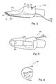
- the upper end of the mouthpiece 20 is thinned like a bill of a water bird, and the player puts the mouthpiece in the mouth for blowing.
- An air passage is formed in the mouthpiece 20, and is open to the outside on the reverse surface of the mouthpiece 20 and the end surface.
- a reed 22 is attached to the reverse surface of the mouthpiece 20 in such a manner as to close the air passage on the reverse surface. While the player is blowing, the breath gives rise to vibrations of the air column, and the vibrations are propagated to the inner space defined in the tubular body 10.
- the key mechanism 12 includes keys 11a, cups 11b and link works 11c.
- the cups 11b are respectively associated with the tone holes 10b, and are connected to the link works 11c.
- the link works 11c are further connected to the keys 11a, and the keys 11a are selectively depressed with the thumbs and fingers of the player.
- the link works 11c propagate the force exerted on the keys 11a to the cups 11b, and make the tone holes 10b selectively open and close.
- the fingering on the keys 11a is similar to that on the keys of a standard saxophone.
- the acoustic saxophone 1 is similar in appearance and structure to a standard saxophone, and the player produces the acoustic tones by blowing into mouthpiece 20 and fingering on the key mechanism 12.
- the electronic system 4 includes a mouthpiece 20A with built-in sensors, a controller 16, an electronic tone generator 4a, a sound system 4b and a sensor system 4c.
- the mouthpiece 20 is replaceable with the mouthpiece 20A with built-in sensors.
- the built-in sensors form parts of the sensor system 4c.
- the sensor system 4c and controller 16 are attached to the acoustic saxophone 2, and the sensor system 4c is electrically connected to the controller 16 so as to supply detecting signals to the controller 16.
- the controller 16 is further connected to the electronic tone generator 4a, and pieces of playing data, which are carried on the detecting signals, are processed through the electronic tone generator 4a so as to produce an audio signal.
- the electronic tone generating system 4a is connected to the sound system 4b, and the audio signal is equalized, amplified and converted to the electric tones.
- the sensor system 4c monitors the lips, tongue, breathing and keys 11, and produces an analog detecting signal representative of the pressure exerted by the lips, an analog detecting signal representative of the tonguing, an analog detecting signal representative of the pressure of the out breath and analog detecting signals representative of the positions of the cups 11b with respect to the tone holes 10b.
- These analog detecting signals are supplied to the controller 16.
- the analog detecting signals are sampled, and are converted to 8-bit digital detecting signals, respectively.
- the digital detecting signals are supplied to the electronic tone generator 4a so that the pieces of playing data are conveyed to the electronic tone generator 4a through the digital detecting signals.
- the electronic tone generator 4a analyzes the pieces of playing data so as to determine the electric tones to be produced.
- the electronic tone generator 4a produces music data codes representative of the electric tones, and in turn generates the audio signal on the basis of the music data codes.
- the audio signal is supplied to the sound system 4b.
- the sound system 4b includes an equalizer, an amplifier and a headphone 4e, and the audio signal is equalized, amplified and converted to the electric tones.
- the sound system 4b may further include loud speakers (not shown). In this instance, the player can perform a piece of music through loud electric tones.
- the mouthpiece 20A includes a body 21 and a reed 22a.
- the body 21 is thinned like the bill of a water bird, and the reed 22a is attached to the reverse surface of the body 21.
- the mouthpiece 20A is similar in appearance to the mouthpiece 20. It is desirable to use the reed 22 as the reed 22a, because the reed 22a makes the player feel the mouthpiece 20A same as the mouthpiece 20.
- the air passage which extends from the reverse surface to the end surface in the mouthpiece 20, is not formed in the mouthpiece 20A. For this reason, the reed 22a does not vibrate, and, accordingly, the acoustic tones are not produced.
- the breath sensor 23a may be referred to as a "wind sensor”.
- the tonguing sensor 23 is implemented by a reflection-type photo coupler or photo reflector, and pressure-sensitive elements are used as the breath sensor 23a and lip sensor 24.
- the tonguing sensor 23 is attached to the bill-like portion, and is exposed to the oral cavity of the player during the performance. Infrared light is radiated from the tonguing sensor 23, and is reflected on the tongue of the player. The reflection is incident on the tonguing sensor 23, and the incident infrared light is converted to photo current. While the player is keeping the tongue spaced from the tonguing sensor 23, a small amount of photo current is produced in the tonguing sensor 23. However, when the player moves the tongue in the vicinity of the tonguing sensor 23, the amount of photo current is increased. Thus, the tonguing sensor 23 increases and decreases the photo current depending upon the distance from the tongue.
- the breath sensor 23a is provided on a wind way. When the player breathes into the mouthpiece 20A, the pressure is exerted on the breath sensor 23a, and breath sensor 23a varies the amount of current passing therethrough depending upon the pressure.
- the lip sensor 24 is attached to the reverse surface of the body 21, and is sandwiched between the reed 22a and the body 21. If the reed 22a is removed from the body 21, the lip sensor 24 is exposed as shown in figure 3 . While the player is playing a piece of music on the hybrid saxophone 1, he or she keeps the bill-like portion in the mouth, and sandwiches it between the lips. Since the player presses the reed 22a to the bill-like portion, the pressure is exerted on the lip sensor 24 so that the lip sensor 24 reports the actions of the lips through the controller 16 to the electronic tone generator 4a.
- the cable 28 extends from the tonguing sensor 23, breath sensor 23a and lip sensor 24, and is taken out from the mouthpiece 20A as shown in figure 1 .
- a suitable connector is provided at the leading end of the cable 28, and another cable (not shown) extends from the controller 16 to an upper end portion of the tubular body 10.
- the other cable (not shown) is covered with a cable holder 17, which is secured to the tubular body 10, and is terminated at a corresponding connector.
- the cable 28 is connected to the other cable through the connectors so that the detecting signals are propagated from the tonguing sensor 23, breath sensor 23a and lip sensor 24 through the cables 28 to the controller 16.
- the cable 28 is jointed to the other cable through the connectors.
- the connectors are released from each other, and the cable 28 is disconnected from the other cable, i.e., the controller 16.
- the mouthpiece 20A is equipped with a rotary air-flow regulator 26.
- the body 21 is formed with a slit 21a, and the rotary air-flow regulator 26 is partially exposed through the slit 21a to the outside.
- the rotary air-flow regulator 26 has a disk shape as shown in figure 4 , and is formed with an orifice 26d.
- the orifice 26d has a horn-like shape.
- the orifice 26d extends along a lower part of the periphery over a distance less than the width of the wind way, and the width, which is measured in the radial direction of the rotary air-flow regulator 26, is gradually increased in the clockwise direction.
- a pair of lug portions 26a projects from the center of the air-flow regulator 26, and a part of the peripheral surface is milled as indicated by reference 26b.
- the corrugated peripheral surface 26b prevents the finger from slippage.
- a stopper 26c radially projects on the opposite side to the corrugated peripheral surface 26b.
- the body 21 is broken down into a cover plate 21b and a bulk 27 as shown in figure 5 .
- the bulk 27 is assembled with the cover plate 21b, and is hardly seen.
- the wind way 27a is formed in the bulk 27, and extends in the longitudinal direction of the bulk 27.
- a sectorial recess 27b is further formed in the bulk 27, and the wind way 27a crosses the sectorial recess 27b.
- the sectorial recess 27b is aligned with the slit 21a, and a deep sectorial groove 27d deepens the bottom of the sectorial recess 27b.
- a pair of grooves 27c is further formed in the bulk 27, and the grooves 27c extend from the sectorial recess 27b in the opposite directions.
- the lugs 26a are rotatably received in the grooves 27c, respectively, and the grooves 27c permit the lugs 26a and, accordingly, rotary air-flow regulator 26 to rotate in the mouthpiece 20A.
- the distance from the grooves 27c to the outer surface of the cover plate 21b is slightly shorter than the radius of curvature of the rotary air-flow regulator 26 so that the corrugated peripheral surface 26b projects through the slit 21a over the outer surface of the cover plate 21b.
- the stopper 26c is inserted in the deep sectorial groove 27d so that the rotation of the rotary air-flow regulator 26 is restricted by the stopper 26c.
- the rotary air-flow regulator 26 can rotate over a predetermined angle defined by both end surfaces for the deep sectorial groove 27d.
- the wind way 27a is overlapped with the orifice 26d.
- the horn-shaped orifice 26d extends over the distance much less than the width of the orifice 26d, and the width of the orifice 26d is varied along the periphery. For this reason, while the player is rotating the rotary air-flow regulator 26, the orifice 26d varies the cross section of the wind way 27a and, accordingly resistance against the breath depending upon the angular position thereof. Thus, the player can control the back-pressure in the mouthpiece 20A by manipulating the rotary air-flow regulator 26.
- the sensor system 4c further includes key sensors 24b for monitoring the actions of the keys 11a.
- the key sensors 24b are implemented by combinations of pieces of magnet 13 and Hall-effect elements 15 as shown in figure 6 .
- a flexible circuit board 14 is secured to the tubular body 10 below the key mechanism 12 (see figure 1 ), and the pieces of magnet 13 are attached to the link works 11c and keys 11a.
- conductive lines 14a are printed on a flexible board 14b, and the Hall-effect elements 15 are provided on the conductive lines 14a.
- the pieces of magnet 13 are respectively opposed to the Hall-effect elements 15, and are selectively moved to the Hall-effect elements 15 in such a manner that the pieces of magnet 13, which are in the proximity of the Hall-effect elements 15, are laid on one of the different patterns depending upon the tone to be produced.
- the piece of magnet 13 is moved to the associated Hall-effect element 15, the associated Hall-effect element 15 makes the potential level on the conductive line varied, and the controller 16 determines the tone to be produced.
- the electronic tone generator 4a includes a microprocessor, a program memory, a working memory, a signal interface, a tone generator and a bus system.
- a computer program is stored in the program memory, and the programmed instructions are sequentially executed by the microprocessor. Parameter tables are further stored in the program memory, and the program memory may be given in the form of a memory card.
- the microprocessor, program memory, working memory, signal interface and tone generator are connected to the bus system, and pieces of data are transferred between these system components through the bus system.
- a cable 16a is connected from the controller 16 to the signal interface so that the digital detecting signals are transferred from the controller 16 through the cable 16a to the signal interface.
- Another cable 4d is further connected between the signal interface and the sound system 4b, and the audio signal is propagated from the signal interface to the sound system 4b.
- the microprocessor periodically fetches the pieces of playing data, which are carried on the digital detecting signals, and stores the pieces of playing data in the working memory.
- the microprocessor analyzes the pieces of playing data in the working memory to see whether or not the player changes the position of the tongue, strength of breath, pressure on the bill-like portion and/ or the depressed/ released keys 11a. When the answer is given affirmative, the microprocessor determines the pitch, loudness and length of the electric tone to be produced, and produces the music data code representative of these pieces of music data representative of the attributes of the electric tone.
- the microprocessor determines the length of tone and loudness on the basis of the pieces of playing data supplied from the tonguing sensor 23 and the pieces of playing data supplied from the breach sensor 23a, respectively.
- the microprocessor can determine the pitch bend without the pitch vend wheel.
- the microprocessor transfers the music data through the bus system to the tone generator.
- Pieces of waveform data are stored in a waveform memory incorporated in the tone generator, and a data reader, which is also incorporated in the tone generator, successively reads out the pieces of waveform data.
- An envelope is given to the series of pieces of waveform data, and the series of pieces of waveform data is converted to the audio signal.
- the audio signal is supplied through the signal interface to the sound system 4b.
- a player wishes to perform a piece of music through the electric tones, he or she replaces the mouthpiece 20 with the mouthpiece 20A, and connects the cable 28 to the other cable (not shown) covered with the cable holder 17.
- the player further connects the cable 16a to the electronic tone generator 4a.
- the player rotates the rotary air-flow regulator 26, and adjusts the resistance against the breath to a value approximately equal to that of a standard saxophone, with which he or she is familiar. Then, the player starts to perform a piece of music.
- the breath sensor 23a, lip sensor 24 and tonguing sensor 23 vary the potential level of the analog detecting signals, and the controller 16 transfers the pieces of playing data through the digital detecting signal to the electronic tone generator 4a.
- the player selectively depresses and releases the keys 11a during the performance, and the key sensors 24b inform the key actions through the controller 16 to the electronic tone generator 4a.
- the player feels the blowing as similar to that into the standard saxophone, and the fingering on the keys 11a are same as that on the standard saxophone.
- the player is assumed to wish to impart the pitch bend effect to the electric tone. He or she blows and manipulates the keys 11a as similar to those on the standard saxophone. Since the lip sensor 24 gives an additional piece of playing data to the electronic tone generator 4a, the microprocessor requests the tone generator to give the pitch bend to the electric tone.
- the player can play a piece of music on the hybrid saxophone selectively through the acoustic tones and corresponding electric tones.
- the blowing and fingering are not different from those on the standard saxophone so that the players easily play the hybrid saxophone.
- the lip sensor 24 gives the piece of playing data representative of the force exerted on the mouthpiece 20 so that the electronic tone generator 4a can impart various effects to the electric tones.
- the player easily minimizes the loudness of the electric tones through the sound system 4b so that he or she can do exercise without disturbance to the neighborhood.
- the acoustic saxophone does not set any limit to the technical scope of the present invention.
- the electronic system 4 may be installed in another sort of wind instrument such as, for example, a wood wind instrument such as clarinets or brass instruments such as trumpets.
- the tone holes 10b which are selectively open and closed with the key mechanism 12, define the length of the vibrating air column.
- the tone holes do not set any limit of the technical scope of the present invention.
- an additional tube is prepared in the trumpet and trombone. The player changes the length of the tubular body by using the additional tube for changing the pitch of the acoustic tones.
- the rotary air-flow regulator 26 does not set any limit to the technical scope of the present invention.
- a push-button type air-flow regulator may be incorporated in the mouthpiece 20A.
- the air-flow regulator may be attached to the tubular body 10.
- the orifice 26d does not set any limit to the technical scope of the present invention. Any device, which can vary the resistance against the breath, is available for the hybrid wind instrument.
- the orifice 26d may be replaced with a valve or a venturi tube.
- the electronic tone generator 4a may be mounted on the hybrid wind instrument together with the controller 16. Moreover, a simple sound system may be further mounted on the hybrid wind instrument. On the other hand, the controller 16 may form a part of the electronic tone generator. In this instance, the detecting signals are directly supplied to the electronic tone generator.
- the electronic tone generator of another musical instrument is available for the hybrid wind instrument according to the present invention.
- the controller 16, electronic tone generator 4a and sound system 4b are not indispensable system components of the electronic system 4.
- the electronic system 4 may be sold separately from the acoustic saxophone 2.
- a user retrofits the acoustic saxophone 2 to the hybrid wind instrument 1 by combining the electronic system 4 with the acoustic saxophone 2.
- tonguing sensor 23 may produce a detecting signal representative of the velocity of the tongue actions.
- the tonguing sensor 23 may be replaced with an image pick-up sensor.
- the tonguing may be determined through a computer program for an image recognition.
- the Hall-effect sensors do not set any limit to the technical scope of the present invention.
- the Hall-effect sensors may be replaced with pressure sensors or optical sensors.
- the component parts of the hybrid saxophone 1 are correlated with claim languages as follows.
- the saxophone 2 serve as an "acoustic wind instrument", and the tone holes 10b and key mechanism 12 as a whole constitute a "pitch changing mechanism”.
- the mouthpiece 20A is corresponding to a "quasi mouthpiece", and the tonguing sensor 23, breath sensor 23a and lip sensor 24 serve as "plural sorts of sensors”.
- At least the controller 16 and electronic tone generator 4a form in combination a "signal processing unit".
- the signal processing unit forms a part of the electronic system.
- the signal processing unit may form another musical instrument as described hereinbefore.
- the lip, tongue, lungs, thumbs and fingers are "organs" of the player.
- a sensor monitors an arm instead of the thumbs and fingers.
- the rotary air-flow regulator serves as a "pressure controller", and said rotary air-flow regulator 26 formed with an orifice 26d is corresponding to an "obstacle” and a “variable orifice plate”.
Landscapes
- Physics & Mathematics (AREA)
- Engineering & Computer Science (AREA)
- Acoustics & Sound (AREA)
- Multimedia (AREA)
- Electrophonic Musical Instruments (AREA)
Claims (20)
- Ein Blasinstrument (1) zum selektiven Erzeugen von akustischen Tönen und elektrischen Tönen, welches folgendes aufweist:ein akustisches Blasinstrument (2), welches folgendes aufweist:einen rohrförmigen Körper (10), welcher eine Luftsäule darin definiert,ein akustisches Mundstück (20), welches mit einem Ende des rohrförmigen Körpers (10) verbunden ist und Anlass zu Vibrationen der Luftsäule zum Erzeugen der akustischen Töne gibt, wenn ein Spieler darin hineinbläst, undeinen Tonhöhenveränderungsmechanismus (10b, 12), welcher für den rohrförmigen Körper (10) vorgesehen ist und mit Fingern des Spielers derart betätigt wird, dass die Länge der Luftsäule verändert wird; und ein elektronisches System (4), welches folgendes aufweist:ein Quasimundstück (20A), welches dem Spieler erlaubt, ohne Hervorrufen der Vibrationen rein zu blasen, undmehrere Arten von Sensoren (23, 23a, 24, 24b), zum Erzeugen von detektierenden Signalen, welche für Tätigkeiten von Organen des Spielers anzeigend sind, undeine Signalverarbeitungseinheit (16, 4a), welche mit der Vielzahl von Arten von Sensoren (23, 23a, 24, 24b) verbunden ist, und zwar zum Erzeugen eines Audiosignals, welches anzeigend ist für die elektronischen Töne, und zwar auf der Basis der detektierten Signale,dadurch gekennzeichnet dassdas akustische Mundstück (20) durch das Quasimundstück (20A) derart ersetzbar ist, dass ein Ende des rohrförmigen Körpers (10) mit dem Quasimundstück (20A) anstatt mit dem akustischen Mundstück (20) verbunden ist, wenn die elektronischen Töne erzeugt werden sollen, und die Signalverarbeitungseinheit (16, 4a) wird außerhalb der Luftsäule vorgesehen und erlaubt dem akustischen Mundstück (20), es möglich zu machen, die Vibrationen der Luftsäule auszulösen, wenn das akustische Mundstück (20) mit dem rohrförmigen Körper (10) verbunden ist.
- Das Blasinstrument gemäß Anspruch 1, in welchen ausgewählte Exemplare (23, 23a, 24) der mehreren Arten von Sensoren in dem Quasimundstück (20A) derart vorgesehen sind, dass die Tätigkeiten von Lippen, die Tätigkeit einer Zunge und die Atmungen des Spielers überwacht werden.
- Das Blasinstrument gemäß Anspruch 2, wobei die ausgewählten Exemplare (23, 23a, 24) den mehreren Arten von Sensoren einen Druck der Lippen, welcher auf das Quasimundstück (20A) ausgeübt wird, einen Abstand zwischen dem Quasimundstück (20A) und der Zunge und einen Druck der Atmungen detektieren.
- Das Blasinstrument gemäß Anspruch 2, wobei ein Fotokoppler (23) des Reflektionstyps als der Sensor zum Detektieren des Abstands zwischen dem Quasimundstück (20A) und der Zunge verwendet wird.
- Das Blasinstrument gemäß Anspruch 1, wobei ausgewählte Exemplare (23, 23a, 24) der mehreren Arten von Sensoren in dem Quasimundstück (20A) derart vorgesehen sind, dass die Tätigkeiten von Lippen, die Tätigkeit einer Zunge und Atmungen des Spielers überwacht werden, und andere (24b) der mehreren Arten von Sensoren sind auf dem rohrförmigen Körper (10) zum Überwachen von Tätigkeiten von Daumen und Fingern des Spielers vorgesehen.
- Das Blasinstrument gemäß Anspruch 5, wobei die ausgewählten Exemplare (23, 23a, 24) der mehreren Arten von Sensoren einen Druck der Lippen, welcher auf das Quasimundstück (20A) ausgeübt wird, einen Abstand zwischen dem Quasimundstück (20A) und der Zunge, und einen Druck der Atmungen detektieren, und die anderen 24B der mehreren Arten von Sensoren detektieren Tastenbetätigungen des Tonhöhenveränderungsmechanismus (10b, 12) zum Bestimmen der Tonhöhe der elektrischen Töne.
- Das Blasinstrument gemäß Anspruch 6, wobei Kombinationen von Magnetstücken (13) und Hall-Effekt-Sensoren (15) als die anderen Sensoren (24B) zum Detektieren der Tastenbetätigungen verwendet werden.
- Das Blasinstrument gemäß Anspruch 1, wobei das Quasimundstück (20A) einen Körper (27), welcher mit einem Luftkanal (27a) ausgebildet ist, in welchen der Spieler bläst, und eine Drucksteuerung (26), welche einen Teil des Luftkanals (27a) bildet, und durch den Spieler zum Variieren eines Widerstands gegen die Atmungen verwendet wird, aufweist.
- Das Blasinstrument gemäß Anspruch 8, wobei die Drucksteuerung (26) folgendes aufweist:ein Hindernis (26), welches mit Bezug auf den Körper (27) rotiert, und zwar zum Variieren des Querschnitts des Luftkanals (27a), undeinen Begrenzer (26c), welcher zwischen dem Körper (27) und dem Hindernis (26) vorgesehen ist, und zwar derart, dass das Hindernis in einem drehbaren Bereich des Hindernisses (26) begrenzt wird.
- Das Blasinstrument gemäß Anspruch 9, wobei das Hindernis (26) eine Platte (26) mit variabler Öffnung aufweist.
- Das Blasinstrument gemäß Anspruch 1, wobei die Signalverarbeitungseinheit (16, 4a), die Tätigkeiten der Organe und die Tastenbetätigungen des Tonhöhenveränderungsmechanismus (12) analysiert, und zwar zum Erzeugen von Musikdatencodes, welche anzeigend für die elektronischen Töne sind, welche erzeugt werden sollen.
- Das Blasinstrument gemäß Anspruch 11, wobei das elektronische System (4) ferner ein Klangsystem (4b, 4e) aufweist, welches mit der Signalverarbeitungseinheit (16, 4a) verbunden ist, und zwar zum Erzeugen der elektrischen Töne auf der Basis der Musikdatencodes.
- Ein elektronisches System (4), welches mit einem akustischen Blasinstrument (2) verbunden ist, welches einen rohrförmigen Körper (10), ein akustisches Mundstück (12), und einen Tonhöhenveränderungsmechanismus (10b, 12) aufweist, wobei das elektronische System (4) folgendes aufweist:ein Quasimundstück (20A), welches einem Spieler erlaubt, hineinzublasen, und zwar ohne Vibrationen einer Luftsäule in dem rohrförmigen Körper (10) auszulösen, mehrere Arten von Sensoren (23, 23a, 24, 24b) zum Erzeugen von detektierenden Signalen, welche anzeigend für Tätigkeiten von Organen des Spielers sind, und eine Signalverarbeitungseinheit (16, 4a), welche mit den mehreren Arten von Sensoren (23, 23a, 24, 24b) verbunden ist, und ein Audiosignal erzeugt, welches anzeigend für die elektrischen Töne ist, und zwar auf der Basis der detektierenden Signale, dadurch gekennzeichnet dass, das akustische Mundstück (20) durch das Quasimundstück (20A) derart ersetzbar ist, dass der rohrförmige Körper (10) mit dem Quasimundstück (20A) anstatt mit dem akustischen Mundstück (20) verbunden ist, wenn die elektrischen Töne erzeugt werden sollen, und die Signalverarbeitungseinheit (16, 4a) außerhalb der Luftsäule vorgesehen ist und dem akustischen Mundstück (20) erlaubt, es zu ermöglichen, dass die Vibrationen der Luftsäule erzeugt werden, wenn das akustische Mundstück (20) mit dem rohrförmigen Körper (10) verbunden ist.
- Das elektronische System gemäß Anspruch 13, wobei ausgewählte Exemplare (23, 23a, 24) der mehreren Arten von Sensoren einen Druck der Lippen, welcher auf das Quasimundstück (20A) ausgeübt wird, einen Abstand zwischen dem Quasimundstück (20A) und der Zunge und einen Druck der Atmungen detektieren.
- Das elektronische System gemäß Anspruch 14, wobei andere (24b) der mehreren Sensoren auf dem rohrförmigen Körper (10) zum Überwachen von Tätigkeiten von Daumen und Fingern des Spielers zum Bestimmen der Tonhöhe der elektrischen Töne vorgesehen sind.
- Das elektronische System gemäß Anspruch 13, wobei das Quasimundstück (20A) folgendes aufweist:einen Körper (27), welcher mit einem Luftweg (27a) ausgebildet ist, in welchen der Spieler bläst, undeine Drucksteuerung (26), welche einen Teil des Luftwegs (27a) ausbildet, und durch den Spieler zum Variieren eines Widerstands gegen die Atmungen manipuliert wird.
- Ein elektronisches System gemäß Anspruch 16, wobei die Drucksteuerung (26) folgendes aufweist:ein Hindernis (26), welches sich mit Bezug auf den Körper (27) dreht, und zwar zum Variieren des Querschnitts des Blaskanals (27a), undeinen Begrenzer (26c), welcher zwischen dem Körper (27) und dem Hindernis (26) derart ausgebildet ist, dass das Hindernis in einem drehbaren Bereich des Hindernisses (26) begrenzt wird.
- Das elektronische System gemäß Anspruch 17, in welchem das Hindernis (26) eine Platte (26) mit variabler Öffnung aufweist.
- Das elektronische System gemäß Anspruch 13, welches ferner die Signalverarbeitungseinheit (16, 4a) aufweist, welche mit den mehreren Arten von Sensoren (23, 23a, 24, 24b) verbunden ist und die Tätigkeiten der Organe zum Erzeugen von Musikdatencodes anzeigend für die elektrischen Töne, welche erzeugt werden sollen, analysiert.
- Das elektronische System gemäß Anspruch 19, welches ferner ein Klangsystem (4b, 4e) aufweist, welches mit der Signalverarbeitungseinheit (16, 4a) zum Erzeugen der elektrischen Töne auf der Basis der Musikdatencodes verbunden ist.
Applications Claiming Priority (2)
| Application Number | Priority Date | Filing Date | Title |
|---|---|---|---|
| JP2004102302 | 2004-03-31 | ||
| JP2004102302 | 2004-03-31 |
Publications (3)
| Publication Number | Publication Date |
|---|---|
| EP1585107A2 EP1585107A2 (de) | 2005-10-12 |
| EP1585107A3 EP1585107A3 (de) | 2006-09-27 |
| EP1585107B1 true EP1585107B1 (de) | 2009-05-13 |
Family
ID=34909443
Family Applications (1)
| Application Number | Title | Priority Date | Filing Date |
|---|---|---|---|
| EP05004215A Ceased EP1585107B1 (de) | 2004-03-31 | 2005-02-25 | Hybrides Blasinstrument, das wahlweise akustische Töne und elektronische Töne produziert, und elektronisches System dafür |
Country Status (5)
| Country | Link |
|---|---|
| US (1) | US7049503B2 (de) |
| EP (1) | EP1585107B1 (de) |
| JP (1) | JP5007842B2 (de) |
| CN (2) | CN2812206Y (de) |
| DE (1) | DE602005014412D1 (de) |
Cited By (1)
| Publication number | Priority date | Publication date | Assignee | Title |
|---|---|---|---|---|
| US9418636B1 (en) | 2013-08-19 | 2016-08-16 | John Andrew Malluck | Wind musical instrument automated playback system |
Families Citing this family (47)
| Publication number | Priority date | Publication date | Assignee | Title |
|---|---|---|---|---|
| JP4218663B2 (ja) * | 2005-06-21 | 2009-02-04 | ヤマハ株式会社 | 管楽器のキー検出構造 |
| JP4258499B2 (ja) * | 2005-07-25 | 2009-04-30 | ヤマハ株式会社 | 吹奏電子楽器の音源制御装置とプログラム |
| JP4258498B2 (ja) * | 2005-07-25 | 2009-04-30 | ヤマハ株式会社 | 吹奏電子楽器の音源制御装置とプログラム |
| JP5023528B2 (ja) * | 2006-03-24 | 2012-09-12 | ヤマハ株式会社 | 管楽器の演奏補助構造 |
| JP4742935B2 (ja) * | 2006-03-24 | 2011-08-10 | ヤマハ株式会社 | 管楽器の演奏補助構造 |
| US7723605B2 (en) * | 2006-03-28 | 2010-05-25 | Bruce Gremo | Flute controller driven dynamic synthesis system |
| JP4207063B2 (ja) * | 2006-07-20 | 2009-01-14 | ヤマハ株式会社 | 演奏補助装置および楽器 |
| JP4894448B2 (ja) * | 2006-10-12 | 2012-03-14 | ヤマハ株式会社 | 演奏補助装置および楽器 |
| JP4957400B2 (ja) * | 2007-06-20 | 2012-06-20 | ヤマハ株式会社 | 電子管楽器 |
| JP5135927B2 (ja) * | 2007-07-13 | 2013-02-06 | ヤマハ株式会社 | 演奏支援装置及び楽器 |
| JP5169045B2 (ja) * | 2007-07-17 | 2013-03-27 | ヤマハ株式会社 | 管楽器 |
| JP5326235B2 (ja) | 2007-07-17 | 2013-10-30 | ヤマハ株式会社 | 管楽器 |
| JP5332296B2 (ja) * | 2008-01-10 | 2013-11-06 | ヤマハ株式会社 | 楽音合成装置およびプログラム |
| JP5821166B2 (ja) * | 2010-07-23 | 2015-11-24 | ヤマハ株式会社 | 発音制御装置 |
| JP5857930B2 (ja) * | 2012-09-27 | 2016-02-10 | ヤマハ株式会社 | 信号処理装置 |
| JP6435644B2 (ja) * | 2014-05-29 | 2018-12-12 | カシオ計算機株式会社 | 電子楽器、発音制御方法及びプログラム |
| CN105810185A (zh) * | 2015-01-21 | 2016-07-27 | 科思摩根欧姆股份有限公司 | 数字多功能乐器 |
| US9640152B2 (en) * | 2015-01-23 | 2017-05-02 | Carl J. Allendorph, LLC | Electronic mute for musical instrument |
| JP6609949B2 (ja) | 2015-03-19 | 2019-11-27 | カシオ計算機株式会社 | 電子管楽器 |
| FR3035736B1 (fr) | 2015-04-29 | 2019-08-23 | Commissariat A L'energie Atomique Et Aux Energies Alternatives | Systeme electronique combinable a un instrument de musique a vent pour produire des sons electroniques et instrument comprenant un tel systeme |
| GB2540760B (en) | 2015-07-23 | 2018-01-03 | Audio Inventions Ltd | Apparatus for a reed instrument |
| JP6720582B2 (ja) * | 2016-03-02 | 2020-07-08 | ヤマハ株式会社 | リード |
| CN106205575A (zh) * | 2016-08-03 | 2016-12-07 | 吕舒宏 | 包含led具有传感器的智能管乐器的电路系统、智能乐器 |
| JP6740832B2 (ja) * | 2016-09-15 | 2020-08-19 | カシオ計算機株式会社 | 電子楽器用リード及びその電子楽器用リードを備えた電子楽器 |
| JP2018054858A (ja) * | 2016-09-28 | 2018-04-05 | カシオ計算機株式会社 | 楽音生成装置、その制御方法、及びプログラム、電子楽器 |
| EP3529797A4 (de) * | 2016-10-21 | 2020-06-17 | Harman International Industries, Incorporated | Akustische komponente, akustische vorrichtung und akustisches system |
| GB2559144A (en) | 2017-01-25 | 2018-08-01 | Audio Inventions Ltd | Transducer apparatus for a labrasone and a labrasone having the transducer apparatus |
| GB2559135B (en) | 2017-01-25 | 2022-05-18 | Audio Inventions Ltd | Transducer apparatus for an edge-blown aerophone and an edge-blown aerophone having the transducer apparatus |
| JP6825499B2 (ja) | 2017-06-29 | 2021-02-03 | カシオ計算機株式会社 | 電子管楽器、その電子管楽器の制御方法及びその電子管楽器用のプログラム |
| JP6760222B2 (ja) * | 2017-07-13 | 2020-09-23 | カシオ計算機株式会社 | 検出装置、電子楽器、検出方法及び制御プログラム |
| US10403247B2 (en) * | 2017-10-25 | 2019-09-03 | Sabre Music Technology | Sensor and controller for wind instruments |
| US11682371B2 (en) * | 2018-05-25 | 2023-06-20 | Roland Corporation | Electronic wind instrument (electronic musical instrument) and manufacturing method thereof |
| US11984103B2 (en) * | 2018-05-25 | 2024-05-14 | Roland Corporation | Displacement amount detecting apparatus and electronic wind instrument |
| JP7021345B2 (ja) * | 2018-05-25 | 2022-02-16 | ローランド株式会社 | 電子吹奏楽器 |
| JP6941303B2 (ja) * | 2019-05-24 | 2021-09-29 | カシオ計算機株式会社 | 電子管楽器及び楽音生成装置、楽音生成方法、プログラム |
| JP7140083B2 (ja) * | 2019-09-20 | 2022-09-21 | カシオ計算機株式会社 | 電子管楽器、電子管楽器の制御方法及びプログラム |
| GB2585102B (en) | 2019-10-09 | 2021-06-30 | Audio Inventions Ltd | System for identification of a note played by a musical instrument |
| JP7306477B2 (ja) * | 2019-11-20 | 2023-07-11 | ヤマハ株式会社 | 演奏操作装置 |
| IL293711A (en) * | 2019-12-08 | 2022-08-01 | Emeo Team Ltd | A practice horn |
| JP7419880B2 (ja) * | 2020-03-02 | 2024-01-23 | ヤマハ株式会社 | 電子吹奏楽器 |
| JP7435122B2 (ja) * | 2020-03-25 | 2024-02-21 | ヤマハ株式会社 | 電子吹奏楽器 |
| JP7587259B2 (ja) | 2020-06-30 | 2024-11-20 | 株式会社ドルチェ楽器 | 管楽器補助具 |
| CN112150993B (zh) * | 2020-09-28 | 2024-04-26 | 东莞市美派电子科技有限公司 | 电吹管 |
| US20230405401A1 (en) * | 2020-10-27 | 2023-12-21 | Jerry Chi Hu | Musical instrument therapy device |
| CN112349175B (zh) * | 2020-11-04 | 2022-05-24 | 淮阴师范学院 | 一种西洋铜管辅助训练装置 |
| JP2025000219A (ja) * | 2023-06-19 | 2025-01-07 | ヤマハ株式会社 | 検出装置、管楽器用ミュート装置、及び放射音波形の演算方法 |
| US20250259609A1 (en) * | 2024-02-08 | 2025-08-14 | Howard An | Mouthpiece and head joint for woodwind musical instruments |
Family Cites Families (20)
| Publication number | Priority date | Publication date | Assignee | Title |
|---|---|---|---|---|
| US3767833A (en) | 1971-10-05 | 1973-10-23 | Computone Inc | Electronic musical instrument |
| US4342244A (en) * | 1977-11-21 | 1982-08-03 | Perkins William R | Musical apparatus |
| JPS623828Y2 (de) * | 1979-08-04 | 1987-01-28 | ||
| US4527456A (en) * | 1983-07-05 | 1985-07-09 | Perkins William R | Musical instrument |
| JPH0631515Y2 (ja) * | 1987-04-14 | 1994-08-22 | ヤマハ株式会社 | 電子楽器用ブレスコントロ−ラ |
| JPH0641276Y2 (ja) * | 1987-06-16 | 1994-10-26 | ヤマハ株式会社 | 電子管楽器用ブレスコントロ−ラ |
| US4915008A (en) * | 1987-10-14 | 1990-04-10 | Casio Computer Co., Ltd. | Air flow response type electronic musical instrument |
| JPH01172100U (de) * | 1988-05-23 | 1989-12-06 | ||
| JPH02146595A (ja) * | 1988-11-29 | 1990-06-05 | Yamaha Corp | 電子楽器用表示装置 |
| US5149904A (en) * | 1989-02-07 | 1992-09-22 | Casio Computer Co., Ltd. | Pitch data output apparatus for electronic musical instrument having movable members for varying instrument pitch |
| JP2504314B2 (ja) | 1990-09-07 | 1996-06-05 | ヤマハ株式会社 | 楽音合成装置 |
| US5543580A (en) * | 1990-10-30 | 1996-08-06 | Yamaha Corporation | Tone synthesizer |
| JP3156280B2 (ja) * | 1991-07-03 | 2001-04-16 | カシオ計算機株式会社 | 電子管楽器 |
| JP3360312B2 (ja) * | 1992-06-03 | 2002-12-24 | ヤマハ株式会社 | 楽音合成装置 |
| JPH0772853A (ja) * | 1993-06-29 | 1995-03-17 | Yamaha Corp | 電子管楽器 |
| JPH0863164A (ja) * | 1994-08-24 | 1996-03-08 | Roland Corp | ブレスコントローラ |
| JPH1055173A (ja) * | 1996-08-08 | 1998-02-24 | Casio Comput Co Ltd | 楽器消音装置 |
| US5736662A (en) * | 1996-12-30 | 1998-04-07 | Spector; Donald | Hybrid electronic and acoustic musical instrument |
| JPH1185159A (ja) | 1997-09-12 | 1999-03-30 | Yamaha Corp | 電子楽器 |
| JP3918734B2 (ja) * | 2002-12-27 | 2007-05-23 | ヤマハ株式会社 | 楽音発生装置 |
-
2005
- 2005-02-25 DE DE602005014412T patent/DE602005014412D1/de not_active Expired - Lifetime
- 2005-02-25 EP EP05004215A patent/EP1585107B1/de not_active Ceased
- 2005-02-28 US US11/066,922 patent/US7049503B2/en not_active Expired - Lifetime
- 2005-03-30 CN CNU2005200045422U patent/CN2812206Y/zh not_active Expired - Lifetime
- 2005-03-30 CN CNA2005100639444A patent/CN1677484A/zh active Pending
-
2009
- 2009-07-28 JP JP2009174903A patent/JP5007842B2/ja not_active Expired - Fee Related
Cited By (1)
| Publication number | Priority date | Publication date | Assignee | Title |
|---|---|---|---|---|
| US9418636B1 (en) | 2013-08-19 | 2016-08-16 | John Andrew Malluck | Wind musical instrument automated playback system |
Also Published As
| Publication number | Publication date |
|---|---|
| DE602005014412D1 (de) | 2009-06-25 |
| US7049503B2 (en) | 2006-05-23 |
| EP1585107A2 (de) | 2005-10-12 |
| JP5007842B2 (ja) | 2012-08-22 |
| JP2009258750A (ja) | 2009-11-05 |
| CN2812206Y (zh) | 2006-08-30 |
| EP1585107A3 (de) | 2006-09-27 |
| CN1677484A (zh) | 2005-10-05 |
| US20050217464A1 (en) | 2005-10-06 |
Similar Documents
| Publication | Publication Date | Title |
|---|---|---|
| EP1585107B1 (de) | Hybrides Blasinstrument, das wahlweise akustische Töne und elektronische Töne produziert, und elektronisches System dafür | |
| US7829780B2 (en) | Hybrid wind musical instrument and electric system incorporated therein | |
| US7741555B2 (en) | Hybrid wind musical instrument and electric system for the same | |
| US11011145B2 (en) | Input device with a variable tensioned joystick with travel distance for operating a musical instrument, and a method of use thereof | |
| JP2021139933A (ja) | 電子吹奏楽器 | |
| US7919704B2 (en) | Voice signal blocker, talk assisting system using the same and musical instrument equipped with the same | |
| US6225540B1 (en) | Multitimbre bagpipe | |
| JP2724390B2 (ja) | 電子管楽器 | |
| US3507971A (en) | Control assembly for wind instruments and the like | |
| JP4717042B2 (ja) | サックス | |
| JPH0746957Y2 (ja) | 電子楽器 | |
| Flores et al. | HypeSax: Saxophone acoustic augmentation | |
| JPS6224311Y2 (de) | ||
| JPH0391800A (ja) | 電子管楽器 | |
| JP2005316417A (ja) | 管楽器 | |
| JPS6246234Y2 (de) | ||
| JPH04104699U (ja) | 電子管楽器 | |
| JPH0413186A (ja) | 電子リコーダー | |
| JP4661803B2 (ja) | 演奏補助装置及び楽器 | |
| JPS635392A (ja) | 電子管楽器 | |
| JP4144459B2 (ja) | 楽器 | |
| JP2002055682A (ja) | 簡易演奏装置 | |
| JPH02135395A (ja) | 楽音制御装置 | |
| JPS63311392A (ja) | シンセサイザ−の使用による管楽器 | |
| JPH01271798A (ja) | 電子管楽器 |
Legal Events
| Date | Code | Title | Description |
|---|---|---|---|
| PUAI | Public reference made under article 153(3) epc to a published international application that has entered the european phase |
Free format text: ORIGINAL CODE: 0009012 |
|
| AK | Designated contracting states |
Kind code of ref document: A2 Designated state(s): AT BE BG CH CY CZ DE DK EE ES FI FR GB GR HU IE IS IT LI LT LU MC NL PL PT RO SE SI SK TR |
|
| AX | Request for extension of the european patent |
Extension state: AL BA HR LV MK YU |
|
| PUAL | Search report despatched |
Free format text: ORIGINAL CODE: 0009013 |
|
| AK | Designated contracting states |
Kind code of ref document: A3 Designated state(s): AT BE BG CH CY CZ DE DK EE ES FI FR GB GR HU IE IS IT LI LT LU MC NL PL PT RO SE SI SK TR |
|
| AX | Request for extension of the european patent |
Extension state: AL BA HR LV MK YU |
|
| 17P | Request for examination filed |
Effective date: 20070326 |
|
| AKX | Designation fees paid |
Designated state(s): DE FR GB |
|
| RAP1 | Party data changed (applicant data changed or rights of an application transferred) |
Owner name: YAMAHA CORPORATION |
|
| 17Q | First examination report despatched |
Effective date: 20071001 |
|
| GRAP | Despatch of communication of intention to grant a patent |
Free format text: ORIGINAL CODE: EPIDOSNIGR1 |
|
| GRAS | Grant fee paid |
Free format text: ORIGINAL CODE: EPIDOSNIGR3 |
|
| GRAA | (expected) grant |
Free format text: ORIGINAL CODE: 0009210 |
|
| AK | Designated contracting states |
Kind code of ref document: B1 Designated state(s): DE FR GB |
|
| REG | Reference to a national code |
Ref country code: GB Ref legal event code: FG4D |
|
| REF | Corresponds to: |
Ref document number: 602005014412 Country of ref document: DE Date of ref document: 20090625 Kind code of ref document: P |
|
| PLBE | No opposition filed within time limit |
Free format text: ORIGINAL CODE: 0009261 |
|
| STAA | Information on the status of an ep patent application or granted ep patent |
Free format text: STATUS: NO OPPOSITION FILED WITHIN TIME LIMIT |
|
| 26N | No opposition filed |
Effective date: 20100216 |
|
| REG | Reference to a national code |
Ref country code: FR Ref legal event code: PLFP Year of fee payment: 12 |
|
| REG | Reference to a national code |
Ref country code: FR Ref legal event code: PLFP Year of fee payment: 13 |
|
| REG | Reference to a national code |
Ref country code: FR Ref legal event code: PLFP Year of fee payment: 14 |
|
| PGFP | Annual fee paid to national office [announced via postgrant information from national office to epo] |
Ref country code: GB Payment date: 20200219 Year of fee payment: 16 Ref country code: DE Payment date: 20200219 Year of fee payment: 16 |
|
| PGFP | Annual fee paid to national office [announced via postgrant information from national office to epo] |
Ref country code: FR Payment date: 20200219 Year of fee payment: 16 |
|
| REG | Reference to a national code |
Ref country code: DE Ref legal event code: R119 Ref document number: 602005014412 Country of ref document: DE |
|
| GBPC | Gb: european patent ceased through non-payment of renewal fee |
Effective date: 20210225 |
|
| PG25 | Lapsed in a contracting state [announced via postgrant information from national office to epo] |
Ref country code: FR Free format text: LAPSE BECAUSE OF NON-PAYMENT OF DUE FEES Effective date: 20210228 Ref country code: GB Free format text: LAPSE BECAUSE OF NON-PAYMENT OF DUE FEES Effective date: 20210225 Ref country code: DE Free format text: LAPSE BECAUSE OF NON-PAYMENT OF DUE FEES Effective date: 20210901 |