EP1584805B1 - Engine exhaust gas purification device - Google Patents
Engine exhaust gas purification device Download PDFInfo
- Publication number
- EP1584805B1 EP1584805B1 EP20050007097 EP05007097A EP1584805B1 EP 1584805 B1 EP1584805 B1 EP 1584805B1 EP 20050007097 EP20050007097 EP 20050007097 EP 05007097 A EP05007097 A EP 05007097A EP 1584805 B1 EP1584805 B1 EP 1584805B1
- Authority
- EP
- European Patent Office
- Prior art keywords
- exhaust gas
- injection
- filter
- catalyst
- injector
- Prior art date
- Legal status (The legal status is an assumption and is not a legal conclusion. Google has not performed a legal analysis and makes no representation as to the accuracy of the status listed.)
- Ceased
Links
- 238000000746 purification Methods 0.000 title claims description 20
- 238000002347 injection Methods 0.000 claims description 83
- 239000007924 injection Substances 0.000 claims description 83
- 239000000446 fuel Substances 0.000 claims description 47
- 239000003054 catalyst Substances 0.000 claims description 40
- 238000011069 regeneration method Methods 0.000 claims description 27
- 230000008929 regeneration Effects 0.000 claims description 25
- 230000003647 oxidation Effects 0.000 claims description 22
- 238000007254 oxidation reaction Methods 0.000 claims description 22
- 239000013618 particulate matter Substances 0.000 claims description 18
- 238000011144 upstream manufacturing Methods 0.000 claims description 15
- 230000009467 reduction Effects 0.000 claims description 12
- 238000001514 detection method Methods 0.000 claims description 5
- 238000001816 cooling Methods 0.000 claims description 2
- 230000001172 regenerating effect Effects 0.000 claims description 2
- 239000007789 gas Substances 0.000 description 51
- 239000011148 porous material Substances 0.000 description 5
- 239000000126 substance Substances 0.000 description 5
- 230000000994 depressogenic effect Effects 0.000 description 4
- 230000004913 activation Effects 0.000 description 3
- 238000002485 combustion reaction Methods 0.000 description 2
- 230000006866 deterioration Effects 0.000 description 2
- 238000010586 diagram Methods 0.000 description 2
- 238000000034 method Methods 0.000 description 2
- 230000002093 peripheral effect Effects 0.000 description 2
- 238000010438 heat treatment Methods 0.000 description 1
- 230000003134 recirculating effect Effects 0.000 description 1
- 230000002000 scavenging effect Effects 0.000 description 1
- 239000002918 waste heat Substances 0.000 description 1
Images

Classifications
-
- F—MECHANICAL ENGINEERING; LIGHTING; HEATING; WEAPONS; BLASTING
- F02—COMBUSTION ENGINES; HOT-GAS OR COMBUSTION-PRODUCT ENGINE PLANTS
- F02D—CONTROLLING COMBUSTION ENGINES
- F02D41/00—Electrical control of supply of combustible mixture or its constituents
- F02D41/02—Circuit arrangements for generating control signals
- F02D41/021—Introducing corrections for particular conditions exterior to the engine
- F02D41/0235—Introducing corrections for particular conditions exterior to the engine in relation with the state of the exhaust gas treating apparatus
- F02D41/027—Introducing corrections for particular conditions exterior to the engine in relation with the state of the exhaust gas treating apparatus to purge or regenerate the exhaust gas treating apparatus
- F02D41/029—Introducing corrections for particular conditions exterior to the engine in relation with the state of the exhaust gas treating apparatus to purge or regenerate the exhaust gas treating apparatus the exhaust gas treating apparatus being a particulate filter
-
- F—MECHANICAL ENGINEERING; LIGHTING; HEATING; WEAPONS; BLASTING
- F02—COMBUSTION ENGINES; HOT-GAS OR COMBUSTION-PRODUCT ENGINE PLANTS
- F02D—CONTROLLING COMBUSTION ENGINES
- F02D41/00—Electrical control of supply of combustible mixture or its constituents
- F02D41/0025—Controlling engines characterised by use of non-liquid fuels, pluralities of fuels, or non-fuel substances added to the combustible mixtures
- F02D41/0047—Controlling exhaust gas recirculation [EGR]
- F02D41/005—Controlling exhaust gas recirculation [EGR] according to engine operating conditions
-
- F—MECHANICAL ENGINEERING; LIGHTING; HEATING; WEAPONS; BLASTING
- F02—COMBUSTION ENGINES; HOT-GAS OR COMBUSTION-PRODUCT ENGINE PLANTS
- F02M—SUPPLYING COMBUSTION ENGINES IN GENERAL WITH COMBUSTIBLE MIXTURES OR CONSTITUENTS THEREOF
- F02M26/00—Engine-pertinent apparatus for adding exhaust gases to combustion-air, main fuel or fuel-air mixture, e.g. by exhaust gas recirculation [EGR] systems
- F02M26/13—Arrangement or layout of EGR passages, e.g. in relation to specific engine parts or for incorporation of accessories
- F02M26/22—Arrangement or layout of EGR passages, e.g. in relation to specific engine parts or for incorporation of accessories with coolers in the recirculation passage
- F02M26/23—Layout, e.g. schematics
-
- F—MECHANICAL ENGINEERING; LIGHTING; HEATING; WEAPONS; BLASTING
- F02—COMBUSTION ENGINES; HOT-GAS OR COMBUSTION-PRODUCT ENGINE PLANTS
- F02M—SUPPLYING COMBUSTION ENGINES IN GENERAL WITH COMBUSTIBLE MIXTURES OR CONSTITUENTS THEREOF
- F02M26/00—Engine-pertinent apparatus for adding exhaust gases to combustion-air, main fuel or fuel-air mixture, e.g. by exhaust gas recirculation [EGR] systems
- F02M26/13—Arrangement or layout of EGR passages, e.g. in relation to specific engine parts or for incorporation of accessories
- F02M26/36—Arrangement or layout of EGR passages, e.g. in relation to specific engine parts or for incorporation of accessories with means for adding fluids other than exhaust gas to the recirculation passage; with reformers
-
- F—MECHANICAL ENGINEERING; LIGHTING; HEATING; WEAPONS; BLASTING
- F02—COMBUSTION ENGINES; HOT-GAS OR COMBUSTION-PRODUCT ENGINE PLANTS
- F02M—SUPPLYING COMBUSTION ENGINES IN GENERAL WITH COMBUSTIBLE MIXTURES OR CONSTITUENTS THEREOF
- F02M26/00—Engine-pertinent apparatus for adding exhaust gases to combustion-air, main fuel or fuel-air mixture, e.g. by exhaust gas recirculation [EGR] systems
- F02M26/50—Arrangements or methods for preventing or reducing deposits, corrosion or wear caused by impurities
-
- F—MECHANICAL ENGINEERING; LIGHTING; HEATING; WEAPONS; BLASTING
- F02—COMBUSTION ENGINES; HOT-GAS OR COMBUSTION-PRODUCT ENGINE PLANTS
- F02D—CONTROLLING COMBUSTION ENGINES
- F02D2200/00—Input parameters for engine control
- F02D2200/02—Input parameters for engine control the parameters being related to the engine
- F02D2200/08—Exhaust gas treatment apparatus parameters
- F02D2200/0812—Particle filter loading
-
- F—MECHANICAL ENGINEERING; LIGHTING; HEATING; WEAPONS; BLASTING
- F02—COMBUSTION ENGINES; HOT-GAS OR COMBUSTION-PRODUCT ENGINE PLANTS
- F02D—CONTROLLING COMBUSTION ENGINES
- F02D41/00—Electrical control of supply of combustible mixture or its constituents
- F02D41/02—Circuit arrangements for generating control signals
- F02D41/04—Introducing corrections for particular operating conditions
- F02D41/12—Introducing corrections for particular operating conditions for deceleration
- F02D41/123—Introducing corrections for particular operating conditions for deceleration the fuel injection being cut-off
-
- F—MECHANICAL ENGINEERING; LIGHTING; HEATING; WEAPONS; BLASTING
- F02—COMBUSTION ENGINES; HOT-GAS OR COMBUSTION-PRODUCT ENGINE PLANTS
- F02D—CONTROLLING COMBUSTION ENGINES
- F02D41/00—Electrical control of supply of combustible mixture or its constituents
- F02D41/30—Controlling fuel injection
- F02D41/38—Controlling fuel injection of the high pressure type
- F02D41/40—Controlling fuel injection of the high pressure type with means for controlling injection timing or duration
- F02D41/402—Multiple injections
- F02D41/405—Multiple injections with post injections
-
- F—MECHANICAL ENGINEERING; LIGHTING; HEATING; WEAPONS; BLASTING
- F02—COMBUSTION ENGINES; HOT-GAS OR COMBUSTION-PRODUCT ENGINE PLANTS
- F02M—SUPPLYING COMBUSTION ENGINES IN GENERAL WITH COMBUSTIBLE MIXTURES OR CONSTITUENTS THEREOF
- F02M26/00—Engine-pertinent apparatus for adding exhaust gases to combustion-air, main fuel or fuel-air mixture, e.g. by exhaust gas recirculation [EGR] systems
- F02M26/13—Arrangement or layout of EGR passages, e.g. in relation to specific engine parts or for incorporation of accessories
- F02M26/14—Arrangement or layout of EGR passages, e.g. in relation to specific engine parts or for incorporation of accessories in relation to the exhaust system
- F02M26/15—Arrangement or layout of EGR passages, e.g. in relation to specific engine parts or for incorporation of accessories in relation to the exhaust system in relation to engine exhaust purifying apparatus
-
- Y—GENERAL TAGGING OF NEW TECHNOLOGICAL DEVELOPMENTS; GENERAL TAGGING OF CROSS-SECTIONAL TECHNOLOGIES SPANNING OVER SEVERAL SECTIONS OF THE IPC; TECHNICAL SUBJECTS COVERED BY FORMER USPC CROSS-REFERENCE ART COLLECTIONS [XRACs] AND DIGESTS
- Y02—TECHNOLOGIES OR APPLICATIONS FOR MITIGATION OR ADAPTATION AGAINST CLIMATE CHANGE
- Y02T—CLIMATE CHANGE MITIGATION TECHNOLOGIES RELATED TO TRANSPORTATION
- Y02T10/00—Road transport of goods or passengers
- Y02T10/10—Internal combustion engine [ICE] based vehicles
- Y02T10/40—Engine management systems
Definitions
- the present invention relates to an exhaust gas purification device for an engine, and more particularly to an engine exhaust gas purification device comprising a filter for trapping particulate matter contained in the exhaust gas, and an EGR (exhaust gas recirculation) valve for recirculating the exhaust gas to an intake side.
- EGR exhaust gas recirculation
- a continuous regeneration diesel particulate filter exists as a device for removing PM from exhaust gas.
- a filter c for trapping the PM in the exhaust gas is provided in an exhaust passage b of an engine a.
- the PM trapped in the filter c is burned continuously according to the temperature of the exhaust gas, and thus the filter c self-regenerates.
- the PM trapped in the filter c cannot be burned by the temperature of the exhaust gas, and hence regeneration is not possible.
- the PM continues to accumulate in the filter c, causing the filter c to become clogged and the exhaust pressure to rise.
- Multi-injection involves performing one or more sub-injections following a main injection while the flame generated by the main injection continues to burn.
- Post-injection involves performing one or more sub-injections following the main injection after the flame generated by the main injection has died out.
- An engine exhaust gas purification device according to the preamble of claim 1 is disclosed in EP-A2-0974747 .
- An object of the present invention is to provide an engine exhaust gas purification device which prevents unburned fuel components from accumulating in an EGR passage by scavenging the EGR passage as needed. This problem is solved by the characterizing part of claim 1.
- the EGR valve which has been closed up to this point, is opened.
- the EGR passage is scavenged by air that is not mixed with fuel, and hence residual unburned components in the EGR passage are scavenged by this air in an appropriate manner.
- control means may control an intake throttle valve provided in an intake passage of the engine to close. In so doing, the amount of new intake air is reduced during regeneration of the filter, and hence reductions in the temperature of the exhaust gas are suppressed, reductions in the temperature of the catalyst and/or the filter are suppressed, and a consequent deterioration in the regeneration capability of the filter is prevented.
- the intake throttle valve is controlled to close, thereby reducing the amount of new intake air such that reductions in the temperature of the catalyst and/or the filter are suppressed.
- the EGR valve is controlled to open at the same time as the intake throttle valve is controlled to close, and hence negative pressure inside the cylinder, which is generated when the intake throttle valve is controlled to close, is reduced by controlling the EGR valve to open.
- oil loss via the piston rings and oil loss via the guides can be suppressed.
- residual unburned components in the EGR passage are scavenged by air.
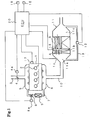
- an injector 2 (in the illustrated example, an injector of a common rail-type fuel injection system) is attached to a cylinder head of a diesel engine 1 installed in a vehicle.
- the injector 2 receives signals from an engine control unit (ECU) 20 serving as control means to control the injection timing and injection amount.
- ECU engine control unit
- An intake throttle valve 4 is provided in an intake passage 3 of the engine 1 for varying the passage cross section.
- a driving portion 4a of the intake throttle valve 4 receives signals from the ECU 20 to open/close control the intake throttle valve 4.
- An intake manifold 5 and an exhaust manifold 6 of the engine 1 are linked by an EGR passage 7.
- An EGR valve 8 is provided in the EGR passage 7 for varying the passage cross section.
- a driving portion 8a of the EGR valve 8 receives signals from the ECU 20 to open/close control the EGR valve 8.
- An EGR cooler 9 is provided in the EGR passage 7 upstream of the EGR valve 8 (on the upstream side of the EGR gas flow direction) for cooling EGR gas which passes through the passage 7.
- An oxidation catalyst A and a catalyst-carrying filter B are provided in series on an exhaust passage 10 of the engine 1.
- the oxidation catalyst A and catalyst-carrying filter B are accommodated in a storage case 11 interposed in the exhaust passage 10.
- the oxidation catalyst A is disposed on the upstream side of the exhaust gas flow, and the catalyst-carrying filter B is disposed on the downstream side of the oxidation catalyst A at a predetermined remove therefrom.
- the interior of the storage case 11 is partitioned into an upstream chamber 11a, an intermediate chamber 11b, and a downstream chamber 11c by the oxidation catalyst A and catalyst-carrying filter B.
- the oxidation catalyst A is constituted by a block body composed entirely of an oxidation catalyst substance, and a plurality of pores connecting the upstream chamber 11a to the intermediate chamber 11b are provided in this block body.
- the oxidation catalyst A rises in temperature when supplied with unburned fuel components, thereby heating the exhaust gas which flows into the downstream side catalyst-carrying filter B.
- the oxidation catalyst A functions to raise the temperature of the catalyst-carrying filter B.
- the oxidation catalyst A assists in raising the temperature of the catalyst-carrying filter B, and therefore may be omitted, as will be described hereafter.
- the catalyst-carrying filter B comprises a plurality of pores connecting the intermediate chamber 11b to the downstream chamber 11c. The upstream end and downstream end of adjacent pores are blocked alternately, and a catalyst is carried on the inner peripheral surface of each pore.
- the catalyst-carrying filter B traps the PM in the exhaust gas on the inner peripheral surface of the pores, and rises in temperature when supplied with unburned fuel components so that the trapped PM is burned. Thus the catalyst-carrying filter B regenerates.
- the differential pressure between the upstream chamber 11a and downstream chamber 11c is detected by a differential pressure sensor 12. More specifically, the upstream chamber 11a and downstream chamber 11c are connected by a pipe 13, and the differential pressure sensor 12 is provided at a point on the pipe 13 for detecting the differential pressure between the left and right of the pipe 13. The detection value of the differential pressure sensor 12 is outputted to the ECU 20.
- signals from an accelerator position sensor 16 for detecting the opening of an accelerator pedal, signals from a rotation speed sensor 17 for detecting the engine rotation speed, and signals from a distance sensor 18 for detecting the traveled distance of the vehicle are also inputted respectively into the ECU 20.
- the fixed amount of PM may become trapped in the catalyst-carrying filter B before the traveled distance of the vehicle reaches the predetermined distance.
- the differential pressure is detected by the differential pressure sensor 12 constantly or at predetermined time intervals, and when the differential pressure exceeds a predetermined differential pressure, it is estimated that the fixed amount of PM has accumulated in the catalyst-carrying filter B and determined that the catalyst-carrying filter B should be regenerated.
- the ECU 20 When it is determined that the catalyst-carrying filter B is not to be regenerated, the ECU 20 outputs a signal to the injector 2 to perform normal fuel injection on the basis of a signal from the accelerator position sensor 16 and a signal from the rotation speed sensor 17.
- regeneration is performed by switching between normal injection, multi-injection, and post-injection in the following manner in accordance with the detection values of the catalyst inlet exhaust gas temperature sensor 14 and filter inlet exhaust gas temperature sensor 15. Multi-injection and post-injection are as described in the background art section.
- a first predetermined temperature the activation temperature of the oxidation catalyst A, for example 250°C
- first a multi-injection is performed.
- waste heat that is not converted into motive power is supplied to the oxidation catalyst A, causing the temperature of the oxidation catalyst A to rise to its activation temperature.
- a post-injection is then performed, whereby exhaust gas containing unburned components is supplied to the oxidation catalyst A and catalyst-carrying filter B.
- the temperature of the exhaust gas is raised by the oxidation catalyst A to become high-temperature gas which is supplied to the catalyst-carrying filter B, and thus the temperature of the catalyst-carrying filter B is raised to its activation temperature (approximately 500 to 600°C).
- the PM trapped in the catalyst-carrying filter B is burned, and the catalyst-carrying filter B is forcibly regenerated.
- multi-injection may be performed at the same time as post-injection.
- post-injection may be performed after the detected temperature of the filter inlet exhaust gas temperature sensor 15 has reached a second predetermined temperature (approximately 300°C, for example).
- the EGR valve 8 which has been closed up to this point, is opened by the ECU 20.
- the injector 2 does not inject any fuel, and hence air (exhaust gas) that is not mixed with fuel is recirculated to the intake manifold 5 from the exhaust manifold 6 through the EGR passage 7.
- air exhaust gas
- the residual unburned components in the EGR passage 7 and EGR cooler 9 can be scavenged in an appropriate manner by the air that is not mixed with fuel.
- unburned components can be prevented from accumulating in tar form in the EGR passage 7 and EGR cooler 9.
- the intake throttle valve 4 may be controlled by the ECU 20 to close (including a fully closed state) during regeneration of the catalyst-carrying filter B.
- the intake throttle valve 4 being "fully closed” indicates that a little intake air may pass therethrough. In so doing, the amount of new intake air is reduced, and hence reductions in the temperature of the exhaust gas passing through the catalyst-carrying filter B can be suppressed. As a result, reductions in the temperature of the catalyst-carrying filter B are suppressed, and a deterioration in the regeneration capability thereof is prevented.
- the EGR valve 8 is open when no fuel is injected through the injector 2, and therefore by closing the intake throttle valve 4 and opening the EGR valve 8 when no fuel is injected during regeneration of the catalyst-carrying filter B, the residual unburned components in the EGR passage 7 and EGR cooler 9 can be scavenged by air that is not mixed with fuel.
- the present invention is not limited to the embodiment described above.
- a constitution is also possible in which the oxidation catalyst A is provided in the storage case 11 and a filter which does not carry a catalyst is provided downstream thereof. Likewise with this constitution, the temperature of the filter can be raised to a regeneration temperature by raising the temperature of the oxidation catalyst A through multi-injection and or post-injection.
Landscapes
- Engineering & Computer Science (AREA)
- Chemical & Material Sciences (AREA)
- Combustion & Propulsion (AREA)
- Mechanical Engineering (AREA)
- General Engineering & Computer Science (AREA)
- Processes For Solid Components From Exhaust (AREA)
- Exhaust Gas After Treatment (AREA)
- Exhaust-Gas Circulating Devices (AREA)
- Output Control And Ontrol Of Special Type Engine (AREA)
- Electrical Control Of Air Or Fuel Supplied To Internal-Combustion Engine (AREA)
- Control Of Throttle Valves Provided In The Intake System Or In The Exhaust System (AREA)
- Combined Controls Of Internal Combustion Engines (AREA)
- Filtering Of Dispersed Particles In Gases (AREA)
- Exhaust Gas Treatment By Means Of Catalyst (AREA)
Applications Claiming Priority (2)
| Application Number | Priority Date | Filing Date | Title |
|---|---|---|---|
| JP2004115815 | 2004-04-09 | ||
| JP2004115815A JP4196872B2 (ja) | 2004-04-09 | 2004-04-09 | エンジンの排気浄化装置 |
Publications (3)
| Publication Number | Publication Date |
|---|---|
| EP1584805A2 EP1584805A2 (en) | 2005-10-12 |
| EP1584805A3 EP1584805A3 (en) | 2006-12-06 |
| EP1584805B1 true EP1584805B1 (en) | 2015-05-06 |
Family
ID=34909551
Family Applications (1)
| Application Number | Title | Priority Date | Filing Date |
|---|---|---|---|
| EP20050007097 Ceased EP1584805B1 (en) | 2004-04-09 | 2005-03-31 | Engine exhaust gas purification device |
Country Status (4)
| Country | Link |
|---|---|
| US (1) | US7716920B2 (ja) |
| EP (1) | EP1584805B1 (ja) |
| JP (1) | JP4196872B2 (ja) |
| CN (2) | CN100572769C (ja) |
Families Citing this family (30)
| Publication number | Priority date | Publication date | Assignee | Title |
|---|---|---|---|---|
| JP3821154B1 (ja) * | 2005-03-16 | 2006-09-13 | いすゞ自動車株式会社 | 排気ガス浄化方法及び排気ガス浄化システム |
| JP4463144B2 (ja) * | 2005-05-13 | 2010-05-12 | 本田技研工業株式会社 | 内燃機関の排ガス浄化装置 |
| JP3988776B2 (ja) * | 2005-07-15 | 2007-10-10 | いすゞ自動車株式会社 | 排気ガス浄化システムの制御方法及び排気ガス浄化システム |
| JP4415963B2 (ja) * | 2006-03-17 | 2010-02-17 | トヨタ自動車株式会社 | 内燃機関の排気浄化装置 |
| FR2910058B1 (fr) * | 2006-12-14 | 2011-03-04 | Renault Sas | Procede de limitation de bruit d'admission d'air produit a la fin de la regeneration du systeme de post-traitement des gaz d'echappement |
| JP2008196445A (ja) * | 2007-02-15 | 2008-08-28 | Toyota Motor Corp | 内燃機関の制御装置 |
| JP2009138704A (ja) * | 2007-12-10 | 2009-06-25 | Mitsubishi Fuso Truck & Bus Corp | 排気後処理装置 |
| JP5024066B2 (ja) | 2008-01-16 | 2012-09-12 | 株式会社デンソー | 内燃機関の排気浄化装置 |
| JP4277933B1 (ja) * | 2008-06-11 | 2009-06-10 | トヨタ自動車株式会社 | 内燃機関装置およびその制御方法並びに車両 |
| KR101405752B1 (ko) * | 2008-07-22 | 2014-06-10 | 현대자동차주식회사 | 배기가스 재순환장치의 크리닝장치 |
| JP2010144625A (ja) * | 2008-12-18 | 2010-07-01 | Mazda Motor Corp | エンジンの排気浄化装置 |
| JP4852127B2 (ja) * | 2009-06-25 | 2012-01-11 | 日立建機株式会社 | 作業機械 |
| GB2472816B (en) * | 2009-08-19 | 2013-10-16 | Gm Global Tech Operations Inc | Method for regenerating a diesel particulate filter |
| JP5523028B2 (ja) * | 2009-09-04 | 2014-06-18 | 日立建機株式会社 | 油圧作業機械の油圧駆動装置 |
| US9416713B2 (en) * | 2010-05-07 | 2016-08-16 | Yanmar Co., Ltd. | Exhaust gas purification system |
| JP5464059B2 (ja) * | 2010-06-04 | 2014-04-09 | マツダ株式会社 | エンジンの制御方法及び制御装置 |
| DE102011006920A1 (de) * | 2011-04-07 | 2012-10-11 | Robert Bosch Gmbh | Verfahren und Vorrichtung zur Steuerung der Regeneration eines Partikelfilters |
| FR2977004A1 (fr) * | 2011-06-27 | 2012-12-28 | Cmi Thermline Services | Dispositif et procede de gestion d'imbrules pour bruleurs regeneratifs, bruleur comportant un tel dispositif |
| US20130160432A1 (en) * | 2011-09-28 | 2013-06-27 | International Engine Intellectual Property Company Llc | Limiting nox emissions |
| US20130086887A1 (en) * | 2011-10-07 | 2013-04-11 | Nathaniel D. Bergland | Method For Reducing The Rate Of Exhaust Heat Loss |
| JP5869387B2 (ja) * | 2012-03-19 | 2016-02-24 | 本田技研工業株式会社 | 内燃機関の制御装置 |
| GB2504359B (en) | 2012-07-27 | 2016-01-06 | Perkins Engines Co Ltd | Method of controlling operation of an engine having both an exhaust fluid recirculation apparatus and an exhaust fluid treatment apparatus |
| JP6597667B2 (ja) * | 2017-02-21 | 2019-10-30 | トヨタ自動車株式会社 | 内燃機関の制御装置 |
| CN107762653B (zh) * | 2017-10-10 | 2020-03-17 | 中国第一汽车股份有限公司 | 柴油机氧化催化器温度控制系统 |
| JP7159876B2 (ja) * | 2019-01-08 | 2022-10-25 | トヨタ自動車株式会社 | 内燃機関の排気浄化装置 |
| US10920695B1 (en) * | 2019-09-05 | 2021-02-16 | Ford Global Technologies, Llc | Methods and systems for regeneration of an exhaust aftertreatment device |
| JP7264111B2 (ja) * | 2020-05-19 | 2023-04-25 | トヨタ自動車株式会社 | 排気浄化装置 |
| US11840980B1 (en) * | 2022-08-04 | 2023-12-12 | International Engine Intellectual Property Company, Llc | Systems and methods for selective hydrocarbon injection |
| JP2025085210A (ja) * | 2023-11-24 | 2025-06-05 | いすゞ自動車株式会社 | 車両 |
| CN119633514B (zh) * | 2025-02-05 | 2025-08-29 | 上海湉蓓科技有限公司 | 一种化工废气处理净化设备 |
Family Cites Families (28)
| Publication number | Priority date | Publication date | Assignee | Title |
|---|---|---|---|---|
| US4345431A (en) * | 1980-03-25 | 1982-08-24 | Shimizu Construction Co. Ltd. | Exhaust gas cleaning system for diesel engines |
| JPS5786536A (en) * | 1980-11-17 | 1982-05-29 | Toyota Motor Corp | Reproduction method of particle catcher and fuel supplier for diesel engine |
| JPS5851235A (ja) | 1981-09-18 | 1983-03-25 | Toyota Motor Corp | デイ−ゼルエンジンに於ける吸気絞り弁の制御装置 |
| DE3909932A1 (de) | 1989-03-25 | 1990-09-27 | Daimler Benz Ag | Verfahren zur regeneration eines in der abgasleitung einer aufgeladenen brennkraftmaschine angeordneten partikelfilters |
| DE3912301A1 (de) * | 1989-04-14 | 1990-10-25 | Daimler Benz Ag | Verfahren zur regeneration eines in der abgasleitung einer luftverdichtenden brennkraftmaschine angeordneten russpartikelfilters |
| JP3211215B2 (ja) | 1991-07-12 | 2001-09-25 | 東亞合成株式会社 | 結晶質リン酸ジルコニウム化合物の製造方法 |
| JPH05106518A (ja) | 1991-10-16 | 1993-04-27 | Nissan Motor Co Ltd | デイーゼル機関の排気還流装置 |
| JP2582972B2 (ja) | 1991-11-12 | 1997-02-19 | 日産自動車株式会社 | ディーゼル機関の排気還流装置 |
| JP3348659B2 (ja) * | 1998-02-13 | 2002-11-20 | 三菱自動車工業株式会社 | 筒内噴射型内燃機関 |
| US6269791B1 (en) * | 1998-07-22 | 2001-08-07 | Toyota Jidosha Kabushiki Kaisha | Control system for an internal combustion engine |
| CA2375813C (en) * | 1999-05-07 | 2005-12-06 | Toyota Jidosha Kabushiki Kaisha | Exhaust gas purification device of internal combustion engine |
| JP3558022B2 (ja) * | 2000-01-11 | 2004-08-25 | トヨタ自動車株式会社 | 内燃機関の排気浄化装置 |
| DE10010031B4 (de) * | 2000-03-02 | 2011-06-09 | Volkswagen Ag | Verfahren und Vorrichtung zur Durchführung einer NOx-Regeneration eines in einem Abgaskanal einer Verbrennungskraftmaschine angeordneten NOx-Speicherkatalysators |
| DE10010032A1 (de) * | 2000-03-02 | 2001-10-25 | Volkswagen Ag | Verfahren und Vorrichtung zur Durchführung einer NO¶x¶-Regeneration eines in einem Abgaskanal einer Verbrennungskraftmaschine angeordneten NO¶x¶-Speicherkatalysators |
| DE60107765T2 (de) * | 2000-06-29 | 2005-05-12 | Toyota Jidosha K.K., Toyota | Vorrichtung zur Reinigung des Abgases einer Brennkraftmaschine |
| EP1205647B1 (de) * | 2000-11-03 | 2003-03-05 | Ford Global Technologies, Inc., A subsidiary of Ford Motor Company | Verfahren zur Regeneration des Partikelfilters eines Dieselmotors |
| DE50000400D1 (de) * | 2000-11-03 | 2002-09-26 | Ford Global Tech Inc | Regelungsanordnung und Verfahren zur Unterbrechung der Regeneration eines Partikelfilters eines Dieselmotors |
| US6598387B2 (en) * | 2000-12-21 | 2003-07-29 | Ford Global Technologies, Llc | Reduction of exhaust smoke emissions following extended diesel engine idling |
| US6497095B2 (en) * | 2000-12-21 | 2002-12-24 | Ford Global Technologies, Inc. | Regeneration of diesel engine particulate filter only above low fuel levels |
| JP4352635B2 (ja) * | 2001-06-07 | 2009-10-28 | 株式会社デンソー | 内燃機関の排気浄化装置 |
| US6536209B2 (en) * | 2001-06-26 | 2003-03-25 | Caterpillar Inc | Post injections during cold operation |
| JP3959600B2 (ja) | 2001-07-18 | 2007-08-15 | 三菱ふそうトラック・バス株式会社 | 内燃機関の排気浄化装置 |
| EP1291513B1 (en) * | 2001-09-07 | 2010-11-10 | Mitsubishi Jidosha Kogyo Kabushiki Kaisha | Exhaust emission control device of engine |
| DE10215479A1 (de) * | 2002-04-09 | 2003-10-23 | Opel Adam Ag | Verfahren zum Betreiben einer Brennkraftmaschine mit Abgasrückführung, Abgaskatalysator und Schubabschaltung |
| JP2003336549A (ja) * | 2002-05-20 | 2003-11-28 | Denso Corp | 内燃機関のegr装置 |
| JP3985053B2 (ja) * | 2002-07-15 | 2007-10-03 | マツダ株式会社 | エンジンの排気微粒子処理装置 |
| JP2004293339A (ja) * | 2003-03-25 | 2004-10-21 | Mitsubishi Fuso Truck & Bus Corp | 排ガス浄化装置 |
| JP4139259B2 (ja) * | 2003-04-08 | 2008-08-27 | 日野自動車株式会社 | パティキュレートフィルタの再生方法 |
-
2004
- 2004-04-09 JP JP2004115815A patent/JP4196872B2/ja not_active Expired - Fee Related
-
2005
- 2005-03-31 CN CNB2005100600783A patent/CN100572769C/zh not_active Expired - Fee Related
- 2005-03-31 EP EP20050007097 patent/EP1584805B1/en not_active Ceased
- 2005-03-31 CN CN2008101821768A patent/CN101408120B/zh not_active Expired - Fee Related
- 2005-04-05 US US11/099,029 patent/US7716920B2/en not_active Expired - Fee Related
Also Published As
| Publication number | Publication date |
|---|---|
| JP2005299480A (ja) | 2005-10-27 |
| US20050223697A1 (en) | 2005-10-13 |
| CN100572769C (zh) | 2009-12-23 |
| CN101408120B (zh) | 2012-06-13 |
| EP1584805A2 (en) | 2005-10-12 |
| CN101408120A (zh) | 2009-04-15 |
| US7716920B2 (en) | 2010-05-18 |
| EP1584805A3 (en) | 2006-12-06 |
| JP4196872B2 (ja) | 2008-12-17 |
| CN1680690A (zh) | 2005-10-12 |
Similar Documents
| Publication | Publication Date | Title |
|---|---|---|
| EP1584805B1 (en) | Engine exhaust gas purification device | |
| EP2581570B1 (en) | Exhaust gas purification system | |
| EP2116698A1 (en) | Control method of exhaust emission purification system and exhaust emission purification system | |
| WO2007026809A1 (ja) | パティキュレートフィルタの再生方法 | |
| US8549843B2 (en) | Method of controlling exhaust gas purification system and exhaust gas purification system | |
| CN102939441B (zh) | 废气净化系统 | |
| WO2012157265A1 (ja) | パティキュレートフィルタの手動再生方法 | |
| JP4379314B2 (ja) | 内燃機関の排気浄化装置 | |
| JP4383983B2 (ja) | ブローバイガス還流装置 | |
| WO2007004471A1 (ja) | ディーゼルエンジンの制御装置 | |
| JP4012043B2 (ja) | パティキュレートフィルタの再生方法 | |
| US20190264591A1 (en) | Regeneration control device for exhaust purification device | |
| JP4412049B2 (ja) | ディーゼルエンジンの排気ガス後処理装置 | |
| EP1867846B1 (en) | DPF regeneration system of internal combustion engine | |
| WO2011155584A1 (ja) | 排気管噴射制御装置 | |
| JP5478276B2 (ja) | パティキュレートフィルタの再生方法 | |
| KR102131704B1 (ko) | Dpf 역세를 위한 공기 역순환 장치 및 이를 이용한 dpf 역세 방법 | |
| JP4735505B2 (ja) | ターボ過給機付きエンジンのサージ防止制御装置及びサージ防止制御方法 | |
| JP2003155915A (ja) | 排気浄化装置 | |
| JP2005036726A (ja) | 内燃機関の排気昇温装置 | |
| JP2006274979A (ja) | 排気浄化装置 | |
| JP2005163652A (ja) | 排気浄化装置 | |
| JP5487723B2 (ja) | パティキュレートフィルタの再生方法 | |
| JP4261325B2 (ja) | 排気浄化装置 | |
| JP2005155534A (ja) | 内燃機関の排気昇温装置 |
Legal Events
| Date | Code | Title | Description |
|---|---|---|---|
| PUAI | Public reference made under article 153(3) epc to a published international application that has entered the european phase |
Free format text: ORIGINAL CODE: 0009012 |
|
| AK | Designated contracting states |
Kind code of ref document: A2 Designated state(s): AT BE BG CH CY CZ DE DK EE ES FI FR GB GR HU IE IS IT LI LT LU MC NL PL PT RO SE SI SK TR |
|
| AX | Request for extension of the european patent |
Extension state: AL BA HR LV MK YU |
|
| PUAL | Search report despatched |
Free format text: ORIGINAL CODE: 0009013 |
|
| AK | Designated contracting states |
Kind code of ref document: A3 Designated state(s): AT BE BG CH CY CZ DE DK EE ES FI FR GB GR HU IE IS IT LI LT LU MC NL PL PT RO SE SI SK TR |
|
| AX | Request for extension of the european patent |
Extension state: AL BA HR LV MK YU |
|
| 17P | Request for examination filed |
Effective date: 20070424 |
|
| AKX | Designation fees paid |
Designated state(s): DE FR GB IT |
|
| 17Q | First examination report despatched |
Effective date: 20090416 |
|
| GRAP | Despatch of communication of intention to grant a patent |
Free format text: ORIGINAL CODE: EPIDOSNIGR1 |
|
| INTG | Intention to grant announced |
Effective date: 20141009 |
|
| GRAS | Grant fee paid |
Free format text: ORIGINAL CODE: EPIDOSNIGR3 |
|
| GRAA | (expected) grant |
Free format text: ORIGINAL CODE: 0009210 |
|
| AK | Designated contracting states |
Kind code of ref document: B1 Designated state(s): DE FR GB IT |
|
| REG | Reference to a national code |
Ref country code: GB Ref legal event code: FG4D |
|
| REG | Reference to a national code |
Ref country code: DE Ref legal event code: R096 Ref document number: 602005046479 Country of ref document: DE Effective date: 20150618 |
|
| REG | Reference to a national code |
Ref country code: DE Ref legal event code: R097 Ref document number: 602005046479 Country of ref document: DE |
|
| PLBE | No opposition filed within time limit |
Free format text: ORIGINAL CODE: 0009261 |
|
| STAA | Information on the status of an ep patent application or granted ep patent |
Free format text: STATUS: NO OPPOSITION FILED WITHIN TIME LIMIT |
|
| 26N | No opposition filed |
Effective date: 20160209 |
|
| REG | Reference to a national code |
Ref country code: FR Ref legal event code: PLFP Year of fee payment: 12 |
|
| PG25 | Lapsed in a contracting state [announced via postgrant information from national office to epo] |
Ref country code: IT Free format text: LAPSE BECAUSE OF FAILURE TO SUBMIT A TRANSLATION OF THE DESCRIPTION OR TO PAY THE FEE WITHIN THE PRESCRIBED TIME-LIMIT Effective date: 20150506 |
|
| REG | Reference to a national code |
Ref country code: FR Ref legal event code: PLFP Year of fee payment: 13 |
|
| PGFP | Annual fee paid to national office [announced via postgrant information from national office to epo] |
Ref country code: FR Payment date: 20170213 Year of fee payment: 13 |
|
| PGFP | Annual fee paid to national office [announced via postgrant information from national office to epo] |
Ref country code: GB Payment date: 20170329 Year of fee payment: 13 |
|
| PGFP | Annual fee paid to national office [announced via postgrant information from national office to epo] |
Ref country code: DE Payment date: 20170329 Year of fee payment: 13 |
|
| REG | Reference to a national code |
Ref country code: DE Ref legal event code: R119 Ref document number: 602005046479 Country of ref document: DE |
|
| GBPC | Gb: european patent ceased through non-payment of renewal fee |
Effective date: 20180331 |
|
| PG25 | Lapsed in a contracting state [announced via postgrant information from national office to epo] |
Ref country code: DE Free format text: LAPSE BECAUSE OF NON-PAYMENT OF DUE FEES Effective date: 20181002 |
|
| PG25 | Lapsed in a contracting state [announced via postgrant information from national office to epo] |
Ref country code: GB Free format text: LAPSE BECAUSE OF NON-PAYMENT OF DUE FEES Effective date: 20180331 |
|
| PG25 | Lapsed in a contracting state [announced via postgrant information from national office to epo] |
Ref country code: FR Free format text: LAPSE BECAUSE OF NON-PAYMENT OF DUE FEES Effective date: 20180331 |