EP1584802B1 - Control method for an exhaust gas purification system and an exhaust gas purification system - Google Patents
Control method for an exhaust gas purification system and an exhaust gas purification system Download PDFInfo
- Publication number
- EP1584802B1 EP1584802B1 EP05102142.6A EP05102142A EP1584802B1 EP 1584802 B1 EP1584802 B1 EP 1584802B1 EP 05102142 A EP05102142 A EP 05102142A EP 1584802 B1 EP1584802 B1 EP 1584802B1
- Authority
- EP
- European Patent Office
- Prior art keywords
- regeneration
- exhaust gas
- collecting quantity
- vehicle
- control
- Prior art date
- Legal status (The legal status is an assumption and is not a legal conclusion. Google has not performed a legal analysis and makes no representation as to the accuracy of the status listed.)
- Ceased
Links
Images
Classifications
-
- F—MECHANICAL ENGINEERING; LIGHTING; HEATING; WEAPONS; BLASTING
- F02—COMBUSTION ENGINES; HOT-GAS OR COMBUSTION-PRODUCT ENGINE PLANTS
- F02D—CONTROLLING COMBUSTION ENGINES
- F02D41/00—Electrical control of supply of combustible mixture or its constituents
- F02D41/02—Circuit arrangements for generating control signals
- F02D41/021—Introducing corrections for particular conditions exterior to the engine
- F02D41/0235—Introducing corrections for particular conditions exterior to the engine in relation with the state of the exhaust gas treating apparatus
- F02D41/027—Introducing corrections for particular conditions exterior to the engine in relation with the state of the exhaust gas treating apparatus to purge or regenerate the exhaust gas treating apparatus
- F02D41/029—Introducing corrections for particular conditions exterior to the engine in relation with the state of the exhaust gas treating apparatus to purge or regenerate the exhaust gas treating apparatus the exhaust gas treating apparatus being a particulate filter
-
- F—MECHANICAL ENGINEERING; LIGHTING; HEATING; WEAPONS; BLASTING
- F01—MACHINES OR ENGINES IN GENERAL; ENGINE PLANTS IN GENERAL; STEAM ENGINES
- F01N—GAS-FLOW SILENCERS OR EXHAUST APPARATUS FOR MACHINES OR ENGINES IN GENERAL; GAS-FLOW SILENCERS OR EXHAUST APPARATUS FOR INTERNAL-COMBUSTION ENGINES
- F01N3/00—Exhaust or silencing apparatus having means for purifying, rendering innocuous, or otherwise treating exhaust
- F01N3/02—Exhaust or silencing apparatus having means for purifying, rendering innocuous, or otherwise treating exhaust for cooling, or for removing solid constituents of, exhaust
- F01N3/021—Exhaust or silencing apparatus having means for purifying, rendering innocuous, or otherwise treating exhaust for cooling, or for removing solid constituents of, exhaust by means of filters
- F01N3/023—Exhaust or silencing apparatus having means for purifying, rendering innocuous, or otherwise treating exhaust for cooling, or for removing solid constituents of, exhaust by means of filters using means for regenerating the filters, e.g. by burning trapped particles
- F01N3/0231—Exhaust or silencing apparatus having means for purifying, rendering innocuous, or otherwise treating exhaust for cooling, or for removing solid constituents of, exhaust by means of filters using means for regenerating the filters, e.g. by burning trapped particles using special exhaust apparatus upstream of the filter for producing nitrogen dioxide, e.g. for continuous filter regeneration systems [CRT]
-
- F—MECHANICAL ENGINEERING; LIGHTING; HEATING; WEAPONS; BLASTING
- F02—COMBUSTION ENGINES; HOT-GAS OR COMBUSTION-PRODUCT ENGINE PLANTS
- F02D—CONTROLLING COMBUSTION ENGINES
- F02D41/00—Electrical control of supply of combustible mixture or its constituents
- F02D41/30—Controlling fuel injection
- F02D41/38—Controlling fuel injection of the high pressure type
- F02D41/40—Controlling fuel injection of the high pressure type with means for controlling injection timing or duration
- F02D41/402—Multiple injections
- F02D41/405—Multiple injections with post injections
-
- F—MECHANICAL ENGINEERING; LIGHTING; HEATING; WEAPONS; BLASTING
- F02—COMBUSTION ENGINES; HOT-GAS OR COMBUSTION-PRODUCT ENGINE PLANTS
- F02D—CONTROLLING COMBUSTION ENGINES
- F02D41/00—Electrical control of supply of combustible mixture or its constituents
- F02D41/22—Safety or indicating devices for abnormal conditions
- F02D2041/228—Warning displays
-
- F—MECHANICAL ENGINEERING; LIGHTING; HEATING; WEAPONS; BLASTING
- F02—COMBUSTION ENGINES; HOT-GAS OR COMBUSTION-PRODUCT ENGINE PLANTS
- F02D—CONTROLLING COMBUSTION ENGINES
- F02D2200/00—Input parameters for engine control
- F02D2200/02—Input parameters for engine control the parameters being related to the engine
- F02D2200/08—Exhaust gas treatment apparatus parameters
- F02D2200/0812—Particle filter loading
-
- F—MECHANICAL ENGINEERING; LIGHTING; HEATING; WEAPONS; BLASTING
- F02—COMBUSTION ENGINES; HOT-GAS OR COMBUSTION-PRODUCT ENGINE PLANTS
- F02D—CONTROLLING COMBUSTION ENGINES
- F02D2250/00—Engine control related to specific problems or objectives
- F02D2250/11—Oil dilution, i.e. prevention thereof or special controls according thereto
-
- F—MECHANICAL ENGINEERING; LIGHTING; HEATING; WEAPONS; BLASTING
- F02—COMBUSTION ENGINES; HOT-GAS OR COMBUSTION-PRODUCT ENGINE PLANTS
- F02D—CONTROLLING COMBUSTION ENGINES
- F02D41/00—Electrical control of supply of combustible mixture or its constituents
- F02D41/02—Circuit arrangements for generating control signals
- F02D41/021—Introducing corrections for particular conditions exterior to the engine
-
- Y—GENERAL TAGGING OF NEW TECHNOLOGICAL DEVELOPMENTS; GENERAL TAGGING OF CROSS-SECTIONAL TECHNOLOGIES SPANNING OVER SEVERAL SECTIONS OF THE IPC; TECHNICAL SUBJECTS COVERED BY FORMER USPC CROSS-REFERENCE ART COLLECTIONS [XRACs] AND DIGESTS
- Y02—TECHNOLOGIES OR APPLICATIONS FOR MITIGATION OR ADAPTATION AGAINST CLIMATE CHANGE
- Y02T—CLIMATE CHANGE MITIGATION TECHNOLOGIES RELATED TO TRANSPORTATION
- Y02T10/00—Road transport of goods or passengers
- Y02T10/10—Internal combustion engine [ICE] based vehicles
- Y02T10/40—Engine management systems
Definitions
- the present invention relates to an exhaust gas purification system that purifies particulate matters from the exhaust gas discharged by diesel and other internal combustion engines using a continuous regeneration type diesel particulate filter device and also to a control method thereof.
- PM particulate matters
- DPFs for collecting this PM include a monolithic honeycomb form wall flow type filter made of ceramic, a fiber form type filter made of fiber shape ceramic or metal, and so on.
- An exhaust gas purification system using these DPFs are installed on the way of the exhaust passage of an internal combustion engine, similarly to the other exhaust gas purification systems, for cleaning exhaust gas generated in the internal combustion engine before discharging the same.
- DPF devices include a continuous regeneration type DPF device as in EP 1 321 642 A1 wherein an oxidation catalyst is installed upstream of the DPF, a continuous regeneration type DPF device wherein the PM combustion temperature is lowered by the effect of a catalyst supported on a filter with catalyst and PM is burned by the exhaust gas, etc.
- the continuous regeneration type DPF device wherein the oxidation catalyst is installed upstream of the DPF uses the fact that the oxidation of PM by NO 2 (nitrogen dioxide) is executed at a lower temperature than the temperature at which PM is oxidized with oxygen in the exhaust gas.
- This continuous regeneration type DPF device is composed of an oxidation catalyst and a filter. NO (nitrogen monoxide) in the exhaust gas is oxidized to NO 2 , by an oxidation catalyst supporting platinum or the like on the upstream side. PM collected by the filter on the downstream side is oxidized by this NO 2 to CO 2 (carbon dioxide). Thereby, PM is removed.
- the continuous regeneration type DPF device of filter with catalyst is composed of a filter with catalyst such as cerium oxide (CeO 2 ).
- PM is oxidized by a reaction (4CeO 2 +C ⁇ 2Ce 2 O 3 + CO 2 , 2Ce 2 O 3 + O 2 ⁇ 4CeO 2 , etc.) using O 2 (oxygen) in the exhaust gas by means of the filter with catalyst, within the low temperature range (on the order of 300°C to 600°C).
- PM is oxidized by O 2 (oxygen) in the exhaust gas, within the high temperature range (equal or higher than the order of 600°C) which is higher than the temperature where PM is burned with O 2 in the exhaust gas.
- the oxidation catalyst is also installed on the upstream side and oxidation and removal of PM is stimulated by raising exhaust gas temperature through oxidation reaction of unburned HC and CO in the exhaust gas. At the same time, the emission of unburned HC and CO into the atmosphere is prevented.
- this filter clogging As a measure against this filter clogging, it has been conceived to forcibly burn and remove the collected PM by forcibly raising the exhaust gas temperature, when the amount of clogging has exceeded a predetermined amount.
- means for detecting such filter clogging there are some methods such as a method for detecting by the differential pressure before and after the filter, and a method for detecting through determination of the PM accumulation quantity by calculating in accordance of a map data in which the collecting quantity of PM to be collected is previously set based on the engine operation state.
- means for exhaust gas temperature raising there is a method by injection control of the fuel injection into a cylinder, or a method by fuel control in the direct fuel injection in the exhaust pipe.
- the following exhaust gas purification device for internal combustion engine is disclosed in Japanese patent application Kokai publication No. 2003-120390 .
- This device judges the period from a subordinate injection date and time of unburned fuel of previous time up to the subordinate injection date and time of this time. When this period is longer than a predetermined period required for all unburned fuel diluted in lubricant to evaporate, a large retardation value of subordinate injection is taken to increase the unburned fuel to be added to a catalyst. When the former period is shorter than the latter period, dilution is not performed.
- a method is considered in which a filter is regenerated by using a lamp etc. and thereby notifying a driver that forced regeneration is necessary when a filter is clogged at a predetermined value and the driver receiving the notification stops a vehicle and then operates a manual regeneration switch at the driver seat to perform the forced regeneration control.
- an exhaust gas purification system in an internal combustion engine mounted on a vehicle provided with a continuous regeneration type diesel particulate filter device in the exhaust passage thereof: having a diesel particulate filter control means including; a collecting quantity detection means for detecting the collecting quantity of particulate matters ( ⁇ Pm) in the continuous regeneration type diesel particulate filter device; a travel distance detection means for detecting the travel distance (Lm) of the vehicle; a forced regeneration control means for performing a post injection in a fuel injection into a cylinder to raise an exhaust gas temperature and forcibly burning the collected matters, and thereby regenerating the continuous regeneration type diesel particulate filter device, and for performing a forced regeneration which consists of an automatic travelling regeneration during travelling and a manual regeneration when vehicle is stopped; and a number-of-regeneration times detection means for counting the number of regeneration (Na, Nm) by the forced regeneration control means; characterized in that, when the collecting quantity of particulate matters ( ⁇ Pm) detected by the collecting quantity detection means exceeds the predetermined judgment collecting quantity ( ⁇ P
- an oil diluted state is judged.
- automatic traveling regeneration is performed while traveling a vehicle in which diluted fuel quantity increases when the degree of oil dilution is low.
- the diluted fuel quantity is controller so that it is kept within a constant value.
- the number of regeneration times of DPF is a coefficient based on the number of regeneration times Na of automatic regeneration the number of regeneration times Nm of manual regeneration, and travel distance Lm and serves as an index of the number of regeneration times to the travel distance.
- continuous regeneration type DPF device in the above exhaust gas purification system, there are a continuous regeneration type DPF device making a filter support an oxidation catalyst, a continuous regeneration type DPF device in which an oxidation catalyst is set on the upstream side of a filter, and a continuous regeneration type DPF device in which a catalyst is supported on a filter and an oxidation catalyst is set on the upstream side of the filter.
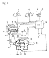
- Fig. 1 shows the configuration of an exhaust gas purification system 1 for an internal combustion engine according to an embodiment of the present invention.
- This exhaust gas purification system 1 is configured to provide a continuous regeneration DPF device 13 on an exhaust passage 12 connected to an exhaust manifold 11 of a diesel engine 10.
- This continuous regeneration DPF device 13 is configured with an oxidation catalyst 13a on the upstream side thereof and a filter with catalyst 13b on the downstream side thereof.
- the oxidation catalyst 13a is formed so as to support an oxidation catalyst of platinum (Pt) etc. on a support with a ceramic honeycomb structure etc.
- the filter with catalyst 13b is formed of a monolithic honeycomb type, wall flow type filter with entrances and exits to channels in a porous ceramic honeycomb alternately closed or a felt-type filter with randomly layered alumina other inorganic fibers or the like.
- a platinum or cerium oxide etc. catalyst is supported on this filter portion.
- a pressure difference sensor 21 is provided on the conduit tube in front of and behind the continuous regeneration DPF device 13 in order to estimate the collecting quantity of PM on the filter with catalyst 13b.
- an oxidation catalyst inlet exhaust gas temperature sensor 22 is provided upstream of the oxidation catalyst 13a and a filter inlet exhaust gas temperature sensor 23 is provided between the oxidation catalyst 13a and the filter with catalyst 13b.
- the output values from these sensors are input to an engine control unit (ECU) 30.
- the engine control unit 30 In addition to controlling the overall operation of the engine 10, the engine control unit 30 also performs regeneration control of the operation of the continuous regeneration DPF device 13.
- the fuel injection devices (i.e., injection nozzles) 14 of the engine 10 and, wherever necessary, the intake throttle valve (not shown) adjusting the intake quantity of the intake manifold 15 and the EGR valve for adjusting the EGR volume are controlled in accordance with the control signals output from this engine control unit 30.
- the EGR valve is provided together with the EGR cooler on the EGR passage (not shown).
- These fuel injection devices 14 are connected to a common-rail fuel injection system (not shown) storing temporarily the fuel pressurized to high pressure by the fuel pump (not shown).
- the accelerator opening from the accelerator position sensor (APS) 31 and the engine speed from the engine speed sensor 32 etc. are input into the engine control unit 30 together with other data such as the vehicle speed and cooling water temperature, etc.
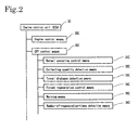
- the engine control unit 30 comprises an engine control means 20C controlling driving of the engine and a DPF control means 30C for the exhaust gas purification system 1 etc.
- the DPF control means 30C comprises a normal operating control means 31C, a collecting quantity detection means 32C, a travel distance detection means 33C, a forced regeneration control means 34C, a warning means 35C, a number-of-regeneration-times detection means 36C, etc.
- the normal operating control means 31C is in particular a means for performing normal operation unrelated to regeneration of the continuous regeneration DPF device 13.
- normal injection control is carried out wherein a predetermined volume of fuel is injected from the fuel injection devices 14 in accordance with an electric current time signal calculated in the engine control unit 30 based on signals from the accelerator position sensor 31 and signals from the engine speed sensor 32.
- the collecting quantity detection means 32C is a means for detecting the collecting quantity ⁇ Pm accumulated in the filter with catalyst 13b of the continuous regeneration DPF device 13. Detection of this collecting quantity ⁇ Pm is carried out using the cumulative calculated value of the collecting quantity estimated from the engine speed and load, the engine rotating accumulated time, and the differential pressure before and after the continuous regeneration DPF device 13 etc. In this embodiment, detection thereof is carried out based on the differential pressure before and after the continuous regeneration DPF device 13 - that is, the measurement values from the differential pressure sensor 21.
- the travel distance detection means 33C is means for detecting the distance Lm in which a vehicle travels.
- the forced regeneration control means 34C performs multi injection (multistage injection) in the fuel injection into a cylinder of the engine 10 though slightly different in control depending on the type of the continuous regeneration type DPF device 13 to raise an exhaust gas temperature up to the active temperature of the oxidation catalyst 13a. Thereafter, post injection (posterior injection) is performed to raise the entrance exhaust gas temperature of a filter to be detected by a filter entrance exhaust gas temperature sensor 23 so that a temperature and environment suitable for oxidation removal of PM are realized. Thereby, the PM collected by the filter with catalyst 13b is forcibly burned and removed to forcibly regenerate the filter with catalyst 13b. Intake-system control such as intake throttling or EGR may be used together.
- the warning means 35C is constituted of a repeater indicator (DPF lamp) 41, an alarm lamp (warning lamp) 42, etc.
- the warning means 35C is means for warning a driver so as to prompt the operation of the forced regeneration control means 34C through flashing of the repeater indicator 41 or prompting a driver to bring a vehicle to a service center through turning-on of the alarm lamp 42.
- a driver warned by the flashing of the repeater indicator 41 can actuate the forced regeneration control means 34C by operating the manual regeneration switch 43.
- the number-of-regeneration-times detection means 36C is means for counting the numbers of regeneration times Na and Nm by the forced regeneration control means 34C, which counts the numbers of regeneration times of automatic traveling regeneration and manual regeneration.
- the DPF control means 30C having these means continues the normal operation by the normal operating control means 31C in accordance with the collecting quantity ⁇ Pm of PM detected by the collecting quantity detection means 32C, warns a driver to prompt the manual operation of the forced regeneration control means 34C, or automatically operates the forced regeneration control means 34C during vehicle traveling.
- the number-of-regeneration-times coefficient Rc serving as an index for the number of regeneration times to a travel distance is compared with a predetermined judgment coefficient value R0 by using the travel distance Lm detected by the travel distance detection means 33C and the numbers of regeneration times Na and Nm detected by the number-of-regeneration-times detection means 36C. Then, when the number-of-regeneration-times coefficient Rc is smaller than the predetermined judgment coefficient value R0, automatic traveling regeneration is performed. When the number-of-regeneration-times coefficient Rc is equal to or larger than the predetermined judgment coefficient value R0, a driver is warned to prompt the operation of the forced regeneration control means 34C.
- the vehicle travel distance Lm and the numbers of regeneration times Na and Nm of DPF are counted and when a request for forced regeneration of DPF is generated, it is judged by the number-of-regeneration-times coefficient Rc serving as an index of the number of regeneration times to the travel distance whether they are kept in a dilution allowance.
- the number-of-regeneration-times coefficient Rc serving as an index of the number of regeneration times to the travel distance whether they are kept in a dilution allowance.
- automatic traveling regeneration is performed when they are kept in the dilution allowance, automatic traveling regeneration is performed and when they exceed the dilution allowance, manual regeneration is performed. Thereby, proper regeneration control is selected.
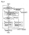
- step S11 When the control flow is called from the flow of main engine control and started, the collecting quantity ⁇ Pm of PM is checked in step S11. That is, whether regeneration control is necessary is judged in accordance with whether the detected collecting quantity ⁇ Pm is larger than a predetermined judgment collecting quantity ⁇ Pm0.
- step S20 the normal operating control by the normal operating control means 31C is performed for a predetermined control time relating to the internal of checking of the collecting quantity ⁇ Pm and the operation returns to step 511.
- the number-of-regeneration-times coefficient Rc serving as an index of the number of regeneration times to a travel distance is calculated in step S12.
- a, b, and c in the above expression are constants decided by a purposed engine and they are values previously set in accordance with such an experiment previously performed.
- step S13 the number-of-regeneration-times coefficient Rc is checked. This checking is performed in accordance with whether the number-of-regeneration-times coefficient Rc is smaller than the predetermined judgment coefficient value (fuel dilution allowance) R0.
- the predetermined judgment coefficient value fuel dilution allowance
- step S14 the automatic traveling regeneration is carried out until the regeneration of DPF is completed.
- step S15 the number-of-automatic traveling regeneration times Na is counted and the operation is returned to step S11.
- the accumulated calculated value of the PM is also reset in step S15.
- the automatic traveling regeneration facilitates to reduce the load due to manual forced regeneration by a driver, that is, on on/off operation of the manual regeneration switch 43.
- step S13 when the number-of-regeneration-times coefficient Rc is the predetermined judgment coefficient value R0 or more through the judgment in step S13, the driver is warned to prompt the operation of the forced regeneration control means 34C in step S16. That is, automatic traveling regeneration is inhibited in order to avoid the problem of oil dilution at the time of forced regeneration and the repeater indicator (DPF lamp) 41 is flashed.
- the driver stops the vehicle in accordance with the warning and turns on the manual regeneration switch. Thereby, manual regeneration is started and continued until regeneration of DPF is completed.
- step S17 the number of manual regeneration times Nm is counted and the operation returns to step S11.
- the accumulated calculated value of the PM is also reset in step S17.
- steps S11 to S20, steps S11 to S15, or steps S11 to S17 are repeated. Then, the vehicle is driven while repeating normal operating control and forced regeneration control. Then, when the engine key is turned off, an interruption occurs, the end operation of the DPF control in step S30 is started, and the operation is returned. Then, the operation is completed together with the end of main engine control.
- the number-of-regeneration-times coefficient Rc is compared with the predetermined judgment coefficient value R0.
- the number-of-regeneration-times coefficient Rc is smaller than the predetermined judgment coefficient value R0, it is possible to perform automatic traveling regeneration.
- the number-of-regeneration-times coefficient Rc is equal to or more than the predetermined judgment coefficient value R0, it is possible to warn the driver to prompt the actuation of the forced regeneration control means 34C.
- automatic traveling regeneration is normally selected but manual regeneration is selected only when the manual regeneration is necessary for dilution of oil. Therefore, it is possible to greatly decrease the frequency of manual regeneration by operating a manual regeneration switch and improve the operability for a user.
- the above explanation deals with the example of a continuous regeneration type DPF device in the exhaust gas purification system realized as a continuous regeneration type DPF device providing an oxidation catalyst on the upstream side of the filter while also making a catalyst supported on the filter; however, the present invention is not restricted to this embodiment. Furthermore, the continuous regeneration type DPF device may also be of the type making an oxidation catalyst supported on the filter or providing an oxidation catalyst on the upstream side of the filter, etc.
Landscapes
- Engineering & Computer Science (AREA)
- Chemical & Material Sciences (AREA)
- Combustion & Propulsion (AREA)
- Mechanical Engineering (AREA)
- General Engineering & Computer Science (AREA)
- Processes For Solid Components From Exhaust (AREA)
- Filtering Of Dispersed Particles In Gases (AREA)
- Electrical Control Of Air Or Fuel Supplied To Internal-Combustion Engine (AREA)
- Combined Controls Of Internal Combustion Engines (AREA)
- Exhaust Gas Treatment By Means Of Catalyst (AREA)
- Exhaust Gas After Treatment (AREA)
Applications Claiming Priority (2)
| Application Number | Priority Date | Filing Date | Title |
|---|---|---|---|
| JP2004113919A JP4148178B2 (ja) | 2004-04-08 | 2004-04-08 | 排気ガス浄化システムの制御方法及び排気ガス浄化システム |
| JP2004113919 | 2004-04-08 |
Publications (3)
| Publication Number | Publication Date |
|---|---|
| EP1584802A2 EP1584802A2 (en) | 2005-10-12 |
| EP1584802A3 EP1584802A3 (en) | 2007-05-09 |
| EP1584802B1 true EP1584802B1 (en) | 2013-05-08 |
Family
ID=34909519
Family Applications (1)
| Application Number | Title | Priority Date | Filing Date |
|---|---|---|---|
| EP05102142.6A Ceased EP1584802B1 (en) | 2004-04-08 | 2005-03-18 | Control method for an exhaust gas purification system and an exhaust gas purification system |
Country Status (4)
| Country | Link |
|---|---|
| US (1) | US7421837B2 (ja) |
| EP (1) | EP1584802B1 (ja) |
| JP (1) | JP4148178B2 (ja) |
| CN (1) | CN100549373C (ja) |
Families Citing this family (42)
| Publication number | Priority date | Publication date | Assignee | Title |
|---|---|---|---|---|
| JP2007002689A (ja) * | 2005-06-21 | 2007-01-11 | Honda Motor Co Ltd | 内燃機関の制御装置 |
| JP3956992B1 (ja) * | 2006-01-27 | 2007-08-08 | いすゞ自動車株式会社 | 排気ガス浄化方法及び排気ガス浄化システム |
| JP4294662B2 (ja) * | 2006-08-07 | 2009-07-15 | 本田技研工業株式会社 | 内燃機関の排ガス浄化装置 |
| JP4312225B2 (ja) | 2006-11-09 | 2009-08-12 | トヨタ自動車株式会社 | 車載ディーゼルエンジン |
| US7793492B2 (en) * | 2007-02-27 | 2010-09-14 | International Truck Intellectual Property Company, Llc | Diesel engine exhaust after-treatment operator interface algorithm |
| JP2008297969A (ja) * | 2007-05-31 | 2008-12-11 | Denso Corp | 内燃機関の排気浄化装置 |
| US7657364B2 (en) * | 2007-10-10 | 2010-02-02 | Cummins IP. Inc | Apparatus, system, and method for thermal management of an engine comprising a continuously variable transmission |
| US7980067B2 (en) * | 2007-12-20 | 2011-07-19 | Detroit Diesel Corporation | Method to operate vehicle with internal combustion engine and exhaust aftertreatment system according to detected drive cycles |
| US8091345B2 (en) * | 2008-02-06 | 2012-01-10 | Cummins Ip, Inc | Apparatus, system, and method for efficiently increasing exhaust flow temperature for an internal combustion engine |
| US8156730B2 (en) * | 2008-04-29 | 2012-04-17 | Cummins, Inc. | Engine performance management during a diesel particulate filter regeneration event |
| KR20090124222A (ko) * | 2008-05-29 | 2009-12-03 | 현대자동차주식회사 | 디젤 차량의 후처리 장치 및 재생방법 |
| US8302385B2 (en) * | 2008-05-30 | 2012-11-06 | Cummins Ip, Inc. | Apparatus, system, and method for controlling engine exhaust temperature |
| US8061129B2 (en) * | 2009-01-30 | 2011-11-22 | Thermo King Corporation and Donaldson Company, Inc. | System and method to regenerate a diesel particulate filter |
| US8240133B2 (en) * | 2009-03-31 | 2012-08-14 | GM Global Technology Operations LLC | Injector tip cleaning systems and methods |
| JP5281488B2 (ja) * | 2009-06-08 | 2013-09-04 | ヤンマー株式会社 | ディーゼルエンジン |
| US8350682B2 (en) * | 2009-06-12 | 2013-01-08 | Mack Trucks, Inc. | DPF warning system |
| JP5206644B2 (ja) | 2009-10-22 | 2013-06-12 | 株式会社豊田自動織機 | ディーゼルエンジンの排気ガス浄化装置 |
| US20110225969A1 (en) * | 2010-03-19 | 2011-09-22 | Gm Global Technology Operations, Inc. | Compressor bypass to exhaust for particulate trap regeneration |
| JP5625476B2 (ja) * | 2010-05-17 | 2014-11-19 | いすゞ自動車株式会社 | Dpfシステム |
| JP5440384B2 (ja) * | 2010-05-25 | 2014-03-12 | いすゞ自動車株式会社 | 排ガス浄化システム |
| JP2011247129A (ja) * | 2010-05-25 | 2011-12-08 | Isuzu Motors Ltd | 排気ガス浄化システム |
| JP5931328B2 (ja) * | 2010-09-28 | 2016-06-08 | 三菱重工業株式会社 | エンジンの排ガス浄化装置および浄化方法 |
| JP5736759B2 (ja) * | 2010-12-15 | 2015-06-17 | トヨタ自動車株式会社 | 内燃機関の排気浄化装置 |
| US9080494B2 (en) * | 2011-06-07 | 2015-07-14 | GM Global Technology Operations LLC | Particulate filter monitoring methods and systems |
| CN102383905B (zh) * | 2011-11-08 | 2012-12-26 | 上海三一重机有限公司 | 一种工程机械用发动机后处理再生的智能控制方法 |
| EP2607672B1 (en) * | 2011-12-20 | 2016-08-17 | Fiat Powertrain Technologies S.p.A. | System and method for regenerating the particulate filter of a Diesel engine |
| US9790852B2 (en) | 2013-06-12 | 2017-10-17 | Toyota Jidosha Kabushiki Kaisha | Condensed water treatment device for internal combustion engine |
| CN105308304B (zh) * | 2013-06-28 | 2017-03-01 | 丰田自动车株式会社 | 内燃机的凝结水处理装置 |
| KR20160009676A (ko) * | 2013-06-28 | 2016-01-26 | 얀마 가부시키가이샤 | 배기 가스 정화 장치 |
| CN103511043B (zh) * | 2013-09-22 | 2015-10-07 | 潍柴动力股份有限公司 | 一种颗粒物捕集器的主动再生控制方法及装置 |
| CN103696839B (zh) * | 2013-12-10 | 2016-04-06 | 潍柴动力股份有限公司 | Dpf主动再生系统的检测方法和装置 |
| CN105971747B (zh) * | 2016-06-27 | 2021-02-19 | 南京依维柯汽车有限公司 | 一种dpf驾驶员手动再生方法 |
| CN107339137A (zh) * | 2016-12-16 | 2017-11-10 | 安徽江淮汽车集团股份有限公司 | 一种dpf主动再生的控制方法及系统 |
| BR202017013993U2 (pt) * | 2017-06-28 | 2019-01-15 | William Luiz De Lima | dispositivo eletrônico de alerta para veículos |
| CN109838296B (zh) * | 2017-11-29 | 2021-09-28 | 上海汽车集团股份有限公司 | 具有驾驶者引导功能的颗粒过滤器再生管理方法和系统 |
| KR102053336B1 (ko) * | 2018-10-18 | 2019-12-06 | 현대오트론 주식회사 | Dpf 재생 주기 기반 엔진 출력 제어 방법 및 장치 |
| CN112009203A (zh) * | 2019-05-30 | 2020-12-01 | 北京新能源汽车股份有限公司 | 一种通风控制方法、系统、设备及汽车 |
| CN114575965A (zh) * | 2021-03-04 | 2022-06-03 | 长城汽车股份有限公司 | Dpf再生控制方法和装置、介质、设备、柴油车 |
| CN112943417B (zh) * | 2021-04-29 | 2022-08-23 | 潍柴动力股份有限公司 | 一种dpf再生控制方法、尾气处理系统及车辆 |
| CN113374556B (zh) * | 2021-06-11 | 2024-12-10 | 江苏大学 | 一种车载dpf再生控制方法和装置 |
| CN114607493B (zh) * | 2022-03-16 | 2023-03-21 | 潍柴动力股份有限公司 | 一种加速驻车再生的方法、装置、发动机和存储介质 |
| CN115341980B (zh) * | 2022-08-15 | 2024-02-02 | 奇瑞汽车股份有限公司 | Gpf再生方法、装置及存储介质 |
Family Cites Families (15)
| Publication number | Priority date | Publication date | Assignee | Title |
|---|---|---|---|---|
| US5195316A (en) * | 1989-12-27 | 1993-03-23 | Nissan Motor Co., Ltd. | Exhaust gas purifying device for an internal combustion engine |
| EP1065351B1 (en) * | 1999-07-02 | 2004-03-03 | Mitsubishi Jidosha Kogyo Kabushiki Kaisha | Exhaust gas purifying apparatus of internal combustion engine |
| DE10049659A1 (de) | 2000-10-07 | 2002-04-11 | Daimler Chrysler Ag | Adaptives Regenerationmanagement für Abgasnachbehandlungsanlagen |
| US6622480B2 (en) * | 2001-02-21 | 2003-09-23 | Isuzu Motors Limited | Diesel particulate filter unit and regeneration control method of the same |
| JP3736417B2 (ja) * | 2001-10-10 | 2006-01-18 | トヨタ自動車株式会社 | 内燃機関の排気浄化装置 |
| JP3938865B2 (ja) | 2001-11-20 | 2007-06-27 | 日野自動車株式会社 | 排気浄化装置の制御方法 |
| JP4042399B2 (ja) * | 2001-12-12 | 2008-02-06 | 三菱自動車工業株式会社 | 排気浄化装置 |
| JP4022723B2 (ja) * | 2002-01-11 | 2007-12-19 | 株式会社デンソー | 排気フィルタ再生装置及び方法 |
| DE10213170A1 (de) * | 2002-03-23 | 2003-10-02 | Daimler Chrysler Ag | Betriebsverfahren für eine mit einem Abgasnachbehandlungssystem arbeitende Brennkraftmaschine |
| JP4092464B2 (ja) * | 2002-06-28 | 2008-05-28 | 日産自動車株式会社 | 排気浄化装置 |
| US6829890B2 (en) * | 2002-08-13 | 2004-12-14 | International Engine Intellectual Property Company, Llc | Forced regeneration of a diesel particulate filter |
| US6920779B2 (en) * | 2002-11-15 | 2005-07-26 | International Truck Intellectual Property Company, Llc | Method of estimating engine lubricant condition |
| JP2004211638A (ja) * | 2003-01-07 | 2004-07-29 | Nissan Motor Co Ltd | ディーゼルエンジンのフィルタ再生制御装置 |
| JP3801135B2 (ja) * | 2003-01-08 | 2006-07-26 | 日産自動車株式会社 | エンジンの排気ガス浄化装置 |
| FR2862086B1 (fr) * | 2003-11-07 | 2006-02-17 | Peugeot Citroen Automobiles Sa | Systeme d'aide a la maintenance d'un filtre a particules integre dans une ligne d'echappement d'un moteur de vehicule automobile |
-
2004
- 2004-04-08 JP JP2004113919A patent/JP4148178B2/ja not_active Expired - Fee Related
-
2005
- 2005-03-18 EP EP05102142.6A patent/EP1584802B1/en not_active Ceased
- 2005-03-18 US US11/082,824 patent/US7421837B2/en not_active Expired - Lifetime
- 2005-03-31 CN CNB2005100600868A patent/CN100549373C/zh not_active Expired - Fee Related
Also Published As
| Publication number | Publication date |
|---|---|
| CN100549373C (zh) | 2009-10-14 |
| CN1680687A (zh) | 2005-10-12 |
| US7421837B2 (en) | 2008-09-09 |
| US20050223700A1 (en) | 2005-10-13 |
| JP4148178B2 (ja) | 2008-09-10 |
| EP1584802A3 (en) | 2007-05-09 |
| EP1584802A2 (en) | 2005-10-12 |
| JP2005299438A (ja) | 2005-10-27 |
Similar Documents
| Publication | Publication Date | Title |
|---|---|---|
| EP1584802B1 (en) | Control method for an exhaust gas purification system and an exhaust gas purification system | |
| EP1584808B1 (en) | Control method for an exhaust gas purification system and an exhaust gas purification system | |
| US7043903B2 (en) | Control method for an exhaust gas purification system and an exhaust gas purification system | |
| EP1852581B1 (en) | Exhaust emission control system | |
| EP1582720B1 (en) | Control method for an exhaust gas purification system and an exhaust gas purification system | |
| EP1584807B1 (en) | Control method for an exhaust gas purification system and an exhaust gas purification system | |
| CN101466921B (zh) | 排气气体净化方法及排气气体净化系统 | |
| US7721534B2 (en) | Control method for an exhaust gas purification system and an exhaust gas purification system | |
| EP1905991A1 (en) | Control method of exhaust gas purification system and exhaust gas purification system | |
| EP1400673B1 (en) | Internal combustion engine exhaust gas purifying system | |
| EP1582710A1 (en) | Control method for an exhaust gas purification system and an exhaust gas purification system | |
| JP4517682B2 (ja) | 排気ガス浄化システム | |
| JP4352946B2 (ja) | 排気ガス浄化システム | |
| JP4438485B2 (ja) | 排気ガス浄化システムの制御方法及び排気ガス浄化システム |
Legal Events
| Date | Code | Title | Description |
|---|---|---|---|
| PUAI | Public reference made under article 153(3) epc to a published international application that has entered the european phase |
Free format text: ORIGINAL CODE: 0009012 |
|
| AK | Designated contracting states |
Kind code of ref document: A2 Designated state(s): AT BE BG CH CY CZ DE DK EE ES FI FR GB GR HU IE IS IT LI LT LU MC NL PL PT RO SE SI SK TR |
|
| AX | Request for extension of the european patent |
Extension state: AL BA HR LV MK YU |
|
| PUAL | Search report despatched |
Free format text: ORIGINAL CODE: 0009013 |
|
| AK | Designated contracting states |
Kind code of ref document: A3 Designated state(s): AT BE BG CH CY CZ DE DK EE ES FI FR GB GR HU IE IS IT LI LT LU MC NL PL PT RO SE SI SK TR |
|
| AX | Request for extension of the european patent |
Extension state: AL BA HR LV MK YU |
|
| 17P | Request for examination filed |
Effective date: 20070927 |
|
| 17Q | First examination report despatched |
Effective date: 20071108 |
|
| AKX | Designation fees paid |
Designated state(s): DE FR GB IT |
|
| GRAP | Despatch of communication of intention to grant a patent |
Free format text: ORIGINAL CODE: EPIDOSNIGR1 |
|
| RAP1 | Party data changed (applicant data changed or rights of an application transferred) |
Owner name: ISUZU MOTORS LIMITED |
|
| RIN1 | Information on inventor provided before grant (corrected) |
Inventor name: ABE, KOUZO |
|
| GRAS | Grant fee paid |
Free format text: ORIGINAL CODE: EPIDOSNIGR3 |
|
| GRAA | (expected) grant |
Free format text: ORIGINAL CODE: 0009210 |
|
| AK | Designated contracting states |
Kind code of ref document: B1 Designated state(s): DE FR GB IT |
|
| REG | Reference to a national code |
Ref country code: GB Ref legal event code: FG4D |
|
| REG | Reference to a national code |
Ref country code: DE Ref legal event code: R096 Ref document number: 602005039457 Country of ref document: DE Effective date: 20130711 |
|
| PG25 | Lapsed in a contracting state [announced via postgrant information from national office to epo] |
Ref country code: IT Free format text: LAPSE BECAUSE OF FAILURE TO SUBMIT A TRANSLATION OF THE DESCRIPTION OR TO PAY THE FEE WITHIN THE PRESCRIBED TIME-LIMIT Effective date: 20130508 |
|
| PLBE | No opposition filed within time limit |
Free format text: ORIGINAL CODE: 0009261 |
|
| STAA | Information on the status of an ep patent application or granted ep patent |
Free format text: STATUS: NO OPPOSITION FILED WITHIN TIME LIMIT |
|
| 26N | No opposition filed |
Effective date: 20140211 |
|
| REG | Reference to a national code |
Ref country code: DE Ref legal event code: R097 Ref document number: 602005039457 Country of ref document: DE Effective date: 20140211 |
|
| REG | Reference to a national code |
Ref country code: FR Ref legal event code: PLFP Year of fee payment: 12 |
|
| REG | Reference to a national code |
Ref country code: FR Ref legal event code: PLFP Year of fee payment: 13 |
|
| PGFP | Annual fee paid to national office [announced via postgrant information from national office to epo] |
Ref country code: FR Payment date: 20170213 Year of fee payment: 13 Ref country code: DE Payment date: 20170314 Year of fee payment: 13 |
|
| PGFP | Annual fee paid to national office [announced via postgrant information from national office to epo] |
Ref country code: GB Payment date: 20170315 Year of fee payment: 13 |
|
| REG | Reference to a national code |
Ref country code: DE Ref legal event code: R119 Ref document number: 602005039457 Country of ref document: DE |
|
| GBPC | Gb: european patent ceased through non-payment of renewal fee |
Effective date: 20180318 |
|
| PG25 | Lapsed in a contracting state [announced via postgrant information from national office to epo] |
Ref country code: DE Free format text: LAPSE BECAUSE OF NON-PAYMENT OF DUE FEES Effective date: 20181002 |
|
| PG25 | Lapsed in a contracting state [announced via postgrant information from national office to epo] |
Ref country code: GB Free format text: LAPSE BECAUSE OF NON-PAYMENT OF DUE FEES Effective date: 20180318 |
|
| PG25 | Lapsed in a contracting state [announced via postgrant information from national office to epo] |
Ref country code: FR Free format text: LAPSE BECAUSE OF NON-PAYMENT OF DUE FEES Effective date: 20180331 |