EP1582787A2 - Sicherheitsventil - Google Patents
Sicherheitsventil Download PDFInfo
- Publication number
- EP1582787A2 EP1582787A2 EP20050006803 EP05006803A EP1582787A2 EP 1582787 A2 EP1582787 A2 EP 1582787A2 EP 20050006803 EP20050006803 EP 20050006803 EP 05006803 A EP05006803 A EP 05006803A EP 1582787 A2 EP1582787 A2 EP 1582787A2
- Authority
- EP
- European Patent Office
- Prior art keywords
- valve unit
- spring support
- movable spring
- safety valve
- bellows
- Prior art date
- Legal status (The legal status is an assumption and is not a legal conclusion. Google has not performed a legal analysis and makes no representation as to the accuracy of the status listed.)
- Granted
Links
- 238000005336 cracking Methods 0.000 claims abstract description 25
- 230000002093 peripheral effect Effects 0.000 claims description 31
- 230000006872 improvement Effects 0.000 claims description 2
- 239000012530 fluid Substances 0.000 abstract description 20
- 208000035208 Ring chromosome 20 syndrome Diseases 0.000 description 21
- 238000006073 displacement reaction Methods 0.000 description 9
- 230000006835 compression Effects 0.000 description 8
- 238000007906 compression Methods 0.000 description 8
- 238000010276 construction Methods 0.000 description 8
- 238000007789 sealing Methods 0.000 description 3
- 230000000694 effects Effects 0.000 description 2
- 239000007788 liquid Substances 0.000 description 2
- 230000009471 action Effects 0.000 description 1
- 230000002411 adverse Effects 0.000 description 1
- 229920002313 fluoropolymer Polymers 0.000 description 1
- 239000004811 fluoropolymer Substances 0.000 description 1
- 230000004048 modification Effects 0.000 description 1
- 238000012986 modification Methods 0.000 description 1
- 239000011347 resin Substances 0.000 description 1
- 229920005989 resin Polymers 0.000 description 1
- 230000000717 retained effect Effects 0.000 description 1
Images

Classifications
-
- E—FIXED CONSTRUCTIONS
- E03—WATER SUPPLY; SEWERAGE
- E03C—DOMESTIC PLUMBING INSTALLATIONS FOR FRESH WATER OR WASTE WATER; SINKS
- E03C1/00—Domestic plumbing installations for fresh water or waste water; Sinks
- E03C1/12—Plumbing installations for waste water; Basins or fountains connected thereto; Sinks
- E03C1/122—Pipe-line systems for waste water in building
-
- F—MECHANICAL ENGINEERING; LIGHTING; HEATING; WEAPONS; BLASTING
- F16—ENGINEERING ELEMENTS AND UNITS; GENERAL MEASURES FOR PRODUCING AND MAINTAINING EFFECTIVE FUNCTIONING OF MACHINES OR INSTALLATIONS; THERMAL INSULATION IN GENERAL
- F16K—VALVES; TAPS; COCKS; ACTUATING-FLOATS; DEVICES FOR VENTING OR AERATING
- F16K17/00—Safety valves; Equalising valves, e.g. pressure relief valves
- F16K17/02—Safety valves; Equalising valves, e.g. pressure relief valves opening on surplus pressure on one side; closing on insufficient pressure on one side
- F16K17/04—Safety valves; Equalising valves, e.g. pressure relief valves opening on surplus pressure on one side; closing on insufficient pressure on one side spring-loaded
- F16K17/06—Safety valves; Equalising valves, e.g. pressure relief valves opening on surplus pressure on one side; closing on insufficient pressure on one side spring-loaded with special arrangements for adjusting the opening pressure
-
- Y—GENERAL TAGGING OF NEW TECHNOLOGICAL DEVELOPMENTS; GENERAL TAGGING OF CROSS-SECTIONAL TECHNOLOGIES SPANNING OVER SEVERAL SECTIONS OF THE IPC; TECHNICAL SUBJECTS COVERED BY FORMER USPC CROSS-REFERENCE ART COLLECTIONS [XRACs] AND DIGESTS
- Y10—TECHNICAL SUBJECTS COVERED BY FORMER USPC
- Y10T—TECHNICAL SUBJECTS COVERED BY FORMER US CLASSIFICATION
- Y10T137/00—Fluid handling
- Y10T137/7722—Line condition change responsive valves
- Y10T137/7837—Direct response valves [i.e., check valve type]
- Y10T137/7854—In couplings for coaxial conduits, e.g., drill pipe check valves
- Y10T137/7856—Valve seat formed on or carried by a coupling element
-
- Y—GENERAL TAGGING OF NEW TECHNOLOGICAL DEVELOPMENTS; GENERAL TAGGING OF CROSS-SECTIONAL TECHNOLOGIES SPANNING OVER SEVERAL SECTIONS OF THE IPC; TECHNICAL SUBJECTS COVERED BY FORMER USPC CROSS-REFERENCE ART COLLECTIONS [XRACs] AND DIGESTS
- Y10—TECHNICAL SUBJECTS COVERED BY FORMER USPC
- Y10T—TECHNICAL SUBJECTS COVERED BY FORMER US CLASSIFICATION
- Y10T137/00—Fluid handling
- Y10T137/7722—Line condition change responsive valves
- Y10T137/7837—Direct response valves [i.e., check valve type]
- Y10T137/7904—Reciprocating valves
- Y10T137/7922—Spring biased
- Y10T137/7929—Spring coaxial with valve
Definitions
- the present invention relates to a safety valve unit that is generally called “pressure relief valves” in the art, and more particularly to a pressure relief valve unit that is inline-connected with a fluid circuit to control the circuit pressure in a manner such that, when a fluid passage in the circuit is subjected to a fluid pressure more than a predetermined set point called “cracking pressure", the pressure relief valve of the unit is opened to relieve the amount of fluid necessary to maintain such a predetermined set point pressure in the circuit, wherein: the pressure relief valve or safety valve unit also functions as a check valve to prevent fluid from flowing in the reverse direction in the circuit; and, the subject safety valve unit is capable of being adjusted in cracking pressure from the outside.
- a safetyvalve unit of a conventional type comprises: a stationary valve body; a spring-biased movable valve element; and, a valve spring for biasing the valve element, wherein both the valve element and the valve spring are housed in the valve body.
- Cracking pressures for valve openings or closures of the safety valve are determined by a biasing force exerted by the valve spring. Consequently, a simple adjustment in biasing force of the valve spring is enough to adjust the set point of cracking pressure in the safety valve unit.
- a valve spring support 54 for supporting a distal end portion of a valve spring 50 located remote from a valve element 52 is displaced relative to a valve body 51 so that a resilient force or biasing force exerted by the valve spring 50 is adjusted.
- the valve body 51 has its opposite end portions threadably engaged with a pair of housings 55, 56 each provided with a coupler in its axially outer end portion; and a sealing member 57 is interposed between an outer peripheral surface of the valve body 51 and an inner peripheral surface of each of the housings 55, 56 to establish a liquid-tight or hermetical compression seal therebetween.
- a sealing member 57 tends to become worse in quality with elapsed time due to wear and like adverse factors, which leads to fluid leakage in the prior art safety valve unit.
- the present invention was made to solve the above problems inherent in the prior art. Consequently, it is an object of the present invention to provide a safety valve unit that is free from the above problems inherent in a conventional safety valve unit of cracking-pressure adjustable type, wherein the' safety valve unit of the present invention is capable of being adjusted in cracking pressure from the outside without being dismounted or disassembled from a fluid circuit and further without performing any partial disassembly of the safety valve unit.
- the above object of the present invention is accomplished by providing:
- the valve unit is provided with a rotary barrel member (1), incorporated in which barrel member.
- (1) is a cracking-pressure adjusting portion (4, 5, 6, 7 and 8), wherein a movable spring support (4) of the cracking-pressure adjusting portion (4, 5, 6, 7 and 8) is driven by the barrel member (1) to adjust the valve unit in cracking pressure.
- the barrel member (1) is provided with a female screw portion (2); the female screw portion (2) of the barrel member (1) is threadably engaged with a male screw portion of the movable spring support (4), so that the movable spring support (4) is axially and linearly displaced when the barrel member (1) is rotated in adjusting the valve unit in cracking pressure.
- the cracking-pressure adjusting portion (4, 5, 6, 7 and 8) comprising at least: a valve holder (7) mounted on a valve housing (11); and, the movable spring support (4), wherein the movable spring support (4) has the male screw portion formed in an outer peripheral surface of the movable spring support (4), the movable spring support (4) having one of its opposite axial end surfaces connected with the valve holder (7) through a bellows (5) and the other of its opposite axial end surfaces connected with a bellows body member (8) through another bellows (6), the bellows body member (8) being provided with a line connection opening (16).
- the cracking-pressure adjusting portion (4, 5, 6, 7 and 8) comprising at least: a valve holder (7) mounted on a valve housing (11); and, the movable spring support (4), wherein the movable spring support (4) has the male screw portion formed in an outer peripheral surface of the movable spring support (4), the movable spring support (4) having one of its opposite axial end surfaces connected with the valve holder (7) through a bellows (5) and the other of its opposite axial end surfaces connected with a bellows body member (8) through another bellows (6), the bellows body member (8) being provided with a line connection opening (16), wherein all the valve holder (7), the movable spring support (4) and the bellows body member (8) are integrally formed with each other into one piece.
- the cracking-pressure adjusting portion (4, 5, 6, 7 and 8) comprising at least: the valve holder (7) mounted on a valve housing (11); and, the movable spring support (4), wherein the movable spring support (4) has the male screw portion formed in an outer peripheral surface of the movable spring support (4), the movable spring support (4) having one of its opposite axial end surfaces connected with the valve holder (7) through a bellows (5) and the other of its opposite axial end surfaces connected with a bellows body member (8) through anothe bellows (6), the bellows body member (8) being provided with a line connection opening (16).
- valve holder (7), the bellows (5, 6) and the movable spring support (4) are integrally formed with each other into one piece.
- a safety valve unit comprising in combination: a rotary barrel member (1) provided with a female screw portion (2) in its inner peripheral surface; a cracking-pressure adjusting portion (4, 5, 6, 7 and 8) having its intermediate portion disposed inside the rotary barrel member (1); a valve holder (7) formed in an end portion of the cracking-pressure adjusting portion (4, 5, 6, 7 and 8) ; a valve housing (11) disposed inside the valve holder (7); a valve element (12) disposed inside the valve housing (11); and, a ring member (20) mounted on the valve holder (7), wherein the cracking-pressure adjusting portion (4, 5, 6, 7 and 8) is constructed of: the valve holder (7); the movable spring support (4) provided with the male screw portion in its outer peripheral surface, which male screwportion is threadably engaged with the female screwportion (2) of the rotary barrel member (1), the movable spring support (4) being connected with the valve holder (7) through a bellows (5); a bellows body member (8) connected with the movable spring
- the safety valve unit further comprises a stopper ring (20) provided with a female screw portion in its inner peripheral surface, which female screw portion is threadably engaged with a male screw portion formed in an outer peripheral surface of an axial half end portion of the rotary barrel member (1), wherein the stopper ring (20) is provided with a substantially circular-shapedopening (21) in one of its opposite axial end surfaces, the opening (21) being provided with a pair of diametrically opposed straight-line portions (22) to assume a substantially circular-shaped form in cross section, wherein the valve holder (7) to be inserted into the stopper ring (2) in assembly is provided with a pair of diametrically opposed flat surface portions (19) which correspond in axial position to the straight-line portions (22) of the opening (21) of the stopper ring (2) in assembly.
- each of the flat surface portions (19) is provided with a scale (19a) for enabling a user to know an axial position of the movable spring support (4) from the outside without disassembling any part of the safety valve unit.
- a safety valve unit comprising in combination: a rotary barrel member (1) provided with a female screw portion (2) in its inner peripheral surface; a cracking-pressure adjusting portion (4, 5, 6, 7 and 8), an intermediate portion of which is disposed inside the rotary barrel member (1); a valve holder (7) formed in one of opposite axial end portions of the cracking-pressure adjusting portion (4, 5, 6, 7 and 8); a valve housing (11) disposed inside the valve holder (7); a valve element (12) disposed inside the valve housing (11); and, a ring member (20) mounted on the valve holder (7), wherein the cracking-pressure adjusting portion (4, 5, 6, 7 and 8) is constructed of at least: the valve holder (7); a line connection opening (16) provided with a male screw portion in its outer peripheral surface for threadably engaging with the female screw portion (2) of the rotary barrel member (1); and, the movable spring support (4), which is connected with the valve holder (7) through a bellows (5) .
- the safety valve unit further comprises a stopper ring (20) provided with a female screw portion in its inner peripheral surface, which female screw portion is threadably engaged with a male screw portion formed in an outer peripheral surface of an axial half end portion of the rotary barrel member (1), wherein the stopper ring (20) is provided with a substantially circular-shaped opening (21) in one of its opposite axial end surfaces, the opening (21) being provided with a pair of diametrically opposed straight-line portions (22) to assume a substantially circular-shaped form in cross section, wherein the valve holder (7) to be inserted into the stopper ring (2) in assembly is provided with a pair of diametrically opposed flat surface portions (19) which correspond in axial position to the straight-line portions (22) of the opening (21) of the stopper ring (2) in assembly.
- each of the flat surface portions (19) is provided with a scale (19a) for enabling a user to know an axial position of the movable spring support (4) from the outside without disassembling any part of the safety valve unit.
- the safety valve unit of the present invention enables its user to perform an adjustment of the cracking pressure of the valve unit in an easy and an adequate manner without disassembling any part of the valve unit in a condition in which the valve unit remains inline-connected with a fluid circuit. More specifically, it is possible for the user to perform any desired adjustment in cracking pressure of the safety valve unit by simply rotating the rotary barrel member of the valve unit. Therefore, it is possible for the use to perform such an adjustment in cracking pressure of the valve unit efficiently in a short time.
- some components of the safety valve unit of the present invention are integrally formed with each other into one piece. More specifically, since these components are integrally connected with each other through a plurality of bellows each integrally formed with these components and disposed between adjacent ones of these components, the safety valve unit of the present invention is substantially free from any fear of fluid leakage though the valve unit comprises some movable components.
- a safety valve unit of the present invention is characterized in that: the safety valve unit is adjustable in cracking pressure to permit a user to make a desired adjustment of the cracking pressure from the outside, without making any disassembly of the valve unit.
- the safety valve unit is provided with a rotary barrel member 1, incorporated in which barrel member 1 a cracking-pressure adjusting portion. It is possible for a user to adjust the safety valve unit in cracking pressure by driving the cracking-pressure adjusting portion of the valve unit.
- the accompanying drawings show the details of the embodiments of such valve unit of the present invention.
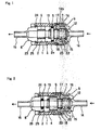
- the rotary barrel member 1 is provided with: a female screw portion 2 in an inner peripheral surfaced of the barrel member 1; a male screw portion 2a in an outer peripheral surface of one of opposite end portions of the barrel member 1. More specifically, the male screw portion 2a is formed in the outer peripheral surface of the right-hand end portion of the barrel member 1, as viewed in Fig. 1.
- the safety valve unit of the present invention is provided with a safety valve portion 3, which is provided in the same right-hand side of the barrel member 1 and also serves as a check valve.
- the above-mentioned cracking-pressure adjusting portion of the safety valve unit is incorporated in the rotary barrel member 1 to cooperate therewith so as to adjust the cracking pressure of the safety valve 3.
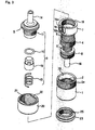
- the cracking-pressure adjusting portion of the valve unit is constructed of: a movable spring support 4 which is threadably engaged with the female screw portion 2 of the rotary barrel member 1; a pair of bellows 5, 6 each of which is disposed adjacent to each of opposite axial end surfaces of the movable spring support 4; a valve holder 7 disposed axially outside the right-hand one 5 of the bellows 5, 6 so as to be adjacent to this right-hand bellows 5; and, a bellows body member 8 disposed axially outside the left-hand one 6 of the bellows 5, 6 so as to be adjacent to this left-hand bellows 6, wherein the bellows body member 8 is provided with an outlet connection opening 16 which has a substantially circular-shaped form and extends axially outwardly or leftwardly, as viewed in Fig. 1.
- the safety valve unit of the present invention has its five components (i.e., the movable spring support 4, bellows 5, 6, valve holder 7 and the bellows body member 8) integrally formed with each other into one piece of a fluoropolymer resin.
- the safety valve unit of the present invention comprises the movable component 4, any sealing means is not required between adjacent ones of these five components. This is one of large advantages inherent in the safety valve unit of the present invention.
- the safety valve portion 3 of the safety valve unit of the present invention is of a conventional type, and is constructed of: a valve housing 11 which is threadably engaged with the valve holder 7 and housed in the holder 7; a valve element 12 which is movably retained in the valve housing 11; and, a compression coil spring 13 disposed between the movable valve element 12 and the stationary spring support 4.
- the valve housing 11 is provided with: a flange portion 9, which abuts against a right-hand axial end surface of the valve holder 7; and, an inlet connection opening 14 having a substantially circular-shaped form in cross section, through which the safety valve unit is inline-connected with a fluid circuit (not shown).
- the valve element 12 is constantly urged axially rightward under the influence of a resilient force exerted by the compression coil spring 13 into its closing position in which the valve element 12 has its axial head surface brought into press-contact with an O-ring 15 to shut off a fluid flow passing through the safety valve portion 3 of the valve unit.
- a fluid pressure in the circuit applied to the axial head surface of the valve element 12 becomes larger than the resilient force exerted by the compression coil spring 13
- the valve element 12 is moved leftward in Fig. 1 to have its axial head surface separated from the O-ring 15 to permit fluid to pass through the safety valve unit.
- the resilient force exerted by the compression coil spring 13 can be adjusted by turning the barrel member 1.
- the movable spring support 4 is axially moved so that the compression coil spring 13 is more compressed or expanded, whereby the initial resilient force exerted by the compression coil spring 13 is adjusted.
- the valve holder 7 is provided with a bellows mounting end portion, in which portion the bellows 5 has its right-hand axial end portion fixedly mounted.
- the bellows mounting end portion of the valve holder 7 is housed in the rotary barrel member 1, and is provided with an annular engaging groove 17, as shown in Figs. 1 and 4.
- an annular nail portion 18 is formed in an inner peripheral surface of a right-hand axial end portion of the barrel member 1 to correspond in position to the annular engaging groove 17 of the valve holder 7, and is slidably engaged with this annular engaging groove portion 17 of the valve holder 7.
- the valve holder 7 has its large-diameter portion disposed adjacent to the annular groove portion 17, which large-diameter portion is partially cut off to form a pair of diametrically opposed flat surface portions 19.
- the other area of the large-diameter portion of fhe valve holder 7 after completion of such cutting-off operation form a pair of diametrically opposed restriction walls 19b.
- each of the flat surface portions is provided with a scale 19a for indicating a displacement of a stopper ring 20, which will be described later.
- the stopper ring 20, in which the valve holder 7 is housed is constructed of a cylindrical element, and has its inner peripheral surface threaded to form a female screw portion therein.
- the stopper ring 20 is provided with an axial end opening 21 having a substantially circular-shaped form in cross section, in which opening 21 a pair of diametrically opposed sector portions each including a straight-line portion 22 are formed. These sector portions of the stopper ring 20 correspond in position to the flat surface portions 19 of the valve holder 7.
- the male screw portion 2a formed in the right-hand end portion of the barrel member 1 is inserted into the stopper ring 20 from the left-hand side of the stopper ring 20 as viewed in Fig. 1 in a condition in which the valve holder 7 has been already inserted into the stopper ring 20, and is then threadably engaged with the female screw portion of the stopper ring 20.
- the flat surface portions 19 of the valve holder 7 are brought into contact with the straight-line portions 22 of the opening 21 of the stopper ring 20.
- a retaining collar 23 is threadably engaged with the bellows bodymember 8 to support a right-hand axial end portion of the bellows body member 8 inside a left-hand axial end portion of the barrel member 1, as viewed in Fig. 1. More specifically, an annular engaging groove 24 is formed in an inner peripheral surface of the left-hand axial end portion of the barrel member. 1. Slidably engaged with this annular engaging groove 24 of the barrel member 1 is an annular nail portion 25 formed in an outer peripheral surface of the right-hand axial end portion of the retaining collar 23, as viewed in Fig. 2.
- the retaining collar 23 has its annular nail portion 25 snapped into the annular engaging groove 24 of the barrel member 1. Such snapped-in engagement established between the retaining collar 23 and the barrel member 1 enables the barrel member 1 to slidably rotate relative to the retaining collar 23 without any fear of dropping out of the retaining collar 23 in adjusting the cracking pressure of the safety valve unit.
- the stopper ring 20 As for the stopper ring 20 having been threadably engaged with the male screw portion 2a of the rotary barrel member 1, the straight-line portions 22 of the stopper ring-20 are brought into area contact with the flat surface portions 19 of the valve holder 7. Due to this, the stopper ring 20 can't be rotated together with the rotary barrel member 1 when the barrel member 1 is rotated. However, since the stopper ring 20 has its female screw portion threadably engaged with the male screw portion 2a of the rotary barrel member 1, the stopper ring 20 is axially displaced along the length of the compression coil spring 13 when the barrel member 1 is rotated by the user.
- the stopper ring 20 When the rotary barrel member 1 is then rotated counterclockwise, the stopper ring 20 begins to be axially displaced in the reverse direction, so that the straight-line portions 22 of the stopper ring 20 are eventually brought into contact with the flange portion 9 of the valve housing 11 to prevent any further counterclockwise rotation of the barrel member 1 from being made by the user. This also prevents any further axial displacement of the movable spring support 4 in the reverse direction from being made, as shown in Fig. 1. As is clear from the above description, the stopper ring 20 is capable of performing such restriction function.
- the amount of axial displacement of the stopper ring 20 is made proportional to the amount of axial displacement of the movable spring support 4. Due to this, it is possible for the user to know any axial position of the movable spring support 4 through a scale 19a provided in each of the flat surface portions 19 of the valve holder 7 even when the user can't watch the movable spring support 4 itself from the outside. In other words, due to such provisions of the scales 19a in the flat surface portions 19 of the valve holder 7, it is possible for the user to perform any desired adjustment of the cracking pressure of the safety valve unit of the present invention in an easy and an adequate manner.
- Fig. 4 shows a second embodiment of the safety valve unit of the present invention. This second embodiment is different from the first embodiment in construction of the cracking-pressure adjusting portion of the valve unit.
- this second embodiment of the safety valve unit is provided with a movable spring support 4a in place of that 4 of the first embodiment.
- the movable spring support 4a used in the second embodiment is provided with an outlet connection opening 16a in place of that 16 of the first embodiment, wherein the opening 16a has a substantially circular-shaped form in cross section. Due to the above construction in the second embodiment, when the movable spring support 4a of the second embodiment is axially displaced, its outlet connection opening 16a is also axially displaced together with the movable spring support 4a, as is clear from Fig. 5.
Landscapes
- Engineering & Computer Science (AREA)
- General Engineering & Computer Science (AREA)
- Mechanical Engineering (AREA)
- Health & Medical Sciences (AREA)
- Life Sciences & Earth Sciences (AREA)
- Hydrology & Water Resources (AREA)
- Public Health (AREA)
- Water Supply & Treatment (AREA)
- Environmental & Geological Engineering (AREA)
- Structural Engineering (AREA)
- Safety Valves (AREA)
- Compressor (AREA)
- Glass Compositions (AREA)
- Control Of Combustion (AREA)
Applications Claiming Priority (2)
| Application Number | Priority Date | Filing Date | Title |
|---|---|---|---|
| JP2004104186 | 2004-03-31 | ||
| JP2004104186A JP4548823B2 (ja) | 2004-03-31 | 2004-03-31 | 安全弁装置 |
Publications (3)
| Publication Number | Publication Date |
|---|---|
| EP1582787A2 true EP1582787A2 (de) | 2005-10-05 |
| EP1582787A3 EP1582787A3 (de) | 2005-12-07 |
| EP1582787B1 EP1582787B1 (de) | 2007-05-09 |
Family
ID=34880049
Family Applications (1)
| Application Number | Title | Priority Date | Filing Date |
|---|---|---|---|
| EP20050006803 Not-in-force EP1582787B1 (de) | 2004-03-31 | 2005-03-29 | Sicherheitsventil |
Country Status (6)
| Country | Link |
|---|---|
| US (1) | US7284568B2 (de) |
| EP (1) | EP1582787B1 (de) |
| JP (1) | JP4548823B2 (de) |
| KR (1) | KR101180126B1 (de) |
| AT (1) | ATE362068T1 (de) |
| DE (1) | DE602005001076T2 (de) |
Cited By (3)
| Publication number | Priority date | Publication date | Assignee | Title |
|---|---|---|---|---|
| WO2014179326A1 (en) | 2013-05-01 | 2014-11-06 | Bayer Medical Care Inc. | Fluid path set bolus control device |
| US9599240B2 (en) | 2012-06-28 | 2017-03-21 | Saint-Gobain Performance Plastics Corporation | Polymer bellows spring |
| CN110469700A (zh) * | 2019-09-05 | 2019-11-19 | 杨锋 | 一种小型自动启闭式泄压阀门 |
Families Citing this family (5)
| Publication number | Priority date | Publication date | Assignee | Title |
|---|---|---|---|---|
| GB2452867B (en) * | 2008-10-17 | 2009-08-05 | Cambridge Reactor Design Ltd | A valve assembly |
| GB2585035B (en) * | 2019-06-25 | 2023-04-26 | Intersurgical Ag | An adjustable valve |
| EP4048927A4 (de) * | 2019-08-29 | 2023-09-20 | Engineered Controls International, LLC | Druckentlastungsventil |
| US11879558B2 (en) * | 2021-02-05 | 2024-01-23 | The Boeing Company | Hydraulic pressure relief valve with integrated calibration mechanism |
| KR102556147B1 (ko) * | 2022-10-31 | 2023-07-19 | (주) 케이투앤 | 안전 밸브 |
Family Cites Families (18)
| Publication number | Priority date | Publication date | Assignee | Title |
|---|---|---|---|---|
| US347213A (en) * | 1886-08-10 | Safety-valve | ||
| US1322638A (en) * | 1919-11-25 | Safety-valve | ||
| US98697A (en) * | 1870-01-11 | Improvement in safety-valves | ||
| US2720890A (en) * | 1949-06-07 | 1955-10-18 | Francis H Stroud | Control of vacuum in internal combustion engine |
| US2770255A (en) * | 1952-08-16 | 1956-11-13 | Daniel And Florence Guggenheim | Dual-range safety valve |
| US2884952A (en) * | 1953-03-23 | 1959-05-05 | Avco Inc | Line hydraulic pressure relief valve |
| US3255774A (en) * | 1962-12-20 | 1966-06-14 | Nuclear Products Company | Adjustable inline relief valve |
| US3422840A (en) * | 1966-01-17 | 1969-01-21 | Grove Valve & Regulator Co | Relief valve with resilient seal means |
| US4428396A (en) * | 1978-07-19 | 1984-01-31 | City Tank Corporation | Adjustable valve assembly |
| US4545405A (en) * | 1983-11-09 | 1985-10-08 | Thomas Industries, Inc. | Multi-position relief valve |
| JPS61262274A (ja) * | 1985-05-11 | 1986-11-20 | Kioritz Corp | 往復動ポンプの調圧弁装置 |
| US4718442A (en) * | 1986-02-27 | 1988-01-12 | Helix Technology Corporation | Cryogenic refrigerator compressor with externally adjustable by-pass/relief valve |
| JPH0545897Y2 (de) * | 1989-04-14 | 1993-11-29 | ||
| JPH10122400A (ja) * | 1996-10-14 | 1998-05-15 | Shimadzu Corp | 圧力制御弁 |
| DE19815248A1 (de) * | 1998-02-09 | 1999-09-09 | Industriearmaturen Polte Gmbh | Überdrucksicherung |
| JP3528591B2 (ja) * | 1998-04-24 | 2004-05-17 | マックス株式会社 | 空気圧レギュレータ |
| JP2001065723A (ja) * | 1999-08-30 | 2001-03-16 | Maruyama Mfg Co Ltd | 調圧弁 |
| JP2005316988A (ja) * | 2004-03-31 | 2005-11-10 | Daisen Kk | 圧力制御弁及び複数の出力口を備えた圧力制御弁ユニット |
-
2004
- 2004-03-31 JP JP2004104186A patent/JP4548823B2/ja not_active Expired - Fee Related
-
2005
- 2005-03-29 EP EP20050006803 patent/EP1582787B1/de not_active Not-in-force
- 2005-03-29 DE DE200560001076 patent/DE602005001076T2/de active Active
- 2005-03-29 AT AT05006803T patent/ATE362068T1/de not_active IP Right Cessation
- 2005-03-30 KR KR1020050026710A patent/KR101180126B1/ko active IP Right Grant
- 2005-03-31 US US11/094,243 patent/US7284568B2/en active Active
Non-Patent Citations (1)
| Title |
|---|
| None |
Cited By (7)
| Publication number | Priority date | Publication date | Assignee | Title |
|---|---|---|---|---|
| US9599240B2 (en) | 2012-06-28 | 2017-03-21 | Saint-Gobain Performance Plastics Corporation | Polymer bellows spring |
| WO2014179326A1 (en) | 2013-05-01 | 2014-11-06 | Bayer Medical Care Inc. | Fluid path set bolus control device |
| US10441775B2 (en) | 2013-05-01 | 2019-10-15 | Bayer Healthcare Llc | Fluid path set bolus control device |
| EP2991721B1 (de) * | 2013-05-01 | 2020-03-11 | Bayer Healthcare LLC | Bolussteuerungsvorrichtung mit festgelegter fluidbahn |
| US11202898B2 (en) | 2013-05-01 | 2021-12-21 | Bayer Healthcare Llc | Fluid path set bolus control device |
| CN110469700A (zh) * | 2019-09-05 | 2019-11-19 | 杨锋 | 一种小型自动启闭式泄压阀门 |
| CN110469700B (zh) * | 2019-09-05 | 2020-12-04 | 台州市路桥鸿辉水暖厂 | 一种小型自动启闭式泄压阀门 |
Also Published As
| Publication number | Publication date |
|---|---|
| DE602005001076D1 (de) | 2007-06-21 |
| US7284568B2 (en) | 2007-10-23 |
| EP1582787B1 (de) | 2007-05-09 |
| EP1582787A3 (de) | 2005-12-07 |
| KR101180126B1 (ko) | 2012-09-05 |
| US20050217731A1 (en) | 2005-10-06 |
| KR20060045038A (ko) | 2006-05-16 |
| DE602005001076T2 (de) | 2008-01-10 |
| JP4548823B2 (ja) | 2010-09-22 |
| ATE362068T1 (de) | 2007-06-15 |
| JP2005291271A (ja) | 2005-10-20 |
Similar Documents
| Publication | Publication Date | Title |
|---|---|---|
| US7284568B2 (en) | Safety valve unit | |
| KR20070032821A (ko) | 볼 밸브 시트 구조 | |
| US10935153B2 (en) | Proportional flow control valve poppet with flow control needle | |
| JP3861206B2 (ja) | 流体制御器 | |
| US9115812B2 (en) | Plug valve with a spring biased plug | |
| CN110691932A (zh) | 比例夹管阀 | |
| JP2012031966A (ja) | 三方弁 | |
| JP4522833B2 (ja) | ニードルバルブ | |
| EP3369973B1 (de) | Regelventil | |
| JP2008144836A (ja) | メタルシートバタフライ弁 | |
| JP4566715B2 (ja) | ニードルバルブの調芯固定方法 | |
| JP4936219B2 (ja) | 湯水混合装置及びそれを備えた湯水混合水栓 | |
| JP2005351309A (ja) | バルブのボディおよびこれを備えたバルブ | |
| JP3928658B1 (ja) | 湯水混合装置及びそれを備えた湯水混合水栓 | |
| WO2015151310A1 (ja) | 絞り弁 | |
| JP2017201200A (ja) | 流量調整バルブ | |
| JP2006266403A (ja) | 混合弁 | |
| JP2006322475A (ja) | 管継手 | |
| US11976734B2 (en) | Proportional flow control valve | |
| JP2006057761A (ja) | 湯水混合弁 | |
| JP2007182921A (ja) | バルブシートおよびボールバルブ | |
| JP3285404B2 (ja) | 手動式弁装置 | |
| JP2006057761A5 (de) | ||
| TWM649645U (zh) | 球閥裝置 | |
| JP4146848B2 (ja) | 弁装置 |
Legal Events
| Date | Code | Title | Description |
|---|---|---|---|
| PUAI | Public reference made under article 153(3) epc to a published international application that has entered the european phase |
Free format text: ORIGINAL CODE: 0009012 |
|
| AK | Designated contracting states |
Kind code of ref document: A2 Designated state(s): AT BE BG CH CY CZ DE DK EE ES FI FR GB GR HU IE IS IT LI LT LU MC NL PL PT RO SE SI SK TR |
|
| AX | Request for extension of the european patent |
Extension state: AL BA HR LV MK YU |
|
| PUAL | Search report despatched |
Free format text: ORIGINAL CODE: 0009013 |
|
| AK | Designated contracting states |
Kind code of ref document: A3 Designated state(s): AT BE BG CH CY CZ DE DK EE ES FI FR GB GR HU IE IS IT LI LT LU MC NL PL PT RO SE SI SK TR |
|
| AX | Request for extension of the european patent |
Extension state: AL BA HR LV MK YU |
|
| 17P | Request for examination filed |
Effective date: 20060215 |
|
| AKX | Designation fees paid |
Designated state(s): AT BE BG CH CY CZ DE DK EE ES FI FR GB GR HU IE IS IT LI LT LU MC NL PL PT RO SE SI SK TR |
|
| GRAP | Despatch of communication of intention to grant a patent |
Free format text: ORIGINAL CODE: EPIDOSNIGR1 |
|
| GRAS | Grant fee paid |
Free format text: ORIGINAL CODE: EPIDOSNIGR3 |
|
| GRAA | (expected) grant |
Free format text: ORIGINAL CODE: 0009210 |
|
| AK | Designated contracting states |
Kind code of ref document: B1 Designated state(s): AT BE BG CH CY CZ DE DK EE ES FI FR GB GR HU IE IS IT LI LT LU MC NL PL PT RO SE SI SK TR |
|
| PG25 | Lapsed in a contracting state [announced via postgrant information from national office to epo] |
Ref country code: FI Free format text: LAPSE BECAUSE OF FAILURE TO SUBMIT A TRANSLATION OF THE DESCRIPTION OR TO PAY THE FEE WITHIN THE PRESCRIBED TIME-LIMIT Effective date: 20070509 Ref country code: CH Free format text: LAPSE BECAUSE OF FAILURE TO SUBMIT A TRANSLATION OF THE DESCRIPTION OR TO PAY THE FEE WITHIN THE PRESCRIBED TIME-LIMIT Effective date: 20070509 Ref country code: LI Free format text: LAPSE BECAUSE OF FAILURE TO SUBMIT A TRANSLATION OF THE DESCRIPTION OR TO PAY THE FEE WITHIN THE PRESCRIBED TIME-LIMIT Effective date: 20070509 |
|
| REG | Reference to a national code |
Ref country code: GB Ref legal event code: FG4D |
|
| REG | Reference to a national code |
Ref country code: CH Ref legal event code: EP |
|
| REG | Reference to a national code |
Ref country code: IE Ref legal event code: FG4D |
|
| REF | Corresponds to: |
Ref document number: 602005001076 Country of ref document: DE Date of ref document: 20070621 Kind code of ref document: P |
|
| PG25 | Lapsed in a contracting state [announced via postgrant information from national office to epo] |
Ref country code: SE Free format text: LAPSE BECAUSE OF FAILURE TO SUBMIT A TRANSLATION OF THE DESCRIPTION OR TO PAY THE FEE WITHIN THE PRESCRIBED TIME-LIMIT Effective date: 20070809 |
|
| PG25 | Lapsed in a contracting state [announced via postgrant information from national office to epo] |
Ref country code: ES Free format text: LAPSE BECAUSE OF FAILURE TO SUBMIT A TRANSLATION OF THE DESCRIPTION OR TO PAY THE FEE WITHIN THE PRESCRIBED TIME-LIMIT Effective date: 20070820 |
|
| PG25 | Lapsed in a contracting state [announced via postgrant information from national office to epo] |
Ref country code: IS Free format text: LAPSE BECAUSE OF FAILURE TO SUBMIT A TRANSLATION OF THE DESCRIPTION OR TO PAY THE FEE WITHIN THE PRESCRIBED TIME-LIMIT Effective date: 20070909 |
|
| NLV1 | Nl: lapsed or annulled due to failure to fulfill the requirements of art. 29p and 29m of the patents act | ||
| REG | Reference to a national code |
Ref country code: CH Ref legal event code: PL |
|
| PG25 | Lapsed in a contracting state [announced via postgrant information from national office to epo] |
Ref country code: PL Free format text: LAPSE BECAUSE OF FAILURE TO SUBMIT A TRANSLATION OF THE DESCRIPTION OR TO PAY THE FEE WITHIN THE PRESCRIBED TIME-LIMIT Effective date: 20070509 Ref country code: AT Free format text: LAPSE BECAUSE OF FAILURE TO SUBMIT A TRANSLATION OF THE DESCRIPTION OR TO PAY THE FEE WITHIN THE PRESCRIBED TIME-LIMIT Effective date: 20070509 |
|
| PG25 | Lapsed in a contracting state [announced via postgrant information from national office to epo] |
Ref country code: BE Free format text: LAPSE BECAUSE OF FAILURE TO SUBMIT A TRANSLATION OF THE DESCRIPTION OR TO PAY THE FEE WITHIN THE PRESCRIBED TIME-LIMIT Effective date: 20070509 |
|
| EN | Fr: translation not filed | ||
| PG25 | Lapsed in a contracting state [announced via postgrant information from national office to epo] |
Ref country code: SI Free format text: LAPSE BECAUSE OF FAILURE TO SUBMIT A TRANSLATION OF THE DESCRIPTION OR TO PAY THE FEE WITHIN THE PRESCRIBED TIME-LIMIT Effective date: 20070509 Ref country code: PT Free format text: LAPSE BECAUSE OF FAILURE TO SUBMIT A TRANSLATION OF THE DESCRIPTION OR TO PAY THE FEE WITHIN THE PRESCRIBED TIME-LIMIT Effective date: 20071009 Ref country code: BG Free format text: LAPSE BECAUSE OF FAILURE TO SUBMIT A TRANSLATION OF THE DESCRIPTION OR TO PAY THE FEE WITHIN THE PRESCRIBED TIME-LIMIT Effective date: 20070809 Ref country code: DK Free format text: LAPSE BECAUSE OF FAILURE TO SUBMIT A TRANSLATION OF THE DESCRIPTION OR TO PAY THE FEE WITHIN THE PRESCRIBED TIME-LIMIT Effective date: 20070509 Ref country code: CZ Free format text: LAPSE BECAUSE OF FAILURE TO SUBMIT A TRANSLATION OF THE DESCRIPTION OR TO PAY THE FEE WITHIN THE PRESCRIBED TIME-LIMIT Effective date: 20070509 Ref country code: NL Free format text: LAPSE BECAUSE OF FAILURE TO SUBMIT A TRANSLATION OF THE DESCRIPTION OR TO PAY THE FEE WITHIN THE PRESCRIBED TIME-LIMIT Effective date: 20070509 |
|
| PG25 | Lapsed in a contracting state [announced via postgrant information from national office to epo] |
Ref country code: SK Free format text: LAPSE BECAUSE OF FAILURE TO SUBMIT A TRANSLATION OF THE DESCRIPTION OR TO PAY THE FEE WITHIN THE PRESCRIBED TIME-LIMIT Effective date: 20070509 Ref country code: LT Free format text: LAPSE BECAUSE OF FAILURE TO SUBMIT A TRANSLATION OF THE DESCRIPTION OR TO PAY THE FEE WITHIN THE PRESCRIBED TIME-LIMIT Effective date: 20070509 |
|
| PLBE | No opposition filed within time limit |
Free format text: ORIGINAL CODE: 0009261 |
|
| STAA | Information on the status of an ep patent application or granted ep patent |
Free format text: STATUS: NO OPPOSITION FILED WITHIN TIME LIMIT |
|
| 26N | No opposition filed |
Effective date: 20080212 |
|
| PG25 | Lapsed in a contracting state [announced via postgrant information from national office to epo] |
Ref country code: GR Free format text: LAPSE BECAUSE OF FAILURE TO SUBMIT A TRANSLATION OF THE DESCRIPTION OR TO PAY THE FEE WITHIN THE PRESCRIBED TIME-LIMIT Effective date: 20070810 Ref country code: IT Free format text: LAPSE BECAUSE OF FAILURE TO SUBMIT A TRANSLATION OF THE DESCRIPTION OR TO PAY THE FEE WITHIN THE PRESCRIBED TIME-LIMIT Effective date: 20070509 |
|
| PG25 | Lapsed in a contracting state [announced via postgrant information from national office to epo] |
Ref country code: RO Free format text: LAPSE BECAUSE OF FAILURE TO SUBMIT A TRANSLATION OF THE DESCRIPTION OR TO PAY THE FEE WITHIN THE PRESCRIBED TIME-LIMIT Effective date: 20070509 |
|
| PG25 | Lapsed in a contracting state [announced via postgrant information from national office to epo] |
Ref country code: FR Free format text: LAPSE BECAUSE OF FAILURE TO SUBMIT A TRANSLATION OF THE DESCRIPTION OR TO PAY THE FEE WITHIN THE PRESCRIBED TIME-LIMIT Effective date: 20080104 |
|
| PG25 | Lapsed in a contracting state [announced via postgrant information from national office to epo] |
Ref country code: MC Free format text: LAPSE BECAUSE OF NON-PAYMENT OF DUE FEES Effective date: 20080331 |
|
| PG25 | Lapsed in a contracting state [announced via postgrant information from national office to epo] |
Ref country code: EE Free format text: LAPSE BECAUSE OF FAILURE TO SUBMIT A TRANSLATION OF THE DESCRIPTION OR TO PAY THE FEE WITHIN THE PRESCRIBED TIME-LIMIT Effective date: 20070509 Ref country code: IE Free format text: LAPSE BECAUSE OF NON-PAYMENT OF DUE FEES Effective date: 20080331 |
|
| PG25 | Lapsed in a contracting state [announced via postgrant information from national office to epo] |
Ref country code: CY Free format text: LAPSE BECAUSE OF FAILURE TO SUBMIT A TRANSLATION OF THE DESCRIPTION OR TO PAY THE FEE WITHIN THE PRESCRIBED TIME-LIMIT Effective date: 20070509 |
|
| GBPC | Gb: european patent ceased through non-payment of renewal fee |
Effective date: 20090329 |
|
| PG25 | Lapsed in a contracting state [announced via postgrant information from national office to epo] |
Ref country code: GB Free format text: LAPSE BECAUSE OF NON-PAYMENT OF DUE FEES Effective date: 20090329 |
|
| PG25 | Lapsed in a contracting state [announced via postgrant information from national office to epo] |
Ref country code: LU Free format text: LAPSE BECAUSE OF NON-PAYMENT OF DUE FEES Effective date: 20080329 Ref country code: HU Free format text: LAPSE BECAUSE OF FAILURE TO SUBMIT A TRANSLATION OF THE DESCRIPTION OR TO PAY THE FEE WITHIN THE PRESCRIBED TIME-LIMIT Effective date: 20071110 |
|
| PG25 | Lapsed in a contracting state [announced via postgrant information from national office to epo] |
Ref country code: TR Free format text: LAPSE BECAUSE OF FAILURE TO SUBMIT A TRANSLATION OF THE DESCRIPTION OR TO PAY THE FEE WITHIN THE PRESCRIBED TIME-LIMIT Effective date: 20070509 |
|
| PGFP | Annual fee paid to national office [announced via postgrant information from national office to epo] |
Ref country code: DE Payment date: 20220316 Year of fee payment: 18 |
|
| REG | Reference to a national code |
Ref country code: DE Ref legal event code: R119 Ref document number: 602005001076 Country of ref document: DE |
|
| PG25 | Lapsed in a contracting state [announced via postgrant information from national office to epo] |
Ref country code: DE Free format text: LAPSE BECAUSE OF NON-PAYMENT OF DUE FEES Effective date: 20231003 |