EP1582339B1 - Fuel tube - Google Patents
Fuel tube Download PDFInfo
- Publication number
- EP1582339B1 EP1582339B1 EP05006967A EP05006967A EP1582339B1 EP 1582339 B1 EP1582339 B1 EP 1582339B1 EP 05006967 A EP05006967 A EP 05006967A EP 05006967 A EP05006967 A EP 05006967A EP 1582339 B1 EP1582339 B1 EP 1582339B1
- Authority
- EP
- European Patent Office
- Prior art keywords
- fuel tube
- resin
- fuel
- layer
- outer layer
- Prior art date
- Legal status (The legal status is an assumption and is not a legal conclusion. Google has not performed a legal analysis and makes no representation as to the accuracy of the status listed.)
- Expired - Lifetime
Links
- 239000000446 fuel Substances 0.000 title claims description 90
- 229920005989 resin Polymers 0.000 claims description 40
- 239000011347 resin Substances 0.000 claims description 40
- 230000035699 permeability Effects 0.000 claims description 37
- 239000011342 resin composition Substances 0.000 claims description 28
- 239000000853 adhesive Substances 0.000 claims description 25
- 229920000098 polyolefin Polymers 0.000 claims description 23
- 101000576320 Homo sapiens Max-binding protein MNT Proteins 0.000 claims description 18
- 229920006121 Polyxylylene adipamide Polymers 0.000 claims description 18
- -1 polyethylene copolymer Polymers 0.000 claims description 9
- 229920000089 Cyclic olefin copolymer Polymers 0.000 claims description 8
- 239000004014 plasticizer Substances 0.000 claims description 8
- 229920001400 block copolymer Polymers 0.000 claims description 7
- 229920001577 copolymer Polymers 0.000 claims description 7
- 239000004698 Polyethylene Substances 0.000 claims description 6
- 229920001971 elastomer Polymers 0.000 claims description 6
- 239000000806 elastomer Substances 0.000 claims description 6
- 229920000728 polyester Polymers 0.000 claims description 4
- 229920000573 polyethylene Polymers 0.000 claims description 4
- 229940124530 sulfonamide Drugs 0.000 claims description 4
- 239000004711 α-olefin Substances 0.000 claims description 3
- 239000004721 Polyphenylene oxide Substances 0.000 claims description 2
- 229920000570 polyether Polymers 0.000 claims description 2
- 125000000565 sulfonamide group Chemical group 0.000 claims 1
- 239000010410 layer Substances 0.000 description 77
- 230000000052 comparative effect Effects 0.000 description 14
- 238000012360 testing method Methods 0.000 description 13
- 230000001070 adhesive effect Effects 0.000 description 12
- 238000005452 bending Methods 0.000 description 12
- 239000004734 Polyphenylene sulfide Substances 0.000 description 11
- 229920000069 polyphenylene sulfide Polymers 0.000 description 11
- 238000003475 lamination Methods 0.000 description 8
- 239000000203 mixture Substances 0.000 description 8
- 229920006122 polyamide resin Polymers 0.000 description 8
- 239000000463 material Substances 0.000 description 6
- 238000005259 measurement Methods 0.000 description 6
- 229920000571 Nylon 11 Polymers 0.000 description 5
- 239000011229 interlayer Substances 0.000 description 5
- LFQSCWFLJHTTHZ-UHFFFAOYSA-N Ethanol Chemical compound CCO LFQSCWFLJHTTHZ-UHFFFAOYSA-N 0.000 description 4
- IPRJXAGUEGOFGG-UHFFFAOYSA-N N-butylbenzenesulfonamide Chemical compound CCCCNS(=O)(=O)C1=CC=CC=C1 IPRJXAGUEGOFGG-UHFFFAOYSA-N 0.000 description 4
- WNLRTRBMVRJNCN-UHFFFAOYSA-N adipic acid Chemical compound OC(=O)CCCCC(O)=O WNLRTRBMVRJNCN-UHFFFAOYSA-N 0.000 description 4
- 239000003795 chemical substances by application Substances 0.000 description 4
- 230000000694 effects Effects 0.000 description 4
- 239000000945 filler Substances 0.000 description 4
- 239000002356 single layer Substances 0.000 description 4
- 229920000219 Ethylene vinyl alcohol Polymers 0.000 description 3
- YXFVVABEGXRONW-UHFFFAOYSA-N Toluene Chemical compound CC1=CC=CC=C1 YXFVVABEGXRONW-UHFFFAOYSA-N 0.000 description 3
- 239000000654 additive Substances 0.000 description 3
- 238000001816 cooling Methods 0.000 description 3
- 238000007599 discharging Methods 0.000 description 3
- 229920000840 ethylene tetrafluoroethylene copolymer Polymers 0.000 description 3
- 238000001125 extrusion Methods 0.000 description 3
- 238000000034 method Methods 0.000 description 3
- 238000004513 sizing Methods 0.000 description 3
- OFOBLEOULBTSOW-UHFFFAOYSA-N Propanedioic acid Natural products OC(=O)CC(O)=O OFOBLEOULBTSOW-UHFFFAOYSA-N 0.000 description 2
- VYPSYNLAJGMNEJ-UHFFFAOYSA-N Silicium dioxide Chemical compound O=[Si]=O VYPSYNLAJGMNEJ-UHFFFAOYSA-N 0.000 description 2
- FDLQZKYLHJJBHD-UHFFFAOYSA-N [3-(aminomethyl)phenyl]methanamine Chemical compound NCC1=CC=CC(CN)=C1 FDLQZKYLHJJBHD-UHFFFAOYSA-N 0.000 description 2
- 239000002253 acid Substances 0.000 description 2
- 239000012790 adhesive layer Substances 0.000 description 2
- 235000011037 adipic acid Nutrition 0.000 description 2
- 239000001361 adipic acid Substances 0.000 description 2
- 150000001412 amines Chemical class 0.000 description 2
- 239000003963 antioxidant agent Substances 0.000 description 2
- 230000003078 antioxidant effect Effects 0.000 description 2
- 235000006708 antioxidants Nutrition 0.000 description 2
- JBKVHLHDHHXQEQ-UHFFFAOYSA-N epsilon-caprolactam Chemical compound O=C1CCCCCN1 JBKVHLHDHHXQEQ-UHFFFAOYSA-N 0.000 description 2
- UFRKOOWSQGXVKV-UHFFFAOYSA-N ethene;ethenol Chemical compound C=C.OC=C UFRKOOWSQGXVKV-UHFFFAOYSA-N 0.000 description 2
- 239000005038 ethylene vinyl acetate Substances 0.000 description 2
- 239000004715 ethylene vinyl alcohol Substances 0.000 description 2
- 239000000835 fiber Substances 0.000 description 2
- NAQMVNRVTILPCV-UHFFFAOYSA-N hexane-1,6-diamine Chemical compound NCCCCCCN NAQMVNRVTILPCV-UHFFFAOYSA-N 0.000 description 2
- 230000004048 modification Effects 0.000 description 2
- 238000012986 modification Methods 0.000 description 2
- 238000000465 moulding Methods 0.000 description 2
- 229920001200 poly(ethylene-vinyl acetate) Polymers 0.000 description 2
- 239000003223 protective agent Substances 0.000 description 2
- KIDHWZJUCRJVML-UHFFFAOYSA-N putrescine Chemical compound NCCCCN KIDHWZJUCRJVML-UHFFFAOYSA-N 0.000 description 2
- CXMXRPHRNRROMY-UHFFFAOYSA-N sebacic acid Chemical compound OC(=O)CCCCCCCCC(O)=O CXMXRPHRNRROMY-UHFFFAOYSA-N 0.000 description 2
- 150000003456 sulfonamides Chemical class 0.000 description 2
- 229920005992 thermoplastic resin Polymers 0.000 description 2
- RNFJDJUURJAICM-UHFFFAOYSA-N 2,2,4,4,6,6-hexaphenoxy-1,3,5-triaza-2$l^{5},4$l^{5},6$l^{5}-triphosphacyclohexa-1,3,5-triene Chemical compound N=1P(OC=2C=CC=CC=2)(OC=2C=CC=CC=2)=NP(OC=2C=CC=CC=2)(OC=2C=CC=CC=2)=NP=1(OC=1C=CC=CC=1)OC1=CC=CC=C1 RNFJDJUURJAICM-UHFFFAOYSA-N 0.000 description 1
- SMZOUWXMTYCWNB-UHFFFAOYSA-N 2-(2-methoxy-5-methylphenyl)ethanamine Chemical compound COC1=CC=C(C)C=C1CCN SMZOUWXMTYCWNB-UHFFFAOYSA-N 0.000 description 1
- NIXOWILDQLNWCW-UHFFFAOYSA-N 2-Propenoic acid Natural products OC(=O)C=C NIXOWILDQLNWCW-UHFFFAOYSA-N 0.000 description 1
- GMGJRHXQPCKDFY-UHFFFAOYSA-N 2-methyl-3-phenyl-n-propan-2-ylbenzenesulfonamide Chemical compound CC(C)NS(=O)(=O)C1=CC=CC(C=2C=CC=CC=2)=C1C GMGJRHXQPCKDFY-UHFFFAOYSA-N 0.000 description 1
- KLWUWNHLZITTHU-UHFFFAOYSA-N 2-methyl-n-phenylbenzenesulfonamide Chemical compound CC1=CC=CC=C1S(=O)(=O)NC1=CC=CC=C1 KLWUWNHLZITTHU-UHFFFAOYSA-N 0.000 description 1
- COOHCXJXLLVMIK-UHFFFAOYSA-N 2-phenyl-n-propan-2-ylbenzenesulfonamide Chemical compound CC(C)NS(=O)(=O)C1=CC=CC=C1C1=CC=CC=C1 COOHCXJXLLVMIK-UHFFFAOYSA-N 0.000 description 1
- YLZOPXRUQYQQID-UHFFFAOYSA-N 3-(2,4,6,7-tetrahydrotriazolo[4,5-c]pyridin-5-yl)-1-[4-[2-[[3-(trifluoromethoxy)phenyl]methylamino]pyrimidin-5-yl]piperazin-1-yl]propan-1-one Chemical compound N1N=NC=2CN(CCC=21)CCC(=O)N1CCN(CC1)C=1C=NC(=NC=1)NCC1=CC(=CC=C1)OC(F)(F)F YLZOPXRUQYQQID-UHFFFAOYSA-N 0.000 description 1
- DEXFNLNNUZKHNO-UHFFFAOYSA-N 6-[3-[4-[2-(2,3-dihydro-1H-inden-2-ylamino)pyrimidin-5-yl]piperidin-1-yl]-3-oxopropyl]-3H-1,3-benzoxazol-2-one Chemical compound C1C(CC2=CC=CC=C12)NC1=NC=C(C=N1)C1CCN(CC1)C(CCC1=CC2=C(NC(O2)=O)C=C1)=O DEXFNLNNUZKHNO-UHFFFAOYSA-N 0.000 description 1
- SLXKOJJOQWFEFD-UHFFFAOYSA-N 6-aminohexanoic acid Chemical compound NCCCCCC(O)=O SLXKOJJOQWFEFD-UHFFFAOYSA-N 0.000 description 1
- GVNWZKBFMFUVNX-UHFFFAOYSA-N Adipamide Chemical compound NC(=O)CCCCC(N)=O GVNWZKBFMFUVNX-UHFFFAOYSA-N 0.000 description 1
- OKTJSMMVPCPJKN-UHFFFAOYSA-N Carbon Chemical compound [C] OKTJSMMVPCPJKN-UHFFFAOYSA-N 0.000 description 1
- PIICEJLVQHRZGT-UHFFFAOYSA-N Ethylenediamine Chemical compound NCCN PIICEJLVQHRZGT-UHFFFAOYSA-N 0.000 description 1
- NHTMVDHEPJAVLT-UHFFFAOYSA-N Isooctane Chemical compound CC(C)CC(C)(C)C NHTMVDHEPJAVLT-UHFFFAOYSA-N 0.000 description 1
- CERQOIWHTDAKMF-UHFFFAOYSA-N Methacrylic acid Chemical compound CC(=C)C(O)=O CERQOIWHTDAKMF-UHFFFAOYSA-N 0.000 description 1
- 229920000299 Nylon 12 Polymers 0.000 description 1
- 229920002164 Polyalkylene glycol copolymer Polymers 0.000 description 1
- 239000004743 Polypropylene Substances 0.000 description 1
- 229910021536 Zeolite Inorganic materials 0.000 description 1
- ISKQADXMHQSTHK-UHFFFAOYSA-N [4-(aminomethyl)phenyl]methanamine Chemical compound NCC1=CC=C(CN)C=C1 ISKQADXMHQSTHK-UHFFFAOYSA-N 0.000 description 1
- 230000000996 additive effect Effects 0.000 description 1
- 125000001931 aliphatic group Chemical group 0.000 description 1
- 229920006231 aramid fiber Polymers 0.000 description 1
- CJYXCQLOZNIMFP-UHFFFAOYSA-N azocan-2-one Chemical compound O=C1CCCCCCN1 CJYXCQLOZNIMFP-UHFFFAOYSA-N 0.000 description 1
- 239000004927 clay Substances 0.000 description 1
- 229910052570 clay Inorganic materials 0.000 description 1
- 239000003086 colorant Substances 0.000 description 1
- 150000001875 compounds Chemical class 0.000 description 1
- 239000007822 coupling agent Substances 0.000 description 1
- 239000013078 crystal Substances 0.000 description 1
- JVSWJIKNEAIKJW-UHFFFAOYSA-N dimethyl-hexane Natural products CCCCCC(C)C JVSWJIKNEAIKJW-UHFFFAOYSA-N 0.000 description 1
- HNPSIPDUKPIQMN-UHFFFAOYSA-N dioxosilane;oxo(oxoalumanyloxy)alumane Chemical compound O=[Si]=O.O=[Al]O[Al]=O HNPSIPDUKPIQMN-UHFFFAOYSA-N 0.000 description 1
- QFTYSVGGYOXFRQ-UHFFFAOYSA-N dodecane-1,12-diamine Chemical compound NCCCCCCCCCCCCN QFTYSVGGYOXFRQ-UHFFFAOYSA-N 0.000 description 1
- 239000003063 flame retardant Substances 0.000 description 1
- 239000004088 foaming agent Substances 0.000 description 1
- 125000000524 functional group Chemical group 0.000 description 1
- 239000003365 glass fiber Substances 0.000 description 1
- 239000010439 graphite Substances 0.000 description 1
- 229910002804 graphite Inorganic materials 0.000 description 1
- 239000000314 lubricant Substances 0.000 description 1
- VZCYOOQTPOCHFL-UPHRSURJSA-N maleic acid Chemical compound OC(=O)\C=C/C(O)=O VZCYOOQTPOCHFL-UPHRSURJSA-N 0.000 description 1
- 239000011976 maleic acid Substances 0.000 description 1
- FPYJFEHAWHCUMM-UHFFFAOYSA-N maleic anhydride Chemical compound O=C1OC(=O)C=C1 FPYJFEHAWHCUMM-UHFFFAOYSA-N 0.000 description 1
- 238000004519 manufacturing process Methods 0.000 description 1
- 239000002184 metal Substances 0.000 description 1
- 229920003145 methacrylic acid copolymer Polymers 0.000 description 1
- 229940117841 methacrylic acid copolymer Drugs 0.000 description 1
- 229920003146 methacrylic ester copolymer Polymers 0.000 description 1
- ORGRWSGBPBXACJ-UHFFFAOYSA-N n,2-dibutylbenzenesulfonamide Chemical compound CCCCNS(=O)(=O)C1=CC=CC=C1CCCC ORGRWSGBPBXACJ-UHFFFAOYSA-N 0.000 description 1
- BAJXNEYFJDMIFP-UHFFFAOYSA-N n,2-dimethylbenzenesulfonamide Chemical compound CNS(=O)(=O)C1=CC=CC=C1C BAJXNEYFJDMIFP-UHFFFAOYSA-N 0.000 description 1
- ZBHYNHDKSANFJN-UHFFFAOYSA-N n-butyl-2-methylbenzenesulfonamide Chemical compound CCCCNS(=O)(=O)C1=CC=CC=C1C ZBHYNHDKSANFJN-UHFFFAOYSA-N 0.000 description 1
- JAPMJERNFQQJMN-UHFFFAOYSA-N n-butyl-2-phenylbenzenesulfonamide Chemical compound CCCCNS(=O)(=O)C1=CC=CC=C1C1=CC=CC=C1 JAPMJERNFQQJMN-UHFFFAOYSA-N 0.000 description 1
- PCUIOYSTPIQEFH-UHFFFAOYSA-N n-butyl-2-propan-2-ylbenzenesulfonamide Chemical compound CCCCNS(=O)(=O)C1=CC=CC=C1C(C)C PCUIOYSTPIQEFH-UHFFFAOYSA-N 0.000 description 1
- NATWUQFQFMZVMT-UHFFFAOYSA-N n-ethyl-2-methylbenzenesulfonamide Chemical compound CCNS(=O)(=O)C1=CC=CC=C1C NATWUQFQFMZVMT-UHFFFAOYSA-N 0.000 description 1
- SKERWNIJEZZECH-UHFFFAOYSA-N n-hexylbenzenesulfonamide Chemical compound CCCCCCNS(=O)(=O)C1=CC=CC=C1 SKERWNIJEZZECH-UHFFFAOYSA-N 0.000 description 1
- ONGMSIYISVEKDB-UHFFFAOYSA-N n-octylbenzenesulfonamide Chemical compound CCCCCCCCNS(=O)(=O)C1=CC=CC=C1 ONGMSIYISVEKDB-UHFFFAOYSA-N 0.000 description 1
- XAUGWFWQVYXATQ-UHFFFAOYSA-N n-phenylbenzenesulfonamide Chemical compound C=1C=CC=CC=1S(=O)(=O)NC1=CC=CC=C1 XAUGWFWQVYXATQ-UHFFFAOYSA-N 0.000 description 1
- OKPTYPHVKNNPSG-UHFFFAOYSA-N n-propylbenzenesulfonamide Chemical compound CCCNS(=O)(=O)C1=CC=CC=C1 OKPTYPHVKNNPSG-UHFFFAOYSA-N 0.000 description 1
- SXJVFQLYZSNZBT-UHFFFAOYSA-N nonane-1,9-diamine Chemical compound NCCCCCCCCCN SXJVFQLYZSNZBT-UHFFFAOYSA-N 0.000 description 1
- 150000001451 organic peroxides Chemical class 0.000 description 1
- 229910052698 phosphorus Inorganic materials 0.000 description 1
- 239000011574 phosphorus Substances 0.000 description 1
- 229920003023 plastic Polymers 0.000 description 1
- 239000004033 plastic Substances 0.000 description 1
- 229920001748 polybutylene Polymers 0.000 description 1
- 229920013716 polyethylene resin Polymers 0.000 description 1
- 229920000642 polymer Polymers 0.000 description 1
- 229920001155 polypropylene Polymers 0.000 description 1
- HNJBEVLQSNELDL-UHFFFAOYSA-N pyrrolidin-2-one Chemical compound O=C1CCCN1 HNJBEVLQSNELDL-UHFFFAOYSA-N 0.000 description 1
- 239000000377 silicon dioxide Substances 0.000 description 1
- 239000000344 soap Substances 0.000 description 1
- 239000000126 substance Substances 0.000 description 1
- 239000000454 talc Substances 0.000 description 1
- 229910052623 talc Inorganic materials 0.000 description 1
- 238000010998 test method Methods 0.000 description 1
- 229920002725 thermoplastic elastomer Polymers 0.000 description 1
- VZCYOOQTPOCHFL-UHFFFAOYSA-N trans-butenedioic acid Natural products OC(=O)C=CC(O)=O VZCYOOQTPOCHFL-UHFFFAOYSA-N 0.000 description 1
- KLNPWTHGTVSSEU-UHFFFAOYSA-N undecane-1,11-diamine Chemical compound NCCCCCCCCCCCN KLNPWTHGTVSSEU-UHFFFAOYSA-N 0.000 description 1
- 239000010456 wollastonite Substances 0.000 description 1
- 229910052882 wollastonite Inorganic materials 0.000 description 1
- 239000010457 zeolite Substances 0.000 description 1
Images
Classifications
-
- F—MECHANICAL ENGINEERING; LIGHTING; HEATING; WEAPONS; BLASTING
- F16—ENGINEERING ELEMENTS AND UNITS; GENERAL MEASURES FOR PRODUCING AND MAINTAINING EFFECTIVE FUNCTIONING OF MACHINES OR INSTALLATIONS; THERMAL INSULATION IN GENERAL
- F16L—PIPES; JOINTS OR FITTINGS FOR PIPES; SUPPORTS FOR PIPES, CABLES OR PROTECTIVE TUBING; MEANS FOR THERMAL INSULATION IN GENERAL
- F16L11/00—Hoses, i.e. flexible pipes
- F16L11/04—Hoses, i.e. flexible pipes made of rubber or flexible plastics
- F16L2011/047—Hoses, i.e. flexible pipes made of rubber or flexible plastics with a diffusion barrier layer
-
- Y—GENERAL TAGGING OF NEW TECHNOLOGICAL DEVELOPMENTS; GENERAL TAGGING OF CROSS-SECTIONAL TECHNOLOGIES SPANNING OVER SEVERAL SECTIONS OF THE IPC; TECHNICAL SUBJECTS COVERED BY FORMER USPC CROSS-REFERENCE ART COLLECTIONS [XRACs] AND DIGESTS
- Y10—TECHNICAL SUBJECTS COVERED BY FORMER USPC
- Y10T—TECHNICAL SUBJECTS COVERED BY FORMER US CLASSIFICATION
- Y10T428/00—Stock material or miscellaneous articles
- Y10T428/13—Hollow or container type article [e.g., tube, vase, etc.]
- Y10T428/1352—Polymer or resin containing [i.e., natural or synthetic]
- Y10T428/139—Open-ended, self-supporting conduit, cylinder, or tube-type article
- Y10T428/1393—Multilayer [continuous layer]
Definitions
- the present invention relates to a fuel tube in which fuel such as gasoline, alcohol gasoline or sour gasoline flows.
- a fuel tube having an inner layer made of a PPS resin and a functional group-containing thermoplastic resin, and an outer layer made of another thermoplastic resin than the PPS resin has been described in JP-A-10-138372 .
- a fuel tube having an inner layer made of a resin composition containing a metaxylylene group-containing polyamide resin and a modified polyester elastomer, and an outer layer made of a polyester elastomer has been described in JP-A-4-86257 .
- a fuel tube having an inner layer made of a low fuel permeability resin such as a PPS resin, and an outer layer made of a thermoplastic elastomer has been described in JP2000-329266A .
- the inner layer and the outer layer need to be bonded to each other by sufficient interlayer adhesive power so as not to be separated easily. It is however impossible to obtain sufficient interlayer adhesive power between the inner layer and the outer layer self-bonded to each other by direct contact because adhesion between the material of the inner layer and the material of the outer layer in the fuel tube produced by lamination in the related art low. It is therefore necessary to interpose an adhesive agent between the inner layer and the outer layer or add an adhesive agent into each of the materials of the inner and outer layers.
- EP 1 223 030 A2 discloses a fuel tube, comprising an inner wall layer with a three layer structure, wherein the innermost layer and the outer layer are made of a flexible PPS (PPS including an olefin polymer) and the intermediate layer interposed therebetween is made of common PPS.
- PPS polystyrene
- an object of the invention is to provide a fuel tube in which a good balance between the two characteristics of low fuel permeability and high flexibility can be attained by lamination and in which an inner layer and an outer layer can be self-bonded to each other by sufficient interlayer adhesive power without interposition/addition of any adhesive agent.
- a fuel tube including a laminate of an inner layer made of a resin composition containing a low fuel permeability resin as a main component and containing substantially no olefin polymer component, and an outer layer being made of a resin composition containing the low fuel permeability resin as a main component and containing substantially an olefin polymer component, wherein the inner layer and the outer layer are substantially self-bonded to each other without an adhesive agent, characterised in that the low fuel permeability resin is an MXD6 resin.
- containing substantially no olefin polymer component implies the case where a small amount of olefin copolymer component to exert no influence on fuel permeability may be contained, besides the case where no olefin polymer component is contained.
- the phrase containing substantially an olefin polymer component implies the case where a sufficient amount of olefin polymer component to reduce the elastic modulus is contained.
- the inner and outer layers can be self-bonded to each other by sufficient interlayer adhesive power without interposition/addition of any adhesive agent.
- a fuel tube includes a laminate of an inner layer and an outer layer, the inner layer being made of a resin composition containing an MXD6 resin, which is a low fuel permeability resin, as a main component but substantially containing no olefin polymer component, the outer layer being made of a resin composition containing the same low fuel permeability resin as the low fuel permeability resin of the inner layer as a main component and substantially containing an olefin polymer component, wherein the inner layer and the outer layer are laminated so as to be substantially self-bonded to each other without interposition of any adhesive agent.
- the amount of the olefin polymer component is from 20 to 60 % by weight.
- the MXD6 resin used in each of the inner and outer layers in this invention is a polyamide resin prepared from metaxylylene diamine and adipic acid.
- a polyamide resin having an average molecular weight of 20000 or higher is preferred and a polyamide resin having an average molecular weight of 30000 or higher is especially preferred.
- the olefin polymer component used on the outer layer side is a carboxylic anhydride- or carboxylic acid-modified elastomer of at least one member selected from the group consisting of polyolefin,polyethylene copolymer, hydrogenated styrene-ethylene-butadiene block copolymer, polyester-polyester block copolymer, and polyester-polyether block copolymer.
- MXD6 resin examples include carboxylic anhydride- or carboxylic acid-modified elastomers of polyethylene, polypropylene, ethylene- ⁇ -olefin copolymer, ethylene-diene copolymer, ethylene-acrylic ester copolymer, ethylene-methacrylic ester copolymer, ethylene-acrylic acid-methacrylic acid copolymer, ethylene-methacrylate copolymer, ethylene-vinyl acetate copolymer, saponified ethylene-vinyl acetate copolymer, polybutylene terephthalate-polybutylene adipate block copolymer, polybutylene terephthalate-polylactone copolymer, polyethylene terephthalate-polyalkylene glycol copolymer, etc.
- this modification is made by organic peroxide and unsaturated acid such as maleic acid, methacrylic acid, acrylic acid or maleic anhydride.
- unsaturated acid such as maleic acid, methacrylic acid, acrylic acid or maleic anhydride.
- acid-modified ethylene- ⁇ -olefin copolymer can be used.
- maleic acid-modified ethylene-butene copolymer can be used.
- the amount of the olefin copolymer component is not particularly limited but may be selected to be preferably in a range of from 20 to 60 by weight, especially preferably in a range from 30 to 50 % by weight. If the amount of the olefin copolymer component is smaller than 20 % by weight, the flexibility shows a tendency toward decrease because the elastic modulus becomes high. If the amount of the olefin copolymer component is larger than 60 % by weight, heat resistance or chemical resistance shows a tendency toward decrease.
- the resin composition used in the invention includes an MXD6 resin as the low fuel permeability resin as a main component, additives which will be described below may be mixed:
- a polyamide resin can be added as another resin than the MXD6 resin if the effect of the invention is not spoilt.
- examples of an amine component of the polyamide resin include metaxylylene diamine, paraxylylene diamine, ethylene diamine, tetramethylene diamine, hexamethylene diamine, nonamethylene diamine, undecamethylene diamine, dodecamethylenediamine, etc.
- the amine component is not limited thereto.
- Aliphatic dicarboxylic acid such as adipic acid or sebacic acid is used as an acid component of the polyamide resin.
- These polyamide resins may be copolymerized with ⁇ -caprolactam, 6-aminocapronic acid, ⁇ -enantholactam, ⁇ -pyrrolidone, etc. or may be blended with these polymers.
- Sulfonamide can be used as the plasticizer added to the MXD6 resin by way of example.
- the sulfonamide include N-propyl-benzene sulfonamide, N-butyl-benzene sulfonamide, N-hexyl-benzene sulfonamide, N-octyl-benzene sulfonamide, N-phenyl-benzene sulfonamide, N-dimethylphenyl-benzene sulfonamide, N-isopropylphenyl-benzene sulfonamide, N-butylphenyl-benzene sulfonamide, N-methyl-methylbenzene sulfonamide, N-ethyl-methylbenzene sulfonamide, N-butyl-methylbenzene sulfonamide, N-butyl-butylbenzene sulfonamide, N-butyl-iso
- An anti-oxidant such as a phenyl compound or a phosphorus compound may be preferably added in order to keep high heat resistance and heat stability.
- a general additive such as a coupling agent, a crystal seed agent, metal soap, a releasant, a color protecting agent, a lubricant, an ultraviolet-protecting agent, a colorant, a flame retardant, a foaming agent, an electrically conducting agent, etc. can be mixed as a modifying agent.
- Another layer having any one of the characteristics of these agents may be added.
- a filler e.g. fiber filler such as glass fiber or aramid fiber, non-fiber filler such as talc, wollastonite, zeolite, clay, silica or graphite, and so on
- fiber filler such as glass fiber or aramid fiber
- non-fiber filler such as talc, wollastonite, zeolite, clay, silica or graphite, and so on
- the thickness of the inner layer is not particularly limited but may be preferably selected to be in a range of from 0.05 to 0.4 mm. If the thickness is smaller than 0.05 mm, fuel permeability shows a tendency toward increase. If the thickness is larger than 0.4 mm, flexibility shows a tendency toward decrease. Incidentally, the thickness of the outer layer is not particularly limited.
- the shape of the fuel tube is not limited to a smooth cylindrical shape and may include the case where at least one part of the fuel tube is shaped like a bellows.
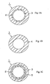
- Figs. 1A to 1C Resin compositions shown in Tables 1 to 3 were used as Examples and Comparative Examples.
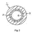
- Fig. 1A shows the case where the inner layer 2 and the outer layer 3 are laminated so as to be bonded to each other without interposition of any adhesive agent. This case corresponds to each of Examples 2-1 to 2-6 and Comparative Examples 4 and 5.
- Fig. 1B shows the case where the fuel tube 1 has a single layer 4. This case corresponds to each of Comparative Examples 2-1 to 2-3 and Comparative Example 3.
- Fig. 1A shows the case where the inner layer 2 and the outer layer 3 are laminated so as to be bonded to each other without interposition of any adhesive agent. This case corresponds to each of Examples 2-1 to 2-6 and Comparative Examples 4 and 5.
- Fig. 1B shows the case where the fuel tube 1 has a single layer 4. This
- Example 1C shows the case where the inner layer 2 and the outer layer 3 are laminated substantially through an adhesive agent 5 and bonded to each other by the adhesive agent 5.
- This case corresponds to Comparative Example 6.
- Inner layer Composition MXD6 (wt%) 100 100 100 100 100 100 100 100 100 100 100 100 100 Single elastic modulus (MPa) 3500 3500 3500 3500 3500 3500 3500 3500 3500 3500 3500 3500 3500 3500 3500 3500 3500 3500 3500 3500 3500 3500 3500 3500 3500 3500 3500 3500 3500 3500 3500 3500 3500 3500 3500 3500 3500 3500 3500 3500 3500 3500 3500 3500 3500 3500 3500 3500 3500 3500 3500 3500 3500 3500 3500 3500 3500 3500 3500 3500 3500 3500 3500 3500 3500 3500 3500 3500 3500 3500 3500 3500 3500 3500 3500 3500 3500 3500 3500 Layer
- the fuel tube 1 in each of Examples 2-1 to 2-6 shown in Table 1 is a laminate of an inner layer 2 and an outer layer 3.
- the inner layer 2 is made of a resin composition containing an MXD6 resin as a main component but substantially containing no olefin polymer component.
- the outer layer 3 is made of a resin composition containing an MXD6 resin as a main component and substantially containing a maleic acid-modified ethylene-butene copolymer. N-butyl-benzene sulfonamide is used as a plasticizer.
- PA11 is a polyamide-11 resin.
- ETFE is a fluororesin which is an ethylene-tetrafluoroethylene copolymer
- EVOH is an ethylene-vinyl alcohol copolymer resin
- PA12 is a polyamide-12 resin
- PE is a polyethylene resin.
- the single-layer fuel tube was extrusion-molded by use of an extrusion molding apparatus including an extruder for discharging a resin composition, a die for extruding the discharged resin composition in the form of a tube, a sizing die for controlling the size of the extruded tube while cooling the extruded tube, and a take-up.
- an extrusion molding apparatus including an extruder for discharging a resin composition, a die for extruding the discharged resin composition in the form of a tube, a sizing die for controlling the size of the extruded tube while cooling the extruded tube, and a take-up.
- the fuel tube of the type produced by lamination of the inner layer and the outer layer without interposition of any adhesive agent was extrusion-molded by use of an extrusion molding apparatus including two extruders for discharging two resin compositions respectively, a die for molding the resin compositions in the form of a tube while collecting the resin compositions by an adapter, a sizing die for controlling the size of the extruded tube while cooling the extruded tube, and a take-up.
- the fuel tube of the type produced by lamination of the inner layer and the outer layer through an adhesive layer was extrusion-molded by use of an extrusion molding apparatus including extruders of the number corresponding to the number of layers or materials for discharging resin compositions respectively, a die for molding the resin compositions in the form of a tube while collecting the resin compositions by an adapter, a sizing die for controlling the size of the extruded tube while cooling the extruded tube, and a take-up.
- an extrusion molding apparatus including extruders of the number corresponding to the number of layers or materials for discharging resin compositions respectively, a die for molding the resin compositions in the form of a tube while collecting the resin compositions by an adapter, a sizing die for controlling the size of the extruded tube while cooling the extruded tube, and a take-up.
- the fuel tube 1 was cut to prepare a 1000 mm-long test tube. One end of the test tube was stoppered. Toluene, isooctane and ethanol were mixed at a volume ratio of 45:45:10 to prepare sample fuel. The sample fuel was injected into the test tube so as to occupy 90 % or more of the inner volume of the test tube. The other end of the test tube was stoppered. After the sample fuel was pre-treated at 65°C for 168 hours, the sample fuel was exchanged for new one having the same composition. The test tube was stoppered again. After the total weight of the test tube was measured, the test tube was put in a high-temperature tank at 60 °C so that change in weight of the test tube was measured. The amount (mg) of permeated gasoline per day and per 1000 mm length of the tube was calculated to thereby evaluate fuel permeability. Results of the measurement are shown in Tables 1 to 3.
- the fuel tube 1 was cut to prepare a 280 mm-long test tube.
- the bending elastic modulus of the test tube was measured by a method according to JIS K7171 (method of testing bending characteristic of plastics). Incidentally, the distance between fulcrums was set at 162 mm and R57 was used as an indenter.
- the fuel tube 1 was cut to prepare a test piece shaped like a strip of paper 5 mm wide and 100 mm long.
- the inner and outer layers at an end of the test piece were peeled from each other.
- the inner and outer layers peeled thus were clamped in a chuck of a tensile tester. Peeling strength (N/cm) against tensile stress in a direction of 180° at a speed of 10 mm/min was measured to thereby evaluate adhesive strength. Results of the measurement are shown in Tables 1 to 3.
Landscapes
- Engineering & Computer Science (AREA)
- General Engineering & Computer Science (AREA)
- Mechanical Engineering (AREA)
- Rigid Pipes And Flexible Pipes (AREA)
- Laminated Bodies (AREA)
Applications Claiming Priority (2)
| Application Number | Priority Date | Filing Date | Title |
|---|---|---|---|
| JP2004108580A JP4466168B2 (ja) | 2004-03-31 | 2004-03-31 | 燃料チューブ |
| JP2004108580 | 2004-03-31 |
Publications (2)
| Publication Number | Publication Date |
|---|---|
| EP1582339A1 EP1582339A1 (en) | 2005-10-05 |
| EP1582339B1 true EP1582339B1 (en) | 2007-09-05 |
Family
ID=34880118
Family Applications (1)
| Application Number | Title | Priority Date | Filing Date |
|---|---|---|---|
| EP05006967A Expired - Lifetime EP1582339B1 (en) | 2004-03-31 | 2005-03-30 | Fuel tube |
Country Status (4)
| Country | Link |
|---|---|
| US (1) | US7308912B2 (enExample) |
| EP (1) | EP1582339B1 (enExample) |
| JP (1) | JP4466168B2 (enExample) |
| DE (1) | DE602005002290T2 (enExample) |
Families Citing this family (10)
| Publication number | Priority date | Publication date | Assignee | Title |
|---|---|---|---|---|
| JP4483317B2 (ja) * | 2004-01-30 | 2010-06-16 | 東海ゴム工業株式会社 | 燃料電池用ホース |
| GB0603743D0 (en) * | 2006-02-24 | 2006-04-05 | Wellstream Int Ltd | Pipe fitting |
| EP2013020B1 (en) * | 2006-04-18 | 2014-01-01 | Solvay Specialty Polymers USA, LLC. | Multilayer polymer structure |
| JP5164364B2 (ja) * | 2006-05-12 | 2013-03-21 | 株式会社ブリヂストン | 流体輸送用チューブ |
| JP5055922B2 (ja) * | 2006-09-29 | 2012-10-24 | 東レ株式会社 | 多層中空成形体 |
| JP5376903B2 (ja) * | 2008-10-31 | 2013-12-25 | 東海ゴム工業株式会社 | 自動車用燃料系ホース |
| WO2010096935A1 (en) * | 2009-02-27 | 2010-09-02 | Flexpipe Systems Inc. | High temperature fiber reinforced pipe |
| DE102015109792A1 (de) * | 2015-06-18 | 2016-12-22 | Veritas Ag | Kraftstoffleitung mit Leitungsverbindern |
| US10711920B2 (en) | 2016-09-28 | 2020-07-14 | General Electric Company | Clamping device and an associated method thereof |
| JP7425213B2 (ja) * | 2020-02-18 | 2024-01-30 | エーエスエムエル ネザーランズ ビー.ブイ. | 荷電粒子システムにおける流体移送システム |
Family Cites Families (17)
| Publication number | Priority date | Publication date | Assignee | Title |
|---|---|---|---|---|
| US20040040607A1 (en) * | 2002-08-28 | 2004-03-04 | Wilson Reji Paul | Refrigerant hose |
| US5300541A (en) * | 1988-02-04 | 1994-04-05 | Ppg Industries, Inc. | Polyamine-polyepoxide gas barrier coatings |
| JPH0486257A (ja) | 1990-07-30 | 1992-03-18 | Toyobo Co Ltd | 積層構造管状体 |
| EP0559445B1 (en) * | 1992-03-05 | 1997-06-11 | Nitta Moore Company | Fuel transfer tube |
| DE9319880U1 (de) * | 1993-12-23 | 1994-03-17 | Ems-Inventa AG, Zürich | Blasgeformte Kühlflüssigkeitsleitung |
| ES2130759T3 (es) * | 1995-03-09 | 1999-07-01 | Atochem Elf Sa | Tubo a base de poliamida para el transporte de gasolina. |
| JP3969461B2 (ja) | 1996-11-08 | 2007-09-05 | 東レ株式会社 | 多層燃料チューブ |
| JP2000154890A (ja) * | 1998-11-18 | 2000-06-06 | Tokai Rubber Ind Ltd | 燃料配管用チューブ |
| JP3571578B2 (ja) | 1999-05-20 | 2004-09-29 | 丸五ゴム工業株式会社 | 積層燃料系ホース |
| US6830792B1 (en) * | 1999-10-12 | 2004-12-14 | Toray Industries, Inc. | Resin structure and use thereof |
| JP2002276862A (ja) * | 2001-01-12 | 2002-09-25 | Tokai Rubber Ind Ltd | 低透過燃料系ホース |
| JP2003127256A (ja) * | 2001-10-19 | 2003-05-08 | Tokai Rubber Ind Ltd | 流体不透過層の構成方法及び不透過性ホース |
| US20030118766A1 (en) | 2001-12-26 | 2003-06-26 | Masaki Koike | Fuel tube |
| US20030165699A1 (en) * | 2002-01-29 | 2003-09-04 | Atofina | Multilayer structure based on polyamides and on a tie layer made of a copolyamide blend |
| BR0301971A (pt) * | 2002-06-06 | 2005-03-15 | Goodyear Tire & Rubber | Mangueira de célula de combustìvel com propriedades de barreira |
| JP4175942B2 (ja) * | 2002-10-29 | 2008-11-05 | 株式会社クラレ | 積層構造体 |
| JP4619624B2 (ja) * | 2003-03-31 | 2011-01-26 | 旭硝子株式会社 | 積層ホース |
-
2004
- 2004-03-31 JP JP2004108580A patent/JP4466168B2/ja not_active Expired - Lifetime
-
2005
- 2005-03-30 EP EP05006967A patent/EP1582339B1/en not_active Expired - Lifetime
- 2005-03-30 DE DE602005002290T patent/DE602005002290T2/de not_active Expired - Lifetime
- 2005-03-31 US US11/094,674 patent/US7308912B2/en not_active Expired - Fee Related
Also Published As
| Publication number | Publication date |
|---|---|
| US20050217745A1 (en) | 2005-10-06 |
| US7308912B2 (en) | 2007-12-18 |
| DE602005002290T2 (de) | 2008-05-29 |
| JP2005288925A (ja) | 2005-10-20 |
| DE602005002290D1 (de) | 2007-10-18 |
| EP1582339A1 (en) | 2005-10-05 |
| JP4466168B2 (ja) | 2010-05-26 |
Similar Documents
| Publication | Publication Date | Title |
|---|---|---|
| KR101111370B1 (ko) | 하나 이상의 안정화된 층을 포함하는 다중층 구조 | |
| KR101138533B1 (ko) | 충격 보강된 폴리아미드 중공체 | |
| KR101474059B1 (ko) | 저투과성 플렉시블 연료 호스 | |
| KR101014777B1 (ko) | 압출된 중공부 형태의 다층 복합재료 | |
| EP3034301B1 (en) | Multilayer structure | |
| EP2512793B1 (en) | Multilayer structures comprising a barrier layer and their use to convey fluids | |
| EP2554887B9 (en) | Fuel hose and method for producing same | |
| US20070104907A1 (en) | Multilayer structure and multilayer shaped article | |
| CN101448641B (zh) | 多层聚合体结构 | |
| US6485806B1 (en) | Laminate containing a layer composed of polyphenylene sulfide blended with other polymers | |
| EP1582339B1 (en) | Fuel tube | |
| JP4209595B2 (ja) | 燃料用ホース | |
| KR20080056228A (ko) | 유체 수송용 폴리아미드계 대전방지 다층 튜브 | |
| US20210215278A1 (en) | Annulated tubular structure intended for transporting fuel into the tank | |
| CN100436913C (zh) | 树脂管及其制造方法 | |
| EP2551101A1 (en) | Fuel hose | |
| CN117940698B (zh) | 流体输送用软管 | |
| KR20170128334A (ko) | 연료 수송용 다층 튜브 및 그것을 구비한 연료 펌프 모듈, 그리고 이것들의 사용 방법 | |
| JP2006326887A (ja) | 多層積層体 | |
| CN102514324B (zh) | 多层聚合物结构 | |
| MXPA06001913A (en) | Impact-modified polyamide film |
Legal Events
| Date | Code | Title | Description |
|---|---|---|---|
| PUAI | Public reference made under article 153(3) epc to a published international application that has entered the european phase |
Free format text: ORIGINAL CODE: 0009012 |
|
| 17P | Request for examination filed |
Effective date: 20050330 |
|
| AK | Designated contracting states |
Kind code of ref document: A1 Designated state(s): AT BE BG CH CY CZ DE DK EE ES FI FR GB GR HU IE IS IT LI LT LU MC NL PL PT RO SE SI SK TR |
|
| AX | Request for extension of the european patent |
Extension state: AL BA HR LV MK YU |
|
| GRAP | Despatch of communication of intention to grant a patent |
Free format text: ORIGINAL CODE: EPIDOSNIGR1 |
|
| AKX | Designation fees paid |
Designated state(s): DE FR GB |
|
| GRAS | Grant fee paid |
Free format text: ORIGINAL CODE: EPIDOSNIGR3 |
|
| GRAA | (expected) grant |
Free format text: ORIGINAL CODE: 0009210 |
|
| AK | Designated contracting states |
Kind code of ref document: B1 Designated state(s): DE FR GB |
|
| REG | Reference to a national code |
Ref country code: GB Ref legal event code: FG4D |
|
| REF | Corresponds to: |
Ref document number: 602005002290 Country of ref document: DE Date of ref document: 20071018 Kind code of ref document: P |
|
| PLBE | No opposition filed within time limit |
Free format text: ORIGINAL CODE: 0009261 |
|
| STAA | Information on the status of an ep patent application or granted ep patent |
Free format text: STATUS: NO OPPOSITION FILED WITHIN TIME LIMIT |
|
| 26N | No opposition filed |
Effective date: 20080606 |
|
| PGFP | Annual fee paid to national office [announced via postgrant information from national office to epo] |
Ref country code: FR Payment date: 20100324 Year of fee payment: 6 |
|
| PGFP | Annual fee paid to national office [announced via postgrant information from national office to epo] |
Ref country code: GB Payment date: 20100322 Year of fee payment: 6 |
|
| PGFP | Annual fee paid to national office [announced via postgrant information from national office to epo] |
Ref country code: DE Payment date: 20100430 Year of fee payment: 6 |
|
| GBPC | Gb: european patent ceased through non-payment of renewal fee |
Effective date: 20110330 |
|
| REG | Reference to a national code |
Ref country code: FR Ref legal event code: ST Effective date: 20111130 |
|
| PG25 | Lapsed in a contracting state [announced via postgrant information from national office to epo] |
Ref country code: DE Free format text: LAPSE BECAUSE OF NON-PAYMENT OF DUE FEES Effective date: 20111001 Ref country code: FR Free format text: LAPSE BECAUSE OF NON-PAYMENT OF DUE FEES Effective date: 20110331 |
|
| REG | Reference to a national code |
Ref country code: DE Ref legal event code: R119 Ref document number: 602005002290 Country of ref document: DE Effective date: 20111001 |
|
| PG25 | Lapsed in a contracting state [announced via postgrant information from national office to epo] |
Ref country code: GB Free format text: LAPSE BECAUSE OF NON-PAYMENT OF DUE FEES Effective date: 20110330 |