EP1581733B1 - Verfahren zur steuerung der temperatur eines katalysators sowie mehrzylindermotor mit lambdasplitfähiger abgasreinigungsanlage - Google Patents
Verfahren zur steuerung der temperatur eines katalysators sowie mehrzylindermotor mit lambdasplitfähiger abgasreinigungsanlage Download PDFInfo
- Publication number
- EP1581733B1 EP1581733B1 EP03789253A EP03789253A EP1581733B1 EP 1581733 B1 EP1581733 B1 EP 1581733B1 EP 03789253 A EP03789253 A EP 03789253A EP 03789253 A EP03789253 A EP 03789253A EP 1581733 B1 EP1581733 B1 EP 1581733B1
- Authority
- EP
- European Patent Office
- Prior art keywords
- exhaust gas
- catalytic converter
- temperature
- lambda
- energy
- Prior art date
- Legal status (The legal status is an assumption and is not a legal conclusion. Google has not performed a legal analysis and makes no representation as to the accuracy of the status listed.)
- Expired - Lifetime
Links
Images

Classifications
-
- F—MECHANICAL ENGINEERING; LIGHTING; HEATING; WEAPONS; BLASTING
- F02—COMBUSTION ENGINES; HOT-GAS OR COMBUSTION-PRODUCT ENGINE PLANTS
- F02D—CONTROLLING COMBUSTION ENGINES
- F02D41/00—Electrical control of supply of combustible mixture or its constituents
- F02D41/008—Controlling each cylinder individually
- F02D41/0082—Controlling each cylinder individually per groups or banks
-
- F—MECHANICAL ENGINEERING; LIGHTING; HEATING; WEAPONS; BLASTING
- F01—MACHINES OR ENGINES IN GENERAL; ENGINE PLANTS IN GENERAL; STEAM ENGINES
- F01N—GAS-FLOW SILENCERS OR EXHAUST APPARATUS FOR MACHINES OR ENGINES IN GENERAL; GAS-FLOW SILENCERS OR EXHAUST APPARATUS FOR INTERNAL-COMBUSTION ENGINES
- F01N13/00—Exhaust or silencing apparatus characterised by constructional features
- F01N13/009—Exhaust or silencing apparatus characterised by constructional features having two or more separate purifying devices arranged in series
-
- F—MECHANICAL ENGINEERING; LIGHTING; HEATING; WEAPONS; BLASTING
- F01—MACHINES OR ENGINES IN GENERAL; ENGINE PLANTS IN GENERAL; STEAM ENGINES
- F01N—GAS-FLOW SILENCERS OR EXHAUST APPARATUS FOR MACHINES OR ENGINES IN GENERAL; GAS-FLOW SILENCERS OR EXHAUST APPARATUS FOR INTERNAL-COMBUSTION ENGINES
- F01N13/00—Exhaust or silencing apparatus characterised by constructional features
- F01N13/011—Exhaust or silencing apparatus characterised by constructional features having two or more purifying devices arranged in parallel
-
- F—MECHANICAL ENGINEERING; LIGHTING; HEATING; WEAPONS; BLASTING
- F01—MACHINES OR ENGINES IN GENERAL; ENGINE PLANTS IN GENERAL; STEAM ENGINES
- F01N—GAS-FLOW SILENCERS OR EXHAUST APPARATUS FOR MACHINES OR ENGINES IN GENERAL; GAS-FLOW SILENCERS OR EXHAUST APPARATUS FOR INTERNAL-COMBUSTION ENGINES
- F01N3/00—Exhaust or silencing apparatus having means for purifying, rendering innocuous, or otherwise treating exhaust
- F01N3/08—Exhaust or silencing apparatus having means for purifying, rendering innocuous, or otherwise treating exhaust for rendering innocuous
- F01N3/0807—Exhaust or silencing apparatus having means for purifying, rendering innocuous, or otherwise treating exhaust for rendering innocuous by using absorbents or adsorbents
- F01N3/0814—Exhaust or silencing apparatus having means for purifying, rendering innocuous, or otherwise treating exhaust for rendering innocuous by using absorbents or adsorbents combined with catalytic converters, e.g. NOx absorption/storage reduction catalysts
-
- F—MECHANICAL ENGINEERING; LIGHTING; HEATING; WEAPONS; BLASTING
- F01—MACHINES OR ENGINES IN GENERAL; ENGINE PLANTS IN GENERAL; STEAM ENGINES
- F01N—GAS-FLOW SILENCERS OR EXHAUST APPARATUS FOR MACHINES OR ENGINES IN GENERAL; GAS-FLOW SILENCERS OR EXHAUST APPARATUS FOR INTERNAL-COMBUSTION ENGINES
- F01N3/00—Exhaust or silencing apparatus having means for purifying, rendering innocuous, or otherwise treating exhaust
- F01N3/08—Exhaust or silencing apparatus having means for purifying, rendering innocuous, or otherwise treating exhaust for rendering innocuous
- F01N3/0807—Exhaust or silencing apparatus having means for purifying, rendering innocuous, or otherwise treating exhaust for rendering innocuous by using absorbents or adsorbents
- F01N3/0828—Exhaust or silencing apparatus having means for purifying, rendering innocuous, or otherwise treating exhaust for rendering innocuous by using absorbents or adsorbents characterised by the absorbed or adsorbed substances
- F01N3/0842—Nitrogen oxides
-
- F—MECHANICAL ENGINEERING; LIGHTING; HEATING; WEAPONS; BLASTING
- F02—COMBUSTION ENGINES; HOT-GAS OR COMBUSTION-PRODUCT ENGINE PLANTS
- F02D—CONTROLLING COMBUSTION ENGINES
- F02D41/00—Electrical control of supply of combustible mixture or its constituents
- F02D41/02—Circuit arrangements for generating control signals
- F02D41/021—Introducing corrections for particular conditions exterior to the engine
- F02D41/0235—Introducing corrections for particular conditions exterior to the engine in relation with the state of the exhaust gas treating apparatus
- F02D41/024—Introducing corrections for particular conditions exterior to the engine in relation with the state of the exhaust gas treating apparatus to increase temperature of the exhaust gas treating apparatus
- F02D41/025—Introducing corrections for particular conditions exterior to the engine in relation with the state of the exhaust gas treating apparatus to increase temperature of the exhaust gas treating apparatus by changing the composition of the exhaust gas, e.g. for exothermic reaction on exhaust gas treating apparatus
-
- F—MECHANICAL ENGINEERING; LIGHTING; HEATING; WEAPONS; BLASTING
- F02—COMBUSTION ENGINES; HOT-GAS OR COMBUSTION-PRODUCT ENGINE PLANTS
- F02D—CONTROLLING COMBUSTION ENGINES
- F02D41/00—Electrical control of supply of combustible mixture or its constituents
- F02D41/02—Circuit arrangements for generating control signals
- F02D41/14—Introducing closed-loop corrections
- F02D41/1438—Introducing closed-loop corrections using means for determining characteristics of the combustion gases; Sensors therefor
- F02D41/1439—Introducing closed-loop corrections using means for determining characteristics of the combustion gases; Sensors therefor characterised by the position of the sensor
- F02D41/1441—Plural sensors
- F02D41/1443—Plural sensors with one sensor per cylinder or group of cylinders
-
- F—MECHANICAL ENGINEERING; LIGHTING; HEATING; WEAPONS; BLASTING
- F02—COMBUSTION ENGINES; HOT-GAS OR COMBUSTION-PRODUCT ENGINE PLANTS
- F02D—CONTROLLING COMBUSTION ENGINES
- F02D41/00—Electrical control of supply of combustible mixture or its constituents
- F02D41/02—Circuit arrangements for generating control signals
- F02D41/14—Introducing closed-loop corrections
- F02D41/1438—Introducing closed-loop corrections using means for determining characteristics of the combustion gases; Sensors therefor
- F02D41/1473—Introducing closed-loop corrections using means for determining characteristics of the combustion gases; Sensors therefor characterised by the regulation method
- F02D41/1475—Regulating the air fuel ratio at a value other than stoichiometry
-
- F—MECHANICAL ENGINEERING; LIGHTING; HEATING; WEAPONS; BLASTING
- F02—COMBUSTION ENGINES; HOT-GAS OR COMBUSTION-PRODUCT ENGINE PLANTS
- F02D—CONTROLLING COMBUSTION ENGINES
- F02D2200/00—Input parameters for engine control
- F02D2200/02—Input parameters for engine control the parameters being related to the engine
- F02D2200/08—Exhaust gas treatment apparatus parameters
- F02D2200/0802—Temperature of the exhaust gas treatment apparatus
-
- F—MECHANICAL ENGINEERING; LIGHTING; HEATING; WEAPONS; BLASTING
- F02—COMBUSTION ENGINES; HOT-GAS OR COMBUSTION-PRODUCT ENGINE PLANTS
- F02D—CONTROLLING COMBUSTION ENGINES
- F02D41/00—Electrical control of supply of combustible mixture or its constituents
- F02D41/02—Circuit arrangements for generating control signals
- F02D41/021—Introducing corrections for particular conditions exterior to the engine
- F02D41/0235—Introducing corrections for particular conditions exterior to the engine in relation with the state of the exhaust gas treating apparatus
- F02D41/027—Introducing corrections for particular conditions exterior to the engine in relation with the state of the exhaust gas treating apparatus to purge or regenerate the exhaust gas treating apparatus
- F02D41/0275—Introducing corrections for particular conditions exterior to the engine in relation with the state of the exhaust gas treating apparatus to purge or regenerate the exhaust gas treating apparatus the exhaust gas treating apparatus being a NOx trap or adsorbent
-
- F—MECHANICAL ENGINEERING; LIGHTING; HEATING; WEAPONS; BLASTING
- F02—COMBUSTION ENGINES; HOT-GAS OR COMBUSTION-PRODUCT ENGINE PLANTS
- F02D—CONTROLLING COMBUSTION ENGINES
- F02D41/00—Electrical control of supply of combustible mixture or its constituents
- F02D41/02—Circuit arrangements for generating control signals
- F02D41/14—Introducing closed-loop corrections
- F02D41/1438—Introducing closed-loop corrections using means for determining characteristics of the combustion gases; Sensors therefor
- F02D41/1444—Introducing closed-loop corrections using means for determining characteristics of the combustion gases; Sensors therefor characterised by the characteristics of the combustion gases
- F02D41/1446—Introducing closed-loop corrections using means for determining characteristics of the combustion gases; Sensors therefor characterised by the characteristics of the combustion gases the characteristics being exhaust temperatures
-
- Y—GENERAL TAGGING OF NEW TECHNOLOGICAL DEVELOPMENTS; GENERAL TAGGING OF CROSS-SECTIONAL TECHNOLOGIES SPANNING OVER SEVERAL SECTIONS OF THE IPC; TECHNICAL SUBJECTS COVERED BY FORMER USPC CROSS-REFERENCE ART COLLECTIONS [XRACs] AND DIGESTS
- Y02—TECHNOLOGIES OR APPLICATIONS FOR MITIGATION OR ADAPTATION AGAINST CLIMATE CHANGE
- Y02T—CLIMATE CHANGE MITIGATION TECHNOLOGIES RELATED TO TRANSPORTATION
- Y02T10/00—Road transport of goods or passengers
- Y02T10/10—Internal combustion engine [ICE] based vehicles
- Y02T10/12—Improving ICE efficiencies
Definitions
- the invention relates to a method for controlling the temperature of at least one catalyst arranged in an exhaust gas purification system of a lean-running multi-cylinder engine, in which energy can be introduced by means of a lambda split into the exhaust gas purification system, and a corresponding multi-cylinder engine with a lambda-spillable exhaust gas purification system.
- the exhaust gas is passed over at least one catalyst, which performs a conversion of one or more pollutant components of the exhaust gas.
- catalysts which performs a conversion of one or more pollutant components of the exhaust gas.
- Oxidation catalysts promote the oxidation of unburned hydrocarbons (HC) and carbon monoxide (CO), while reduction catalysts promote the reduction of nitrogen oxides (NO x ) of the exhaust gas.
- 3-way catalysts are used to simultaneously catalyze the conversion of the three aforementioned components (HC, CO, NO x ).
- storage catalysts for example NO x storage catalysts. These are used in the exhaust gas purification of internal combustion engines, which are operated for reasons of consumption optimization at least temporarily in a lean operating mode, that is, with an oxygen-rich exhaust gas with ⁇ > 1, with a high level of nitrogen oxides NO x arise.
- the nitrogen oxides NOx can not be completely converted to environmentally neutral nitrogen in a catalytic oxidative conversion of unburned hydrocarbons HC and carbon monoxide CO nitrogen oxides NO x .
- NO x storage catalytic converters are arranged in the exhaust ducts of internal combustion engines, which store in lean operating phases NO x as nitrate.
- the NO x storage catalytic converter must be regenerated at recurring intervals by switching to a rich or substoichiometric operation ( ⁇ ⁇ 1) of the internal combustion engine.
- the above-mentioned catalysts age by being exposed to high temperatures, so that the peak conversion rate decreases with respect to an undamaged catalyst.
- the maximum allowable temperature in the exhaust system is monitored and limited by adjusting engine operating parameters, preferably the combustion lambda.
- the heating of catalysts is particularly problematic when using pre- and main catalysts, since in the effort to bring the main catalyst to the desired temperature, the pre-catalysts can be thermally overloaded.
- the heating of the catalyst in particular a main catalyst, carried out such that the catalyst is simultaneously subjected to lean and rich exhaust gas.
- the exhaust gas in one of the two impinging paths is shifted by a predetermined amount in the direction of "rich” and in the other path in a corresponding manner in the opposite direction.
- the advantage of this measure is that the mixed exhaust gas before the catalyst simultaneously contains high oxygen and pollutant concentrations.
- the catalyst undergoes a high conversion of chemically bound energy. Since the energy required for catalyst heating is first converted to heat on the catalyst, the thermal losses on the way through the non-adiabatic exhaust system are eliminated.
- any existing pre-catalysts are not thermally overloaded, so that their lifetime stability increases significantly.
- a method for controlling the temperature of a catalyst arranged in an exhaust gas purification system of a lean-running multi-cylinder engine, in which energy can be introduced by means of a lambda split into the exhaust gas purification system, the height or a limitation of the energy input depending on at least one of the parameters catalyst temperature, exhaust gas temperature and Exhaust gas mass flow and / or as a function of at least one of the parameters change in the catalyst temperature, the exhaust gas temperature and the exhaust gas mass flow (1st derivative) and / or depending on at least one of the parameters rate of change of the catalyst temperature, the exhaust gas temperature and the exhaust gas mass flow (2nd derivative) ,
- the lambda-spitable exhaust gas purification system is configured such that between the multi-cylinder engine and the at least one catalyst are at least two passages or exhaust paths are located, which are each acted upon by a predetermined lambda, wherein it is particularly preferred that the emission control system at least one main catalyst whose temperature according to the method control, and has at least two upstream precatalysts, each precatalyst is arranged in a separate exhaust path.
- the control of the chemical energy input preferably takes place by limiting the split factor.
- This is understood here as a measure of enrichment in one of the exhaust paths.
- a request for energy input into the emission control system depending on the current catalyst temperature or the difference of the current catalyst temperature is defined by a predetermined target temperature. Normally, a rapid heating of the catalyst to the target temperature is desired, so that high energy inputs into the exhaust system and thus a high basic split factor are required.
- a mixed lambda setpoint of 1.0 is required.
- the risk of catalyst overloading increases, so that the limitation of the energy input according to the invention for controlling the temperature of the catalyst is of particular advantage.
- the convertible on the catalyst chemical energy fraction of the exhaust gas is determined by the available reducing agent and oxygen mass flow. Therefore, at Regulation of a lambda setpoint before the catalyst preferably the lambda in the lean path to the resulting from the required split factor lean lambda value as a function of the measured lambda before or after the main catalyst controlled while the rich path is piloted. This prevents problems with control by a probe usually arranged behind the catalyst due to measurement errors at the lambda probe behind the rich-path precatalyst, for example due to hydrogen cross-sensitivity.
- the process according to the invention is preferably used in NO x storage catalysts with optionally upstream pre-catalysts for desulfurization.
- the lean burnable multi-cylinder engine according to the invention with a lambda-spillable exhaust gas purification system, in which at least one catalyst is arranged, has means according to the invention with which, depending on at least one of the parameters catalyst temperature, exhaust gas temperature and exhaust gas mass flow and / or depending on at least one of the parameter change in the catalyst temperature, the exhaust gas temperature and the exhaust gas inlet flow (1st derivative) and / or as a function of at least one of the parameters change rate of the catalyst temperature, the exhaust gas temperature and the exhaust gas mass flow (2nd derivative) exhaust gas-relevant measures for controlling the temperature of the at least one catalyst by influencing at least one operating parameter , preferably the lambda value the multi-cylinder engine can be taken.
- the lambda-spitable exhaust gas purification system of the multi-cylinder engine is preferably designed such that at least two passages or exhaust gas paths are located between the multi-cylinder engine and the at least one catalytic converter, each of which can be acted upon by a predeterminable lambda.
- the emission control system has at least one main catalyst with at least two upstream pre-catalysts, which are each arranged in a separate exhaust path, each exhaust path can be acted upon separately with a predetermined lambda.
- control unit in which is preferably integrated in an engine control unit, in which models and algorithms for the coordinated control of exhaust gas and performance-relevant measures are stored in digitized form.
- the multi-cylinder engine according to the invention is a gasoline engine, in particular a directly injecting gasoline engine, or a diesel engine.
- the exhaust gas purification system or the at least one catalytic converter of the exhaust gas purification system of the multi-cylinder engine according to the invention has a reduced noble metal content.
- a significant reduction of the noble metal content over the prior art is possible.
- the noble metal content of at least one or the precatalyst (s) can be ⁇ 3.59 g / dm 3 (100 g / ft 3 ) and more preferably ⁇ 2.87 g / dm 3 (80 g / ft 3 ). be lowered.
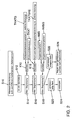
- FIG. 1 shows a multi-cylinder engine 10, downstream of which is a twin-flow exhaust gas purification system 12.
- two cylinders 14, 14 'of the multi-cylinder engine 10 are assigned to the two exhaust gas paths 16, 16' of the exhaust gas purification system 12.
- Each exhaust gas path 16, 16 ' has a precatalyst 18, 18', which is preceded by a lambda probe 20, 20 '.
- Downstream of the primary catalytic converters 18, 18 ', both exhaust gas paths 16, 16' are combined to form a single exhaust gas path 22, in which a main catalytic converter 24 is arranged.
- a lambda measuring device 26 Downstream of the main catalytic converter 24, in turn, there is a lambda measuring device 26, which may be formed by a lambda probe or a NO x sensor.
- a temperature sensor 28 for determining the exhaust gas temperature or the catalyst temperature is arranged upstream of the main catalytic converter 24, a temperature sensor 28 for determining the exhaust gas temperature or the catalyst temperature is arranged.
- An exhaust gas path 16 is supplied with lean and the second exhaust line 16 'is supplied with lean exhaust gas, wherein the lambda values of the two exhaust lines are preferably split such that after merging the two exhaust lines 16, 16' to a single exhaust line 22, a lambda value of about 1 is present, with which then the main catalyst 24 is applied.
- the signals emitted by the lambda probes 20, 20 ', the Lambdam measuring device 26 and the temperature sensor 28 are processed in a control device or engine control unit, not shown here.
- the inventive method is shown.
- a heat flow demand S10 resulting, for example, from the difference of the catalyst temperature TKAT and the target temperature of the main catalyst 24.
- the first limiting factor S14 is defined by a map K10, which is based on the catalyst temperature TKAT and the catalyst temperature gradient TKATG. Accordingly, the energy input is limited with increasing catalyst temperature TKAT, wherein the difference of the catalyst temperature TKAT to the target temperature is not taken into account.
- the catalyst temperature TKAT is also used and also the catalyst temperature gradient change TKATGAE.
- the split factor is limited at high positive temperature gradients in the main catalytic converter 24, in particular when already high temperatures TKAT are present in the main catalytic converter 24.
- the withdrawal of the split factor is all the more pronounced if, in addition, the positive temperature gradient TKATG has a progressive increase, in order to reliably avoid the risk of a "runaway" of the main catalytic converter 24.
- the split factor is limited depending on the exhaust gas mass flow AMS and the exhaust gas mass flow gradient AMSG using a third characteristic K16, since with reduced exhaust gas mass flow and its cooling effect decreases and there in operating situations that cause a high negative exhaust gas mass flow gradient, the HC and O 2 content in the exhaust gas and thus the chemical energy input increases rapidly for a short time.
Landscapes
- Engineering & Computer Science (AREA)
- Chemical & Material Sciences (AREA)
- Combustion & Propulsion (AREA)
- Mechanical Engineering (AREA)
- General Engineering & Computer Science (AREA)
- Chemical Kinetics & Catalysis (AREA)
- Exhaust Gas After Treatment (AREA)
- Electrical Control Of Air Or Fuel Supplied To Internal-Combustion Engine (AREA)
- Combined Controls Of Internal Combustion Engines (AREA)
Applications Claiming Priority (3)
| Application Number | Priority Date | Filing Date | Title |
|---|---|---|---|
| DE10261911 | 2002-12-30 | ||
| DE10261911A DE10261911A1 (de) | 2002-12-30 | 2002-12-30 | Verfahren zur Steuerung der Temperatur eines Katalysators sowie Mehrzylindermotor mit lambdasplitfähiger Abgasreinigungsanlage |
| PCT/EP2003/014156 WO2004059150A1 (de) | 2002-12-30 | 2003-12-12 | Verfahren zur steuerung der temperatur eines katalysators sowie mehrzylindermotor mit lambdasplitfähiger abgasreinigungsanlage |
Publications (2)
| Publication Number | Publication Date |
|---|---|
| EP1581733A1 EP1581733A1 (de) | 2005-10-05 |
| EP1581733B1 true EP1581733B1 (de) | 2006-06-07 |
Family
ID=32602452
Family Applications (1)
| Application Number | Title | Priority Date | Filing Date |
|---|---|---|---|
| EP03789253A Expired - Lifetime EP1581733B1 (de) | 2002-12-30 | 2003-12-12 | Verfahren zur steuerung der temperatur eines katalysators sowie mehrzylindermotor mit lambdasplitfähiger abgasreinigungsanlage |
Country Status (6)
| Country | Link |
|---|---|
| US (1) | US7356988B2 (enExample) |
| EP (1) | EP1581733B1 (enExample) |
| JP (1) | JP4332120B2 (enExample) |
| CN (1) | CN100422530C (enExample) |
| DE (2) | DE10261911A1 (enExample) |
| WO (1) | WO2004059150A1 (enExample) |
Families Citing this family (19)
| Publication number | Priority date | Publication date | Assignee | Title |
|---|---|---|---|---|
| DE102004043529B3 (de) * | 2004-09-08 | 2005-09-01 | Siemens Ag | Verfahren zur Gemischregelung einer Otto-Mehrzylinder-Brennkraftmaschine mit zylinderbezogenen Einzelkatalysatoren und einem den Einzelkatalysatoren nachgeschalteten gemeinsamen Hauptkatalysator |
| JP4997515B2 (ja) * | 2004-12-16 | 2012-08-08 | 独立行政法人産業技術総合研究所 | 化学物質の無害化反応プロセス |
| JP4817294B2 (ja) * | 2005-12-02 | 2011-11-16 | 独立行政法人産業技術総合研究所 | 窒素酸化物の選択的還元させる方法 |
| DE102006007417B4 (de) * | 2006-02-17 | 2012-08-09 | Continental Automotive Gmbh | Verfahren und Vorrichtung zum Betreiben einer Brennkraftmaschine |
| US7797929B2 (en) | 2007-05-21 | 2010-09-21 | Ford Global Technologies, Llc | Low temperature emission control |
| US7971430B2 (en) * | 2008-04-04 | 2011-07-05 | Ford Global Technologies, Llc | Diesel turbine SCR catalyst |
| US8186146B2 (en) * | 2008-08-27 | 2012-05-29 | Caterpillar Inc. | After-treatment component detection system |
| US8443587B2 (en) * | 2009-02-23 | 2013-05-21 | GM Global Technology Operations LLC | Method for exhaust aftertreatment in an internal combustion engine |
| DE102010027983B4 (de) * | 2010-04-20 | 2022-03-10 | Robert Bosch Gmbh | Verfahren zum Betreiben einer Brennkraftmaschine zum Abgleich einer Abgassonde |
| JP5269174B2 (ja) * | 2011-11-28 | 2013-08-21 | 株式会社豊田自動織機 | 内燃機関における排気ガス浄化装置 |
| DE102016202351A1 (de) | 2016-02-16 | 2017-08-17 | Volkswagen Aktiengesellschaft | Verfahren zum Betreiben einer Verbrennungskraftmaschine und Dreizylindermotor zum Ausführen eines solchen Verfahrens |
| DE102019004905A1 (de) | 2019-07-13 | 2021-01-14 | Man Truck & Bus Se | Verfahren und Vorrichtung zur Versorgung einer Wasserstoff-Brennkraftmaschine eines Kraftfahrzeugs mit Wasserstoff |
| US10871140B1 (en) | 2019-10-18 | 2020-12-22 | Ford Global Technologies, Llc | Systems and methods for reducing engine torque utilizing split lambda fueling |
| DE102019218427A1 (de) * | 2019-11-28 | 2021-06-02 | Robert Bosch Gmbh | Verfahren zur Diagnose von mehreren Lambdasonden |
| US11022061B1 (en) | 2020-01-31 | 2021-06-01 | Ford Global Technologies, Llc | Systems and methods for an exhaust gas temperature sensor diagnostics using split lambda engine operation |
| US11174805B2 (en) * | 2020-04-03 | 2021-11-16 | Ford Global Technologies, Llc | Split lambda fueling operation systems and methods |
| US11300063B2 (en) | 2020-07-20 | 2022-04-12 | Ford Global Technologies, Llc | Systems and methods for split lambda catalyst heating |
| EA202092385A1 (ru) * | 2020-07-24 | 2022-01-31 | Пауэрхаус Энджин Солюшнз Свитселанд АйПи Холдинг ГмбХ | Система двигателя внутреннего сгорания |
| DE102021111331A1 (de) | 2021-05-03 | 2022-11-03 | Volkswagen Aktiengesellschaft | Entschwefelung eines Dreiwegekatalysators einer Brennkraftmaschine |
Family Cites Families (29)
| Publication number | Priority date | Publication date | Assignee | Title |
|---|---|---|---|---|
| US4012906A (en) * | 1972-06-26 | 1977-03-22 | Nippon Soken, Inc. | Overheat preventing system for exhaust gas purifier of vehicles |
| JPS59150921A (ja) * | 1983-02-16 | 1984-08-29 | Toyota Motor Corp | デイ−ゼルエンジンの排気浄化装置におけるトラツプ再生装置 |
| DE4310145A1 (de) * | 1993-03-29 | 1994-04-07 | Daimler Benz Ag | Mehrzylindrige Brennkraftmaschine mit mindestens zwei Zylindergruppen |
| US6237330B1 (en) * | 1998-04-15 | 2001-05-29 | Nissan Motor Co., Ltd. | Exhaust purification device for internal combustion engine |
| US6651422B1 (en) * | 1998-08-24 | 2003-11-25 | Legare Joseph E. | Catalyst efficiency detection and heating method using cyclic fuel control |
| DE19852294A1 (de) | 1998-11-12 | 2000-05-18 | Bayerische Motoren Werke Ag | Abgasanlage einer Mehrzylinder-Brennkraftmaschine |
| AU4237300A (en) * | 1999-04-19 | 2000-11-02 | Engelhard Corporation | Catalyst composition comprising ceria and a platinum group metal |
| US6244043B1 (en) * | 1999-05-19 | 2001-06-12 | Ford Global Technologies, Inc. | Emission control device air/fuel ratio control system |
| US6354079B1 (en) * | 1999-11-26 | 2002-03-12 | Hyundai Motor Company | Apparatus and method of purifying NOx in the exhaust gas of the diesel engine |
| DE10005954A1 (de) * | 2000-02-09 | 2001-08-16 | Bosch Gmbh Robert | Entschwefelung eines Speicherkatalysators durch Aufheizen |
| DE60102874T2 (de) * | 2000-02-24 | 2004-09-02 | Nissan Motor Co., Ltd., Yokohama | Abgasreinigungsvorrichtung für brennkraftmaschine |
| DE10031874A1 (de) | 2000-06-30 | 2002-01-17 | Bosch Gmbh Robert | Vorrichtung zur Zündung einer bezindirekteinspritzenden Brennkraftmaschine und entsprechendes Verfahren |
| DE10034143A1 (de) | 2000-07-13 | 2002-02-07 | Volkswagen Ag | Verfahren zur Adaption eines Katalysatortemperatur-Sollbereichs für einen NOx-Speicherkatalysator |
| JP4492776B2 (ja) | 2000-09-05 | 2010-06-30 | 株式会社デンソー | 内燃機関の排気浄化装置 |
| JP2002148802A (ja) | 2000-11-07 | 2002-05-22 | Tokyo Ohka Kogyo Co Ltd | サンドブラスト用感光性組成物及びそれを用いた感光性フィルム |
| DE10055665A1 (de) * | 2000-11-10 | 2002-10-31 | Volkswagen Ag | Verfahren und Vorrichtung zur Katalysatorbeheizung |
| DE10057938A1 (de) | 2000-11-22 | 2002-05-23 | Volkswagen Ag | Verfahren und Vorrichtung zur Regeneration eines NOx-Speicherkatalysators |
| DE10112938A1 (de) | 2001-03-12 | 2002-10-02 | Volkswagen Ag | Verfahren zur Steuerung eines Warmlaufs eines Katalysatorsystems |
| JP3812353B2 (ja) * | 2001-03-19 | 2006-08-23 | 株式会社日立製作所 | 半導体電力変換装置 |
| JP3838339B2 (ja) * | 2001-03-27 | 2006-10-25 | 三菱ふそうトラック・バス株式会社 | 内燃機関の排気浄化装置 |
| DE10123148B4 (de) | 2001-05-03 | 2011-09-15 | Volkswagen Ag | Verfahren und Vorrichtung zur Entschwefelung eines Vorkatalysators |
| JP3879833B2 (ja) * | 2002-03-04 | 2007-02-14 | 三菱自動車工業株式会社 | 内燃機関の排気浄化装置 |
| DE10228659A1 (de) * | 2002-06-27 | 2004-01-22 | Daimlerchrysler Ag | Verfahren zur Überwachung einer Abgasanlage eines Kraftfahrzeuges |
| JP3969273B2 (ja) * | 2002-10-03 | 2007-09-05 | 株式会社デンソー | 内燃機関の排気浄化装置 |
| JP4140371B2 (ja) * | 2002-12-16 | 2008-08-27 | 日産自動車株式会社 | パティキュレートフィルタの再生装置及びエンジンの排気ガス浄化装置 |
| JP4464613B2 (ja) * | 2003-02-28 | 2010-05-19 | 三菱自動車工業株式会社 | 触媒温度推定装置及び触媒温度推定方法 |
| JP2005048678A (ja) * | 2003-07-30 | 2005-02-24 | Nissan Motor Co Ltd | 内燃機関の燃焼制御装置 |
| EP2014899B8 (en) * | 2003-11-12 | 2013-02-20 | Toyota Jidosha Kabushiki Kaisha | Fuel injection control apparatus and fuel injection control method for internal combustion engine |
| DE102004031321C5 (de) * | 2004-06-29 | 2020-06-25 | Robert Bosch Gmbh | Verfahren zum Dosieren eines Brennstoffs in einen Abgaskanal einer Brennkraftmaschine und Vorrichtung zur Durchführung des Verfahrens |
-
2002
- 2002-12-30 DE DE10261911A patent/DE10261911A1/de not_active Withdrawn
-
2003
- 2003-12-12 WO PCT/EP2003/014156 patent/WO2004059150A1/de not_active Ceased
- 2003-12-12 EP EP03789253A patent/EP1581733B1/de not_active Expired - Lifetime
- 2003-12-12 JP JP2004562741A patent/JP4332120B2/ja not_active Expired - Fee Related
- 2003-12-12 US US10/541,004 patent/US7356988B2/en not_active Expired - Fee Related
- 2003-12-12 DE DE50303755T patent/DE50303755D1/de not_active Expired - Lifetime
- 2003-12-12 CN CNB2003801075630A patent/CN100422530C/zh not_active Expired - Fee Related
Also Published As
| Publication number | Publication date |
|---|---|
| CN1732337A (zh) | 2006-02-08 |
| JP2006521482A (ja) | 2006-09-21 |
| JP4332120B2 (ja) | 2009-09-16 |
| DE50303755D1 (de) | 2006-07-20 |
| EP1581733A1 (de) | 2005-10-05 |
| US7356988B2 (en) | 2008-04-15 |
| WO2004059150A1 (de) | 2004-07-15 |
| DE10261911A1 (de) | 2004-07-29 |
| US20060080951A1 (en) | 2006-04-20 |
| CN100422530C (zh) | 2008-10-01 |
Similar Documents
| Publication | Publication Date | Title |
|---|---|---|
| EP1581733B1 (de) | Verfahren zur steuerung der temperatur eines katalysators sowie mehrzylindermotor mit lambdasplitfähiger abgasreinigungsanlage | |
| EP0892158B1 (de) | Verfahren und Vorrichtung zur Überwachung der De-Sulfatierung bei NOx-Speicherkatalysatoren | |
| EP3572634B1 (de) | Verfahren und vorrichtung zur abgasnachbehandlung eines verbrennungsmotors | |
| DE102011007364A1 (de) | Verfahren und Vorrichtung zur Regeneration eines Partikelfilters bei einem Y-Abgassystem | |
| EP1205648B1 (de) | Verfahren und Vorrichtung zur Katalysatorbeheizung | |
| EP1180201A1 (de) | Verfahren zur entschwefelung von einem in einem abgaskanal einer verbrennungskraftmaschine angeordneten nox-speicherkatalysator | |
| EP1132584B1 (de) | Verfahren und Vorrichtung zur Steuerung einer Heizmassnahme in einer Abgasreinigungsanlage von Brennkraftmaschinen | |
| DE10016219A1 (de) | Verfahren und Vorrichtung zur Steuerung einer Heizmaßnahme in einer Abgasreinigungsanlage von Brennkraftmaschinen | |
| DE10226873B4 (de) | Verfahren zur Steuerung der Betriebsartenwahl einer Verbrennungskraftmaschine | |
| DE10154041B4 (de) | Verfahren und Vorrichtung zur Reduzierung einer Schadstoffendemission | |
| EP1143131A2 (de) | Mehrflutige Abgasanlage und Verfahren zur Regelung eines Luft-Kraftstoff-Verhältnisses und Steuerung einer NOx-Regeneration eines NOx-Speicherkatalysators | |
| EP1179124A1 (de) | Verfahren zur entschwefelung | |
| DE102016210897B4 (de) | Steuerung einer Stickoxidemission in Betriebsphasen hoher Last | |
| EP1235977B1 (de) | Verfahren und vorrichtung zur steuerung einer aufheizphase zumindest eines in einem abgaskanal einer verbrennungskraftmaschine angeordneten katalysators | |
| EP1391592B1 (de) | Verfahren zum Betrieb eines magerlauffähigen Verbrennungsmotors mit einem Abgasreinigungssystem | |
| DE10130053B4 (de) | Verfahren und Vorrichtung zur Entschwefelung eines NOX-Speicherkatalysators | |
| EP1581729B1 (de) | Verfahren zur steuerung einer verbrennungskraftmaschine sowie magerlauffahige verbrennungskraftmaschine | |
| EP1108875B1 (de) | Verfahren zum Aufheizen eines Katalysators insbesondere im Leerlaufbetrieb eines magerlauffähigen Verbrennungsmotors eines Fahrzeugs | |
| DE102005063204B4 (de) | Auslegung und Betrieb einer magerlauffähigen Brennkraftmaschine mit angepasster Abgasnachbehandlung | |
| DE10230676B4 (de) | Verfahren zur thermischen Regeneration einer Abgasreinigungsvorrichtung sowie Verbrennungsmotoranlage | |
| EP1479894B1 (de) | Verfahren zum Betreiben einer Brennkraftmaschine | |
| EP1387070B1 (de) | Verfahren und Vorrichtung zum Betrieb einer Abgasnachbehandlungsanlage einer Verbrennungskraftmaschine | |
| DE10114523B4 (de) | Verfahren zur Steuerung einer NOx-Regeneration eines im Abgasstrang einer Verbrennungskraftmaschine angeordneten NOx-Speicherkatalysators | |
| EP1491749B1 (de) | Verfahren zum Betreiben einer Brennkraftmaschine | |
| EP1435444A2 (de) | Verfahren zum emissionsstabilen Betrieb eines Verbrennungsmotors sowie emissionsstabiles Kraftfahrzeug |
Legal Events
| Date | Code | Title | Description |
|---|---|---|---|
| PUAI | Public reference made under article 153(3) epc to a published international application that has entered the european phase |
Free format text: ORIGINAL CODE: 0009012 |
|
| 17P | Request for examination filed |
Effective date: 20050801 |
|
| AK | Designated contracting states |
Kind code of ref document: A1 Designated state(s): AT BE BG CH CY CZ DE DK EE ES FI FR GB GR HU IE IT LI LU MC NL PT RO SE SI SK TR |
|
| GRAP | Despatch of communication of intention to grant a patent |
Free format text: ORIGINAL CODE: EPIDOSNIGR1 |
|
| RBV | Designated contracting states (corrected) |
Designated state(s): DE ES FR GB |
|
| RIN1 | Information on inventor provided before grant (corrected) |
Inventor name: PHILIPP, KAI Inventor name: POTT, EKKEHARD Inventor name: BREE, ERIC |
|
| GRAS | Grant fee paid |
Free format text: ORIGINAL CODE: EPIDOSNIGR3 |
|
| GRAA | (expected) grant |
Free format text: ORIGINAL CODE: 0009210 |
|
| AK | Designated contracting states |
Kind code of ref document: B1 Designated state(s): DE ES FR GB |
|
| REG | Reference to a national code |
Ref country code: GB Ref legal event code: FG4D Free format text: NOT ENGLISH |
|
| REF | Corresponds to: |
Ref document number: 50303755 Country of ref document: DE Date of ref document: 20060720 Kind code of ref document: P |
|
| PG25 | Lapsed in a contracting state [announced via postgrant information from national office to epo] |
Ref country code: ES Free format text: LAPSE BECAUSE OF FAILURE TO SUBMIT A TRANSLATION OF THE DESCRIPTION OR TO PAY THE FEE WITHIN THE PRESCRIBED TIME-LIMIT Effective date: 20060918 |
|
| GBT | Gb: translation of ep patent filed (gb section 77(6)(a)/1977) |
Effective date: 20060923 |
|
| PLBE | No opposition filed within time limit |
Free format text: ORIGINAL CODE: 0009261 |
|
| STAA | Information on the status of an ep patent application or granted ep patent |
Free format text: STATUS: NO OPPOSITION FILED WITHIN TIME LIMIT |
|
| EN | Fr: translation not filed | ||
| 26N | No opposition filed |
Effective date: 20070308 |
|
| PG25 | Lapsed in a contracting state [announced via postgrant information from national office to epo] |
Ref country code: FR Free format text: LAPSE BECAUSE OF FAILURE TO SUBMIT A TRANSLATION OF THE DESCRIPTION OR TO PAY THE FEE WITHIN THE PRESCRIBED TIME-LIMIT Effective date: 20070309 |
|
| PG25 | Lapsed in a contracting state [announced via postgrant information from national office to epo] |
Ref country code: FR Free format text: LAPSE BECAUSE OF FAILURE TO SUBMIT A TRANSLATION OF THE DESCRIPTION OR TO PAY THE FEE WITHIN THE PRESCRIBED TIME-LIMIT Effective date: 20060607 |
|
| PGFP | Annual fee paid to national office [announced via postgrant information from national office to epo] |
Ref country code: DE Payment date: 20171231 Year of fee payment: 15 |
|
| PGFP | Annual fee paid to national office [announced via postgrant information from national office to epo] |
Ref country code: GB Payment date: 20181221 Year of fee payment: 16 |
|
| REG | Reference to a national code |
Ref country code: DE Ref legal event code: R119 Ref document number: 50303755 Country of ref document: DE |
|
| PG25 | Lapsed in a contracting state [announced via postgrant information from national office to epo] |
Ref country code: DE Free format text: LAPSE BECAUSE OF NON-PAYMENT OF DUE FEES Effective date: 20190702 |
|
| GBPC | Gb: european patent ceased through non-payment of renewal fee |
Effective date: 20191212 |
|
| PG25 | Lapsed in a contracting state [announced via postgrant information from national office to epo] |
Ref country code: GB Free format text: LAPSE BECAUSE OF NON-PAYMENT OF DUE FEES Effective date: 20191212 |