EP1581733B1 - Method for controlling the temperature of a catalyst and multicylinder engine comprising a lambda splitting exhaust gas cleaning system - Google Patents
Method for controlling the temperature of a catalyst and multicylinder engine comprising a lambda splitting exhaust gas cleaning system Download PDFInfo
- Publication number
- EP1581733B1 EP1581733B1 EP03789253A EP03789253A EP1581733B1 EP 1581733 B1 EP1581733 B1 EP 1581733B1 EP 03789253 A EP03789253 A EP 03789253A EP 03789253 A EP03789253 A EP 03789253A EP 1581733 B1 EP1581733 B1 EP 1581733B1
- Authority
- EP
- European Patent Office
- Prior art keywords
- exhaust gas
- catalytic converter
- temperature
- lambda
- energy
- Prior art date
- Legal status (The legal status is an assumption and is not a legal conclusion. Google has not performed a legal analysis and makes no representation as to the accuracy of the status listed.)
- Expired - Fee Related
Links
Images

Classifications
-
- F—MECHANICAL ENGINEERING; LIGHTING; HEATING; WEAPONS; BLASTING
- F02—COMBUSTION ENGINES; HOT-GAS OR COMBUSTION-PRODUCT ENGINE PLANTS
- F02D—CONTROLLING COMBUSTION ENGINES
- F02D41/00—Electrical control of supply of combustible mixture or its constituents
- F02D41/008—Controlling each cylinder individually
- F02D41/0082—Controlling each cylinder individually per groups or banks
-
- F—MECHANICAL ENGINEERING; LIGHTING; HEATING; WEAPONS; BLASTING
- F01—MACHINES OR ENGINES IN GENERAL; ENGINE PLANTS IN GENERAL; STEAM ENGINES
- F01N—GAS-FLOW SILENCERS OR EXHAUST APPARATUS FOR MACHINES OR ENGINES IN GENERAL; GAS-FLOW SILENCERS OR EXHAUST APPARATUS FOR INTERNAL COMBUSTION ENGINES
- F01N13/00—Exhaust or silencing apparatus characterised by constructional features ; Exhaust or silencing apparatus, or parts thereof, having pertinent characteristics not provided for in, or of interest apart from, groups F01N1/00 - F01N5/00, F01N9/00, F01N11/00
- F01N13/009—Exhaust or silencing apparatus characterised by constructional features ; Exhaust or silencing apparatus, or parts thereof, having pertinent characteristics not provided for in, or of interest apart from, groups F01N1/00 - F01N5/00, F01N9/00, F01N11/00 having two or more separate purifying devices arranged in series
-
- F—MECHANICAL ENGINEERING; LIGHTING; HEATING; WEAPONS; BLASTING
- F01—MACHINES OR ENGINES IN GENERAL; ENGINE PLANTS IN GENERAL; STEAM ENGINES
- F01N—GAS-FLOW SILENCERS OR EXHAUST APPARATUS FOR MACHINES OR ENGINES IN GENERAL; GAS-FLOW SILENCERS OR EXHAUST APPARATUS FOR INTERNAL COMBUSTION ENGINES
- F01N13/00—Exhaust or silencing apparatus characterised by constructional features ; Exhaust or silencing apparatus, or parts thereof, having pertinent characteristics not provided for in, or of interest apart from, groups F01N1/00 - F01N5/00, F01N9/00, F01N11/00
- F01N13/011—Exhaust or silencing apparatus characterised by constructional features ; Exhaust or silencing apparatus, or parts thereof, having pertinent characteristics not provided for in, or of interest apart from, groups F01N1/00 - F01N5/00, F01N9/00, F01N11/00 having two or more purifying devices arranged in parallel
-
- F—MECHANICAL ENGINEERING; LIGHTING; HEATING; WEAPONS; BLASTING
- F01—MACHINES OR ENGINES IN GENERAL; ENGINE PLANTS IN GENERAL; STEAM ENGINES
- F01N—GAS-FLOW SILENCERS OR EXHAUST APPARATUS FOR MACHINES OR ENGINES IN GENERAL; GAS-FLOW SILENCERS OR EXHAUST APPARATUS FOR INTERNAL COMBUSTION ENGINES
- F01N3/00—Exhaust or silencing apparatus having means for purifying, rendering innocuous, or otherwise treating exhaust
- F01N3/08—Exhaust or silencing apparatus having means for purifying, rendering innocuous, or otherwise treating exhaust for rendering innocuous
- F01N3/0807—Exhaust or silencing apparatus having means for purifying, rendering innocuous, or otherwise treating exhaust for rendering innocuous by using absorbents or adsorbents
- F01N3/0814—Exhaust or silencing apparatus having means for purifying, rendering innocuous, or otherwise treating exhaust for rendering innocuous by using absorbents or adsorbents combined with catalytic converters, e.g. NOx absorption/storage reduction catalysts
-
- F—MECHANICAL ENGINEERING; LIGHTING; HEATING; WEAPONS; BLASTING
- F01—MACHINES OR ENGINES IN GENERAL; ENGINE PLANTS IN GENERAL; STEAM ENGINES
- F01N—GAS-FLOW SILENCERS OR EXHAUST APPARATUS FOR MACHINES OR ENGINES IN GENERAL; GAS-FLOW SILENCERS OR EXHAUST APPARATUS FOR INTERNAL COMBUSTION ENGINES
- F01N3/00—Exhaust or silencing apparatus having means for purifying, rendering innocuous, or otherwise treating exhaust
- F01N3/08—Exhaust or silencing apparatus having means for purifying, rendering innocuous, or otherwise treating exhaust for rendering innocuous
- F01N3/0807—Exhaust or silencing apparatus having means for purifying, rendering innocuous, or otherwise treating exhaust for rendering innocuous by using absorbents or adsorbents
- F01N3/0828—Exhaust or silencing apparatus having means for purifying, rendering innocuous, or otherwise treating exhaust for rendering innocuous by using absorbents or adsorbents characterised by the absorbed or adsorbed substances
- F01N3/0842—Nitrogen oxides
-
- F—MECHANICAL ENGINEERING; LIGHTING; HEATING; WEAPONS; BLASTING
- F02—COMBUSTION ENGINES; HOT-GAS OR COMBUSTION-PRODUCT ENGINE PLANTS
- F02D—CONTROLLING COMBUSTION ENGINES
- F02D41/00—Electrical control of supply of combustible mixture or its constituents
- F02D41/02—Circuit arrangements for generating control signals
- F02D41/021—Introducing corrections for particular conditions exterior to the engine
- F02D41/0235—Introducing corrections for particular conditions exterior to the engine in relation with the state of the exhaust gas treating apparatus
- F02D41/024—Introducing corrections for particular conditions exterior to the engine in relation with the state of the exhaust gas treating apparatus to increase temperature of the exhaust gas treating apparatus
- F02D41/025—Introducing corrections for particular conditions exterior to the engine in relation with the state of the exhaust gas treating apparatus to increase temperature of the exhaust gas treating apparatus by changing the composition of the exhaust gas, e.g. for exothermic reaction on exhaust gas treating apparatus
-
- F—MECHANICAL ENGINEERING; LIGHTING; HEATING; WEAPONS; BLASTING
- F02—COMBUSTION ENGINES; HOT-GAS OR COMBUSTION-PRODUCT ENGINE PLANTS
- F02D—CONTROLLING COMBUSTION ENGINES
- F02D41/00—Electrical control of supply of combustible mixture or its constituents
- F02D41/02—Circuit arrangements for generating control signals
- F02D41/14—Introducing closed-loop corrections
- F02D41/1438—Introducing closed-loop corrections using means for determining characteristics of the combustion gases; Sensors therefor
- F02D41/1439—Introducing closed-loop corrections using means for determining characteristics of the combustion gases; Sensors therefor characterised by the position of the sensor
- F02D41/1441—Plural sensors
- F02D41/1443—Plural sensors with one sensor per cylinder or group of cylinders
-
- F—MECHANICAL ENGINEERING; LIGHTING; HEATING; WEAPONS; BLASTING
- F02—COMBUSTION ENGINES; HOT-GAS OR COMBUSTION-PRODUCT ENGINE PLANTS
- F02D—CONTROLLING COMBUSTION ENGINES
- F02D41/00—Electrical control of supply of combustible mixture or its constituents
- F02D41/02—Circuit arrangements for generating control signals
- F02D41/14—Introducing closed-loop corrections
- F02D41/1438—Introducing closed-loop corrections using means for determining characteristics of the combustion gases; Sensors therefor
- F02D41/1473—Introducing closed-loop corrections using means for determining characteristics of the combustion gases; Sensors therefor characterised by the regulation method
- F02D41/1475—Regulating the air fuel ratio at a value other than stoichiometry
-
- F—MECHANICAL ENGINEERING; LIGHTING; HEATING; WEAPONS; BLASTING
- F02—COMBUSTION ENGINES; HOT-GAS OR COMBUSTION-PRODUCT ENGINE PLANTS
- F02D—CONTROLLING COMBUSTION ENGINES
- F02D2200/00—Input parameters for engine control
- F02D2200/02—Input parameters for engine control the parameters being related to the engine
- F02D2200/08—Exhaust gas treatment apparatus parameters
- F02D2200/0802—Temperature of the exhaust gas treatment apparatus
-
- F—MECHANICAL ENGINEERING; LIGHTING; HEATING; WEAPONS; BLASTING
- F02—COMBUSTION ENGINES; HOT-GAS OR COMBUSTION-PRODUCT ENGINE PLANTS
- F02D—CONTROLLING COMBUSTION ENGINES
- F02D41/00—Electrical control of supply of combustible mixture or its constituents
- F02D41/02—Circuit arrangements for generating control signals
- F02D41/021—Introducing corrections for particular conditions exterior to the engine
- F02D41/0235—Introducing corrections for particular conditions exterior to the engine in relation with the state of the exhaust gas treating apparatus
- F02D41/027—Introducing corrections for particular conditions exterior to the engine in relation with the state of the exhaust gas treating apparatus to purge or regenerate the exhaust gas treating apparatus
- F02D41/0275—Introducing corrections for particular conditions exterior to the engine in relation with the state of the exhaust gas treating apparatus to purge or regenerate the exhaust gas treating apparatus the exhaust gas treating apparatus being a NOx trap or adsorbent
-
- F—MECHANICAL ENGINEERING; LIGHTING; HEATING; WEAPONS; BLASTING
- F02—COMBUSTION ENGINES; HOT-GAS OR COMBUSTION-PRODUCT ENGINE PLANTS
- F02D—CONTROLLING COMBUSTION ENGINES
- F02D41/00—Electrical control of supply of combustible mixture or its constituents
- F02D41/02—Circuit arrangements for generating control signals
- F02D41/14—Introducing closed-loop corrections
- F02D41/1438—Introducing closed-loop corrections using means for determining characteristics of the combustion gases; Sensors therefor
- F02D41/1444—Introducing closed-loop corrections using means for determining characteristics of the combustion gases; Sensors therefor characterised by the characteristics of the combustion gases
- F02D41/1446—Introducing closed-loop corrections using means for determining characteristics of the combustion gases; Sensors therefor characterised by the characteristics of the combustion gases the characteristics being exhaust temperatures
-
- Y—GENERAL TAGGING OF NEW TECHNOLOGICAL DEVELOPMENTS; GENERAL TAGGING OF CROSS-SECTIONAL TECHNOLOGIES SPANNING OVER SEVERAL SECTIONS OF THE IPC; TECHNICAL SUBJECTS COVERED BY FORMER USPC CROSS-REFERENCE ART COLLECTIONS [XRACs] AND DIGESTS
- Y02—TECHNOLOGIES OR APPLICATIONS FOR MITIGATION OR ADAPTATION AGAINST CLIMATE CHANGE
- Y02T—CLIMATE CHANGE MITIGATION TECHNOLOGIES RELATED TO TRANSPORTATION
- Y02T10/00—Road transport of goods or passengers
- Y02T10/10—Internal combustion engine [ICE] based vehicles
- Y02T10/12—Improving ICE efficiencies
Definitions
- the invention relates to a method for controlling the temperature of at least one catalyst arranged in an exhaust gas purification system of a lean-running multi-cylinder engine, in which energy can be introduced by means of a lambda split into the exhaust gas purification system, and a corresponding multi-cylinder engine with a lambda-spillable exhaust gas purification system.
- the exhaust gas is passed over at least one catalyst, which performs a conversion of one or more pollutant components of the exhaust gas.
- catalysts which performs a conversion of one or more pollutant components of the exhaust gas.
- Oxidation catalysts promote the oxidation of unburned hydrocarbons (HC) and carbon monoxide (CO), while reduction catalysts promote the reduction of nitrogen oxides (NO x ) of the exhaust gas.
- 3-way catalysts are used to simultaneously catalyze the conversion of the three aforementioned components (HC, CO, NO x ).
- storage catalysts for example NO x storage catalysts. These are used in the exhaust gas purification of internal combustion engines, which are operated for reasons of consumption optimization at least temporarily in a lean operating mode, that is, with an oxygen-rich exhaust gas with ⁇ > 1, with a high level of nitrogen oxides NO x arise.
- the nitrogen oxides NOx can not be completely converted to environmentally neutral nitrogen in a catalytic oxidative conversion of unburned hydrocarbons HC and carbon monoxide CO nitrogen oxides NO x .
- NO x storage catalytic converters are arranged in the exhaust ducts of internal combustion engines, which store in lean operating phases NO x as nitrate.
- the NO x storage catalytic converter must be regenerated at recurring intervals by switching to a rich or substoichiometric operation ( ⁇ ⁇ 1) of the internal combustion engine.
- the above-mentioned catalysts age by being exposed to high temperatures, so that the peak conversion rate decreases with respect to an undamaged catalyst.
- the maximum allowable temperature in the exhaust system is monitored and limited by adjusting engine operating parameters, preferably the combustion lambda.
- the heating of catalysts is particularly problematic when using pre- and main catalysts, since in the effort to bring the main catalyst to the desired temperature, the pre-catalysts can be thermally overloaded.
- the heating of the catalyst in particular a main catalyst, carried out such that the catalyst is simultaneously subjected to lean and rich exhaust gas.
- the exhaust gas in one of the two impinging paths is shifted by a predetermined amount in the direction of "rich” and in the other path in a corresponding manner in the opposite direction.
- the advantage of this measure is that the mixed exhaust gas before the catalyst simultaneously contains high oxygen and pollutant concentrations.
- the catalyst undergoes a high conversion of chemically bound energy. Since the energy required for catalyst heating is first converted to heat on the catalyst, the thermal losses on the way through the non-adiabatic exhaust system are eliminated.
- any existing pre-catalysts are not thermally overloaded, so that their lifetime stability increases significantly.
- a method for controlling the temperature of a catalyst arranged in an exhaust gas purification system of a lean-running multi-cylinder engine, in which energy can be introduced by means of a lambda split into the exhaust gas purification system, the height or a limitation of the energy input depending on at least one of the parameters catalyst temperature, exhaust gas temperature and Exhaust gas mass flow and / or as a function of at least one of the parameters change in the catalyst temperature, the exhaust gas temperature and the exhaust gas mass flow (1st derivative) and / or depending on at least one of the parameters rate of change of the catalyst temperature, the exhaust gas temperature and the exhaust gas mass flow (2nd derivative) ,
- the lambda-spitable exhaust gas purification system is configured such that between the multi-cylinder engine and the at least one catalyst are at least two passages or exhaust paths are located, which are each acted upon by a predetermined lambda, wherein it is particularly preferred that the emission control system at least one main catalyst whose temperature according to the method control, and has at least two upstream precatalysts, each precatalyst is arranged in a separate exhaust path.
- the control of the chemical energy input preferably takes place by limiting the split factor.
- This is understood here as a measure of enrichment in one of the exhaust paths.
- a request for energy input into the emission control system depending on the current catalyst temperature or the difference of the current catalyst temperature is defined by a predetermined target temperature. Normally, a rapid heating of the catalyst to the target temperature is desired, so that high energy inputs into the exhaust system and thus a high basic split factor are required.
- a mixed lambda setpoint of 1.0 is required.
- the risk of catalyst overloading increases, so that the limitation of the energy input according to the invention for controlling the temperature of the catalyst is of particular advantage.
- the convertible on the catalyst chemical energy fraction of the exhaust gas is determined by the available reducing agent and oxygen mass flow. Therefore, at Regulation of a lambda setpoint before the catalyst preferably the lambda in the lean path to the resulting from the required split factor lean lambda value as a function of the measured lambda before or after the main catalyst controlled while the rich path is piloted. This prevents problems with control by a probe usually arranged behind the catalyst due to measurement errors at the lambda probe behind the rich-path precatalyst, for example due to hydrogen cross-sensitivity.
- the process according to the invention is preferably used in NO x storage catalysts with optionally upstream pre-catalysts for desulfurization.
- the lean burnable multi-cylinder engine according to the invention with a lambda-spillable exhaust gas purification system, in which at least one catalyst is arranged, has means according to the invention with which, depending on at least one of the parameters catalyst temperature, exhaust gas temperature and exhaust gas mass flow and / or depending on at least one of the parameter change in the catalyst temperature, the exhaust gas temperature and the exhaust gas inlet flow (1st derivative) and / or as a function of at least one of the parameters change rate of the catalyst temperature, the exhaust gas temperature and the exhaust gas mass flow (2nd derivative) exhaust gas-relevant measures for controlling the temperature of the at least one catalyst by influencing at least one operating parameter , preferably the lambda value the multi-cylinder engine can be taken.
- the lambda-spitable exhaust gas purification system of the multi-cylinder engine is preferably designed such that at least two passages or exhaust gas paths are located between the multi-cylinder engine and the at least one catalytic converter, each of which can be acted upon by a predeterminable lambda.
- the emission control system has at least one main catalyst with at least two upstream pre-catalysts, which are each arranged in a separate exhaust path, each exhaust path can be acted upon separately with a predetermined lambda.
- control unit in which is preferably integrated in an engine control unit, in which models and algorithms for the coordinated control of exhaust gas and performance-relevant measures are stored in digitized form.
- the multi-cylinder engine according to the invention is a gasoline engine, in particular a directly injecting gasoline engine, or a diesel engine.
- the exhaust gas purification system or the at least one catalytic converter of the exhaust gas purification system of the multi-cylinder engine according to the invention has a reduced noble metal content.
- a significant reduction of the noble metal content over the prior art is possible.
- the noble metal content of at least one or the precatalyst (s) can be ⁇ 3.59 g / dm 3 (100 g / ft 3 ) and more preferably ⁇ 2.87 g / dm 3 (80 g / ft 3 ). be lowered.
- FIG. 1 shows a multi-cylinder engine 10, downstream of which is a twin-flow exhaust gas purification system 12.
- two cylinders 14, 14 'of the multi-cylinder engine 10 are assigned to the two exhaust gas paths 16, 16' of the exhaust gas purification system 12.
- Each exhaust gas path 16, 16 ' has a precatalyst 18, 18', which is preceded by a lambda probe 20, 20 '.
- Downstream of the primary catalytic converters 18, 18 ', both exhaust gas paths 16, 16' are combined to form a single exhaust gas path 22, in which a main catalytic converter 24 is arranged.
- a lambda measuring device 26 Downstream of the main catalytic converter 24, in turn, there is a lambda measuring device 26, which may be formed by a lambda probe or a NO x sensor.
- a temperature sensor 28 for determining the exhaust gas temperature or the catalyst temperature is arranged upstream of the main catalytic converter 24, a temperature sensor 28 for determining the exhaust gas temperature or the catalyst temperature is arranged.
- An exhaust gas path 16 is supplied with lean and the second exhaust line 16 'is supplied with lean exhaust gas, wherein the lambda values of the two exhaust lines are preferably split such that after merging the two exhaust lines 16, 16' to a single exhaust line 22, a lambda value of about 1 is present, with which then the main catalyst 24 is applied.
- the signals emitted by the lambda probes 20, 20 ', the Lambdam measuring device 26 and the temperature sensor 28 are processed in a control device or engine control unit, not shown here.
- the inventive method is shown.
- a heat flow demand S10 resulting, for example, from the difference of the catalyst temperature TKAT and the target temperature of the main catalyst 24.
- the first limiting factor S14 is defined by a map K10, which is based on the catalyst temperature TKAT and the catalyst temperature gradient TKATG. Accordingly, the energy input is limited with increasing catalyst temperature TKAT, wherein the difference of the catalyst temperature TKAT to the target temperature is not taken into account.
- the catalyst temperature TKAT is also used and also the catalyst temperature gradient change TKATGAE.
- the split factor is limited at high positive temperature gradients in the main catalytic converter 24, in particular when already high temperatures TKAT are present in the main catalytic converter 24.
- the withdrawal of the split factor is all the more pronounced if, in addition, the positive temperature gradient TKATG has a progressive increase, in order to reliably avoid the risk of a "runaway" of the main catalytic converter 24.
- the split factor is limited depending on the exhaust gas mass flow AMS and the exhaust gas mass flow gradient AMSG using a third characteristic K16, since with reduced exhaust gas mass flow and its cooling effect decreases and there in operating situations that cause a high negative exhaust gas mass flow gradient, the HC and O 2 content in the exhaust gas and thus the chemical energy input increases rapidly for a short time.
Abstract
Description
Die Erfindung betrifft ein Verfahren zur Steuerung der Temperatur zumindest eines in einer Abgasreinigungsanlage eines magerlauffähigen Mehrzylindermotors angeordneten Katalysators, bei dem Energie mittels eines Lambdasplits in die Abgasreinigungsanlage einbringbar ist, sowie einen entsprechenden Mehrzylindermotor mit einer lambdasplitfähigen Abgasreinigungsanlage.The invention relates to a method for controlling the temperature of at least one catalyst arranged in an exhaust gas purification system of a lean-running multi-cylinder engine, in which energy can be introduced by means of a lambda split into the exhaust gas purification system, and a corresponding multi-cylinder engine with a lambda-spillable exhaust gas purification system.
Zur Nachbehandlung von Abgasen von Verbrennungskraftmaschinen ist es allgemein üblich, diese katalytisch zu reinigen. Dazu wird das Abgas über mindestens einen Katalysator geleitet, der eine Konvertierung einer oder mehrerer Schadstoffkomponenten des Abgases vornimmt. Es sind unterschiedliche Arten von Katalysatoren bekannt. Oxidationskatalysatoren fördern die Oxidation von unverbrannten Kohlenwasserstoffen (HC) und Kohlenmonoxid (CO), während Reduktionskatalysatoren eine Reduzierung von Stickoxiden (NOx) des Abgases unterstützen. Zudem werden 3-Wege-Katalysatoren verwendet, um die Konvertierung der drei vorgenannten Komponenten (HC, CO, NOx) gleichzeitig zu katalysieren.For the aftertreatment of exhaust gases of internal combustion engines, it is common practice to purify them catalytically. For this purpose, the exhaust gas is passed over at least one catalyst, which performs a conversion of one or more pollutant components of the exhaust gas. Different types of catalysts are known. Oxidation catalysts promote the oxidation of unburned hydrocarbons (HC) and carbon monoxide (CO), while reduction catalysts promote the reduction of nitrogen oxides (NO x ) of the exhaust gas. In addition, 3-way catalysts are used to simultaneously catalyze the conversion of the three aforementioned components (HC, CO, NO x ).
Daneben sind auch Speicherkatalysatoren, beispielsweise NOx-Speicherkatalysatoren, bekannt. Diese werden bei der Abgasreinigung von Verbrennungskraftmaschinen eingesetzt, die aus Gründen einer Verbrauchsoptimierung wenigstens zeitweise in einem mageren Betriebsmodus, das heißt mit einem sauerstoffreichen Abgas mit λ > 1, betrieben werden, wobei in hohem Maße Stickoxide NOx entstehen. Die Stickoxide NOx können bei einer katalytischen oxidativen Umsetzung von unverbrannten Kohlenwasserstoffen HC und Kohlenmonoxid CO Stickoxide NOx nicht vollständig zu umweltneutralem Stickstoff umgesetzt werden. Zur Abhilfe werden vorgenannte NOx-Speicherkatalysatoren in den Abgaskanälen von Verbrennungskraftmaschinen angeordnet, die in mageren Betriebsphasen NOx als Nitrat einlagern. Der NOx-Speicherkatalysator muss in wiederkehrenden Abständen durch Umschaltung in einen fetten oder unterstöchiometrischen Betrieb (λ ≤ 1) der Verbrennungskraftmaschine regeneriert werden.In addition, storage catalysts, for example NO x storage catalysts, are known. These are used in the exhaust gas purification of internal combustion engines, which are operated for reasons of consumption optimization at least temporarily in a lean operating mode, that is, with an oxygen-rich exhaust gas with λ> 1, with a high level of nitrogen oxides NO x arise. The nitrogen oxides NOx can not be completely converted to environmentally neutral nitrogen in a catalytic oxidative conversion of unburned hydrocarbons HC and carbon monoxide CO nitrogen oxides NO x . To remedy the aforementioned NO x storage catalytic converters are arranged in the exhaust ducts of internal combustion engines, which store in lean operating phases NO x as nitrate. The NO x storage catalytic converter must be regenerated at recurring intervals by switching to a rich or substoichiometric operation (λ ≦ 1) of the internal combustion engine.
Vorgenannte Katalysatoren altern durch die Beaufschlagung mit hohen Temperaturen, so dass die Spitzen-Konvertierungsrate gegenüber einem ungeschädigten Katalysator abnimmt. Zur Minderung der Katalysatoralterung wird die maximal zulässige Temperatur im Abgassystem überwacht und durch Einstellung von Motorbetriebsparametern, vorzugsweise des Verbrennungslambdas, begrenzt.The above-mentioned catalysts age by being exposed to high temperatures, so that the peak conversion rate decreases with respect to an undamaged catalyst. To reduce catalyst aging, the maximum allowable temperature in the exhaust system is monitored and limited by adjusting engine operating parameters, preferably the combustion lambda.
Auf der anderen Seite ist es notwendig, eine Katalysatorheizung, das heißt einen Energieeintrag in die Abgasanlage vorzunehmen, um das optimale Temperaturfenster des Katalysators zu erreichen oder um bei NOx-Speicherkatalysatoren eine Entschwefelung durchzuführen, da diese durch den im Kraftstoff enthaltenen Schwefel vergiftet werden. Durch das Katalysatorheizen wird der NOx-Speicherkatalysator von eingelagertem Schwefel befreit. Für die Desorption des in Form von Sulfat eingelagerten Schwefels bedarf es einer Mindest-Temperatur, die bei zirka 600 °C liegt.On the other hand, it is necessary to carry out a catalyst heating, that is to say an energy input into the exhaust system in order to achieve the optimum temperature window of the catalytic converter or to desulphurise in the case of NO x storage catalytic converters, since these are poisoned by the sulfur contained in the fuel. By the catalyst heating of the NO x storage catalyst is freed from embedded sulfur. For the desorption of sulfur stored in the form of sulphate, a minimum temperature of about 600 ° C is required.
Das Heizen von Katalysatoren ist insbesondere bei der Verwendung von Vor- und Hauptkatalysatoren problematisch, da bei dem Bestreben, den Hauptkatalysator auf die gewünschte Temperatur zu bringen, die Vorkatalysatoren thermisch überlastet werden können.The heating of catalysts is particularly problematic when using pre- and main catalysts, since in the effort to bring the main catalyst to the desired temperature, the pre-catalysts can be thermally overloaded.
Um einen Energieeintrag in die Abgasreinigungsanlage zielgerichtet zu gestalten, vorzugsweise zur Entschwefelung von NOx-Speicherkatatysatoren, kann das Heizen des Katalysators, insbesondere eines Hauptkatalysators, derart erfolgen, dass der Katalysator gleichzeitig mit magerem und fettem Abgas beaufschlagt wird. So wird beispielsweise bei einem gewünschten Abgaslambda vor dem Hauptkatalysator von 1,0 das Abgas in einem der beiden beaufschlagenden Pfade um einen vorgegebenen Betrag in Richtung "fett" verschoben und in dem anderen Pfad in entsprechender Weise in die entgegengesetzte Richtung. Vorteil dieser Maßnahme ist, dass das Mischabgas vor dem Katalysator gleichzeitig hohe Sauerstoff- und Schadstoffkonzentrationen enthält. Dadurch erfolgt am Katalysator eine hohe Umsetzung chemisch gebundener Energie. Da die zur Katalysatorerwärmung benötigte Energie erst auf dem Katalysator in Wärme umgewandelt wird, entfallen die thermischen Verluste auf dem Weg durch die nicht-adiabatische Abgasanlage. Zudem werden die gegebenenfalls vorhandenen Vorkatalysatoren nicht thermisch überlastet, so dass sich deren Lebensdauersicherheit erheblich erhöht.In order to design a targeted energy input into the exhaust gas purification system, preferably for the desulfurization of NO x storage, the heating of the catalyst, in particular a main catalyst, carried out such that the catalyst is simultaneously subjected to lean and rich exhaust gas. Thus, for example, with a desired exhaust lambda before the main catalyst of 1.0, the exhaust gas in one of the two impinging paths is shifted by a predetermined amount in the direction of "rich" and in the other path in a corresponding manner in the opposite direction. The advantage of this measure is that the mixed exhaust gas before the catalyst simultaneously contains high oxygen and pollutant concentrations. As a result, the catalyst undergoes a high conversion of chemically bound energy. Since the energy required for catalyst heating is first converted to heat on the catalyst, the thermal losses on the way through the non-adiabatic exhaust system are eliminated. In addition, any existing pre-catalysts are not thermally overloaded, so that their lifetime stability increases significantly.
Problematisch bei dieser Verfahrensweise ist, dass die Gefahr einer Überlastung des Hauptkatalysators steigt, da infolge starker kataiytischer, Aktivität durch einen hohen chemischen Energieumsatz am Hauptkatalysator zumindest eine lokale thermische Überlastung nicht ausgeschlossen werden kann. Zudem kann ein Katalysator nur mittels Lambdasplit geheizt werden, wenn dieser zumindest teilweise aktiv, das heißt erwärmt ist, da für den chemischen Energieeintrag dessen Aktivität Voraussetzung ist.The problem with this procedure is that the risk of overloading the main catalyst increases, as a result of strong kataiytischer, activity by a high chemical energy conversion at the main catalyst at least one local thermal Overload can not be excluded. In addition, a catalyst can only be heated by means of lambda split, if this is at least partially active, that is heated, since its activity is a prerequisite for the chemical energy input.
Es ist daher Aufgabe der Erfindung, ein Verfahren zur Steuerung der Temperatur eines in einer Abgasreinigungsanlage eines magerlauffähigen Mehrzylindermotors angeordneten Katalysators, bei dem Energie mittels eines Lambdasplits in die Abgasreinigungsanlageanlage eingetragen wird, sowie einen entsprechenden magerlauffähigen Mehrzylindermotor mit lambdasplitfähiger Abgasreinigungsanlage zu schaffen, bei dem die Gefahr einer thermischen Überlastung des Katalysators sicher vermieden wird.It is therefore an object of the invention to provide a method for controlling the temperature of a arranged in an exhaust gas purification system of a lean-running multi-cylinder engine, in which energy is registered by a lambda split in the exhaust gas purification plant, and to create a corresponding lean-running multi-cylinder engine with lambdasplitfähiger emission control system, in which the risk a thermal overload of the catalyst is reliably avoided.
Diese Aufgabe wird durch ein Verfahren mit den im Anspruch 1 genannten Merkmalen sowie einen Mehrzylindermotor mit den in Anspruch 13 genannten Merkmalen gelöst.This object is achieved by a method having the features mentioned in
Erfindungsgemäß ist ein Verfahren zur Steuerung der Temperatur eines in einer Abgasreinigungsanlage eines magerlauffähigen Mehrzylindermotors angeordneten Katalysators vorgesehen, bei dem Energie mittels eines Lambdasplits in die Abgasreinigungsanlage einbringbar ist, wobei die Höhe beziehungsweise eine Begrenzung des Energieeintrages in Abhängigkeit von mindestens einem der Parameter Katalysatortemperatur, Abgastemperatur und Abgasmassenstrom und/oder in Abhängigkeit von mindestens einem der Parameter Änderung der Katalysatortemperatur, der Abgastemperatur und des Abgasmassenstromes (1. Ableitung) und/oder in Abhängigkeit von mindestens einem der Parameter Änderungsgeschwindigkeit der Katalysatortemperatur, der Abgastemperatur und des Abgasmassenstromes (2. Ableitung) erfolgt.According to the invention, a method is provided for controlling the temperature of a catalyst arranged in an exhaust gas purification system of a lean-running multi-cylinder engine, in which energy can be introduced by means of a lambda split into the exhaust gas purification system, the height or a limitation of the energy input depending on at least one of the parameters catalyst temperature, exhaust gas temperature and Exhaust gas mass flow and / or as a function of at least one of the parameters change in the catalyst temperature, the exhaust gas temperature and the exhaust gas mass flow (1st derivative) and / or depending on at least one of the parameters rate of change of the catalyst temperature, the exhaust gas temperature and the exhaust gas mass flow (2nd derivative) ,
Vorzugsweise ist die lambdasplitfähige Abgasreinigungsanlage derart ausgestaltet, dass zwischen dem Mehrzylindermotor und dem zumindest einen Katalysator mindestens zwei Passagen beziehungsweise Abgaspfade befindlich sind, die jeweils mit einem vorgebbaren Lambda beaufschlagbar sind, wobei besonders bevorzugt ist, dass die Abgasreinigungsanlage mindestens einen Hauptkatalysator, dessen Temperatur verfahrensgemäß zu steuern ist, und mindestens zwei vorgeordnete Vorkatalysatoren aufweist, wobei jeder Vorkatalysator in einem eigenen Abgaspfad angeordnet ist.Preferably, the lambda-spitable exhaust gas purification system is configured such that between the multi-cylinder engine and the at least one catalyst are at least two passages or exhaust paths are located, which are each acted upon by a predetermined lambda, wherein it is particularly preferred that the emission control system at least one main catalyst whose temperature according to the method control, and has at least two upstream precatalysts, each precatalyst is arranged in a separate exhaust path.
Vorzugsweise erfolgt die Steuerung des chemischen Energieeintrages durch Begrenzung des Splitfaktors. Dieser wird hier als Maß der Anfettung in einem der Abgaspfade verstanden. Ein Splitfaktor von 25 % bei einem Mischlambda-Sollwert von 1,0 bedeutet somit, dass bei einem 4-Zylinder-Motor zwei Zylinder mit Lambda = 0,75 betrieben werden und zwei Zylinder mit Lambda = 1,5. Bei einer Anforderung zum Heizen des Katalysators wird eine Anforderung zum Energieeintrag in die Abgasreinigungsanlage in Abhängigkeit von der aktuellen Katalysatortemperatur oder der Differenz der aktuellen Katalysatortemperatur von einer vorgebbaren Zieltemperatur definiert. Normalerweise ist ein schnelles Aufheizen des Katalysators auf die Zieltemperatur erwünscht, so dass hohe Energieeinträge in die Abgasanlage und damit ein hoher Grund-Splitfaktor gefordert werden. Um optimale Konvertierungsraten zu erzielen, wird ein Mischlambda-Sollwert von 1,0 gefordert. Bei einem hohen chemischen Anteil am Heizvorgang steigt jedoch im Gegensatz zu den überwiegend thermischen Heizverfahren nach dem Stand der Technik das Risiko einer Katalysatorüberlastung, so dass die erfindungsgemäße Begrenzung des Energieeintrages zur Steuerung der Temperatur des Katalysators von besonderem Vorteil ist.The control of the chemical energy input preferably takes place by limiting the split factor. This is understood here as a measure of enrichment in one of the exhaust paths. A split factor of 25% with a mixed lambda setpoint of 1.0 means Thus, in a 4-cylinder engine, two cylinders are operated with lambda = 0.75 and two cylinders with lambda = 1.5. In a request to heat the catalyst, a request for energy input into the emission control system depending on the current catalyst temperature or the difference of the current catalyst temperature is defined by a predetermined target temperature. Normally, a rapid heating of the catalyst to the target temperature is desired, so that high energy inputs into the exhaust system and thus a high basic split factor are required. To achieve optimal conversion rates, a mixed lambda setpoint of 1.0 is required. However, with a high chemical content of the heating process, in contrast to the predominantly thermal heating processes of the prior art, the risk of catalyst overloading increases, so that the limitation of the energy input according to the invention for controlling the temperature of the catalyst is of particular advantage.
Erfindungsgemäß erfolgt die Begrenzung des chemischen Energieeintrages beziehungsweise des Splitfaktors in Abhängigkeit vorgenannter Parameter bei:
- steigender gemessener oder modellierter Kätalysatortemperatur unabhängig von der Differenz zur Zieltemperatur, um Katalysatorschäden zu vermeiden, insbesondere wenn die Zieltemperatur nahe an der minimalen irreversiblen thermischen Schädigungstemperatur liegt,
- hohen positiven Temperaturgradienten im Hauptkatalysator, insbesondere bei hohen Temperaturen im Hauptkatalysator, zur Berücksichtigung eines inhomogenen Temperaturverlaufs im Hauptkatalysator, wobei die Begrenzung umso ausgeprägter ausfallen muss, wenn zusätzlich der positive Temperaturgradient eine progressive Zunahme aufweist, da hier das Risiko eines "Durchgehens" des Katalysators besonders hoch ist, und
- sinkendem Abgasmassenstrom, da der Kühleffekt des gegenüber der Katalysatortemperatur kühleren Abgasmassenstroms abnimmt, wobei bei hohen negativen Abgasmassenstromgradienten, beispielsweise bei einem Schaltvorgang, dem Übergang auf Niedriglast oder gefeuerten Schub, die Begrenzung stärker ausfallen soll, da HC- und O2-Gehalt im Abgas in diesen Betriebssituationen ohnehin kurzzeitig stark zunehmen.
- increasing measured or modeled Kätalysatortemperatur regardless of the difference to the target temperature to avoid catalyst damage, especially when the target temperature is close to the minimum irreversible thermal damage temperature,
- high temperature gradient in the main catalyst, especially at high temperatures in the main catalyst, to account for an inhomogeneous temperature profile in the main catalyst, the limitation must be more pronounced, in addition, the positive temperature gradient has a progressive increase, since the risk of a "runaway" of the catalyst particularly is high, and
- decreasing exhaust gas mass flow, since the cooling effect of compared to the catalyst temperature cooler exhaust gas mass decreases, with high negative Abgasmassenstromgradienten, for example, in a shift, the transition to low load or fired thrust, the limitation should be stronger, since HC and O 2 content in the exhaust gas in These operational situations increase rapidly for a short time anyway.
Der auf dem Katalysator umsetzbare chemische Energieanteil des Abgases wird durch den verfügbaren Reduktionsmittel- und Sauerstoffmassenstrom bestimmt. Daher wird bei Regelung auf einen Lambda-Sollwert vor dem Katalysator vorzugsweise das Lambda im mageren Pfad auf den aus dem geforderten Splitfaktor resultierenden mageren Lambdawert in Abhängigkeit vom gemessenen Lambda vor oder hinter dem Hauptkatalysator geregelt, während der fette Pfad vorgesteuert wird. Dies verhindert Probleme bei der Regelung durch eine üblicherweise hinter dem Katalysator angeordnete Sonde durch Messfehler an der Lambdasonde hinter dem Vorkatalysator des fetten Pfades, zum Beispiel durch Wasserstoffquerempfindlichkeit.The convertible on the catalyst chemical energy fraction of the exhaust gas is determined by the available reducing agent and oxygen mass flow. Therefore, at Regulation of a lambda setpoint before the catalyst preferably the lambda in the lean path to the resulting from the required split factor lean lambda value as a function of the measured lambda before or after the main catalyst controlled while the rich path is piloted. This prevents problems with control by a probe usually arranged behind the catalyst due to measurement errors at the lambda probe behind the rich-path precatalyst, for example due to hydrogen cross-sensitivity.
Bei sehr magerer Einstellung auf dem mageren Pfad, das heißt bei Lambda > 1,4 und insbesondere vorzugsweise bei Lambda > 1,55, kann die Stabilität des Brennverfahrens an ihre Grenzen stoßen, so dass vermehrte Aussetzer auftreten. Daher wird bei einer Ausführungsform des erfindungsgemäßen Verfahrens beim Vorliegen von extrem mageren Lambdawerten auf dem mageren Pfad entweder eine zumindest temporäre Anfettung des Gesamtgemisches zugelassen, sofern die Vorsteuerung des fetten Pfades nicht entsprechend angepasst wird, oder die Vorsteuerung des fetten Pfades in Richtung "mager" beeinflusst unter Inkaufnahme einer Rücknahme des Splitfaktors und damit des Energieeintrags. Vorzugsweise erfolgt dies, wenn der Lambdawert im mageren Pfad Werte von > 1,3, am meisten bevorzugt > 1,45, annimmt.At very lean setting on the lean path, ie at lambda> 1.4 and especially preferably at lambda> 1.55, the stability of the combustion process can reach its limits, so that increased dropouts occur. Therefore, in one embodiment of the method according to the invention in the presence of extremely lean lambda values on the lean path, either an at least temporary enrichment of the total mixture is allowed, unless the feedforward control of the rich path is adjusted accordingly, or if the feedforward control of the rich path is influenced in the "lean" direction accepting a return of the split factor and thus the energy input. Preferably, this occurs when the lambda value in the lean path assumes values of> 1.3, most preferably> 1.45.
Das erfindungsgemäße Verfahren findet vorzugsweise Anwendung bei NOx-Speicherkatalysatoren mit gegebenenfalls vorgeschalteten Vorkatalysatoren zur Entschwefelung.The process according to the invention is preferably used in NO x storage catalysts with optionally upstream pre-catalysts for desulfurization.
Vorteilhafterweise wird mit dem erfindungsgemäßen Verfahren eine geringere Belastung des Katalysatorsystems als nach bekannten Verfahren des Standes der Technik mit weniger restriktiv ausgelegtem Lambdasplit erreicht.Advantageously, with the method according to the invention, a lower load on the catalyst system is achieved than with known methods of the prior art with less restrictively designed lambda split.
Der erfindungsgemäße magerlauffähige Mehrzylindermotor mit einer lambdasplitfähigen Abgasreinigungsanlage, in der zumindest ein Katalysator angeordnet ist, weist erfindungsgemäß Mittel auf, mit denen in Abhängigkeit von mindestens einem der Parameter Katalysatortemperatur, Abgastemperatur und Abgasmassenstrom und/oder in Abhängigkeit von mindestens einem der Parameter Änderung der Katalysatortemperatur, der Abgastemperatur und des Abgasinassenstromes (1. Ableitung) und/oder in Abhängigkeit von mindestens einem der Parameter Änderungsgeschwindigkeit der Katalysatortemperatur, der Abgastemperatur und des Abgasmassenstromes (2. Ableitung) abgasrelevante Maßnahmen zur Steuerung der Temperatur des zumindest einen Katalysators durch Beeinflussung von zumindest einem Betriebsparameter, vorzugsweise des Lambdawertes des Mehrzylindermotors ergriffen werden können. Dabei ist die lambdasplitfähige Abgasreinigungsanlage des Mehrzylindermotors vorzugsweise derart ausgestaltet, dass zwischen dem Mehrzylindermotor und dem zumindest einen Katalysator mindestens zwei Passagen beziehungsweise Abgaspfade befindlich sind, die jeweils mit einem vorgebbaren Lambda beaufschlagbar sind. Nach einer besonders bevorzugten Ausführungsform besitzt die Abgasreinigungsanlage mindestens einen Hauptkatalysator mit mindestens zwei vorgeordneten Vorkatalysatoren, die jeweils in einem eigenen Abgaspfad angeordnet sind, wobei jeder Abgaspfad mit einem vorgebbaren Lambda separat beaufschlagbar ist.The lean burnable multi-cylinder engine according to the invention with a lambda-spillable exhaust gas purification system, in which at least one catalyst is arranged, has means according to the invention with which, depending on at least one of the parameters catalyst temperature, exhaust gas temperature and exhaust gas mass flow and / or depending on at least one of the parameter change in the catalyst temperature, the exhaust gas temperature and the exhaust gas inlet flow (1st derivative) and / or as a function of at least one of the parameters change rate of the catalyst temperature, the exhaust gas temperature and the exhaust gas mass flow (2nd derivative) exhaust gas-relevant measures for controlling the temperature of the at least one catalyst by influencing at least one operating parameter , preferably the lambda value the multi-cylinder engine can be taken. In this case, the lambda-spitable exhaust gas purification system of the multi-cylinder engine is preferably designed such that at least two passages or exhaust gas paths are located between the multi-cylinder engine and the at least one catalytic converter, each of which can be acted upon by a predeterminable lambda. According to a particularly preferred embodiment, the emission control system has at least one main catalyst with at least two upstream pre-catalysts, which are each arranged in a separate exhaust path, each exhaust path can be acted upon separately with a predetermined lambda.
Diese Mittel umfassen zudem ein Steuergerät, in das vorzugsweise in ein Motorsteuergerät integriert ist, in dem Modelle und Algorithmen zur koordinierten Steuerung von abgas- und leistungsrelevanter Maßnahmen in digitalisierter Form hinterlegt sind.These means also include a control unit, in which is preferably integrated in an engine control unit, in which models and algorithms for the coordinated control of exhaust gas and performance-relevant measures are stored in digitized form.
Die Steuerung und Koordination vorgenannter Mittel und sonstiger üblicher. Mittel erfolgt über das Steuergerät beziehungsweise das Motorsteuergerät.The control and coordination of the aforementioned means and other usual. Means takes place via the control unit or the engine control unit.
Bei dem erfindungsgemäßen Mehrzylindermotor handelt es sich um einen Ottomotor, insbesondere einen direkt einspritzenden Ottomotor, oder einen Dieselmotor.The multi-cylinder engine according to the invention is a gasoline engine, in particular a directly injecting gasoline engine, or a diesel engine.
Vorteilhafterweise weist die Abgasreinigungsanlage beziehungsweise der zumindest eine Katalysator der Abgasreinigungsanlage des erfindungsgemäßen Mehrzylindermotors einen verringerten Edelmetallgehalt auf. Insbesondere bei dem Vorhandensein von Vorkatalysatoren ist eine deutliche Minderung des Edelmetallgehalts gegenüber dem Stand der Technik möglich.Advantageously, the exhaust gas purification system or the at least one catalytic converter of the exhaust gas purification system of the multi-cylinder engine according to the invention has a reduced noble metal content. In particular, in the presence of precatalysts a significant reduction of the noble metal content over the prior art is possible.
Nach dem Stand der Technik werden bei Fahrzeugen mit direkteinspritzenden schichtladefähigen Ottomotoren, die im Neuen Europäischen Fahrzyklus NEFZ mit thermisch ungeschädigtem Katalysatorsystem, bestehend aus motornahem/n Vorkatalysatör/en und stromab angeordnetem/n NOx-Speicherkatalysator/en mit einer gespeicherten Schwefelmasse < 0,2 g/l Kätalysatorvolumen und einem zeitlichen Schichtbetriebsanteil von mindestens 250 s, vorzugsweise zumindest 350 s, eine HC-Emission von < 0,07 g/km und eine NOx-Emission von < 0,05 g/km erreichen, Katalysatorenmit Edelmetallgehalten von ≧ 4,67 g/dm3 (130g/ft3) eingesetzt.According to the state of the art, in vehicles with direct-injection stratified charge gasoline engines which are stored in the New European Driving Cycle NEDC with thermally undamaged catalytic converter system consisting of near-engine precatalysts and downstream NO x storage catalytic converter (s) with a stored sulfur mass <0, 2 g / l Kätalysatorvolumen and a temporal stratified fraction of at least 250 s, preferably at least 350 s, an HC emission of <0.07 g / km and a NO x emission of <0.05 g / km reach, catalysts with noble metal contents of 4.67 g / dm 3 (130 g / ft 3 ).
Vorteilhafterweise kann bei dem erfindungsgemäßen Mehrzylindermotor der Edelmetallgehalt zumindest des oder der Vorkatalysator/en auf ≦ 3,59 g/dm3 (100 g/ft3) und besonders bevorzugt auf ≦ 2,87 g/dm3 (80 g/ft3) abgesenkt werden. Auch nach Ofenalterung des/der Vorkatalysator/en mit abgesenktem Edelmetallgehalt für 4 Stunden bei 1100 °C in Atmosphäre mit 2 % O2 und 10 % H2O und des/der NOx-Speicherkatalysator/en für 4 Stunden bei 850 °C in einer Atmosphäre mit 2 % O2 und 10 % H2O in demselben Fahrzeug wird gemäß voranstehend beschriebenen Verfahren im NEFZ eine HC-Emission von 0,1 g/km und eine NOx-Emission von 0,08 g/km nicht überschritten.Advantageously, in the multi-cylinder engine according to the invention, the noble metal content of at least one or the precatalyst (s) can be ≦ 3.59 g / dm 3 (100 g / ft 3 ) and more preferably ≦ 2.87 g / dm 3 (80 g / ft 3 ). be lowered. Also after oven aging the noble metal lowered precatalyst (s) for 4 hours at 1100 ° C in atmosphere with 2% O 2 and 10% H 2 O and the NO x storage catalyst (s) for 4 hours at 850 ° C in an
Weitere vorteilhafte Ausgestaltungen der Erfindung sind in den Unteransprüchen gekennzeichnet.Further advantageous embodiments of the invention are characterized in the subclaims.
Die Erfindung wird nachfolgend in Ausführungsbeispielen anhand der zugehörigen Zeichnungen näher erläutert. Es zeigen:
Figur 1- in einer schematischen Ansicht eine erfindungsgemäße Verbrennungsmotoranlage und
Figur 2- ein Verlaufsschema des erfindungsgemäßen Verfahrens.
- FIG. 1
- in a schematic view of an internal combustion engine system according to the invention and
- FIG. 2
- a flow chart of the method according to the invention.
Die Figur 1 zeigt einen Mehrzylindermotor 10, dem eine zweiflutige Abgasreinigungsanlage 12 nachgeordnet ist. Jeweils zwei Zylinder 14, 14' des Mehrzylindermotors 10 sind den zwei Abgaspfaden 16, 16' der Abgasreinigungsanlage 12 zugeordnet. Jeder Abgaspfad 16, 16' verfügt über einen Vorkatalysator 18, 18', dem eine Lambdasonde 20, 20' vorgeschaltet ist. Stromab der Vorkatalysatoren 18, 18' werden beide Abgaspfade 16, 16' zu einem einzigen Abgaspfad 22 vereinigt, in dem ein Hauptkatalysator 24 angeordnet ist. Stromab des Hauptkatalysators 24 ist wiederum eine Lambdamessvorrichtung 26 befindlich, die durch eine Lambdasonde oder einen NOx-Sensor ausgebildet sein kann. Stromauf des Hauptkatalysators 24 ist ein Temperaturfühler 28 zur Ermittlung der Abgastemperatur beziehungsweise der Katalysatortemperatur angeordnet. Ein Abgaspfad 16 wird mit fettem und der zweite Abgasstrang 16' wird mit magerem Abgas beaufschlagt, wobei die Lambdawerte der beiden Abgasstränge vorzugsweise derart gesplittet sind, dass nach Zusammenführung der beiden Abgasstränge 16, 16' zu einem einzigen Abgasstrang 22 ein Lambdawert von in etwa 1 vorliegt, mit dem dann der Hauptkatalysator 24 beaufschlagt wird. Die durch die Lambdasonden 20, 20', die Lambdamessvorrichtung 26 und den Temperaturfühler 28 abgegebenen Signale werden in einem hier nicht dargestellten Steuergerät beziehungsweise Motorsteuergerät verarbeitet.FIG. 1 shows a
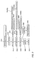
Anhand des Verlaufsschemas nach Figur 2 wird das erfindungsgemäße Verfahren dargestellt. Zuerst liegt eine Wärmestromanforderung S10 vor, die sich beispielsweise aus der Differenz der Katalysatortemperatur TKAT und der Zieltemperatur des Hauptkatalysators 24 ergibt. Dementsprechend erfolgt die Vorgabe eines Grundsplittfaktors S12, der begrenzenden Faktoren S14, S16, und S18 unterliegt. Der erste begrenzende Faktor S14 ist über ein Kennfeld K10 definiert, dem die Katalysatortemperatur TKAT sowie der Katalysatortemperaturgradient TKATG zugrunde liegen. Dementsprechend wird mit steigender Katalysatortemperatur TKAT der Energieeintrag begrenzt, wobei die Differenz der Katalysatortemperatur TKAT zur Zieltemperatur nicht zu berücksichtigen ist. Für ein zweites Kennfeld K12 des zweiten begrenzenden Faktors S16 wird ebenfalls die Katalysatortemperatur TKAT verwendet und zudem die Katalysatortemperaturgradientenänderung TKATGAE. Dadurch wird ein inhomogener Temperaturverlauf im Hauptkatalysator 24 berücksichtigt. Der Splitfaktor wird bei hohen positiven Temperaturgradienten im Hauptkatalysator 24, insbesondere wenn bereits hohe Temperaturen TKAT im Hauptkatalysator 24 vorliegen, begrenzt. Die Rücknahme des Splitfaktors fällt dabei umso stärker aus, wenn zusätzlich der positive Temperaturgradient TKATG eine progressive Zunahme aufweist, um das Risiko eines "Durchgehens" des Hauptkatalysators 24 sicher zu vermeiden. Durch den dritten begrenzenden Faktor S18 wird unter Verwendung eines dritten Kennfeldes K16 der Splitfaktor in Abhängigkeit des Abgasmassenstroms AMS sowie des Abgasmassenstromgradienten AMSG begrenzt, da mit verringertem Abgasmassenstrom auch dessen Kühleffekt abnimmt und da in Betriebssituationen, die einen hohen negativen Abgasmassenstromgradienten bedingen, der HC- und O2-Gehalt im Abgas und damit der chemische Energieeintrag kurzzeitig stark zunimmt. Daraus folgt eine Vorgabe des Lambda-Solls S20 für den Abgaspfad 16 mit dem fetten Abgas und eine Vorgabe des Lambda-Solls S22 für den Abgaspfad 16' mit dem mageren Abgas, wobei das Lambda-Soll für den Abgaspfad 16 mit dem fetten Abgas in einem Schritt S24 vorgesteuert und das Lambda-Soll für den Abgaspfad 16' mit dem mageren Abgas in einem Schritt S26 über den nach dem Hauptkatalysator 24 gemessenen Lambdawert geregelt wird.Based on the flow chart of Figure 2, the inventive method is shown. First, there is a heat flow demand S10 resulting, for example, from the difference of the catalyst temperature TKAT and the target temperature of the
- 1010
- MehrzylindermotorMulti-cylinder engine
- 1212
- Abgasreinigungsanlageemission control system
- 14, 14'14, 14 '
- Zylindercylinder
- 16, 16'16, 16 '
- Abgasstrangexhaust gas line
- 18, 18'18, 18 '
- Vorkatalysatorprecatalyzer
- 20, 20'20, 20 '
- Lambdasondelambda probe
- 2222
- Abgasstrangexhaust gas line
- 2424
- Hauptkatalysatormain catalyst
- 2626
- LambdamessvorrichtungLambda measuring device
- 2828
- Temperaturfühlertemperature sensor
- S10S10
- WärmestromanforderungHeat flow requirement
- S12S12
- Vorgabe eines GrundsplittfaktorsSpecification of a basic split factor
- S14S14
- erster begrenzender Faktorfirst limiting factor
- S16S16
- zweiter begrenzender Faktorsecond limiting factor
- S18S18
- dritter begrenzender Faktorthird limiting factor
- S20S20
- Vorgabe des Lambda-Solls für den fetten AbgaspfadPresetting the lambda setpoint for the rich exhaust path
- S22S22
- Vorgabe des Lambda-Solls für den mageren AbgaspfadPresetting the lambda target for the lean exhaust path
- S24S24
- Vorsteuerungfeedforward
- S26S26
- Regelungregulation
- K10K10
- erstes Kennfeldfirst map
- K12K12
- zweites Kennfeldsecond map
- K14K14
- drittes Kennfeldthird map
- TKATTKAT
- Katalysatortemperaturcatalyst temperature
- TKATGTKATG
- KatalysatortemperaturgradientKatalysatortemperaturgradient
- TKATGAETKATGAE
- KatalysatortemperaturgradientenänderungKatalysatortemperaturgradientenänderung
- AMSAMS
- AbgasmassenstromExhaust gas mass flow
- AMSGAMSG
- AbgasmassenstromgradientAbgasmassenstromgradient
Claims (21)
- Method for controlling the temperature of at least one catalytic converter arranged in an exhaust gas purification system (12) of a multicylinder engine (10) which is capable of running in lean-burn mode, in which energy is introduced into the exhaust gas purification system (12) by means of a lambda split, and the introduction of energy is limited as a function of(a) at least one of the parameters catalytic converter temperature, exhaust gas temperature and exhaust gas mass flow, and/or(b) at least one of the parameters change in the catalytic converter temperature, change in the exhaust gas temperature and change in the exhaust gas mass flow,
characterized in that
the introduction of energy is additionally limited as a function of(c) at least one of the parameters rate of change of the catalytic converter temperature, rate of change of the exhaust gas temperature and rate of change of the exhaust gas mass flow. - Method according to Claim 1, characterized in that the exhaust gas purification system (12) has at least two exhaust gas paths (16, 16'), which can each be supplied with a predeterminable lambda, between the multicylinder engine (10) and the at least one catalytic converter.
- Method according to Claim 1 or 2, characterized in that the exhaust gas purification system (12) has at least one main catalytic converter (24) with at least two primary catalytic converters (18, 18') arranged upstream of it, each primary catalytic converter (18, 18') being arranged in an exhaust gas path (16, 16') which can in each case be supplied with a predeterminable lambda.
- Method according to one of Claims 1 to 3, characterized in that the introduction of energy is limited with a rising, measured or modelled temperature of the at least one catalytic converter, in particular of the main catalytic converter (24).
- Method according to one of Claims 1 to 4, characterized in that the introduction of energy is limited in the event of a high positive time-based temperature gradient in the at least one catalytic converter, in particular in the main catalytic converter (24).
- Method according to one of Claims 1 to 5, characterized in that the introduction of energy is limited in the event of a progressive increase in a positive time-based temperature gradient in the at least one catalytic converter, in particular in the main catalytic converter (24).
- Method according to one of Claims 1 to 6, characterized in that the introduction of energy is limited in the event of a decreasing exhaust gas mass flow.
- Method according to one of Claims 1 to 7, characterized in that the level of energy introduced is determined by a split factor which is established as a function of a request for the introduction of energy, giving the lambda values for the individual exhaust gas paths (16, 16') in the exhaust gas purification system (12).
- Method according to Claim 8, characterized in that in the case of control to a lambda setpoint value upstream of the at least one catalytic converter, in particular the main catalytic converter (24), the lambda in the lean exhaust gas path (16') is closed-loop controlled to the lean lambda value which results from the required split factor as a function of the measured lambda upstream or downstream of the at least one catalytic converter, in particular the main catalytic converter (24), while the rich exhaust gas path (16) is under pilot control.
- Method according to Claim 8 or 9, characterized in that in the event of a very lean setting on the lean exhaust gas path (16'), either at least temporary enriching of the overall mix is permitted, if the pilot control of the rich exhaust gas path (16) is not adapted accordingly, or the pilot control of the rich exhaust gas path (16) is influenced towards lean lambda values, with if appropriate the split factor being lowered or the introduction of energy being reduced.
- Method according to Claim 8 or 9, characterized in that in the event of a lambda > 1.3 on the lean exhaust gas path (16'), either an at least temporary enriching of the overall mix is permitted, if the pilot control of the rich exhaust gas path (16) is not adapted accordingly, or the pilot control of the rich exhaust gas path (16) is influenced towards lean lambda values, with if appropriate the split factor being lowered or the introduction of energy being reduced.
- Method according to Claim 8 or 9, characterized in that in the event of a lambda > 1.45 on the lean exhaust gas path (16'), either an at least temporary enriching of the overall mix is permitted, if the pilot control of the rich exhaust gas path (16) is not adapted accordingly, or the pilot control of the rich exhaust gas path (16) is influenced towards lean lambda values, with if appropriate the split factor being lowered or the introduction of energy being reduced.
- Method according to one of Claims 1 to 12, characterized in that the at least one catalytic converter, in particular the main catalytic converter (24), is an NOx storage catalytic converter, the temperature of which is controlled by introduction of energy into the exhaust gas purification system in such a manner that the NOx storage catalytic converter is desulphurized.
- Method according to one of Claims 1 to 13, characterized in that the introduction of energy is limited as a function of the catalytic converter temperature, the time-based change in the catalytic converter temperature, the rate of change of the catalytic converter temperature and the exhaust gas mass flow.
- Multicylinder engine (10) which is capable of running in lean-burn mode and has an exhaust gas purification system (12) which is capable of lambda splitting and in which there is arranged at least one catalytic converter, the multicylinder engine (10) having means for controlling the temperature of the at least one catalytic converter, which means, by influencing at least one operating parameter of the multicylinder engine (10), introduce energy into the exhaust gas purification system (12) by means of a lambda split, and the introduction of energy being limited as a function of(a) at least one of the parameters catalytic converter temperature, exhaust gas temperature and exhaust gas mass flow and/or(b) at least one of the parameters change in the catalytic converter temperature, change in the exhaust gas temperature and change in the exhaust gas mass flow, and, in addition,(c) at least one of the parameters rate of change of the catalytic converter temperature, rate of change of the exhaust gas temperature and rate of change of the exhaust gas mass flow.
- Multicylinder engine according to Claim 15, characterized in that the exhaust gas purification system (12) has at least two exhaust gas paths (16, 16'), which can each be supplied with a predeterminable lambda, between the multicylinder engine (10) and the at least one catalytic converter.
- Multicylinder engine according to Claim 15 or 16, characterized in that the exhaust gas purification system (12) has at least one main catalytic converter (24) with at least two primary catalytic converters (18, 18') arranged upstream of it, each primary catalytic converter (18, 18') being arranged in an exhaust gas path (16, 16') which can in each case be supplied with a predeterminable lambda.
- Multicylinder engine according to one of Claims 15 to 17, characterized in that the at least one catalytic converter or the main catalytic converter (24) is an NOx storage catalytic converter.
- Multicylinder engine according to Claim 17 or 18, characterized in that the precious metal content of the at least two primary catalytic converters (18, 18') is ≤ 3.59 g/dm3, in particular ≤ 2.87 g/dm3.
- Multicylinder engine according to one of Claims 15 to 19, characterized in that the means comprise a control unit in which models and algorithms for the coordinated control of measures relevant to exhaust gas and power are stored in digitized form.
- Multicylinder engine according to one of Claims 15 to 20, characterized in that the multicylinder engine (10) is a spark-ignition engine, in particular a direct-injection spark ignition engine, or a diesel engine.
Applications Claiming Priority (3)
| Application Number | Priority Date | Filing Date | Title |
|---|---|---|---|
| DE10261911A DE10261911A1 (en) | 2002-12-30 | 2002-12-30 | Process for controlling the temperature of a catalytic converter and multi-cylinder engine with lambda-split exhaust gas cleaning system |
| DE10261911 | 2002-12-30 | ||
| PCT/EP2003/014156 WO2004059150A1 (en) | 2002-12-30 | 2003-12-12 | Method for controlling the temperature of a catalyst and multicylinder engine comprising a lambda splitting exhaust gas cleaning system |
Publications (2)
| Publication Number | Publication Date |
|---|---|
| EP1581733A1 EP1581733A1 (en) | 2005-10-05 |
| EP1581733B1 true EP1581733B1 (en) | 2006-06-07 |
Family
ID=32602452
Family Applications (1)
| Application Number | Title | Priority Date | Filing Date |
|---|---|---|---|
| EP03789253A Expired - Fee Related EP1581733B1 (en) | 2002-12-30 | 2003-12-12 | Method for controlling the temperature of a catalyst and multicylinder engine comprising a lambda splitting exhaust gas cleaning system |
Country Status (6)
| Country | Link |
|---|---|
| US (1) | US7356988B2 (en) |
| EP (1) | EP1581733B1 (en) |
| JP (1) | JP4332120B2 (en) |
| CN (1) | CN100422530C (en) |
| DE (2) | DE10261911A1 (en) |
| WO (1) | WO2004059150A1 (en) |
Families Citing this family (18)
| Publication number | Priority date | Publication date | Assignee | Title |
|---|---|---|---|---|
| DE102004043529B3 (en) * | 2004-09-08 | 2005-09-01 | Siemens Ag | Process for controlling the mixture of a multicylindered Otto engine comprises a cylinder-related lambda control with a cylinder-related controlled stimulation |
| JP4997515B2 (en) * | 2004-12-16 | 2012-08-08 | 独立行政法人産業技術総合研究所 | Chemical detoxification process |
| JP4817294B2 (en) * | 2005-12-02 | 2011-11-16 | 独立行政法人産業技術総合研究所 | Method for selective reduction of nitrogen oxides |
| DE102006007417B4 (en) * | 2006-02-17 | 2012-08-09 | Continental Automotive Gmbh | Method and device for operating an internal combustion engine |
| US7797929B2 (en) | 2007-05-21 | 2010-09-21 | Ford Global Technologies, Llc | Low temperature emission control |
| US7971430B2 (en) * | 2008-04-04 | 2011-07-05 | Ford Global Technologies, Llc | Diesel turbine SCR catalyst |
| US8186146B2 (en) * | 2008-08-27 | 2012-05-29 | Caterpillar Inc. | After-treatment component detection system |
| US8443587B2 (en) * | 2009-02-23 | 2013-05-21 | GM Global Technology Operations LLC | Method for exhaust aftertreatment in an internal combustion engine |
| DE102010027983B4 (en) * | 2010-04-20 | 2022-03-10 | Robert Bosch Gmbh | Method for operating an internal combustion engine for adjusting an exhaust gas probe |
| JP5269174B2 (en) * | 2011-11-28 | 2013-08-21 | 株式会社豊田自動織機 | Exhaust gas purification device in internal combustion engine |
| DE102016202351A1 (en) | 2016-02-16 | 2017-08-17 | Volkswagen Aktiengesellschaft | Method for operating an internal combustion engine and three-cylinder engine for carrying out such a method |
| US10871140B1 (en) | 2019-10-18 | 2020-12-22 | Ford Global Technologies, Llc | Systems and methods for reducing engine torque utilizing split lambda fueling |
| DE102019218427A1 (en) * | 2019-11-28 | 2021-06-02 | Robert Bosch Gmbh | Procedure for diagnosing several lambda probes |
| US11022061B1 (en) | 2020-01-31 | 2021-06-01 | Ford Global Technologies, Llc | Systems and methods for an exhaust gas temperature sensor diagnostics using split lambda engine operation |
| US11174805B2 (en) * | 2020-04-03 | 2021-11-16 | Ford Global Technologies, Llc | Split lambda fueling operation systems and methods |
| US11300063B2 (en) | 2020-07-20 | 2022-04-12 | Ford Global Technologies, Llc | Systems and methods for split lambda catalyst heating |
| EA202092385A1 (en) * | 2020-07-24 | 2022-01-31 | Пауэрхаус Энджин Солюшнз Свитселанд АйПи Холдинг ГмбХ | INTERNAL COMBUSTION ENGINE SYSTEM |
| DE102021111331A1 (en) | 2021-05-03 | 2022-11-03 | Volkswagen Aktiengesellschaft | Desulfurization of a three-way catalytic converter of an internal combustion engine |
Family Cites Families (29)
| Publication number | Priority date | Publication date | Assignee | Title |
|---|---|---|---|---|
| US4012906A (en) * | 1972-06-26 | 1977-03-22 | Nippon Soken, Inc. | Overheat preventing system for exhaust gas purifier of vehicles |
| JPS59150921A (en) * | 1983-02-16 | 1984-08-29 | Toyota Motor Corp | Trap regenerating device in exhaust gas purifying device for diesel engine |
| DE4310145A1 (en) * | 1993-03-29 | 1994-04-07 | Daimler Benz Ag | Multi-cylinder IC engine with at least two groups of cylinders - has individual air-fuel mixture supply, and exhaust gas pipelines assigned to the cylinder groups and opening out into common exhaust gas pipe. |
| US6237330B1 (en) * | 1998-04-15 | 2001-05-29 | Nissan Motor Co., Ltd. | Exhaust purification device for internal combustion engine |
| US6651422B1 (en) * | 1998-08-24 | 2003-11-25 | Legare Joseph E. | Catalyst efficiency detection and heating method using cyclic fuel control |
| DE19852294A1 (en) | 1998-11-12 | 2000-05-18 | Bayerische Motoren Werke Ag | Exhaust system of a multi-cylinder internal combustion engine |
| EP1180063A2 (en) * | 1999-04-19 | 2002-02-20 | Engelhard Corporation | Catylyst composition comprising ceria and a platinum group metal |
| US6244043B1 (en) * | 1999-05-19 | 2001-06-12 | Ford Global Technologies, Inc. | Emission control device air/fuel ratio control system |
| US6354079B1 (en) * | 1999-11-26 | 2002-03-12 | Hyundai Motor Company | Apparatus and method of purifying NOx in the exhaust gas of the diesel engine |
| DE10005954A1 (en) * | 2000-02-09 | 2001-08-16 | Bosch Gmbh Robert | Desulfurization of a storage catalytic converter by heating |
| CN1170058C (en) * | 2000-02-24 | 2004-10-06 | 日产自动车株式会社 | Engine exhaust purifying device |
| DE10031874A1 (en) | 2000-06-30 | 2002-01-17 | Bosch Gmbh Robert | Ignition device has controller that sets up closing time of switch based on current operation mode of internal combustion engine and on second operating parameter |
| DE10034143A1 (en) | 2000-07-13 | 2002-02-07 | Volkswagen Ag | Method for adapting a catalytic converter temperature target range for a NOx storage catalytic converter |
| JP4492776B2 (en) | 2000-09-05 | 2010-06-30 | 株式会社デンソー | Exhaust gas purification device for internal combustion engine |
| JP2002148802A (en) | 2000-11-07 | 2002-05-22 | Tokyo Ohka Kogyo Co Ltd | Photosensitive composition for sandblast and photographic sensitive film using the same |
| DE10055665A1 (en) * | 2000-11-10 | 2002-10-31 | Volkswagen Ag | Method and device for catalyst heating |
| DE10057938A1 (en) | 2000-11-22 | 2002-05-23 | Volkswagen Ag | Regenerating nitrogen oxides storage catalyst in I.C. engine involves extrapolating oxygen-dependent signal from oxygen-sensitive measuring device |
| DE10112938A1 (en) | 2001-03-12 | 2002-10-02 | Volkswagen Ag | Method for controlling a catalyst system warm-up |
| JP3812353B2 (en) | 2001-03-19 | 2006-08-23 | 株式会社日立製作所 | Semiconductor power converter |
| JP3838339B2 (en) * | 2001-03-27 | 2006-10-25 | 三菱ふそうトラック・バス株式会社 | Exhaust gas purification device for internal combustion engine |
| DE10123148B4 (en) | 2001-05-03 | 2011-09-15 | Volkswagen Ag | Method and device for desulfurization of a precatalyst |
| JP3879833B2 (en) * | 2002-03-04 | 2007-02-14 | 三菱自動車工業株式会社 | Exhaust gas purification device for internal combustion engine |
| DE10228659A1 (en) * | 2002-06-27 | 2004-01-22 | Daimlerchrysler Ag | Method for monitoring an exhaust system of a motor vehicle |
| JP3969273B2 (en) * | 2002-10-03 | 2007-09-05 | 株式会社デンソー | Exhaust gas purification device for internal combustion engine |
| JP4140371B2 (en) * | 2002-12-16 | 2008-08-27 | 日産自動車株式会社 | Particulate filter regeneration device and engine exhaust gas purification device |
| JP4464613B2 (en) * | 2003-02-28 | 2010-05-19 | 三菱自動車工業株式会社 | Catalyst temperature estimation apparatus and catalyst temperature estimation method |
| JP2005048678A (en) * | 2003-07-30 | 2005-02-24 | Nissan Motor Co Ltd | Combustion control device for internal combustion engine |
| DE602004010991T2 (en) * | 2003-11-12 | 2008-12-24 | Toyota Jidosha Kabushiki Kaisha, Toyota-shi | Device and method for controlling the fuel injection for an internal combustion engine |
| DE102004031321C5 (en) * | 2004-06-29 | 2020-06-25 | Robert Bosch Gmbh | Method for metering a fuel into an exhaust gas duct of an internal combustion engine and device for carrying out the method |
-
2002
- 2002-12-30 DE DE10261911A patent/DE10261911A1/en not_active Withdrawn
-
2003
- 2003-12-12 WO PCT/EP2003/014156 patent/WO2004059150A1/en active IP Right Grant
- 2003-12-12 CN CNB2003801075630A patent/CN100422530C/en not_active Expired - Fee Related
- 2003-12-12 DE DE50303755T patent/DE50303755D1/en not_active Expired - Lifetime
- 2003-12-12 EP EP03789253A patent/EP1581733B1/en not_active Expired - Fee Related
- 2003-12-12 JP JP2004562741A patent/JP4332120B2/en not_active Expired - Fee Related
- 2003-12-12 US US10/541,004 patent/US7356988B2/en not_active Expired - Fee Related
Also Published As
| Publication number | Publication date |
|---|---|
| CN1732337A (en) | 2006-02-08 |
| DE10261911A1 (en) | 2004-07-29 |
| JP2006521482A (en) | 2006-09-21 |
| DE50303755D1 (en) | 2006-07-20 |
| US7356988B2 (en) | 2008-04-15 |
| US20060080951A1 (en) | 2006-04-20 |
| JP4332120B2 (en) | 2009-09-16 |
| WO2004059150A1 (en) | 2004-07-15 |
| CN100422530C (en) | 2008-10-01 |
| EP1581733A1 (en) | 2005-10-05 |
Similar Documents
| Publication | Publication Date | Title |
|---|---|---|
| EP1581733B1 (en) | Method for controlling the temperature of a catalyst and multicylinder engine comprising a lambda splitting exhaust gas cleaning system | |
| DE102011007364A1 (en) | Method and apparatus for regeneration of a particulate filter in a Y exhaust system | |
| EP3572634B1 (en) | Method and device for treating the waste gas produced by a combustion engine | |
| EP1205648B1 (en) | Method and arrangement for a catalyst heating system | |
| EP1132584B1 (en) | Method and apparatus for control of heating an exhaust gas purification system of internal combustion engines | |
| EP1180201A1 (en) | Method for desulphurating a nox-storage catalyst that is arranged in an exhaust channel of a combustion engine | |
| DE10226873B4 (en) | Method for controlling the mode selection of an internal combustion engine | |
| DE10016219A1 (en) | Control of hot regeneration stage in engine exhaust purification system, determines temperatures, flow rate and composition, to control total energy input | |
| DE102016210897B4 (en) | Control of nitrogen oxide emissions in high-load operating phases | |
| EP1143131A2 (en) | Multiple exhaust gas system and method to regulate an air/fuel ratio and to control the regeneration of an NOx storage catalyst | |
| DE10154041B4 (en) | Method and device for reducing pollutant emissions | |
| WO2000070203A1 (en) | Desulphurisation method | |
| EP1235977B1 (en) | Method and device for controlling a heating phase of at least one catalytic converter in an exhaust channel of an internal combustion engine | |
| DE10130053B4 (en) | Method and device for desulphurisation of a NOX storage catalytic converter | |
| DE102005063204B4 (en) | Design and operation of a lean-running internal combustion engine with adapted exhaust aftertreatment | |
| EP1391592B1 (en) | Method for operating a lean burn internal combustion engine having an exhaust gas purification system | |
| EP1581729B1 (en) | Method for controlling an internal combustion engine and lean operating internal combustion engine | |
| DE10249609B4 (en) | Method for controlling a NOx storage catalytic converter | |
| EP1108875B1 (en) | Method for heating a catalyst of a lean burn internal combustion engine especially at idle | |
| DE10230676B4 (en) | Method for thermal regeneration of an exhaust gas purification device and internal combustion engine system | |
| EP1479894B1 (en) | Method for operating an internal combustion engine | |
| EP1387070B1 (en) | Procedure and device for the operating of an exhaust purification intallation for an internal combustion engine | |
| EP1391601A2 (en) | Method to operate an internal combustion engine with direct injection | |
| EP1491749B1 (en) | Method for operating an internal combustion engine | |
| DE102021203678A1 (en) | Method and computing unit for operating an exhaust gas burner |
Legal Events
| Date | Code | Title | Description |
|---|---|---|---|
| PUAI | Public reference made under article 153(3) epc to a published international application that has entered the european phase |
Free format text: ORIGINAL CODE: 0009012 |
|
| 17P | Request for examination filed |
Effective date: 20050801 |
|
| AK | Designated contracting states |
Kind code of ref document: A1 Designated state(s): AT BE BG CH CY CZ DE DK EE ES FI FR GB GR HU IE IT LI LU MC NL PT RO SE SI SK TR |
|
| GRAP | Despatch of communication of intention to grant a patent |
Free format text: ORIGINAL CODE: EPIDOSNIGR1 |
|
| RBV | Designated contracting states (corrected) |
Designated state(s): DE ES FR GB |
|
| RIN1 | Information on inventor provided before grant (corrected) |
Inventor name: PHILIPP, KAI Inventor name: POTT, EKKEHARD Inventor name: BREE, ERIC |
|
| GRAS | Grant fee paid |
Free format text: ORIGINAL CODE: EPIDOSNIGR3 |
|
| GRAA | (expected) grant |
Free format text: ORIGINAL CODE: 0009210 |
|
| AK | Designated contracting states |
Kind code of ref document: B1 Designated state(s): DE ES FR GB |
|
| REG | Reference to a national code |
Ref country code: GB Ref legal event code: FG4D Free format text: NOT ENGLISH |
|
| REF | Corresponds to: |
Ref document number: 50303755 Country of ref document: DE Date of ref document: 20060720 Kind code of ref document: P |
|
| PG25 | Lapsed in a contracting state [announced via postgrant information from national office to epo] |
Ref country code: ES Free format text: LAPSE BECAUSE OF FAILURE TO SUBMIT A TRANSLATION OF THE DESCRIPTION OR TO PAY THE FEE WITHIN THE PRESCRIBED TIME-LIMIT Effective date: 20060918 |
|
| GBT | Gb: translation of ep patent filed (gb section 77(6)(a)/1977) |
Effective date: 20060923 |
|
| PLBE | No opposition filed within time limit |
Free format text: ORIGINAL CODE: 0009261 |
|
| STAA | Information on the status of an ep patent application or granted ep patent |
Free format text: STATUS: NO OPPOSITION FILED WITHIN TIME LIMIT |
|
| EN | Fr: translation not filed | ||
| 26N | No opposition filed |
Effective date: 20070308 |
|
| PG25 | Lapsed in a contracting state [announced via postgrant information from national office to epo] |
Ref country code: FR Free format text: LAPSE BECAUSE OF FAILURE TO SUBMIT A TRANSLATION OF THE DESCRIPTION OR TO PAY THE FEE WITHIN THE PRESCRIBED TIME-LIMIT Effective date: 20070309 |
|
| PG25 | Lapsed in a contracting state [announced via postgrant information from national office to epo] |
Ref country code: FR Free format text: LAPSE BECAUSE OF FAILURE TO SUBMIT A TRANSLATION OF THE DESCRIPTION OR TO PAY THE FEE WITHIN THE PRESCRIBED TIME-LIMIT Effective date: 20060607 |
|
| PGFP | Annual fee paid to national office [announced via postgrant information from national office to epo] |
Ref country code: DE Payment date: 20171231 Year of fee payment: 15 |
|
| PGFP | Annual fee paid to national office [announced via postgrant information from national office to epo] |
Ref country code: GB Payment date: 20181221 Year of fee payment: 16 |
|
| REG | Reference to a national code |
Ref country code: DE Ref legal event code: R119 Ref document number: 50303755 Country of ref document: DE |
|
| PG25 | Lapsed in a contracting state [announced via postgrant information from national office to epo] |
Ref country code: DE Free format text: LAPSE BECAUSE OF NON-PAYMENT OF DUE FEES Effective date: 20190702 |
|
| GBPC | Gb: european patent ceased through non-payment of renewal fee |
Effective date: 20191212 |
|
| PG25 | Lapsed in a contracting state [announced via postgrant information from national office to epo] |
Ref country code: GB Free format text: LAPSE BECAUSE OF NON-PAYMENT OF DUE FEES Effective date: 20191212 |