EP1580389B1 - Joint d'angle pour un assemblage à onglet des profiles creux de fenêtres ou de portes - Google Patents
Joint d'angle pour un assemblage à onglet des profiles creux de fenêtres ou de portes Download PDFInfo
- Publication number
- EP1580389B1 EP1580389B1 EP05005694A EP05005694A EP1580389B1 EP 1580389 B1 EP1580389 B1 EP 1580389B1 EP 05005694 A EP05005694 A EP 05005694A EP 05005694 A EP05005694 A EP 05005694A EP 1580389 B1 EP1580389 B1 EP 1580389B1
- Authority
- EP
- European Patent Office
- Prior art keywords
- connecting means
- corner connecting
- corner
- channel
- hollow profiles
- Prior art date
- Legal status (The legal status is an assumption and is not a legal conclusion. Google has not performed a legal analysis and makes no representation as to the accuracy of the status listed.)
- Active
Links
Images


Classifications
-
- E—FIXED CONSTRUCTIONS
- E06—DOORS, WINDOWS, SHUTTERS, OR ROLLER BLINDS IN GENERAL; LADDERS
- E06B—FIXED OR MOVABLE CLOSURES FOR OPENINGS IN BUILDINGS, VEHICLES, FENCES OR LIKE ENCLOSURES IN GENERAL, e.g. DOORS, WINDOWS, BLINDS, GATES
- E06B3/00—Window sashes, door leaves, or like elements for closing wall or like openings; Layout of fixed or moving closures, e.g. windows in wall or like openings; Features of rigidly-mounted outer frames relating to the mounting of wing frames
- E06B3/96—Corner joints or edge joints for windows, doors, or the like frames or wings
- E06B3/964—Corner joints or edge joints for windows, doors, or the like frames or wings using separate connection pieces, e.g. T-connection pieces
- E06B3/968—Corner joints or edge joints for windows, doors, or the like frames or wings using separate connection pieces, e.g. T-connection pieces characterised by the way the connecting pieces are fixed in or on the frame members
- E06B3/9681—Corner joints or edge joints for windows, doors, or the like frames or wings using separate connection pieces, e.g. T-connection pieces characterised by the way the connecting pieces are fixed in or on the frame members by press fit or adhesion
- E06B3/9682—Mitre joints
-
- E—FIXED CONSTRUCTIONS
- E06—DOORS, WINDOWS, SHUTTERS, OR ROLLER BLINDS IN GENERAL; LADDERS
- E06B—FIXED OR MOVABLE CLOSURES FOR OPENINGS IN BUILDINGS, VEHICLES, FENCES OR LIKE ENCLOSURES IN GENERAL, e.g. DOORS, WINDOWS, BLINDS, GATES
- E06B3/00—Window sashes, door leaves, or like elements for closing wall or like openings; Layout of fixed or moving closures, e.g. windows in wall or like openings; Features of rigidly-mounted outer frames relating to the mounting of wing frames
- E06B3/96—Corner joints or edge joints for windows, doors, or the like frames or wings
- E06B3/9616—Corner joints or edge joints for windows, doors, or the like frames or wings characterised by the sealing at the junction of the frame members
- E06B3/962—Mitre joints
Definitions
- the invention relates to a corner connector for mitred hollow sections with the features of the preamble of claim 1.
- One from the FR 2 759 111 known corner connector has a distribution channel, which, however, is not continuous across the longitudinal center plane. A production in the extrusion process is therefore not possible, but the distribution channel must be incorporated later.
- a corner joint for mitred hollow sections known which engages with its legs in the profile ends of the hollow sections and has a running in the direction of the miter joint distribution channel for a sealant, wherein an opening for the sealant is provided in the region of the miter and wherein the distribution channel transverse to Longitudinal plane of the corner connector is continuous and both ends of the distribution channel with a transverse bore for input and / or supply of the sealant to the mitres are connected.
- the distribution channel is transverse to the longitudinal center plane of the corner connector.
- the distribution channel is formed, so to speak, as a continuous hollow chamber. This construction allows the corner connector to be manufactured by extrusion, while at the same time providing the continuous connection Distribution channel can be introduced. It is therefore no additional manufacturing step for the arrangement of the distribution channel required. Accordingly, the production of the connector designed as rational and manufacturing technology extremely advantageous, which in comparison to the prior art, a lesser time and effort is required. This also reduces the production costs.
- the continuous distribution channel ensures that the adhesive is routed to the mitres and at the same time possibly guided over at least one transverse bore to the inner and outer legs of the corner connector.
- At least one end of the distribution channel may communicate with a transverse bore for inputting and / or feeding the adhesive to the mitres.
- a transverse bore in the outer corner region of the corner connector can ensure that the injected adhesive is supplied to the distribution channel.
- a further transverse bore at the inner corner region of the corner connector ensures that the adhesive is forwarded to the rearward mitres and thus leads to an adhesion of at least a portion of the rear sides or inner legs of the corner connector to the adjoining region of the respective hollow profile.
- the aforementioned transverse bores can be introduced in a simple manner after production of the extruded profile.
- an input channel may be provided which is in communication with the distribution channel or the transverse bore which leads into the distribution channel.
- the input channel can be wide be configured so that the processor can select the injection port for the adhesive at different locations in the miter joint.
- the inlet channel may be bounded by the corner connector and the slipped hollow sections so that the adhesive is forced to penetrate into the distribution channel.
- the input channel may be conical or funnel-shaped and taper in the direction of the distribution channel or transverse bore.
- a flowing transition can be provided between the input channel and the distribution channel or the transverse bores so that the adhesive can flow in an ideal manner into the distribution channel. Accordingly, therefore, the input channel is introduced only in a manufacturing step after the production of the extruded profile.
- the input channel and the transverse bores can be introduced simultaneously or directly one behind the other, for. B. drilled.
- the input channel may be formed as a stepped bore or countersink.
- This stepped bore or for lowering the adjoining transverse bore is advantageously arranged centered.
- a transversely extending to the distribution channel return channel may be provided, which extends over the height of the corner connector and is arranged in the inner corner region of the corner connector. This return channel ensures even distribution of the adhesive to the mitres in the inner corner area.
- the return channel can - as well as the input channel - be limited by the corner connector and the deferred hollow sections, so that the adhesive is forced to continue to flow.
- On the return channel can connect to each side of a side channel, which is limited by the corner connector and the deferred hollow sections.
- the adhesive flows into these side channels, where it bonds the mitres with the corner connector.
- the adhesive can be injected from the injection opening in the area of the miter joint of the hollow channels into the inlet channel, the adjoining side channels, the distribution channel and the return channel and the adjoining side channels. Both in the outer and in the inner corner region of the corner connector thus takes place a bond and thus reliable connection between corner connectors and hollow sections. Multiple injection of adhesive is not required.
- the outer edge of the corner connector (in the outer corner region) may be rounded so that the adhesive can spread evenly on both sides and can not form undesirable accumulations of adhesive on a sharp edge.
- the rounded edge of the corner connector ensures that the foremost corner area between the corner connector and miter joint for the absorption of adhesive is increased.
- the corner connector may be non-positively connected to the hollow profiles.
- the non-positive connection is preliminary, already made prior to the injection of the adhesive, and in this way already ensures a correct positioning of the components to each other. After injection of the adhesive, it is no longer necessary to additionally compress the corner connector with the hollow profiles.
- the corner connector can be connected to the hollow profiles by mechanical fastening means, in particular pinned or screwed. These fasteners can engage in corresponding receptacles of the corner connector, wherein z. B. screws from the outside through the Hohprofile and are screwed into the corner connector. It can, for. B. but also be provided that one or more of the hollow profiles projecting pins engage in corresponding recesses of the corner connector.
- the corner connector may have closed hollow chambers to its free leg ends, which ensure high stability and torsional rigidity of the corner connector.
- the corner connector may be an extruded profile or cut from an extruded profile, so that - as already mentioned - at the same time the continuous distribution channel can be introduced.
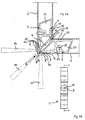
- FIGS. 1 and 2 show two possible embodiments of the invention corner connector 1 for mitred hollow sections 2, 3 of windows, doors or the like.
- the two variants differ only in their mechanical fastening means, which are explained in more detail below.
- FIGS. 3a, 3b, 4a, 4b Such corner joints according to the prior art in a perspective view.
- the corner connectors 101, 102, 103, 104 shown there are not realized in the present invention.
- the corner connectors 101, 102, 103, 104 according to the prior art according to the FIGS. 3a, 3b, 4a, 4b as well as according to the present invention according to the FIGS. 1 and 2 each engage with their legs in the profile ends of the hollow sections 2, 3 a.
- the corner connector 1 is an extruded profile or cut from an extruded profile, wherein the distribution channel 7 transverse to the longitudinal center plane E-E of the corner connector 1 is continuous.
- the distribution channel 7 is connected at its two ends with a respective transverse bore 9, 10 in order to be able to introduce the adhesive into the distribution channel 7 and also from the distribution channel 7 to the mitres 11 in the inner corner region 12 zuzu unor.
- an input channel 15 is provided, which is in communication with the transverse bore 9.
- the inlet channel 15 is so wide outwardly that different positions for the injection opening 8, 8 ', 8 "are selected for the adhesive at various locations in the miter 6. This possibility of different positioning of the injection openings 8, 8' , 8 "is also through the various possible positions of the adhesive nozzle 14, 14 ', 14 ", which are once shown by a solid line and two dashed lines illustrates.
- the inlet channel 15 is bounded by the corner connector 1 and the pushed-hollow sections 2, 3, so that the injected adhesive is forced to flow further into the distribution channel 7 and the side channels 16, 17.
- the input channel 15 is conical or funnel-shaped and tapers in the direction of the distribution channel 7.
- the input channel 15 is thus not continuous as the distribution channel 7 is formed and must therefore be introduced later as the transverse holes 9, 10 to the extruded corner connector 1.
- the input channel 15 is designed as a stepped bore or countersink.
- a side channel 16, 17, which is limited in each case by the corner connector 1 and the deferred hollow sections 2, 3.
- the injected into the side channels 16, 17 adhesive connects the corner connector 1 in the outer corner area with the mitres 11 of the hollow sections 2, 3rd
- FIG. 2a are the hollow sections 2, 3 pinned to the corner connector 1, wherein a pin 24 or a rivet from the outside via the respective hollow profile 2, 3 engages in a corresponding recess 25 of the corner connector 1.
- the corner connector 1 is made of aluminum or an aluminum alloy and thus of a suitable material for an extrusion process.
Landscapes
- Engineering & Computer Science (AREA)
- Civil Engineering (AREA)
- Structural Engineering (AREA)
- Joining Of Corner Units Of Frames Or Wings (AREA)
- Connector Housings Or Holding Contact Members (AREA)
- Standing Axle, Rod, Or Tube Structures Coupled By Welding, Adhesion, Or Deposition (AREA)
- Non-Disconnectible Joints And Screw-Threaded Joints (AREA)
- Cleaning In General (AREA)
Claims (18)
- Joint d'angle (1) pour des profilés creux (2, 3), coupés en onglet, de fenêtres, portes ou analogue, s'engageant, par ses branches (4, 5) dans les extrémités de profilés des profilés creux (2, 3) et présentant au moins un canal de distribution (7), s'étendant sensiblement en direction du joint d'onglet (6), pour un adhésif injectable, une ouverture d'injection pour l'adhésif étant prévue dans la zone du joint en onglet (6), le canal de distribution (7) étant continu, transversalement au plan médian longitudinal (E-E) du joint d'angle (1),
caractérisé en ce que
l'adhésif est amené au canal de distribution (7) par l'ouverture d'injection (8) et un perçage transversal (9) ménagé dans la zone d'angle extérieure (13) du joint d'angle (1) et retransmis, du canal de distribution (7) aux onglets (11) arrière, par un autre perçage transversal (10) ménagé sur la zone d'angle intérieure (12) du joint d'angle (1). - Joint d'angle (1) selon la revendication 1, caractérisé en ce que la hauteur du joint d'angle (1) correspond à la hauteur libre des profilés creux (2, 3), pour éviter un ripage ou un coincement du joint d'angle (1) dans les profilés creux (2, 3).
- Joint d'angle (1) selon l'une des revendications précédentes, caractérisé en ce que, dans la zone extérieure (13) du joint d'angle (1), est prévu un canal d'entrée (15), relié au canal de distribution (7) et au perçage transversal (9).
- Joint d'angle (1) selon la revendication 3, caractérisé en ce que le canal d'entrée (15) est délimité par le joint d'angle (1) et les profilés creux (2, 3) enfilés.
- Joint d'angle (1) selon l'une des revendications 3 ou 4, caractérisé en ce que le canal d'entrée (15) est conique ou en forme d'entonnoir et va en s'effilant en évoluant en direction du canal de distribution (7).
- Joint d'angle (1) selon l'une des revendications 3 à 5, caractérisé en ce que le canal d'entrée (15) est configuré sous forme de perçage étagé ou de saignée ou chanfrein.
- Joint d'angle (1) selon l'une des revendications 3 à 6, caractérisé en ce qu'un canal latéral (16, 17), délimité par le joint d'angle (1) et les profilés creux (2, 3) enfilés, se raccorde des deux côtés au canal d'entrée (15).
- Joint d'angle (1) selon l'une des revendications précédentes, caractérisé en ce qu'un canal arrière (18), s'étendant transversalement au canal de distribution (7), est prévu, s'étendant sur la hauteur du joint d'angle (1) et disposé dans la zone d'angle intérieure (12) du joint d'angle (1).
- Joint d'angle (1) selon la revendication 8, caractérisé en ce que le canal arrière (18) est délimité par le joint d'angle (1) et les profilés creux (2, 3) enfilés.
- Joint d'angle (1) selon l'une des revendications 8 et 9, caractérisé en ce qu'un canal latéral (19, 20), délimité par le joint d'angle (1) et les profilés creux (2, 3) enfilés, se raccorde des deux côtés au canal arrière (18).
- Joint d'angle (1) selon la revendication 10, caractérisé en ce que l'adhésif est susceptible d'être introduit dans le canal d'entrée (15), les canaux latéraux (16, 17) s'y raccordant, le canal de distribution (7), ainsi que le canal arrière (18) et les canaux latéraux (19, 20) s'y raccordant.
- Joint d'angle (1) selon l'une des revendications précédentes, caractérisé en ce que l'arête extérieure (21) du joint d'angle (1) est arrondie.
- Joint d'angle (1) selon l'une des revendications précédentes, caractérisé en ce que le joint d'angle (1) est relié aux profilés creux (2, 3) par une liaison à interaction de forces.
- Joint d'angle (1) selon la revendication 13, caractérisé en ce que le joint d'angle (1) est relié aux profilés creux (2, 3) par des moyens de fixation mécaniques, en particulier par pressage, goupillage ou vissage.
- Joint d'angle (1) selon la revendication 14, caractérisé en ce que le joint d'angle (1) est fixé aux profilés creux (2, 3), avec appui, opérant par interaction de forces, dans le joint en onglet (6), à l'aide des moyens de fixation.
- Joint d'angle (1) selon l'une des revendications précédentes, caractérisé en ce que le joint d'angle (1) présente des chambres creuses (26, 27), fermées vers ses extrémités de branches libres.
- Joint d'angle (1) selon l'une des revendications précédentes, caractérisé en ce que le joint d'angle (1) est un profilé d'extrusion, ou coupé à partir d'un profilé d'extrusion.
- Joint d'angle (1) selon l'une des revendications précédentes, caractérisé en ce que le joint d'angle (1) est composé d'aluminium ou d'un alliage d'aluminium.
Applications Claiming Priority (2)
| Application Number | Priority Date | Filing Date | Title |
|---|---|---|---|
| DE102004014595A DE102004014595B3 (de) | 2004-03-23 | 2004-03-23 | Eckverbinder |
| DE102004014595 | 2004-03-23 |
Publications (3)
| Publication Number | Publication Date |
|---|---|
| EP1580389A2 EP1580389A2 (fr) | 2005-09-28 |
| EP1580389A3 EP1580389A3 (fr) | 2007-02-21 |
| EP1580389B1 true EP1580389B1 (fr) | 2009-03-11 |
Family
ID=34854042
Family Applications (1)
| Application Number | Title | Priority Date | Filing Date |
|---|---|---|---|
| EP05005694A Active EP1580389B1 (fr) | 2004-03-23 | 2005-03-16 | Joint d'angle pour un assemblage à onglet des profiles creux de fenêtres ou de portes |
Country Status (3)
| Country | Link |
|---|---|
| EP (1) | EP1580389B1 (fr) |
| AT (1) | ATE425340T1 (fr) |
| DE (2) | DE102004014595B3 (fr) |
Families Citing this family (17)
| Publication number | Priority date | Publication date | Assignee | Title |
|---|---|---|---|---|
| GB0415659D0 (en) * | 2004-07-13 | 2004-08-18 | Rehau Ltd | Window frames |
| DE102006050572B4 (de) * | 2006-07-08 | 2017-11-23 | Hueck Gmbh & Co. Kg | Profilrahmen |
| DE102006047542B4 (de) * | 2006-10-07 | 2008-07-24 | Hydro Building Systems Gmbh | Rahmen für Fenster, Türen, Fassadenelemente und dergleichen |
| DE102011107060A1 (de) * | 2011-07-11 | 2013-01-17 | Hörmann Kg Brandis | Verfahren zum Verbinden von Hohlprofilstäben, Eckverbinder sowie Tür-/Tüblatt-/Verglasungsrahmen |
| DE102011118211A1 (de) * | 2011-11-11 | 2013-05-16 | Heroal - Johann Henkenjohann Gmbh & Co. Kg | Eckverbindung eines Rahmens mit einem mit einem Klebstoff ausgefüllten Innenraum |
| DE102013100253A1 (de) * | 2013-01-11 | 2014-07-31 | Eduard Hueck Gmbh & Co Kg | Eckverbinder |
| DE202013103624U1 (de) | 2013-08-12 | 2014-11-14 | Raico Bautechnik Gmbh | Eckverbinder zur Verbindung auf Gehrung geschnittener Hohlprofile |
| DE102014112092A1 (de) * | 2014-08-25 | 2016-02-25 | SCHÜCO International KG | Tür, Fenster oder Fassadenelement mit einem Eckverbinder |
| DE102017104463B3 (de) | 2017-03-03 | 2018-08-23 | Nieke Composites Gmbh | Leichtbaukonstruktion und Verfahren |
| CN107023248B (zh) * | 2017-06-17 | 2019-04-05 | 广州市福里事复合材料有限公司 | 一种门窗型材的组角方法 |
| ES2759331B2 (es) * | 2018-11-07 | 2021-04-08 | Cano Manuel Blazquez | Escuadra de tetones |
| AU2020204556A1 (en) * | 2019-07-12 | 2021-01-28 | Jeld-Wen, Inc. | Systems and methods for joining fenestration frame member |
| USD1009306S1 (en) | 2021-05-18 | 2023-12-26 | Jeld-Wen, Inc. | Corner key |
| USD1009307S1 (en) | 2021-05-18 | 2023-12-26 | Jeld-Wen, Inc. | Corner key |
| USD1009305S1 (en) | 2021-05-18 | 2023-12-26 | Jeld-Wen, Inc. | Corner key |
| USD1009308S1 (en) | 2021-05-18 | 2023-12-26 | Jeld-Wen, Inc. | Corner key |
| DE102022126595A1 (de) * | 2022-10-12 | 2024-04-18 | REHAU Industries SE & Co. KG | Verfahren zur Erzeugung einer Eckverbindung, Verbindungselement für eine Eckverbindung sowie Eckverbindung |
Citations (1)
| Publication number | Priority date | Publication date | Assignee | Title |
|---|---|---|---|---|
| DE3015140A1 (de) * | 1980-04-19 | 1981-10-29 | Gebrüder Uhl GmbH & Co KG, 7981 Vogt | Stabilisierungs- undausrichtelement fuer aus profilteilen zusammengesetzte rahmen von fenstern, tueren o.dgl. |
Family Cites Families (7)
| Publication number | Priority date | Publication date | Assignee | Title |
|---|---|---|---|---|
| DE9321056U1 (de) * | 1993-02-10 | 1995-11-16 | Schueco Int Kg | Eckverbindung auf Gehrung geschnittener Hohlprofile eines Rahmens für Fenster, Türen oder Fassaden |
| DE4305377C2 (de) * | 1993-02-22 | 2000-06-15 | Hueck Eduard Gmbh Co Kg | Gehrungseckverbindung |
| DE19633783C1 (de) * | 1996-08-22 | 1998-06-04 | Hueck Eduard Gmbh Co Kg | Gehrungseckverbindung |
| FR2759111B1 (fr) * | 1997-02-06 | 1999-10-22 | Alcan France | Dispositif pour l'assemblage de profiles d'un chassis de porte, fenetre ou analogue |
| US5921037A (en) * | 1997-03-25 | 1999-07-13 | Pella Corporation | Fenestration product with unitary frame members and method of manufacture |
| DE10118791B4 (de) * | 2001-04-18 | 2012-06-21 | Adrian Kosak | Verbindungselement |
| DE20217301U1 (de) * | 2002-11-09 | 2004-03-18 | SCHÜCO International KG | Eckverbinder für auf Gehrung geschnittene Hohlprofile eines Rahmens |
-
2004
- 2004-03-23 DE DE102004014595A patent/DE102004014595B3/de not_active Expired - Fee Related
-
2005
- 2005-03-16 EP EP05005694A patent/EP1580389B1/fr active Active
- 2005-03-16 DE DE502005006778T patent/DE502005006778D1/de active Active
- 2005-03-16 AT AT05005694T patent/ATE425340T1/de active
Patent Citations (1)
| Publication number | Priority date | Publication date | Assignee | Title |
|---|---|---|---|---|
| DE3015140A1 (de) * | 1980-04-19 | 1981-10-29 | Gebrüder Uhl GmbH & Co KG, 7981 Vogt | Stabilisierungs- undausrichtelement fuer aus profilteilen zusammengesetzte rahmen von fenstern, tueren o.dgl. |
Also Published As
| Publication number | Publication date |
|---|---|
| DE502005006778D1 (de) | 2009-04-23 |
| DE102004014595B3 (de) | 2005-12-22 |
| EP1580389A2 (fr) | 2005-09-28 |
| EP1580389A3 (fr) | 2007-02-21 |
| ATE425340T1 (de) | 2009-03-15 |
Similar Documents
| Publication | Publication Date | Title |
|---|---|---|
| EP1580389B1 (fr) | Joint d'angle pour un assemblage à onglet des profiles creux de fenêtres ou de portes | |
| EP2901889B1 (fr) | Meuble | |
| EP0610675B1 (fr) | Joint d'angle à onglet de profilés creux pour cadres de fenêtres, portes ou façades | |
| EP2154323A2 (fr) | Joint d'angle pour un assemblage à onglet de profiles creux | |
| EP3124734B1 (fr) | Systeme de liaison destine a relier un jambage a un profil de cadre d'une fenetre ou d'une porte en matiere plastique | |
| EP3135849B1 (fr) | Liaison bout-a-bout pour injection de colle et combinaison de raccord et cadre | |
| DE3236719C2 (de) | Klemmverbinder für Profilleisten | |
| WO2005019588A1 (fr) | Raccord d'angle et procede de fabrication associe | |
| EP2933507B1 (fr) | Système de joint en bout, encadrement de fenêtre/de porte ou encadrement de vantail de porte/de fenêtre et élément de profilé d'encadrement | |
| DE4442074C2 (de) | Pfosten-, Sprossen- und Kreuzverbinder | |
| EP0716210A2 (fr) | Joint d'angle pour profilé en plastic | |
| EP1849944B1 (fr) | Ferrure de charnière pour la fixation articulée d'un cadre, en particulier d'un cadre de volet | |
| DE19828382C2 (de) | Anordnung zum Befestigen eines einen Hohlquerschnitt aufweisenden Pfostens am Blendrahmen eines Fensters oder einer Türe aus Kunststoff oder Leichtmetall | |
| EP0835978B1 (fr) | Cadre pour fenêtres, portes, façades ou des choses pareilles | |
| DE19900957C2 (de) | Eckverbinder für Hohlprofilrahmen von Fenstern und Türen | |
| DE1901814U (de) | Vorrichtung zum verbinden von rahmenteilen. | |
| EP3916188A1 (fr) | Dispositif de liaison permettant de relier deux composants dans la zone de butée d'une construction de porte ou de fenêtre, ainsi qu'un procédé de réalisation d'une telle liaison à onglets sur deux composants | |
| DE102004014598A1 (de) | Stoßverbinder zur Verbindung von Profilen | |
| DE202005006847U1 (de) | Eckverbindung für Fenster | |
| DE19940574C1 (de) | Anordnung zur Bildung einer Kreuzverbindung zwischen einem Längspfosten und einem Querpfosten bei einem Fenster oder einer Türe aus Kunststoff oder Leichtmetall | |
| EP0291973B1 (fr) | Pièce de jonction de deux barres profilées aboutissant angulairement pour cadres de fenêtre ou porte | |
| WO1999004125A1 (fr) | Partie penture a placer sur des huisseries en bois ou en metal pour fenetres ou portes | |
| EP1666679B1 (fr) | Connection de profilés de fenêtre, porte ou toiture se rencontrant angulairement | |
| AT412412B (de) | Adapterprofil | |
| EP2679759A1 (fr) | Connecteur d'angle pour châssis en corps creux |
Legal Events
| Date | Code | Title | Description |
|---|---|---|---|
| PUAI | Public reference made under article 153(3) epc to a published international application that has entered the european phase |
Free format text: ORIGINAL CODE: 0009012 |
|
| AK | Designated contracting states |
Kind code of ref document: A2 Designated state(s): AT BE BG CH CY CZ DE DK EE ES FI FR GB GR HU IE IS IT LI LT LU MC NL PL PT RO SE SI SK TR |
|
| AX | Request for extension of the european patent |
Extension state: AL BA HR LV MK YU |
|
| RAP1 | Party data changed (applicant data changed or rights of an application transferred) |
Owner name: HERMANN GUTMANN WERKE AG |
|
| PUAL | Search report despatched |
Free format text: ORIGINAL CODE: 0009013 |
|
| AK | Designated contracting states |
Kind code of ref document: A3 Designated state(s): AT BE BG CH CY CZ DE DK EE ES FI FR GB GR HU IE IS IT LI LT LU MC NL PL PT RO SE SI SK TR |
|
| AX | Request for extension of the european patent |
Extension state: AL BA HR LV MK YU |
|
| 17P | Request for examination filed |
Effective date: 20070813 |
|
| AKX | Designation fees paid |
Designated state(s): AT CH DE LI |
|
| 17Q | First examination report despatched |
Effective date: 20080724 |
|
| GRAP | Despatch of communication of intention to grant a patent |
Free format text: ORIGINAL CODE: EPIDOSNIGR1 |
|
| RTI1 | Title (correction) |
Free format text: CORNER CONNECTOR FOR MITRE JOINTS OF HOLLOW WINDOW OR DOOR PROFILES |
|
| GRAS | Grant fee paid |
Free format text: ORIGINAL CODE: EPIDOSNIGR3 |
|
| GRAA | (expected) grant |
Free format text: ORIGINAL CODE: 0009210 |
|
| AK | Designated contracting states |
Kind code of ref document: B1 Designated state(s): AT CH DE LI |
|
| REG | Reference to a national code |
Ref country code: CH Ref legal event code: EP |
|
| REF | Corresponds to: |
Ref document number: 502005006778 Country of ref document: DE Date of ref document: 20090423 Kind code of ref document: P |
|
| REG | Reference to a national code |
Ref country code: CH Ref legal event code: NV Representative=s name: PATENTANWAELTE SCHAAD, BALASS, MENZL & PARTNER AG |
|
| PLBE | No opposition filed within time limit |
Free format text: ORIGINAL CODE: 0009261 |
|
| STAA | Information on the status of an ep patent application or granted ep patent |
Free format text: STATUS: NO OPPOSITION FILED WITHIN TIME LIMIT |
|
| 26N | No opposition filed |
Effective date: 20091214 |
|
| REG | Reference to a national code |
Ref country code: CH Ref legal event code: PFA Owner name: GUTMANN AG Free format text: HERMANN GUTMANN WERKE AG#NUERNBERGER STRASSE 57-81#91781 WEISSENBURG (DE) -TRANSFER TO- GUTMANN AG#NUERNBERGER STRASSE 57#91781 WEISSENBURG (DE) |
|
| REG | Reference to a national code |
Ref country code: DE Ref legal event code: R081 Ref document number: 502005006778 Country of ref document: DE Owner name: GUTMANN AG, DE Free format text: FORMER OWNER: HERMANN GUTMANN WERKE AG, 91781 WEISSENBURG, DE Effective date: 20110311 |
|
| PGFP | Annual fee paid to national office [announced via postgrant information from national office to epo] |
Ref country code: CH Payment date: 20120323 Year of fee payment: 8 |
|
| PGFP | Annual fee paid to national office [announced via postgrant information from national office to epo] |
Ref country code: AT Payment date: 20120321 Year of fee payment: 8 |
|
| REG | Reference to a national code |
Ref country code: CH Ref legal event code: PL |
|
| REG | Reference to a national code |
Ref country code: AT Ref legal event code: MM01 Ref document number: 425340 Country of ref document: AT Kind code of ref document: T Effective date: 20130316 |
|
| PG25 | Lapsed in a contracting state [announced via postgrant information from national office to epo] |
Ref country code: LI Free format text: LAPSE BECAUSE OF NON-PAYMENT OF DUE FEES Effective date: 20130331 Ref country code: AT Free format text: LAPSE BECAUSE OF NON-PAYMENT OF DUE FEES Effective date: 20130316 Ref country code: CH Free format text: LAPSE BECAUSE OF NON-PAYMENT OF DUE FEES Effective date: 20130331 |
|
| PGFP | Annual fee paid to national office [announced via postgrant information from national office to epo] |
Ref country code: DE Payment date: 20221214 Year of fee payment: 19 |
|
| P01 | Opt-out of the competence of the unified patent court (upc) registered |
Effective date: 20230530 |