EP1577511A2 - Moyen et méthode de commande de soupape d'admission pour moteur à combustion interne - Google Patents
Moyen et méthode de commande de soupape d'admission pour moteur à combustion interne Download PDFInfo
- Publication number
- EP1577511A2 EP1577511A2 EP05005069A EP05005069A EP1577511A2 EP 1577511 A2 EP1577511 A2 EP 1577511A2 EP 05005069 A EP05005069 A EP 05005069A EP 05005069 A EP05005069 A EP 05005069A EP 1577511 A2 EP1577511 A2 EP 1577511A2
- Authority
- EP
- European Patent Office
- Prior art keywords
- operation angle
- maximum lift
- intake valve
- phase
- lift phase
- Prior art date
- Legal status (The legal status is an assumption and is not a legal conclusion. Google has not performed a legal analysis and makes no representation as to the accuracy of the status listed.)
- Granted
Links
Images


Classifications
-
- F—MECHANICAL ENGINEERING; LIGHTING; HEATING; WEAPONS; BLASTING
- F01—MACHINES OR ENGINES IN GENERAL; ENGINE PLANTS IN GENERAL; STEAM ENGINES
- F01L—CYCLICALLY OPERATING VALVES FOR MACHINES OR ENGINES
- F01L13/00—Modifications of valve-gear to facilitate reversing, braking, starting, changing compression ratio, or other specific operations
- F01L13/0015—Modifications of valve-gear to facilitate reversing, braking, starting, changing compression ratio, or other specific operations for optimising engine performances by modifying valve lift according to various working parameters, e.g. rotational speed, load, torque
- F01L13/0021—Modifications of valve-gear to facilitate reversing, braking, starting, changing compression ratio, or other specific operations for optimising engine performances by modifying valve lift according to various working parameters, e.g. rotational speed, load, torque by modification of rocker arm ratio
- F01L13/0026—Modifications of valve-gear to facilitate reversing, braking, starting, changing compression ratio, or other specific operations for optimising engine performances by modifying valve lift according to various working parameters, e.g. rotational speed, load, torque by modification of rocker arm ratio by means of an eccentric
-
- F—MECHANICAL ENGINEERING; LIGHTING; HEATING; WEAPONS; BLASTING
- F02—COMBUSTION ENGINES; HOT-GAS OR COMBUSTION-PRODUCT ENGINE PLANTS
- F02D—CONTROLLING COMBUSTION ENGINES
- F02D13/00—Controlling the engine output power by varying inlet or exhaust valve operating characteristics, e.g. timing
- F02D13/02—Controlling the engine output power by varying inlet or exhaust valve operating characteristics, e.g. timing during engine operation
- F02D13/0223—Variable control of the intake valves only
- F02D13/0226—Variable control of the intake valves only changing valve lift or valve lift and timing
-
- F—MECHANICAL ENGINEERING; LIGHTING; HEATING; WEAPONS; BLASTING
- F02—COMBUSTION ENGINES; HOT-GAS OR COMBUSTION-PRODUCT ENGINE PLANTS
- F02D—CONTROLLING COMBUSTION ENGINES
- F02D41/00—Electrical control of supply of combustible mixture or its constituents
- F02D41/0002—Controlling intake air
-
- F—MECHANICAL ENGINEERING; LIGHTING; HEATING; WEAPONS; BLASTING
- F02—COMBUSTION ENGINES; HOT-GAS OR COMBUSTION-PRODUCT ENGINE PLANTS
- F02D—CONTROLLING COMBUSTION ENGINES
- F02D41/00—Electrical control of supply of combustible mixture or its constituents
- F02D41/30—Controlling fuel injection
- F02D41/38—Controlling fuel injection of the high pressure type
- F02D41/40—Controlling fuel injection of the high pressure type with means for controlling injection timing or duration
- F02D41/401—Controlling injection timing
-
- F—MECHANICAL ENGINEERING; LIGHTING; HEATING; WEAPONS; BLASTING
- F01—MACHINES OR ENGINES IN GENERAL; ENGINE PLANTS IN GENERAL; STEAM ENGINES
- F01L—CYCLICALLY OPERATING VALVES FOR MACHINES OR ENGINES
- F01L13/00—Modifications of valve-gear to facilitate reversing, braking, starting, changing compression ratio, or other specific operations
- F01L13/0015—Modifications of valve-gear to facilitate reversing, braking, starting, changing compression ratio, or other specific operations for optimising engine performances by modifying valve lift according to various working parameters, e.g. rotational speed, load, torque
- F01L13/0063—Modifications of valve-gear to facilitate reversing, braking, starting, changing compression ratio, or other specific operations for optimising engine performances by modifying valve lift according to various working parameters, e.g. rotational speed, load, torque by modification of cam contact point by displacing an intermediate lever or wedge-shaped intermediate element, e.g. Tourtelot
- F01L2013/0073—Modifications of valve-gear to facilitate reversing, braking, starting, changing compression ratio, or other specific operations for optimising engine performances by modifying valve lift according to various working parameters, e.g. rotational speed, load, torque by modification of cam contact point by displacing an intermediate lever or wedge-shaped intermediate element, e.g. Tourtelot with an oscillating cam acting on the valve of the "Delphi" type
-
- F—MECHANICAL ENGINEERING; LIGHTING; HEATING; WEAPONS; BLASTING
- F01—MACHINES OR ENGINES IN GENERAL; ENGINE PLANTS IN GENERAL; STEAM ENGINES
- F01L—CYCLICALLY OPERATING VALVES FOR MACHINES OR ENGINES
- F01L2800/00—Methods of operation using a variable valve timing mechanism
- F01L2800/01—Starting
-
- F—MECHANICAL ENGINEERING; LIGHTING; HEATING; WEAPONS; BLASTING
- F02—COMBUSTION ENGINES; HOT-GAS OR COMBUSTION-PRODUCT ENGINE PLANTS
- F02N—STARTING OF COMBUSTION ENGINES; STARTING AIDS FOR SUCH ENGINES, NOT OTHERWISE PROVIDED FOR
- F02N19/00—Starting aids for combustion engines, not otherwise provided for
- F02N19/004—Aiding engine start by using decompression means or variable valve actuation
-
- Y—GENERAL TAGGING OF NEW TECHNOLOGICAL DEVELOPMENTS; GENERAL TAGGING OF CROSS-SECTIONAL TECHNOLOGIES SPANNING OVER SEVERAL SECTIONS OF THE IPC; TECHNICAL SUBJECTS COVERED BY FORMER USPC CROSS-REFERENCE ART COLLECTIONS [XRACs] AND DIGESTS
- Y02—TECHNOLOGIES OR APPLICATIONS FOR MITIGATION OR ADAPTATION AGAINST CLIMATE CHANGE
- Y02T—CLIMATE CHANGE MITIGATION TECHNOLOGIES RELATED TO TRANSPORTATION
- Y02T10/00—Road transport of goods or passengers
- Y02T10/10—Internal combustion engine [ICE] based vehicles
- Y02T10/12—Improving ICE efficiencies
-
- Y—GENERAL TAGGING OF NEW TECHNOLOGICAL DEVELOPMENTS; GENERAL TAGGING OF CROSS-SECTIONAL TECHNOLOGIES SPANNING OVER SEVERAL SECTIONS OF THE IPC; TECHNICAL SUBJECTS COVERED BY FORMER USPC CROSS-REFERENCE ART COLLECTIONS [XRACs] AND DIGESTS
- Y02—TECHNOLOGIES OR APPLICATIONS FOR MITIGATION OR ADAPTATION AGAINST CLIMATE CHANGE
- Y02T—CLIMATE CHANGE MITIGATION TECHNOLOGIES RELATED TO TRANSPORTATION
- Y02T10/00—Road transport of goods or passengers
- Y02T10/10—Internal combustion engine [ICE] based vehicles
- Y02T10/40—Engine management systems
Definitions
- the present invention relates to an intake valve control apparatus for an internal combustion engine, which comprises a first variable valve operating mechanism capable of varying an operation angle of an intake valve and a second variable valve operating mechanism capable of varying a maximum lift phase of an intake valve (a phase at which the lift of the intake valve becomes maximum or a center phase of an operation angle).
- the present invention further relates to an intake valve control method.
- an intake air amount is usually controlled by controlling an opening degree of a throttle valve disposed in an intake passage.
- a throttle valve disposed in an intake passage.
- such a method is encountered by a problem that a large pumping loss is caused particularly at the time of a small opening degree of the throttle valve, i.e., at a low-to-middle load engine operating condition.
- An intake valve control apparatus consisting of a first variable valve operating mechanism (lift and operation angle varying mechanism) capable of varying a lift and operation angle simultaneously and continuously and a second variable valve operating mechanism (phase varying mechanism) capable of varying a maximum lift phase continuously and adapted to control the intake air amount by mainly varying the opening and closing timings of the intake valve is disclosed in Unexamined Japanese Patent Publication No. 2002-256905.
- variable valve operating mechanisms are supplied with control target values in accordance with an engine operating condition and controlled based thereon.
- an intake valve control apparatus for an internal combustion engine comprising a first variable valve operating mechanism capable of varying an operation angle of an intake valve continuously, a second variable valve operating mechanism capable of varying a maximum lift phase of the intake valve continuously, and a controller that controls an intake air amount mainly by varying the operation angle and the maximum lift phase of the intake valve, the controller being configured to, when one of the first and second variable valve operating mechanisms is at a phase position different from a predetermined start stage phase position at engine start, correct a phase position of the other of the first and second variable valve operating mechanisms in accordance with a present phase position of the one of the first and second variable valve operating mechanisms.
- an intake valve control apparatus for an internal combustion engine comprising a first variable valve operating mechanism capable of varying an operation angle of an intake valve continuously, a second variable valve operating mechanism capable of varying a maximum lift phase of the intake valve continuously, and a controller that controls an intake air amount mainly by varying the operation angle and the maximum lift phase of the intake valve, the controller being configured to, when a valve closing timing of the intake valve is on an advance side of a predetermined start stage point at engine start, increase-correct an operation angle of the first variable valve operating mechanism and retard-correct a maximum lift phase of the second variable valve operating mechanism.
- an intake valve control apparatus for an internal combustion engine comprising a first variable valve operating mechanism capable of varying an operation angle of an intake valve continuously, a second variable valve operating mechanism capable of varying a maximum lift phase of the intake valve continuously, and a controller that controls an intake air amount mainly by varying the operation angle and the maximum lift phase of the intake valve, the controller being configured to, when a valve closing timing of the intake valve is on a retard side of a predetermined start stage point at engine start, decrease-correct an operation angle of the first variable valve operating mechanism and advance-correct a maximum lift phase of the second variable valve operating mechanism.
- an intake valve control method for an internal combustion engine having a first variable valve operating mechanism capable of varying an operation angle of an intake valve continuously and a second variable valve operating mechanism capable of varying a maximum lift phase of the intake valve continuously comprising controlling an intake air amount mainly by varying the operation angle and the maximum lift phase of the intake valve, wherein the controlling includes, when one of the first and second variable valve operating mechanisms is at a phase position different from a predetermined start stage phase position at engine start, correcting a phase position of the other of the first and second variable valve operating mechanisms in accordance with a present phase position of the one of the first and second variable valve operating mechanisms.
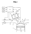
- an internal combustion engine is generally indicated by 1 and includes intake valve 3 and exhaust valve 4.
- An intake valve control apparatus includes first variable valve operating mechanism (VEL) 5 capable of varying (increasing or decreasing) a lift and operation angle of intake valve 3 continuously and second variable valve operating mechanism (VTC) 6 capable of varying (advancing or retarding) a center phase of an operation angle of intake valve 3 continuously.
- VEL variable valve operating mechanism
- VTC variable valve operating mechanism
- At intake passage 7 is dispose electronically controlled throttle valve 2 whose opening degree is controlled by an actuator such as a motor.
- throttle valve 2 is used only for producing a small vacuum (e.g., -50 mmHg) that is required for blow-by gas processing and the intake air amount is basically or mainly controlled by varying the valve lift characteristics of intake valve 3 by means of first and second variable valve operating mechanisms 5, 6.
- An actual throttle-less operation in which the intake air amount is controlled without depending upon the opening degree of throttle valve 2 is thus realized by first and second variable valve operating mechanisms 5, 6.
- First and second variable valve operating mechanisms 5, 6 and electronically controlled throttle valve 2 are controlled by control unit 10.
- fuel injection valve 8 is Further disposed at intake passage 7 is fuel injection valve 8 from which is injected an amount of fuel that is determined in accordance with an intake air amount.
- the intake air amount is controlled by intake valve 3 as described above. Accordingly, the output of internal combustion engine 1 is controlled by controlling the intake air amount by means of first and second variable valve operating mechanisms 5, 6.
- control unit 10 Inputted to control unit 10 are an accelerator opening degree signal APO from accelerator opening degree sensor 11 that is disposed at an accelerator pedal (not shown) operated by a vehicle driver, an engine speed signal Ne from engine speed sensor 12, an intake air amount signal from intake air amount sensor 13, etc.
- Control unit 10 calculates, based on the signals described above, a fuel injection amount, ignition timing, throttle valve opening degree, operation angle target value, maximum lift phase target value, etc. and controls fuel injection valve 8, ignition plug 9, throttle valve 2, first and second variable valve operating mechanisms 5, 6, etc. Further, though not shown, a starter motor is provided, and control unit 10 executes a predetermined engine start control including cranking in response to an input signal from a starter switch or key switch (not shown).
- First and second variable valve operating mechanisms 5, 6 are known and have, for example, substantially the same mechanical structure as those disclosed in Unexamined Japanese Patent Publication No. 2002-256905. Accordingly, first and second variable valve operating mechanisms 5, 6 will be described briefly with reference to FIG. 2.
- Variable valve operating mechanism 5 for variably controlling the lift and operation angle of intake valve 3 includes drive shaft 22 driven by a crankshaft (not shown) of engine 1, circular drive cam 23 eccentrically and fixedly mounted on drive shaft 22 so as to be rotatable together with drive shaft 22, pivotal link 24 pivotally mounted on drive cam 23, control shaft 32 rotatably supported on a cylinder head (not shown) of engine 1, circular control cam 38 eccentrically and fixedly mounted on control shaft 22 so as to be rotatable together with control shaft 22, rocker arm 26 pivotally mounted on control cam 38 and having an end portion pivotally connected to a protruded arm portion of pivotal link 24 by way of connecting pin 35, oscillation cam 29 fixedly mounted on drive shaft 22 for driving intake valve 3 by way of valve lifter 30, and connecting link 28 having an upper end portion pivotally connected to another end portion of rocker arm 26 by way of connecting pin 27 and a lower end portion pivotally connected to oscillation cam 29 by way of connecting pin 37.
- Drive cam 23 has a cylindrical outer periphery which is eccentric with drive shaft 22.
- Control cam 38 has a cylindrical outer periphery which is eccentric with control shaft 32. Accordingly, an oscillation center of rocker arm 26 varies depending upon a variation of an angular position of control shaft 32.
- Oscillation cam 29 has at a lower side thereof a basic circular surface and a cam surface extending continuously from the basic circular surface so as to generate a predetermined curve.
- the basic circular surface and cam surface are selectively brought into contact with the upper surface of valve lifter 30 in dependence upon an oscillated position of oscillation cam 29.
- the basic circular surface defines a reference circular range for making the valve lift zero.
- Actuator 33 for control of lift and operation angle is disposed at an end of control shaft 32.
- Control shaft 32 is driven by actuator 33 so as to be rotatable within a predetermined angular range.
- Actuator 33 for example, consists of an electric motor for driving control shaft 32 by way of worm gear 35 and is controlled by a control signal supplied thereto from control unit 10. The angular position of control shaft 32 is detected by control shaft sensor 34.
- variable valve operating mechanism 5 By first variable valve operating mechanism 5 described above, the lift and operation angle of intake valve 3 are both varied simultaneously and continuously depending upon a variation of the angular position of control shaft 32. Depending upon a variation of the lift and operation angle, the opening and closing timings of intake valve 3 are varied symmetrically about the maximum lift phase or the center phase of the operation angle. The amount of lift and operation angle is determined simply by the angular position of control shaft 32 so that the detection value of control shaft sensor 34 represents the actual lift and operation angle at that time.
- a minimum lift and operation angle corresponds to a start stage lift and operation angle (i.e., a lift and operation angle that should be attained at engine start for attaining valve lift characteristics suitable for starting).
- a holding mechanism 14 consisting of a lock pin, etc. for holding control shaft 32 at an angular position where the lift and operation angle become minimum.
- the lock pin of holding mechanism 14 is, for example, lockingly engaged with control shaft 32 when control shaft 32, after stoppage of engine 1, is driven into an angular position where the lift and operation angle become minimum and disengaged therefrom by means of a solenoid or the like after complete combustion of engine.
- variable valve operating mechanism 6 for variably controlling the maximum lift phase of intake valve 3 includes sprocket 42 disposed at a front end of control shaft 22 and phase control actuator 43 for causing sprocket 42 and drive shaft 22 to rotate relative to each other within a predetermined angular range.
- Sprocket 42 is connected to the crankshaft by way of a timing chain or belt (not shown) so as to be rotatable in timed relation with the crankshaft.
- Phase control actuator 43 in this embodiment is constituted by a hydraulic rotary actuator and controlled by a hydraulic control valve (not shown) in response to a control signal from control unit 10.
- phase control actuator 43 By the operation of phase control actuator 43, sprocket 42 and drive shaft 22 are rotated relative to each other to thereby advance or retard the maximum lift phase of intake valve 3.
- the lift characteristic curve itself is not changed but is moved in its entirety so as to allow the maximum lift phase to advance or retard. Further, the maximum lift phase is also varied continuously.
- the controlled condition of second variable valve operating mechanism 6 is detected by drive shaft sensor 36 that is responsive to the angular position of control shaft 22.
- the most retarded maximum lift phase is used as a start stage maximum lift phase (i.e., a maximum lift phase that should be attained at engine start for attaining valve lift characteristics suitable for starting).
- a start stage maximum lift phase i.e., a maximum lift phase that should be attained at engine start for attaining valve lift characteristics suitable for starting.
- holding mechanism 15 consisting of a lock pin or the like for holding sprocket 42 and drive shaft 22 at such positions that cause the maximum lift phase to retard maximumly.
- the lock pin constituting holding mechanism 15 is engaged with control shaft 22 when control shaft 22 is rotated relative to sprocket 42 into a maximumly retarded position and disengaged therefrom when hydraulic pressure is supplied to holding mechanism 15 after start of engine 1.
- FIG. 3 shows valve lift characteristics of intake valve under a representative engine operating condition.
- the lift and operation angle become minimum and the maximum lift phase is placed at a most advanced phase position.
- the closing timing occurs at a point immediately before the BDC.
- the valve lift characteristics for start stage are the same as those for idling stage so that cranking is performed under the minimum operation angle that is used as the start stage operation angle and under the most retarded maximum lift phase that is used as the start stage maximum lift phase.
- the lift and operation angle becomes large and the maximum lift phase is placed at an advanced phase position. In this instance, by advancing the intake valve closing timing, the intake air amount is controlled to be relatively small.
- the lift and operation angle is increased further and the maximum lift phase is advanced.
- the maximum lift phase is most advanced at a certain point in the middle load range.
- second variable valve operating mechanism 6 is controlled so that the lift and operation angle are increased further and the valve timings become optimum.
- the optimum valve lift characteristics vary depending upon a variation of engine speed.
- FIG. 4 is a flowchart showing a control at engine start according to a first embodiment of the present invention.
- the key switch (not shown) is turned through an ON position into a start position, cranking by a starter motor is started and the control routine of FIG. 4 is started.
- step S1 the maximum lift phase at that time, i.e., the phase position of second variable valve operating mechanism 6 at that time is read.
- step 2 it is determined whether or not the maximum lift phase is at a predetermined start stage phase position (i.e., most retarded phase position), i.e., it is determined whether or not second variable valve operating mechanism 6 is at a predetermined start stage phase position.
- step S3 correction of the operation angle, more specifically, increase-correction of the operation angle is performed.
- FIG. 5 shows a time chart of the operation of the first embodiment and comparatively shows variations of the engine speed, operation angle and maximum lift phase when the engine is restarted after once stopped.
- the solid line indicates a normal operation and the dotted line indicates an abnormal operation to which the processing of this embodiment is applied.
- first variable valve operating mechanism 5 is always urged by the valve spring reaction force in the direction to decrease the lift and operation angle and therefore caused to attain the minimum operation angle rapidly after stoppage of engine. Accordingly, next start of engine is normally performed under such a minimum operation angle and most retarded maximum lift phase.
- first variable valve operating mechanism 5 that varies the operation angle is controlled by an electric motor and therefore can vary the operation angle assuredly even under the condition where the hydraulic pressure is low.
- FIG. 6 shows a variant of the first embodiment.
- step S3 increase-correction of the operation angle is started.
- step S4 it is determined whether or not the operation angle has reached a predetermined value, i.e., whether the phase position of variable valve operating mechanism 5 has reached a predetermined control position. If it is determined that the phase position of variable valve operating mechanism 5 has reached the predetermined control position, the control proceeds to step S5 where injection of fuel is started. In other words, until increase-correction of the operation angle is completed to some extent, injection of fuel is inhibited. By this, it becomes possible to prevent the exhaust gas composition from being deteriorated and the startability from being deteriorated due to excessively rich air/fuel mixture.
- FIG. 7 is a flowchart showing a control at engine start according to a second embodiment.
- the operation angle at that time i.e., the phase position of first variable valve operating mechanism 5 at that time is read.
- step S12 it is determined whether or not the operation angle is a predetermined start stage operation angle (i.e., minimum operation angle), i.e., it is determined whether or not first variable valve operating mechanism 5 is at a predetermined start stage phase position.
- the control proceeds to step S3 where correction of the operation angle, more specifically, increase-correction of the operation angle is performed. The more the actual operation angle is deviated from the operation angle at engine start, the more the correction amount is increased.
- FIG. 8 is a time chart of an operation of second embodiment 6 and comparatively shows variations of the engine speed, operation angle and maximum lift phase when the engine is restarted after once stopped.
- the normal operation is indicated by the solid line, while the abnormal operation to which the processing of this embodiment is applied is indicated by the dotted line.
- first variable valve operation mechanism 5 cannot return to the proper minimum operation angle position due to friction or the like.
- first variable valve operation angle 5 is held as it is without being subjected to any processing, the intake valve closing timing is excessively delayed from the BDC and a predetermined effective compression ratio is also not attained at restart of engine, thus deteriorating the engine startability.
- the maximum lift phase is advance-corrected during cranking as indicated by the dotted line for thereby making the intake valve closing timing go closer to the BDC. By this, a good engine startability is attained.
- start of cranking causes the friction coefficient of first variable valve operating mechanism 5 to decrease so that the actual operation angle starts moving toward the proper target value after start of cranking.
- FIG. 9 is a flowchart showing a control at engine start according to a third embodiment.
- the operation angle and the maximum lift phase are read at engine start (steps S21, S22) . From the relation between them is calculated the intake valve closing timing (S23).
- step S24 by comparing the thus estimated intake valve closing timing with a predetermined start stage closing timing, it is determined whether the estimated intake valve closing timing is on the advance side or on the retard side of the predetermined start stage closing timing.
- the operation angle and the maximum lift phase at engine start that are to be read in steps 21, 22, can be used the values that are read and stored at last stoppage of engine 1.
- step S24 If it is determined in step S24 that the intake valve closing timing is deviated to the advance side, the control proceeds to step S25 where the operation angle target value is increase-corrected and then to step S26 where the maximum lift phase is retard-corrected. By this, the actual intake valve closing timing is retarded and caused to go closer to the proper closing timing at engine start. On the other hand, if it is determined in step S24 that the intake valve closing timing is deviated to the retard side, the control proceeds to step S27 where the operation angle target value is decrease-corrected and to the step S28 where the maximum lift phase is advance-corrected. By this, the actual intake valve closing timing is advanced and caused to go closer to the proper closing timing at engine start. Accordingly, a proper effective compression ratio is attained, thus enabling assured engine start.
- an important feature of the present invention resides in utilizing the fact that the operation angle and the maximum lift phase are controlled by the first and second variable valve operating mechanisms and control, when the phase position of one of the variable valve operating mechanisms is deviated from a predetermined start stage phase position, the other of the valve operating mechanisms so that the valve lift characteristics go closer to those necessary for engine start.
- the operation angle is corrected in accordance with a present maximum lift phase.
- the present operation angle is on the advance side of the predetermined start stage operation angle, the operation angle is increase-corrected.
- the start stage operation angle is generally set small. Thus, if the maximum lift phase is advanced more than the start stage maximum lift phase, the intake valve closing timing is excessively advanced from the BDC, thus disabling to attain an effective compression ratio necessary for engine start. In contrast to this, according to the present invention, the operation angle is increase-corrected to cause the intake valve closing timing to go closer to the BDC, thus causing the effective compression ration to become higher.
- the operation angle after increase-correction thereof may be limited to a predetermined operation angle smaller than the maximum operation angle of the first variable valve operating mechanism. If the operation angle is increase-corrected under a condition of the maximum lift phase being advanced, there can possibly occur such a case in which the intake valve closing timing is advanced largely from the TDC (Top Dead Center). Thus, it is desirable to limit the operation angle after correction for avoiding an excessive valve overlap and an interference between a piston and an intake valve.
- the most retarded maximum lift phase of the first variable valve operating mechanism at the most retarded phase position can be determined as the start stage maximum lift phase. It is desirable that the intake valve control apparatus is provided with a holding mechanism for fixedly holding the second variable valve operating mechanism at the most retarded phase position during engine stoppage.
- the holding mechanism can be used a lock pin or the like that is disengaged in response to oil pressure that is generated when the engine is started.
- the maximum lift phase at engine start may be detected actually at engine start. Otherwise, the maximum lift phase at engine stoppage may be stored in a memory device and the maximum lift phase stored in the memory device is regarded as the present maximum lift phase to perform correction of the operation angle. In this instance, without waiting for detection of the actual position, it is possible to start correction of the operation angle.
- the present operation angle is larger than the start stage operation angle
- correction of the maximum lift phase is performed.
- the intake valve closing timing is set by the start stage operation angle and the start stage maximum lift phase so as to be adjacent the BDC
- an operation angle larger than the start stage operation angle causes the intake valve closing timing to be excessively delayed contrary to the case described above, thus lowering the effective compression ratio.
- the maximum lift phase is advance-corrected to cause the intake valve closing timing to go closer to the BDC, thus making higher the effective compression ratio.
- the operation angle after the advance correction may be limited so as to be within a predetermined advance range on the retard side of the most advanced maximum lift phase of the second variable valve operating mechanism. If the maximum lift phase is advance-corrected under a condition of the operation angle being large, there may possibly occur such a case in which the intake valve closing timing is largely advanced from the TDC. Thus, it is desirable to limit the maximum lift phase after correction so as to avoid an excessively large valve overlap and an interference between a piston and an intake valve.
- the minimum operation angle of the first variable valve operating mechanism can be regarded as the above-described start stage operation angle. It is desirable the intake valve control apparatus is provided with a holding mechanism for fixedly holding the first variable valve operating mechanism at the minimum operation angle position during engine stoppage.
- the holding mechanism can be used a lock pin or the like that is disengaged in response to oil pressure that is generated when the engine is started.
- the operation angle at engine start may be detected actually at engine start. Otherwise, the operation angle at engine stoppage may be stored in a memory device and the operation angle stored in the memory device is regarded as the present operation angle to perform correction of the maximum lift phase. In this instance, without waiting for detection of the actual position, it is possible to start correction of the maximum lift phase.
- the present invention it is desirable to perform correction of the phase positions of the variable valve operating mechanisms during cranking by a starter motor. Even if the first and second variable valve operating mechanisms are in a condition of being not easily movable due to static friction coefficient of each section of the mechanisms before cranking, the mechanisms becomes smoothly movable during cranking and can be rapidly put into a condition of being ready for engine start.
- a further feature of the present invention is to perform correction of both the first and second variable valve operating mechanisms based on the intake valve closing timing at engine start, that is determined by the operation angle and the maximum lift phase.
Landscapes
- Engineering & Computer Science (AREA)
- Mechanical Engineering (AREA)
- General Engineering & Computer Science (AREA)
- Chemical & Material Sciences (AREA)
- Combustion & Propulsion (AREA)
- Output Control And Ontrol Of Special Type Engine (AREA)
- Valve Device For Special Equipments (AREA)
- Electrical Control Of Air Or Fuel Supplied To Internal-Combustion Engine (AREA)
- Combined Controls Of Internal Combustion Engines (AREA)
Applications Claiming Priority (2)
| Application Number | Priority Date | Filing Date | Title |
|---|---|---|---|
| JP2004077507A JP4396339B2 (ja) | 2004-03-18 | 2004-03-18 | 内燃機関の吸気弁駆動制御装置 |
| JP2004077507 | 2004-03-18 |
Publications (3)
| Publication Number | Publication Date |
|---|---|
| EP1577511A2 true EP1577511A2 (fr) | 2005-09-21 |
| EP1577511A3 EP1577511A3 (fr) | 2006-02-01 |
| EP1577511B1 EP1577511B1 (fr) | 2007-04-25 |
Family
ID=34836566
Family Applications (1)
| Application Number | Title | Priority Date | Filing Date |
|---|---|---|---|
| EP05005069A Not-in-force EP1577511B1 (fr) | 2004-03-18 | 2005-03-08 | Moyen et méthode de commande de soupape d'admission pour moteur à combustion interne |
Country Status (4)
| Country | Link |
|---|---|
| US (1) | US7168402B2 (fr) |
| EP (1) | EP1577511B1 (fr) |
| JP (1) | JP4396339B2 (fr) |
| DE (1) | DE602005000946T2 (fr) |
Cited By (5)
| Publication number | Priority date | Publication date | Assignee | Title |
|---|---|---|---|---|
| WO2006080472A1 (fr) * | 2005-01-31 | 2006-08-03 | Toyota Jidosha Kabushiki Kaisha | Appareil de commande pour moteur a combustion interne |
| EP1703104A1 (fr) * | 2005-02-25 | 2006-09-20 | Toyota Jidosha Kabushiki Kaisha | Dispositif et procédé de commande pour controler un dispositif de distribution variable pour un moteur à combustion interne |
| WO2008068985A1 (fr) * | 2006-12-04 | 2008-06-12 | Toyota Jidosha Kabushiki Kaisha | Moteur à combustion interne doté d'un allumage de type à bougie |
| EP2096281A1 (fr) * | 2008-02-28 | 2009-09-02 | Mazda Motor Corporation | Procédé de contrôle de moteur à combustion interne, système de moteur à combustion interne et produit de programme informatique correspondant |
| CN102348884A (zh) * | 2009-03-09 | 2012-02-08 | 日产自动车株式会社 | 混合式车辆 |
Families Citing this family (12)
| Publication number | Priority date | Publication date | Assignee | Title |
|---|---|---|---|---|
| US7079935B2 (en) * | 2004-03-19 | 2006-07-18 | Ford Global Technologies, Llc | Valve control for an engine with electromechanically actuated valves |
| JP4497089B2 (ja) * | 2005-12-13 | 2010-07-07 | トヨタ自動車株式会社 | 内燃機関の制御装置 |
| JP4776447B2 (ja) | 2006-06-12 | 2011-09-21 | 日立オートモティブシステムズ株式会社 | 内燃機関の可変動弁装置 |
| JP4907416B2 (ja) | 2007-04-23 | 2012-03-28 | 日立オートモティブシステムズ株式会社 | 内燃機関の可変動弁装置 |
| JP2009074414A (ja) | 2007-09-20 | 2009-04-09 | Hitachi Ltd | 内燃機関の可変動弁システム及び可変動弁装置 |
| US7881856B2 (en) * | 2008-04-03 | 2011-02-01 | Hitachi, Ltd. | Apparatus for and method of controlling fuel injection of engine |
| JP4858729B2 (ja) * | 2008-11-12 | 2012-01-18 | 三菱自動車工業株式会社 | 可変動弁装置 |
| JP5532953B2 (ja) * | 2010-01-21 | 2014-06-25 | トヨタ自動車株式会社 | 可変動弁システムの制御装置 |
| JP5402984B2 (ja) * | 2011-05-18 | 2014-01-29 | 株式会社デンソー | 可変バルブタイミング制御装置 |
| JP6281559B2 (ja) | 2015-06-05 | 2018-02-21 | 株式会社デンソー | 内燃機関のバルブタイミング制御用モータ駆動装置 |
| WO2016194281A1 (fr) * | 2015-06-05 | 2016-12-08 | 株式会社デンソー | Dispositif d'entraînement de moteur pour commander le calage de soupape d'un moteur à combustion interne |
| DE102015224758A1 (de) * | 2015-12-10 | 2017-06-14 | Bayerische Motoren Werke Aktiengesellschaft | Verfahren zum Starten eines Verbrennungsmotors |
Citations (4)
| Publication number | Priority date | Publication date | Assignee | Title |
|---|---|---|---|---|
| EP1164259A1 (fr) * | 2000-06-12 | 2001-12-19 | Nissan Motor Company, Limited | Système de distribution variable d'un moteur à combustion interne, qui permet de varier la phase et la durée d'ouverture |
| US6401675B1 (en) * | 1999-02-15 | 2002-06-11 | Unisia Jecs Corporation | Variable valve gear device of internal combustion engine |
| JP2002256905A (ja) * | 2001-02-27 | 2002-09-11 | Nissan Motor Co Ltd | 内燃機関の吸気制御装置 |
| EP1403487A2 (fr) * | 2002-09-24 | 2004-03-31 | Nissan Motor Company, Limited | Dispositif de controle et procéde pour un moteur avec un VVT |
Family Cites Families (1)
| Publication number | Priority date | Publication date | Assignee | Title |
|---|---|---|---|---|
| JP4373028B2 (ja) * | 2001-05-09 | 2009-11-25 | 日立オートモティブシステムズ株式会社 | 内燃機関の可変動弁装置及びその制御方法 |
-
2004
- 2004-03-18 JP JP2004077507A patent/JP4396339B2/ja not_active Expired - Fee Related
-
2005
- 2005-03-08 EP EP05005069A patent/EP1577511B1/fr not_active Not-in-force
- 2005-03-08 DE DE602005000946T patent/DE602005000946T2/de active Active
- 2005-03-08 US US11/073,614 patent/US7168402B2/en active Active
Patent Citations (5)
| Publication number | Priority date | Publication date | Assignee | Title |
|---|---|---|---|---|
| US6401675B1 (en) * | 1999-02-15 | 2002-06-11 | Unisia Jecs Corporation | Variable valve gear device of internal combustion engine |
| US6513469B2 (en) * | 1999-02-15 | 2003-02-04 | Unisia Jecs Corporation | Variable valve operating system of internal combustion engine |
| EP1164259A1 (fr) * | 2000-06-12 | 2001-12-19 | Nissan Motor Company, Limited | Système de distribution variable d'un moteur à combustion interne, qui permet de varier la phase et la durée d'ouverture |
| JP2002256905A (ja) * | 2001-02-27 | 2002-09-11 | Nissan Motor Co Ltd | 内燃機関の吸気制御装置 |
| EP1403487A2 (fr) * | 2002-09-24 | 2004-03-31 | Nissan Motor Company, Limited | Dispositif de controle et procéde pour un moteur avec un VVT |
Non-Patent Citations (1)
| Title |
|---|
| PATENT ABSTRACTS OF JAPAN vol. 2003, no. 01, 14 January 2003 (2003-01-14) & JP 2002 256905 A (NISSAN MOTOR CO LTD), 11 September 2002 (2002-09-11) & EP 1 234 958 A (NISSAN MOTOR CO., LTD) 28 August 2002 (2002-08-28) * |
Cited By (10)
| Publication number | Priority date | Publication date | Assignee | Title |
|---|---|---|---|---|
| WO2006080472A1 (fr) * | 2005-01-31 | 2006-08-03 | Toyota Jidosha Kabushiki Kaisha | Appareil de commande pour moteur a combustion interne |
| US7814743B2 (en) | 2005-01-31 | 2010-10-19 | Toyota Jidosha Kabushiki Kaisha | Control apparatus for internal combustion engine |
| EP1703104A1 (fr) * | 2005-02-25 | 2006-09-20 | Toyota Jidosha Kabushiki Kaisha | Dispositif et procédé de commande pour controler un dispositif de distribution variable pour un moteur à combustion interne |
| US7316210B2 (en) | 2005-02-25 | 2008-01-08 | Toyota Jidosha Kabushiki Kaisha | Control apparatus and control method for variable valve actuation mechanism of internal combustion engine |
| WO2008068985A1 (fr) * | 2006-12-04 | 2008-06-12 | Toyota Jidosha Kabushiki Kaisha | Moteur à combustion interne doté d'un allumage de type à bougie |
| US8234054B2 (en) | 2006-12-04 | 2012-07-31 | Toyota Jidosha Kabushiki Kaisha | Method of operating a spark ignition type internal combustion engine |
| EP2096281A1 (fr) * | 2008-02-28 | 2009-09-02 | Mazda Motor Corporation | Procédé de contrôle de moteur à combustion interne, système de moteur à combustion interne et produit de programme informatique correspondant |
| CN102348884A (zh) * | 2009-03-09 | 2012-02-08 | 日产自动车株式会社 | 混合式车辆 |
| CN102348884B (zh) * | 2009-03-09 | 2014-03-26 | 日产自动车株式会社 | 发动机控制设备和包括该发动机控制设备的混合式车辆 |
| US9322353B2 (en) | 2009-03-09 | 2016-04-26 | Nissan Motor Co., Ltd. | Engine control apparatus and hybrid vehicle including thereof |
Also Published As
| Publication number | Publication date |
|---|---|
| EP1577511B1 (fr) | 2007-04-25 |
| JP4396339B2 (ja) | 2010-01-13 |
| JP2005264804A (ja) | 2005-09-29 |
| DE602005000946D1 (de) | 2007-06-06 |
| DE602005000946T2 (de) | 2007-09-06 |
| US20050205029A1 (en) | 2005-09-22 |
| US7168402B2 (en) | 2007-01-30 |
| EP1577511A3 (fr) | 2006-02-01 |
Similar Documents
| Publication | Publication Date | Title |
|---|---|---|
| EP1577511B1 (fr) | Moyen et méthode de commande de soupape d'admission pour moteur à combustion interne | |
| US6705257B2 (en) | Apparatus and method for controlling variable valve in internal combustion engine | |
| US7191746B2 (en) | Engine start control apparatus | |
| US7789051B2 (en) | Variable valve actuating apparatus for internal combustion engine | |
| US7021258B2 (en) | Learning apparatus and method for variable valve control of internal combustion engine | |
| EP1293659B1 (fr) | Méthode et système de commande pour un moteur à combustion interne | |
| US7481199B2 (en) | Start control apparatus of internal combustion engine | |
| US7426913B2 (en) | Intake valve control system and method for internal combustion engine | |
| EP1344897A2 (fr) | Dispositif et méthode de commande variable des soupapes utilisent une signal de température pour un moteur à combustion interne | |
| JP2003065089A (ja) | 内燃機関の可変動弁装置 | |
| JP5668458B2 (ja) | 内燃機関の制御装置 | |
| JP4136926B2 (ja) | 内燃機関の始動制御装置及び始動制御方法 | |
| US6915769B2 (en) | Variable valve system for internal combustion engine | |
| JP4525406B2 (ja) | 内燃機関のバルブ特性制御装置 | |
| JP5035317B2 (ja) | 内燃機関の制御方法及び内燃機関システム | |
| JP4697485B2 (ja) | 内燃機関の始動制御装置 | |
| JP5515793B2 (ja) | 内燃機関の可変機構制御システム | |
| JP4765699B2 (ja) | レシプロ式内燃機関の制御方法 | |
| JP2008291852A (ja) | 内燃機関の吸気弁駆動制御装置 | |
| JP4525557B2 (ja) | 内燃機関の制御装置 | |
| JP4507693B2 (ja) | 内燃機関の制御装置 | |
| JP4432746B2 (ja) | 内燃機関の吸気制御装置 | |
| JP4428219B2 (ja) | 可変動弁機構の制御装置 | |
| JP4136161B2 (ja) | 内燃機関の可変動弁装置 | |
| JP4661646B2 (ja) | 内燃機関の制御装置 |
Legal Events
| Date | Code | Title | Description |
|---|---|---|---|
| PUAI | Public reference made under article 153(3) epc to a published international application that has entered the european phase |
Free format text: ORIGINAL CODE: 0009012 |
|
| 17P | Request for examination filed |
Effective date: 20050308 |
|
| AK | Designated contracting states |
Kind code of ref document: A2 Designated state(s): AT BE BG CH CY CZ DE DK EE ES FI FR GB GR HU IE IS IT LI LT LU MC NL PL PT RO SE SI SK TR |
|
| AX | Request for extension of the european patent |
Extension state: AL BA HR LV MK YU |
|
| PUAL | Search report despatched |
Free format text: ORIGINAL CODE: 0009013 |
|
| AK | Designated contracting states |
Kind code of ref document: A3 Designated state(s): AT BE BG CH CY CZ DE DK EE ES FI FR GB GR HU IE IS IT LI LT LU MC NL PL PT RO SE SI SK TR |
|
| AX | Request for extension of the european patent |
Extension state: AL BA HR LV MK YU |
|
| RIC1 | Information provided on ipc code assigned before grant |
Ipc: F02D 13/02 20060101ALI20051214BHEP Ipc: F02N 17/00 20060101ALI20051214BHEP Ipc: F01L 13/00 20060101AFI20050704BHEP Ipc: F01L 1/34 20060101ALI20051214BHEP Ipc: F02D 41/00 20060101ALI20051214BHEP |
|
| GRAP | Despatch of communication of intention to grant a patent |
Free format text: ORIGINAL CODE: EPIDOSNIGR1 |
|
| AKX | Designation fees paid |
Designated state(s): DE FR GB |
|
| GRAS | Grant fee paid |
Free format text: ORIGINAL CODE: EPIDOSNIGR3 |
|
| GRAA | (expected) grant |
Free format text: ORIGINAL CODE: 0009210 |
|
| AK | Designated contracting states |
Kind code of ref document: B1 Designated state(s): DE FR GB |
|
| REG | Reference to a national code |
Ref country code: GB Ref legal event code: FG4D |
|
| REF | Corresponds to: |
Ref document number: 602005000946 Country of ref document: DE Date of ref document: 20070606 Kind code of ref document: P |
|
| ET | Fr: translation filed | ||
| PLBE | No opposition filed within time limit |
Free format text: ORIGINAL CODE: 0009261 |
|
| STAA | Information on the status of an ep patent application or granted ep patent |
Free format text: STATUS: NO OPPOSITION FILED WITHIN TIME LIMIT |
|
| 26N | No opposition filed |
Effective date: 20080128 |
|
| REG | Reference to a national code |
Ref country code: FR Ref legal event code: PLFP Year of fee payment: 12 |
|
| PGFP | Annual fee paid to national office [announced via postgrant information from national office to epo] |
Ref country code: DE Payment date: 20160302 Year of fee payment: 12 |
|
| PGFP | Annual fee paid to national office [announced via postgrant information from national office to epo] |
Ref country code: GB Payment date: 20160302 Year of fee payment: 12 Ref country code: FR Payment date: 20160208 Year of fee payment: 12 |
|
| REG | Reference to a national code |
Ref country code: DE Ref legal event code: R119 Ref document number: 602005000946 Country of ref document: DE |
|
| GBPC | Gb: european patent ceased through non-payment of renewal fee |
Effective date: 20170308 |
|
| REG | Reference to a national code |
Ref country code: FR Ref legal event code: ST Effective date: 20171130 |
|
| PG25 | Lapsed in a contracting state [announced via postgrant information from national office to epo] |
Ref country code: DE Free format text: LAPSE BECAUSE OF NON-PAYMENT OF DUE FEES Effective date: 20171003 Ref country code: FR Free format text: LAPSE BECAUSE OF NON-PAYMENT OF DUE FEES Effective date: 20170331 |
|
| PG25 | Lapsed in a contracting state [announced via postgrant information from national office to epo] |
Ref country code: GB Free format text: LAPSE BECAUSE OF NON-PAYMENT OF DUE FEES Effective date: 20170308 |