EP1577465A1 - Élément de verrouillage avec fixation pour élément d'actionnement - Google Patents
Élément de verrouillage avec fixation pour élément d'actionnement Download PDFInfo
- Publication number
- EP1577465A1 EP1577465A1 EP05004590A EP05004590A EP1577465A1 EP 1577465 A1 EP1577465 A1 EP 1577465A1 EP 05004590 A EP05004590 A EP 05004590A EP 05004590 A EP05004590 A EP 05004590A EP 1577465 A1 EP1577465 A1 EP 1577465A1
- Authority
- EP
- European Patent Office
- Prior art keywords
- lock body
- lock
- locking
- spring
- cylindrical
- Prior art date
- Legal status (The legal status is an assumption and is not a legal conclusion. Google has not performed a legal analysis and makes no representation as to the accuracy of the status listed.)
- Granted
Links
- 230000005540 biological transmission Effects 0.000 claims description 7
- 238000006073 displacement reaction Methods 0.000 claims description 5
- 238000003780 insertion Methods 0.000 claims description 3
- 230000037431 insertion Effects 0.000 claims description 3
- 230000002093 peripheral effect Effects 0.000 abstract 1
- 239000002184 metal Substances 0.000 description 7
- 238000005553 drilling Methods 0.000 description 3
- 238000009434 installation Methods 0.000 description 3
- 238000010276 construction Methods 0.000 description 2
- CVOFKRWYWCSDMA-UHFFFAOYSA-N 2-chloro-n-(2,6-diethylphenyl)-n-(methoxymethyl)acetamide;2,6-dinitro-n,n-dipropyl-4-(trifluoromethyl)aniline Chemical compound CCC1=CC=CC(CC)=C1N(COC)C(=O)CCl.CCCN(CCC)C1=C([N+]([O-])=O)C=C(C(F)(F)F)C=C1[N+]([O-])=O CVOFKRWYWCSDMA-UHFFFAOYSA-N 0.000 description 1
- 230000000295 complement effect Effects 0.000 description 1
- 230000008878 coupling Effects 0.000 description 1
- 238000010168 coupling process Methods 0.000 description 1
- 238000005859 coupling reaction Methods 0.000 description 1
- 210000003746 feather Anatomy 0.000 description 1
- 230000003993 interaction Effects 0.000 description 1
- 230000013011 mating Effects 0.000 description 1
- 230000003716 rejuvenation Effects 0.000 description 1
Images

Classifications
-
- E—FIXED CONSTRUCTIONS
- E05—LOCKS; KEYS; WINDOW OR DOOR FITTINGS; SAFES
- E05B—LOCKS; ACCESSORIES THEREFOR; HANDCUFFS
- E05B3/00—Fastening knobs or handles to lock or latch parts
- E05B3/04—Fastening the knob or the handle shank to the spindle by screws, springs or snap bolts
-
- E—FIXED CONSTRUCTIONS
- E05—LOCKS; KEYS; WINDOW OR DOOR FITTINGS; SAFES
- E05B—LOCKS; ACCESSORIES THEREFOR; HANDCUFFS
- E05B9/00—Lock casings or latch-mechanism casings ; Fastening locks or fasteners or parts thereof to the wing
- E05B9/04—Casings of cylinder locks
- E05B9/041—Double cylinder locks
-
- E—FIXED CONSTRUCTIONS
- E05—LOCKS; KEYS; WINDOW OR DOOR FITTINGS; SAFES
- E05B—LOCKS; ACCESSORIES THEREFOR; HANDCUFFS
- E05B9/00—Lock casings or latch-mechanism casings ; Fastening locks or fasteners or parts thereof to the wing
- E05B9/04—Casings of cylinder locks
- E05B2009/046—Cylinder locks operated by knobs or handles
Definitions
- the invention relates to a lock element with a lock body, a against the lock body rotatable closing element and a can be coupled with the closing element and with respect to the lock body rotatable actuator.
- Such lock elements come for example in conventional mortise locks used in which a profile cylinder as a lock body and a door handle or doorknob serves as an actuator.
- the actuators At the Installation of such mortise locks in a door is the task the actuators on the simplest possible, space-saving and visually appealing way to attach to the lock body.
- At least up one side of the door lock so an actuator after the Installation of the lock body in the door to be retrofitted.
- an actuator after the Installation of the lock body in the door to be retrofitted.
- electronic locking systems exists in addition the problem that in a e.g. designed as a door knob actuator housed mechanical and electronic components so that comparatively little space for attachment the actuating element is available on the lock body.
- a common solution known from the prior art suggests at least one of the two actuators on one through the Door lock extending shaft to be plugged and with the help of a radially on the shaft-engaging fastener, e.g. to a threaded pin fix.
- this solution is not visually satisfactory because the Fastener visible on the outside of the actuator is.
- a sufficiently stable attachment is a massive wave what is required for mechanical and electronic components for Limited available space.
- Object of the present invention is therefore a lock element of initially provided type, in which an actuating element in a simple and space-saving manner is releasably fastened.
- the lock element has one in the lock body protruding cavity in which the actuator with a cylindrical attachment portion is detachably fastened.
- the cylindrical attachment portion of the actuating element has the outside a circumferential groove which can be latched with a latching element, which is radial to the axis of the cylindrical attachment portion slidably guided in the lock body and by means of a spring in the direction the groove of the actuating element is acted upon.
- the actuator So is by the locking of the groove with the corresponding Locking element secured against axial displacement.
- the cylindrical attachment portion may be at its in the lock body protruding end having a conical taper, which a displacement of the locking element against the spring tension during insertion of the actuating element in the cavity of the lock body allows. If the lock body is already mounted in a door lock, the actuator can thus easily on the lock element be attached. When inserting the actuator with its conically tapered attachment section into the cavity of the Lock body is the force applied during insertion through the inclined surface on the tapered attachment portion in a radially extending force, which can compress the spring converted. When the actuator is inserted far enough into the cavity is, its circumferential groove engages with the locking element, while this is pressed by the spring in the direction of the groove. The Actuator can therefore be attached by simply plugging, without the need for a tool, and at the same time assembly errors reliably avoided.
- the locking element along a running inside the lock body in particular be guided linear guideway, with its movement in two opposite, radially to the axis of the cylindrical mounting portion extending directions by means of stop elements is limited.
- the locking element Along the completely outside the fastener extending guideway is the locking element thus based on the Interior of the fastener space-saving housed and with the help of the stop elements is the way to the locking element displaceable radially to the axis of the cylindrical mounting portion is limited.
- stop elements for example, a provided in the locking element Slot and a provided in the lock body pin, which itself extends through the slot, serve.
- Such a construction is easy to implement and also durable and maintenance-free.
- the spring which the locking element in the direction of the groove of the mounting portion acted upon, in a radially to the axis of the cylindrical attachment portion extending recess of the locking element arranged be.
- the previously mentioned pin, which as a stop element serves, can with a hineinersummenden in this recess Area form a support element for the spring.
- the recess, in the spring is arranged on the surface of the lock body be open, as well as a chamber-like closed recess conceivable.
- both the locking element and the lock body each have a bore on, wherein the two holes at least substantially the same Have diameter and parallel to the axis of the cylindrical mounting portion run.
- the two holes are arranged in such a way that the lock body side bore extends from the end of the Lock body to which the actuator is fastened, up to the Bore of the lock body mounted in the locking element extends, and that the two holes aligned with each other when compressed spring are and overlap partially with relaxed spring. at compressed spring so the two holes are axially behind each other.
- Such a tool resembles a screwdriver with a handle and a round metal rod attached to it.
- the summit this metal rod forms a cylindrical extension whose cross-section smaller than that of the metal rod, and the front end of the Metal rod is arranged eccentrically on this.
- the two holes overlap only partially and an eccentric tool can with its cylindrical extension through the lock body side Bore in the overlap area of the locking element be provided for drilling. If the eccentric tool is now rotated, the locking element of the groove of the mounting portion pulled away and compressed the spring. The two holes are aligned with each other and the locking of the locking element with the actuator is released.
- the diameter of the two parallel to the axis of the cylindrical attachment portion extending holes can each be between 2 mm and 5 mm, in particular about 3 mm.
- the two bores preferably overlap by about half their diameter. In this way, at a reasonable engagement depth between locking element and groove optimum power transmission Attachment of an eccentric tool for releasing the locking achieved.
- the actuator is in the manner explained relatively simple from Lock body solvable, nevertheless offers the fact that to solve the Locking a special tool is needed, some protection against an abusive removal of the actuator. Of special The advantage here is that the actuator mounted as often as desired and can be dismantled without damaging the lock element is or without signs of wear occur.
- the lock element according to the invention can be located centrally in the cavity of the Lock body having rotatably mounted shaft, which at one end rotatably connected to a second actuator, whereas the first actuator a receptacle for the other end of the Wave owns.
- the shaft according to the invention not used to fix the first actuator is, it can also be designed as a hollow shaft, whereby additional Space for electronic components, cables or the like is available.
- the attachment portion may be at its in the cavity of the lock body protruding end frontally a first power transmission element have, which with a corresponding thereto second Power transmission element can be brought into engagement, which in turn rotatably coupled to the closing element.
- Power transmission elements are, for example, a radially extending groove and at least one corresponding projection possible.
- the lock body may, for example, take the form of a commercial, standardized profile cylinder have. Such a lock body can, without that additional adapters are necessary in common door locks with standardized dimensions are used.
- Such a molded lock body consists of an upper portion with a cylindrical cross section and a lower section with a elongated cross-section.
- the one in the lower section of the lock body guided area of the locking element must be in a perpendicular to Narrower longitudinal direction of the lock element extending direction be as the lower portion of the lock body.
- the locking element at its upper end in the circumferential groove of the mounting section mating locking area which, in a direction perpendicular to the longitudinal center plane of the Castle element extending direction a greater ready than the lower Section of the profile cylinder has.
- the area of the groove, with which it engages with the detent element is enlarged in this way, whereby a better grip is achievable.
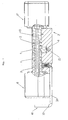
- the lock body 2 shown in Fig. 1 has the outer shape of a Profile cylinder. Approximately in the middle of the lock body 2 is located at the illustrated embodiment, a relation to the lock body rotatable closing element 4 with a cam 6 at its lower The End. In other embodiments, the closure element also be arranged asymmetrically in the lock body.
- the illustrated Lock element 2 has two, each for mounting a door knob suitable actuators 8, 8 'at its two opposite End up.
- the right actuating element 8 ' is non-rotatable with a shaft 18th connected.
- the shaft 18 is centered in a cylindrical cavity. 3 (see Fig. 1B) in the middle of the cylindrical upper portion of the Lock body 2 is arranged and rotatably mounted in the lock body 2.
- the left operating element 8 is suitable, for example, for mounting a door knob.
- a cylindrical Mounting portion 9 which is located inside the cylindrical cavity 3 is located inside the lock body 2 and in turn centrally one Passage space for the shaft 18 has. Through this passageway the shaft 18 extends through the entire attachment portion 9 into the actuating element 8.
- the mounting portion 9 is locked to the lock body 2 and inserted so far into the cavity 3 of the lock body 2, that he abuts the front side of an intermediate ring 7, which in turn is connected non-positively with the closing element 4.
- the cavity 3 is thus almost completely filled by the attachment portion 9.
- a bore 20 is formed, which for Attachment of the lock element in a door by means of a not shown Forend screw is used.
- FIG. 1A the mechanism for latching the operating member 8 shown enlarged in the cavity 3 of the lock body 2.
- the Fig. 1A and 1B respectively show the same section of the lock element 2.
- the latched state shown in FIG. 1 is shown in FIG. 1A shown, while in Fig. 1B, the actuator 8 only partially in the cavity 3 of the lock body 2 is inserted and not yet the locking element 10 is locked.
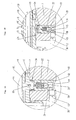
- Fig. 1A one can see the locking element 10, which in a Guide track 32 is guided in the interior of the lock body 2, and radially moved to the axis m of the cylindrical mounting portion 9 can be.
- the locking element 10 has a locking area 16, which is shown in more detail in FIG. 3.
- the locking area 16 is a bolt-like fastener 34 in held the locking element 10.
- the mounting portion 9 of the actuating element 8 has the outside a circumferential groove 24.
- the locking portion 16 of the locking element 9 sits in this groove 24, so that the actuator 8 while to the axis m is rotated, but not moved in the axial direction can.
- a spring 22 is in a circular cross-section recess 30 in Interior of the locking element 10 is arranged, wherein the cross section of the recess 30 substantially corresponds to the diameter of the spring 22.
- the recess 30 is open at the bottom; the spring 22 is with its lower End supported on a pin 14, which is perpendicular to the longitudinal center plane of the lock body 2 by the lower, elongated Area is plugged.
- the pin 14 is in a circular bore held the lock body 2, which has the same diameter as the Pin 14 has.
- the pin 14 extends through a slot 15 in Locking element 10, which is a radial displacement of the locking element 10th allows. By the interaction of slot 15 and pin 14 is the radial displacement of the locking element 10 up and down limited.
- the spring is relaxed and pushes the locking element 10 upwards and thus the locking element 16 in the groove 24. Der Pin 14 touches the upper end of the slot 15 in this position.
- the attachment portion 9 has shown in FIG. 1B at its in the Lock body 2 protruding end face 9 'a conical taper. 5 on.
- holes 12 and 28 can be made recognize which serve to release the explained locking.
- a Bore 12 in the lock body 2 and a bore 28 in the locking element 10th each have the same diameter d and both run parallel to the axis m of the cylindrical mounting portion 9.
- compressed Spring 22 (FIG. 1B) is the bore 12 in the lock body 2 and the Hole 28 in the locking element 10 aligned with each other and thus form a continuous cylindrical bore.
- an eccentric tool 40 may be used to release the locking.
- an eccentric tool 40 can be seen, which is inserted through the bore 12 and into the bore 28.
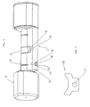
- the tool is shown alone.
- Such a tool consists of a handle 37 and a metal rod 36 with a round Cross-section, wherein the diameter of the rod 36 is approximately the Diameter d of the bores 12, 28 in the lock body 2 and in the locking element 10 must correspond.
- At the front end of the tool there is an eccentrically arranged smaller cylinder extension 38, whose diameter is at most the overlap of the two holes 12, 28 in the state of the lock member shown in Fig. 1A may.
- Fig. 3 the lock element 2 according to the invention is shown in perspective. Through the downwardly open guide track 32 is the locking element 10 recognizable with the downwardly open recess 30 in its center. Above the pin 14 can be seen, which as a stop element serves and at the same time in Fig. 2 not visible spring 22 is supported. The locking portion 16 of the locking element 10 is in a slot-like Recess of the lock body 2 perpendicular to the longitudinal center plane.
- the locking portion 16 of the locking element 10 is increased shown.
- the locking area 16 is a flat one Metal part whose surface is substantially perpendicular to the axis m the cylindrical mounting portion 9 is located.
- the locking portion 16 has a bore 17 through which a Bolt for fixing the locking portion 16 in the locking element 10th can be plugged.
- the locking portion 16 of the locking element 10th is in a direction perpendicular to the longitudinal center plane of the lock element Direction narrower than the lower portion of the lock body. 2 Above this range, the locking portion 16 extends in said Direction sideways and then has a greater width than the lower section of the lock body 2.
- the Locking area 16 crescent-shaped, so that it to the annular groove 24 in the attachment portion 9 is complementary and not at the same time protrudes beyond the outer contour of the lock body 2.
- the invention relates to a lock element with a Lock body 2, one opposite the lock body 2 rotatable Closing element 4 and one projecting into the lock body 2 Cavity 3, in which one can be coupled with the closing element 4 and opposite the lock body 2 rotatable actuator 8 with a cylindrical mounting portion 9 is detachably fastened.
- the attachment section 9 of the actuating element 8 has on the outside a circumferential Groove 24, which can be latched with a locking element 10.
- the Locking element 10 is along a running within the lock body 2 Guided track 32 and radially to the axis m of the cylindrical Fixing portion 9 between two extreme positions displaced. With a spring 22, the locking element 10 in the direction of the groove 24 of the mounting portion 9 biased.
Landscapes
- Engineering & Computer Science (AREA)
- Mechanical Engineering (AREA)
- Lock And Its Accessories (AREA)
- Chairs For Special Purposes, Such As Reclining Chairs (AREA)
- Clamps And Clips (AREA)
- Snaps, Bayonet Connections, Set Pins, And Snap Rings (AREA)
- Portable Nailing Machines And Staplers (AREA)
Applications Claiming Priority (2)
| Application Number | Priority Date | Filing Date | Title |
|---|---|---|---|
| DE102004011449 | 2004-03-09 | ||
| DE102004011449A DE102004011449A1 (de) | 2004-03-09 | 2004-03-09 | Schlosselement |
Publications (2)
| Publication Number | Publication Date |
|---|---|
| EP1577465A1 true EP1577465A1 (fr) | 2005-09-21 |
| EP1577465B1 EP1577465B1 (fr) | 2009-12-23 |
Family
ID=34833108
Family Applications (1)
| Application Number | Title | Priority Date | Filing Date |
|---|---|---|---|
| EP05004590A Active EP1577465B1 (fr) | 2004-03-09 | 2005-03-02 | Élément de verrouillage avec fixation pour élément d'actionnement |
Country Status (6)
| Country | Link |
|---|---|
| EP (1) | EP1577465B1 (fr) |
| AT (1) | ATE453031T1 (fr) |
| DE (2) | DE102004011449A1 (fr) |
| DK (1) | DK1577465T3 (fr) |
| ES (1) | ES2338660T3 (fr) |
| PT (1) | PT1577465E (fr) |
Cited By (2)
| Publication number | Priority date | Publication date | Assignee | Title |
|---|---|---|---|---|
| EP1724417A2 (fr) | 2005-05-19 | 2006-11-22 | Hewi Heinrich Wilke Gmbh | Élément de serrure |
| DE102014110970B3 (de) * | 2014-08-01 | 2015-10-15 | ASTRA Gesellschaft für Asset Management mbH & Co. KG | Schließzylinderanordnung |
Families Citing this family (1)
| Publication number | Priority date | Publication date | Assignee | Title |
|---|---|---|---|---|
| ES2397022B1 (es) * | 2011-02-03 | 2014-01-10 | Salto Systems, S.L. | Sistema de bloqueo y liberación rápido para pomos de seguridad. |
Citations (5)
| Publication number | Priority date | Publication date | Assignee | Title |
|---|---|---|---|---|
| GB853801A (en) * | 1957-03-07 | 1960-11-09 | Heinrich Wilke | Improvements in or relating to door handle assemblies |
| FR1480360A (fr) * | 1966-03-31 | 1967-05-12 | Charles Gabon Ets | Serrure de sécurité |
| GB1126499A (en) * | 1966-06-23 | 1968-09-05 | Grossteinbeck Gmbh Otto | Door handle connection |
| US3504939A (en) * | 1967-04-25 | 1970-04-07 | Wilhelm Engstfeld | Door handle connection |
| JP2002070369A (ja) * | 2000-08-28 | 2002-03-08 | Hokusei Die Cast Kogyo Kk | ハンドル軸とレバーハンドルの連結構造 |
Family Cites Families (11)
| Publication number | Priority date | Publication date | Assignee | Title |
|---|---|---|---|---|
| DE1052855B (de) * | 1956-03-06 | 1959-03-12 | Zeiss Ikon Ag | Einsteckschloss mit beiderseits an die Schliessgliedwelle ankuppelbaren Schlosshandhaben |
| DE1241833B (de) * | 1962-02-07 | 1967-06-08 | Wolfen Filmfab Veb | Verfahren zur Herstellung von 5-Chlor-4-amino-2, 6-dimethylpyrimidin |
| US4639026A (en) * | 1985-10-11 | 1987-01-27 | Schlage Lock Company | Door knob and door knob catch arrangement |
| US5316355A (en) * | 1993-05-13 | 1994-05-31 | Masco Corporation Of Indiana | Integral door knob assembly with spring return |
| DE9414983U1 (de) * | 1994-09-15 | 1994-11-03 | Roto Frank Ag | Bedienungsgriff |
| DE29703559U1 (de) * | 1996-03-27 | 1997-04-30 | Lerchner Leonhard | Türschloß |
| EP0962612A3 (fr) * | 1998-06-03 | 2002-10-16 | DOM Sicherheitstechnik GmbH | Serrure cylindrique |
| DE19918305C2 (de) * | 1999-04-22 | 2001-07-12 | Dom Sicherheitstechnik | Schließzylinder mit zwei drehbar miteinander gekuppelten Antriebselementen und Entkupplungswerkzeug |
| DE19940247A1 (de) * | 1999-08-25 | 2001-03-08 | Winkhaus Fa August | Schließeinrichtung |
| DE20100424U1 (de) * | 2001-01-11 | 2001-03-22 | Schulte Zylinderschl Gmbh | Schließzylinder mit rutschgekuppeltem Drehknopf |
| DE10235201B4 (de) * | 2002-08-01 | 2006-02-16 | Günter Uhlmann | Türschließystem |
-
2004
- 2004-03-09 DE DE102004011449A patent/DE102004011449A1/de not_active Withdrawn
-
2005
- 2005-03-02 DK DK05004590.5T patent/DK1577465T3/da active
- 2005-03-02 ES ES05004590T patent/ES2338660T3/es active Active
- 2005-03-02 DE DE502005008730T patent/DE502005008730D1/de active Active
- 2005-03-02 AT AT05004590T patent/ATE453031T1/de active
- 2005-03-02 PT PT05004590T patent/PT1577465E/pt unknown
- 2005-03-02 EP EP05004590A patent/EP1577465B1/fr active Active
Patent Citations (5)
| Publication number | Priority date | Publication date | Assignee | Title |
|---|---|---|---|---|
| GB853801A (en) * | 1957-03-07 | 1960-11-09 | Heinrich Wilke | Improvements in or relating to door handle assemblies |
| FR1480360A (fr) * | 1966-03-31 | 1967-05-12 | Charles Gabon Ets | Serrure de sécurité |
| GB1126499A (en) * | 1966-06-23 | 1968-09-05 | Grossteinbeck Gmbh Otto | Door handle connection |
| US3504939A (en) * | 1967-04-25 | 1970-04-07 | Wilhelm Engstfeld | Door handle connection |
| JP2002070369A (ja) * | 2000-08-28 | 2002-03-08 | Hokusei Die Cast Kogyo Kk | ハンドル軸とレバーハンドルの連結構造 |
Non-Patent Citations (1)
| Title |
|---|
| PATENT ABSTRACTS OF JAPAN vol. 2002, no. 07 3 July 2002 (2002-07-03) * |
Cited By (3)
| Publication number | Priority date | Publication date | Assignee | Title |
|---|---|---|---|---|
| EP1724417A2 (fr) | 2005-05-19 | 2006-11-22 | Hewi Heinrich Wilke Gmbh | Élément de serrure |
| EP1724417A3 (fr) * | 2005-05-19 | 2007-11-14 | Hewi Heinrich Wilke Gmbh | Élément de serrure |
| DE102014110970B3 (de) * | 2014-08-01 | 2015-10-15 | ASTRA Gesellschaft für Asset Management mbH & Co. KG | Schließzylinderanordnung |
Also Published As
| Publication number | Publication date |
|---|---|
| DE102004011449A1 (de) | 2005-09-22 |
| ES2338660T3 (es) | 2010-05-11 |
| DE502005008730D1 (de) | 2010-02-04 |
| DK1577465T3 (da) | 2010-04-06 |
| EP1577465B1 (fr) | 2009-12-23 |
| PT1577465E (pt) | 2010-02-12 |
| ATE453031T1 (de) | 2010-01-15 |
Similar Documents
| Publication | Publication Date | Title |
|---|---|---|
| EP2581531B1 (fr) | Engrenage pour une espagnolette de fenêtre, de porte ou analogue | |
| EP1978187B1 (fr) | Ensemble ferrure pour une fenêtre, une porte ou analogue | |
| EP1722050B1 (fr) | Serrure à verrou rotatif | |
| EP0555633B1 (fr) | Garniture pour poignée de porte | |
| EP1724417B1 (fr) | Élément de serrure | |
| EP1577465B1 (fr) | Élément de verrouillage avec fixation pour élément d'actionnement | |
| EP0786787B1 (fr) | Commutateur à poussoir autoréglable | |
| EP2264267B1 (fr) | Serrure | |
| EP3363969B1 (fr) | Poignée d'actionnement | |
| EP0711894A2 (fr) | Crémone | |
| DE102018103737A1 (de) | Verschlusshalter für einen Türverschluss | |
| EP1749953A2 (fr) | Carré de poignée à serrage | |
| DE102013205061A1 (de) | Bedienungsmittel für eine Platte, Kombination zweier Bedienungsmittel und Verfahren zum klemmfesten Positionieren des Bedienungsmittels an einer Platte | |
| EP3291395B1 (fr) | Appareil d'installation pour montage au plafond | |
| DE19822030A1 (de) | Zweiteiliger Drückerstift | |
| EP3269903B1 (fr) | Garniture à rosette pour poussoir de portes ou de fenêtres | |
| EP1731701A2 (fr) | Charnière avec parties de charnière encliquetables de manière non-démontable | |
| EP4012200B1 (fr) | Boulon d'encliquetage sollicité par ressort | |
| EP1116838A1 (fr) | Ferrure de protection pour porte | |
| EP3276107B1 (fr) | Ferrure de poignée de fenêtre | |
| DE19717116B4 (de) | Drehlager | |
| EP2801684B1 (fr) | Système modulaire d'engrenage | |
| DE102022120478A1 (de) | Betätigungshandhabe | |
| DE202006004589U1 (de) | Schubstangengetriebe | |
| EP1580371B1 (fr) | Ensemble ferrure |
Legal Events
| Date | Code | Title | Description |
|---|---|---|---|
| PUAI | Public reference made under article 153(3) epc to a published international application that has entered the european phase |
Free format text: ORIGINAL CODE: 0009012 |
|
| AK | Designated contracting states |
Kind code of ref document: A1 Designated state(s): AT BE BG CH CY CZ DE DK EE ES FI FR GB GR HU IE IS IT LI LT LU MC NL PL PT RO SE SI SK TR |
|
| AX | Request for extension of the european patent |
Extension state: AL BA HR LV MK YU |
|
| 17P | Request for examination filed |
Effective date: 20051021 |
|
| AKX | Designation fees paid |
Designated state(s): AT BE BG CH CY CZ DE DK EE ES FI FR GB GR HU IE IS IT LI LT LU MC NL PL PT RO SE SI SK TR |
|
| 17Q | First examination report despatched |
Effective date: 20090205 |
|
| GRAP | Despatch of communication of intention to grant a patent |
Free format text: ORIGINAL CODE: EPIDOSNIGR1 |
|
| GRAS | Grant fee paid |
Free format text: ORIGINAL CODE: EPIDOSNIGR3 |
|
| GRAA | (expected) grant |
Free format text: ORIGINAL CODE: 0009210 |
|
| AK | Designated contracting states |
Kind code of ref document: B1 Designated state(s): AT BE BG CH CY CZ DE DK EE ES FI FR GB GR HU IE IS IT LI LT LU MC NL PL PT RO SE SI SK TR |
|
| REG | Reference to a national code |
Ref country code: GB Ref legal event code: FG4D Free format text: NOT ENGLISH |
|
| REG | Reference to a national code |
Ref country code: CH Ref legal event code: EP Ref country code: CH Ref legal event code: NV Representative=s name: DR. GRAF & PARTNER INTELLECTUAL PROPERTY |
|
| REG | Reference to a national code |
Ref country code: IE Ref legal event code: FG4D |
|
| REF | Corresponds to: |
Ref document number: 502005008730 Country of ref document: DE Date of ref document: 20100204 Kind code of ref document: P |
|
| REG | Reference to a national code |
Ref country code: PT Ref legal event code: SC4A Free format text: AVAILABILITY OF NATIONAL TRANSLATION Effective date: 20100208 |
|
| REG | Reference to a national code |
Ref country code: NL Ref legal event code: T3 |
|
| REG | Reference to a national code |
Ref country code: DK Ref legal event code: T3 |
|
| PG25 | Lapsed in a contracting state [announced via postgrant information from national office to epo] |
Ref country code: FI Free format text: LAPSE BECAUSE OF FAILURE TO SUBMIT A TRANSLATION OF THE DESCRIPTION OR TO PAY THE FEE WITHIN THE PRESCRIBED TIME-LIMIT Effective date: 20091223 Ref country code: LT Free format text: LAPSE BECAUSE OF FAILURE TO SUBMIT A TRANSLATION OF THE DESCRIPTION OR TO PAY THE FEE WITHIN THE PRESCRIBED TIME-LIMIT Effective date: 20091223 Ref country code: SE Free format text: LAPSE BECAUSE OF FAILURE TO SUBMIT A TRANSLATION OF THE DESCRIPTION OR TO PAY THE FEE WITHIN THE PRESCRIBED TIME-LIMIT Effective date: 20091223 |
|
| REG | Reference to a national code |
Ref country code: ES Ref legal event code: FG2A Ref document number: 2338660 Country of ref document: ES Kind code of ref document: T3 |
|
| LTIE | Lt: invalidation of european patent or patent extension |
Effective date: 20091223 |
|
| PG25 | Lapsed in a contracting state [announced via postgrant information from national office to epo] |
Ref country code: PL Free format text: LAPSE BECAUSE OF FAILURE TO SUBMIT A TRANSLATION OF THE DESCRIPTION OR TO PAY THE FEE WITHIN THE PRESCRIBED TIME-LIMIT Effective date: 20091223 Ref country code: SI Free format text: LAPSE BECAUSE OF FAILURE TO SUBMIT A TRANSLATION OF THE DESCRIPTION OR TO PAY THE FEE WITHIN THE PRESCRIBED TIME-LIMIT Effective date: 20091223 |
|
| REG | Reference to a national code |
Ref country code: CH Ref legal event code: PFA Owner name: HEWI HEINRICH WILKE GMBH Free format text: HEWI HEINRICH WILKE GMBH#PROF.-BIER-STR. 1-5#34454 AROLSEN (DE) -TRANSFER TO- HEWI HEINRICH WILKE GMBH#PROF.-BIER-STR. 1-5#34454 AROLSEN (DE) |
|
| PG25 | Lapsed in a contracting state [announced via postgrant information from national office to epo] |
Ref country code: RO Free format text: LAPSE BECAUSE OF FAILURE TO SUBMIT A TRANSLATION OF THE DESCRIPTION OR TO PAY THE FEE WITHIN THE PRESCRIBED TIME-LIMIT Effective date: 20091223 Ref country code: IS Free format text: LAPSE BECAUSE OF FAILURE TO SUBMIT A TRANSLATION OF THE DESCRIPTION OR TO PAY THE FEE WITHIN THE PRESCRIBED TIME-LIMIT Effective date: 20100423 Ref country code: EE Free format text: LAPSE BECAUSE OF FAILURE TO SUBMIT A TRANSLATION OF THE DESCRIPTION OR TO PAY THE FEE WITHIN THE PRESCRIBED TIME-LIMIT Effective date: 20091223 Ref country code: BG Free format text: LAPSE BECAUSE OF FAILURE TO SUBMIT A TRANSLATION OF THE DESCRIPTION OR TO PAY THE FEE WITHIN THE PRESCRIBED TIME-LIMIT Effective date: 20100323 |
|
| PG25 | Lapsed in a contracting state [announced via postgrant information from national office to epo] |
Ref country code: CZ Free format text: LAPSE BECAUSE OF FAILURE TO SUBMIT A TRANSLATION OF THE DESCRIPTION OR TO PAY THE FEE WITHIN THE PRESCRIBED TIME-LIMIT Effective date: 20091223 Ref country code: SK Free format text: LAPSE BECAUSE OF FAILURE TO SUBMIT A TRANSLATION OF THE DESCRIPTION OR TO PAY THE FEE WITHIN THE PRESCRIBED TIME-LIMIT Effective date: 20091223 |
|
| PG25 | Lapsed in a contracting state [announced via postgrant information from national office to epo] |
Ref country code: CY Free format text: LAPSE BECAUSE OF FAILURE TO SUBMIT A TRANSLATION OF THE DESCRIPTION OR TO PAY THE FEE WITHIN THE PRESCRIBED TIME-LIMIT Effective date: 20091223 Ref country code: GR Free format text: LAPSE BECAUSE OF FAILURE TO SUBMIT A TRANSLATION OF THE DESCRIPTION OR TO PAY THE FEE WITHIN THE PRESCRIBED TIME-LIMIT Effective date: 20100324 |
|
| PLBE | No opposition filed within time limit |
Free format text: ORIGINAL CODE: 0009261 |
|
| STAA | Information on the status of an ep patent application or granted ep patent |
Free format text: STATUS: NO OPPOSITION FILED WITHIN TIME LIMIT |
|
| 26N | No opposition filed |
Effective date: 20100924 |
|
| PGFP | Annual fee paid to national office [announced via postgrant information from national office to epo] |
Ref country code: DK Payment date: 20110315 Year of fee payment: 7 Ref country code: IE Payment date: 20110328 Year of fee payment: 7 Ref country code: MC Payment date: 20110314 Year of fee payment: 7 |
|
| PGFP | Annual fee paid to national office [announced via postgrant information from national office to epo] |
Ref country code: PT Payment date: 20110224 Year of fee payment: 7 Ref country code: LU Payment date: 20110324 Year of fee payment: 7 Ref country code: IT Payment date: 20110323 Year of fee payment: 7 Ref country code: FR Payment date: 20110404 Year of fee payment: 7 |
|
| REG | Reference to a national code |
Ref country code: CH Ref legal event code: PUE Owner name: OPERTIS GMBH Free format text: HEWI HEINRICH WILKE GMBH#PROF.-BIER-STR. 1-5#34454 AROLSEN (DE) -TRANSFER TO- OPERTIS GMBH#PROF.-BIER-STR. 1-5#34454 AROLSEN (DE) |
|
| REG | Reference to a national code |
Ref country code: NL Ref legal event code: SD Effective date: 20110713 |
|
| PGFP | Annual fee paid to national office [announced via postgrant information from national office to epo] |
Ref country code: ES Payment date: 20110322 Year of fee payment: 7 Ref country code: GB Payment date: 20110321 Year of fee payment: 7 Ref country code: BE Payment date: 20110311 Year of fee payment: 7 |
|
| REG | Reference to a national code |
Ref country code: DE Ref legal event code: R082 Ref document number: 502005008730 Country of ref document: DE Representative=s name: MANITZ, FINSTERWALD & PARTNER GBR, DE |
|
| REG | Reference to a national code |
Ref country code: DE Ref legal event code: R082 Ref document number: 502005008730 Country of ref document: DE Effective date: 20111213 Ref country code: DE Ref legal event code: R082 Ref document number: 502005008730 Country of ref document: DE Representative=s name: MANITZ FINSTERWALD PATENTANWAELTE PARTMBB, DE Effective date: 20111213 Ref country code: DE Ref legal event code: R082 Ref document number: 502005008730 Country of ref document: DE Representative=s name: MANITZ, FINSTERWALD & PARTNER GBR, DE Effective date: 20111213 Ref country code: DE Ref legal event code: R082 Ref document number: 502005008730 Country of ref document: DE Representative=s name: PATENT- UND RECHTSANWALTSKANZLEI DAUB, DE Effective date: 20111213 Ref country code: DE Ref legal event code: R081 Ref document number: 502005008730 Country of ref document: DE Owner name: OPERTIS GMBH, DE Free format text: FORMER OWNER: HEWI HEINRICH WILKE GMBH, 34454 BAD AROLSEN, DE Effective date: 20111213 |
|
| PGFP | Annual fee paid to national office [announced via postgrant information from national office to epo] |
Ref country code: CH Payment date: 20120326 Year of fee payment: 8 |
|
| PGFP | Annual fee paid to national office [announced via postgrant information from national office to epo] |
Ref country code: NL Payment date: 20120327 Year of fee payment: 8 |
|
| REG | Reference to a national code |
Ref country code: PT Ref legal event code: MM4A Free format text: LAPSE DUE TO NON-PAYMENT OF FEES Effective date: 20120903 |
|
| PG25 | Lapsed in a contracting state [announced via postgrant information from national office to epo] |
Ref country code: HU Free format text: LAPSE BECAUSE OF FAILURE TO SUBMIT A TRANSLATION OF THE DESCRIPTION OR TO PAY THE FEE WITHIN THE PRESCRIBED TIME-LIMIT Effective date: 20100624 |
|
| BERE | Be: lapsed |
Owner name: HEWI HEINRICH WILKE G.M.B.H. Effective date: 20120331 |
|
| PG25 | Lapsed in a contracting state [announced via postgrant information from national office to epo] |
Ref country code: MC Free format text: LAPSE BECAUSE OF NON-PAYMENT OF DUE FEES Effective date: 20120331 Ref country code: TR Free format text: LAPSE BECAUSE OF FAILURE TO SUBMIT A TRANSLATION OF THE DESCRIPTION OR TO PAY THE FEE WITHIN THE PRESCRIBED TIME-LIMIT Effective date: 20091223 |
|
| REG | Reference to a national code |
Ref country code: DK Ref legal event code: EBP |
|
| GBPC | Gb: european patent ceased through non-payment of renewal fee |
Effective date: 20120302 |
|
| PG25 | Lapsed in a contracting state [announced via postgrant information from national office to epo] |
Ref country code: PT Free format text: LAPSE BECAUSE OF NON-PAYMENT OF DUE FEES Effective date: 20120903 |
|
| REG | Reference to a national code |
Ref country code: FR Ref legal event code: ST Effective date: 20121130 |
|
| REG | Reference to a national code |
Ref country code: IE Ref legal event code: MM4A |
|
| PG25 | Lapsed in a contracting state [announced via postgrant information from national office to epo] |
Ref country code: IE Free format text: LAPSE BECAUSE OF NON-PAYMENT OF DUE FEES Effective date: 20120302 Ref country code: GB Free format text: LAPSE BECAUSE OF NON-PAYMENT OF DUE FEES Effective date: 20120302 Ref country code: FR Free format text: LAPSE BECAUSE OF NON-PAYMENT OF DUE FEES Effective date: 20120402 Ref country code: BE Free format text: LAPSE BECAUSE OF NON-PAYMENT OF DUE FEES Effective date: 20120331 |
|
| PG25 | Lapsed in a contracting state [announced via postgrant information from national office to epo] |
Ref country code: IT Free format text: LAPSE BECAUSE OF NON-PAYMENT OF DUE FEES Effective date: 20120302 |
|
| PGFP | Annual fee paid to national office [announced via postgrant information from national office to epo] |
Ref country code: AT Payment date: 20120313 Year of fee payment: 8 |
|
| PG25 | Lapsed in a contracting state [announced via postgrant information from national office to epo] |
Ref country code: DK Free format text: LAPSE BECAUSE OF NON-PAYMENT OF DUE FEES Effective date: 20120331 |
|
| REG | Reference to a national code |
Ref country code: ES Ref legal event code: FD2A Effective date: 20130710 |
|
| PG25 | Lapsed in a contracting state [announced via postgrant information from national office to epo] |
Ref country code: ES Free format text: LAPSE BECAUSE OF NON-PAYMENT OF DUE FEES Effective date: 20120303 |
|
| REG | Reference to a national code |
Ref country code: NL Ref legal event code: V1 Effective date: 20131001 |
|
| REG | Reference to a national code |
Ref country code: CH Ref legal event code: PL |
|
| REG | Reference to a national code |
Ref country code: AT Ref legal event code: MM01 Ref document number: 453031 Country of ref document: AT Kind code of ref document: T Effective date: 20130302 |
|
| PG25 | Lapsed in a contracting state [announced via postgrant information from national office to epo] |
Ref country code: LI Free format text: LAPSE BECAUSE OF NON-PAYMENT OF DUE FEES Effective date: 20130331 Ref country code: AT Free format text: LAPSE BECAUSE OF NON-PAYMENT OF DUE FEES Effective date: 20130302 Ref country code: CH Free format text: LAPSE BECAUSE OF NON-PAYMENT OF DUE FEES Effective date: 20130331 |
|
| PG25 | Lapsed in a contracting state [announced via postgrant information from national office to epo] |
Ref country code: NL Free format text: LAPSE BECAUSE OF NON-PAYMENT OF DUE FEES Effective date: 20131001 |
|
| PG25 | Lapsed in a contracting state [announced via postgrant information from national office to epo] |
Ref country code: LU Free format text: LAPSE BECAUSE OF NON-PAYMENT OF DUE FEES Effective date: 20120302 |
|
| REG | Reference to a national code |
Ref country code: DE Ref legal event code: R082 Ref document number: 502005008730 Country of ref document: DE Representative=s name: PATENT- UND RECHTSANWALTSKANZLEI DAUB, DE Ref country code: DE Ref legal event code: R082 Ref document number: 502005008730 Country of ref document: DE |
|
| REG | Reference to a national code |
Ref country code: DE Ref legal event code: R082 Ref document number: 502005008730 Country of ref document: DE Representative=s name: PATENT- UND RECHTSANWALTSKANZLEI DAUB, DE |
|
| P01 | Opt-out of the competence of the unified patent court (upc) registered |
Effective date: 20230522 |
|
| PGFP | Annual fee paid to national office [announced via postgrant information from national office to epo] |
Ref country code: DE Payment date: 20240331 Year of fee payment: 20 |