EP1577465A1 - Lock element with fixation for actuating element - Google Patents
Lock element with fixation for actuating element Download PDFInfo
- Publication number
- EP1577465A1 EP1577465A1 EP05004590A EP05004590A EP1577465A1 EP 1577465 A1 EP1577465 A1 EP 1577465A1 EP 05004590 A EP05004590 A EP 05004590A EP 05004590 A EP05004590 A EP 05004590A EP 1577465 A1 EP1577465 A1 EP 1577465A1
- Authority
- EP
- European Patent Office
- Prior art keywords
- lock body
- lock
- locking
- spring
- cylindrical
- Prior art date
- Legal status (The legal status is an assumption and is not a legal conclusion. Google has not performed a legal analysis and makes no representation as to the accuracy of the status listed.)
- Granted
Links
- 230000005540 biological transmission Effects 0.000 claims description 7
- 238000006073 displacement reaction Methods 0.000 claims description 5
- 238000003780 insertion Methods 0.000 claims description 3
- 230000037431 insertion Effects 0.000 claims description 3
- 230000002093 peripheral effect Effects 0.000 abstract 1
- 239000002184 metal Substances 0.000 description 7
- 238000005553 drilling Methods 0.000 description 3
- 238000009434 installation Methods 0.000 description 3
- 238000010276 construction Methods 0.000 description 2
- CVOFKRWYWCSDMA-UHFFFAOYSA-N 2-chloro-n-(2,6-diethylphenyl)-n-(methoxymethyl)acetamide;2,6-dinitro-n,n-dipropyl-4-(trifluoromethyl)aniline Chemical compound CCC1=CC=CC(CC)=C1N(COC)C(=O)CCl.CCCN(CCC)C1=C([N+]([O-])=O)C=C(C(F)(F)F)C=C1[N+]([O-])=O CVOFKRWYWCSDMA-UHFFFAOYSA-N 0.000 description 1
- 230000000295 complement effect Effects 0.000 description 1
- 230000008878 coupling Effects 0.000 description 1
- 238000010168 coupling process Methods 0.000 description 1
- 238000005859 coupling reaction Methods 0.000 description 1
- 210000003746 feather Anatomy 0.000 description 1
- 230000003993 interaction Effects 0.000 description 1
- 230000013011 mating Effects 0.000 description 1
- 230000003716 rejuvenation Effects 0.000 description 1
Images

Classifications
-
- E—FIXED CONSTRUCTIONS
- E05—LOCKS; KEYS; WINDOW OR DOOR FITTINGS; SAFES
- E05B—LOCKS; ACCESSORIES THEREFOR; HANDCUFFS
- E05B3/00—Fastening knobs or handles to lock or latch parts
- E05B3/04—Fastening the knob or the handle shank to the spindle by screws, springs or snap bolts
-
- E—FIXED CONSTRUCTIONS
- E05—LOCKS; KEYS; WINDOW OR DOOR FITTINGS; SAFES
- E05B—LOCKS; ACCESSORIES THEREFOR; HANDCUFFS
- E05B9/00—Lock casings or latch-mechanism casings ; Fastening locks or fasteners or parts thereof to the wing
- E05B9/04—Casings of cylinder locks
- E05B9/041—Double cylinder locks
-
- E—FIXED CONSTRUCTIONS
- E05—LOCKS; KEYS; WINDOW OR DOOR FITTINGS; SAFES
- E05B—LOCKS; ACCESSORIES THEREFOR; HANDCUFFS
- E05B9/00—Lock casings or latch-mechanism casings ; Fastening locks or fasteners or parts thereof to the wing
- E05B9/04—Casings of cylinder locks
- E05B2009/046—Cylinder locks operated by knobs or handles
Definitions
- the invention relates to a lock element with a lock body, a against the lock body rotatable closing element and a can be coupled with the closing element and with respect to the lock body rotatable actuator.
- Such lock elements come for example in conventional mortise locks used in which a profile cylinder as a lock body and a door handle or doorknob serves as an actuator.
- the actuators At the Installation of such mortise locks in a door is the task the actuators on the simplest possible, space-saving and visually appealing way to attach to the lock body.
- At least up one side of the door lock so an actuator after the Installation of the lock body in the door to be retrofitted.
- an actuator after the Installation of the lock body in the door to be retrofitted.
- electronic locking systems exists in addition the problem that in a e.g. designed as a door knob actuator housed mechanical and electronic components so that comparatively little space for attachment the actuating element is available on the lock body.
- a common solution known from the prior art suggests at least one of the two actuators on one through the Door lock extending shaft to be plugged and with the help of a radially on the shaft-engaging fastener, e.g. to a threaded pin fix.
- this solution is not visually satisfactory because the Fastener visible on the outside of the actuator is.
- a sufficiently stable attachment is a massive wave what is required for mechanical and electronic components for Limited available space.
- Object of the present invention is therefore a lock element of initially provided type, in which an actuating element in a simple and space-saving manner is releasably fastened.
- the lock element has one in the lock body protruding cavity in which the actuator with a cylindrical attachment portion is detachably fastened.
- the cylindrical attachment portion of the actuating element has the outside a circumferential groove which can be latched with a latching element, which is radial to the axis of the cylindrical attachment portion slidably guided in the lock body and by means of a spring in the direction the groove of the actuating element is acted upon.
- the actuator So is by the locking of the groove with the corresponding Locking element secured against axial displacement.
- the cylindrical attachment portion may be at its in the lock body protruding end having a conical taper, which a displacement of the locking element against the spring tension during insertion of the actuating element in the cavity of the lock body allows. If the lock body is already mounted in a door lock, the actuator can thus easily on the lock element be attached. When inserting the actuator with its conically tapered attachment section into the cavity of the Lock body is the force applied during insertion through the inclined surface on the tapered attachment portion in a radially extending force, which can compress the spring converted. When the actuator is inserted far enough into the cavity is, its circumferential groove engages with the locking element, while this is pressed by the spring in the direction of the groove. The Actuator can therefore be attached by simply plugging, without the need for a tool, and at the same time assembly errors reliably avoided.
- the locking element along a running inside the lock body in particular be guided linear guideway, with its movement in two opposite, radially to the axis of the cylindrical mounting portion extending directions by means of stop elements is limited.
- the locking element Along the completely outside the fastener extending guideway is the locking element thus based on the Interior of the fastener space-saving housed and with the help of the stop elements is the way to the locking element displaceable radially to the axis of the cylindrical mounting portion is limited.
- stop elements for example, a provided in the locking element Slot and a provided in the lock body pin, which itself extends through the slot, serve.
- Such a construction is easy to implement and also durable and maintenance-free.
- the spring which the locking element in the direction of the groove of the mounting portion acted upon, in a radially to the axis of the cylindrical attachment portion extending recess of the locking element arranged be.
- the previously mentioned pin, which as a stop element serves, can with a hineinersummenden in this recess Area form a support element for the spring.
- the recess, in the spring is arranged on the surface of the lock body be open, as well as a chamber-like closed recess conceivable.
- both the locking element and the lock body each have a bore on, wherein the two holes at least substantially the same Have diameter and parallel to the axis of the cylindrical mounting portion run.
- the two holes are arranged in such a way that the lock body side bore extends from the end of the Lock body to which the actuator is fastened, up to the Bore of the lock body mounted in the locking element extends, and that the two holes aligned with each other when compressed spring are and overlap partially with relaxed spring. at compressed spring so the two holes are axially behind each other.
- Such a tool resembles a screwdriver with a handle and a round metal rod attached to it.
- the summit this metal rod forms a cylindrical extension whose cross-section smaller than that of the metal rod, and the front end of the Metal rod is arranged eccentrically on this.
- the two holes overlap only partially and an eccentric tool can with its cylindrical extension through the lock body side Bore in the overlap area of the locking element be provided for drilling. If the eccentric tool is now rotated, the locking element of the groove of the mounting portion pulled away and compressed the spring. The two holes are aligned with each other and the locking of the locking element with the actuator is released.
- the diameter of the two parallel to the axis of the cylindrical attachment portion extending holes can each be between 2 mm and 5 mm, in particular about 3 mm.
- the two bores preferably overlap by about half their diameter. In this way, at a reasonable engagement depth between locking element and groove optimum power transmission Attachment of an eccentric tool for releasing the locking achieved.
- the actuator is in the manner explained relatively simple from Lock body solvable, nevertheless offers the fact that to solve the Locking a special tool is needed, some protection against an abusive removal of the actuator. Of special The advantage here is that the actuator mounted as often as desired and can be dismantled without damaging the lock element is or without signs of wear occur.
- the lock element according to the invention can be located centrally in the cavity of the Lock body having rotatably mounted shaft, which at one end rotatably connected to a second actuator, whereas the first actuator a receptacle for the other end of the Wave owns.
- the shaft according to the invention not used to fix the first actuator is, it can also be designed as a hollow shaft, whereby additional Space for electronic components, cables or the like is available.
- the attachment portion may be at its in the cavity of the lock body protruding end frontally a first power transmission element have, which with a corresponding thereto second Power transmission element can be brought into engagement, which in turn rotatably coupled to the closing element.
- Power transmission elements are, for example, a radially extending groove and at least one corresponding projection possible.
- the lock body may, for example, take the form of a commercial, standardized profile cylinder have. Such a lock body can, without that additional adapters are necessary in common door locks with standardized dimensions are used.
- Such a molded lock body consists of an upper portion with a cylindrical cross section and a lower section with a elongated cross-section.
- the one in the lower section of the lock body guided area of the locking element must be in a perpendicular to Narrower longitudinal direction of the lock element extending direction be as the lower portion of the lock body.
- the locking element at its upper end in the circumferential groove of the mounting section mating locking area which, in a direction perpendicular to the longitudinal center plane of the Castle element extending direction a greater ready than the lower Section of the profile cylinder has.
- the area of the groove, with which it engages with the detent element is enlarged in this way, whereby a better grip is achievable.
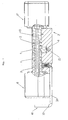
- the lock body 2 shown in Fig. 1 has the outer shape of a Profile cylinder. Approximately in the middle of the lock body 2 is located at the illustrated embodiment, a relation to the lock body rotatable closing element 4 with a cam 6 at its lower The End. In other embodiments, the closure element also be arranged asymmetrically in the lock body.
- the illustrated Lock element 2 has two, each for mounting a door knob suitable actuators 8, 8 'at its two opposite End up.
- the right actuating element 8 ' is non-rotatable with a shaft 18th connected.
- the shaft 18 is centered in a cylindrical cavity. 3 (see Fig. 1B) in the middle of the cylindrical upper portion of the Lock body 2 is arranged and rotatably mounted in the lock body 2.
- the left operating element 8 is suitable, for example, for mounting a door knob.
- a cylindrical Mounting portion 9 which is located inside the cylindrical cavity 3 is located inside the lock body 2 and in turn centrally one Passage space for the shaft 18 has. Through this passageway the shaft 18 extends through the entire attachment portion 9 into the actuating element 8.
- the mounting portion 9 is locked to the lock body 2 and inserted so far into the cavity 3 of the lock body 2, that he abuts the front side of an intermediate ring 7, which in turn is connected non-positively with the closing element 4.
- the cavity 3 is thus almost completely filled by the attachment portion 9.
- a bore 20 is formed, which for Attachment of the lock element in a door by means of a not shown Forend screw is used.
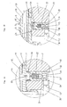
- FIG. 1A the mechanism for latching the operating member 8 shown enlarged in the cavity 3 of the lock body 2.
- the Fig. 1A and 1B respectively show the same section of the lock element 2.
- the latched state shown in FIG. 1 is shown in FIG. 1A shown, while in Fig. 1B, the actuator 8 only partially in the cavity 3 of the lock body 2 is inserted and not yet the locking element 10 is locked.
- Fig. 1A one can see the locking element 10, which in a Guide track 32 is guided in the interior of the lock body 2, and radially moved to the axis m of the cylindrical mounting portion 9 can be.
- the locking element 10 has a locking area 16, which is shown in more detail in FIG. 3.
- the locking area 16 is a bolt-like fastener 34 in held the locking element 10.
- the mounting portion 9 of the actuating element 8 has the outside a circumferential groove 24.
- the locking portion 16 of the locking element 9 sits in this groove 24, so that the actuator 8 while to the axis m is rotated, but not moved in the axial direction can.
- a spring 22 is in a circular cross-section recess 30 in Interior of the locking element 10 is arranged, wherein the cross section of the recess 30 substantially corresponds to the diameter of the spring 22.
- the recess 30 is open at the bottom; the spring 22 is with its lower End supported on a pin 14, which is perpendicular to the longitudinal center plane of the lock body 2 by the lower, elongated Area is plugged.
- the pin 14 is in a circular bore held the lock body 2, which has the same diameter as the Pin 14 has.
- the pin 14 extends through a slot 15 in Locking element 10, which is a radial displacement of the locking element 10th allows. By the interaction of slot 15 and pin 14 is the radial displacement of the locking element 10 up and down limited.
- the spring is relaxed and pushes the locking element 10 upwards and thus the locking element 16 in the groove 24. Der Pin 14 touches the upper end of the slot 15 in this position.
- the attachment portion 9 has shown in FIG. 1B at its in the Lock body 2 protruding end face 9 'a conical taper. 5 on.
- holes 12 and 28 can be made recognize which serve to release the explained locking.
- a Bore 12 in the lock body 2 and a bore 28 in the locking element 10th each have the same diameter d and both run parallel to the axis m of the cylindrical mounting portion 9.
- compressed Spring 22 (FIG. 1B) is the bore 12 in the lock body 2 and the Hole 28 in the locking element 10 aligned with each other and thus form a continuous cylindrical bore.
- an eccentric tool 40 may be used to release the locking.
- an eccentric tool 40 can be seen, which is inserted through the bore 12 and into the bore 28.
- the tool is shown alone.
- Such a tool consists of a handle 37 and a metal rod 36 with a round Cross-section, wherein the diameter of the rod 36 is approximately the Diameter d of the bores 12, 28 in the lock body 2 and in the locking element 10 must correspond.
- At the front end of the tool there is an eccentrically arranged smaller cylinder extension 38, whose diameter is at most the overlap of the two holes 12, 28 in the state of the lock member shown in Fig. 1A may.
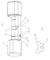
- Fig. 3 the lock element 2 according to the invention is shown in perspective. Through the downwardly open guide track 32 is the locking element 10 recognizable with the downwardly open recess 30 in its center. Above the pin 14 can be seen, which as a stop element serves and at the same time in Fig. 2 not visible spring 22 is supported. The locking portion 16 of the locking element 10 is in a slot-like Recess of the lock body 2 perpendicular to the longitudinal center plane.
- the locking portion 16 of the locking element 10 is increased shown.
- the locking area 16 is a flat one Metal part whose surface is substantially perpendicular to the axis m the cylindrical mounting portion 9 is located.
- the locking portion 16 has a bore 17 through which a Bolt for fixing the locking portion 16 in the locking element 10th can be plugged.
- the locking portion 16 of the locking element 10th is in a direction perpendicular to the longitudinal center plane of the lock element Direction narrower than the lower portion of the lock body. 2 Above this range, the locking portion 16 extends in said Direction sideways and then has a greater width than the lower section of the lock body 2.
- the Locking area 16 crescent-shaped, so that it to the annular groove 24 in the attachment portion 9 is complementary and not at the same time protrudes beyond the outer contour of the lock body 2.
- the invention relates to a lock element with a Lock body 2, one opposite the lock body 2 rotatable Closing element 4 and one projecting into the lock body 2 Cavity 3, in which one can be coupled with the closing element 4 and opposite the lock body 2 rotatable actuator 8 with a cylindrical mounting portion 9 is detachably fastened.
- the attachment section 9 of the actuating element 8 has on the outside a circumferential Groove 24, which can be latched with a locking element 10.
- the Locking element 10 is along a running within the lock body 2 Guided track 32 and radially to the axis m of the cylindrical Fixing portion 9 between two extreme positions displaced. With a spring 22, the locking element 10 in the direction of the groove 24 of the mounting portion 9 biased.
Landscapes
- Engineering & Computer Science (AREA)
- Mechanical Engineering (AREA)
- Lock And Its Accessories (AREA)
- Clamps And Clips (AREA)
- Chairs For Special Purposes, Such As Reclining Chairs (AREA)
- Portable Nailing Machines And Staplers (AREA)
- Snaps, Bayonet Connections, Set Pins, And Snap Rings (AREA)
Abstract
Description
Die Erfindung betrifft ein Schlosselement mit einem Schlosskörper, einem gegenüber dem Schlosskörper verdrehbaren Schließelement und einem mit dem Schließelement koppelbaren und gegenüber dem Schlosskörper verdrehbaren Betätigungselement.The invention relates to a lock element with a lock body, a against the lock body rotatable closing element and a can be coupled with the closing element and with respect to the lock body rotatable actuator.
Solche Schlosselemente kommen beispielsweise bei herkömmlichen Einsteckschlössern zum Einsatz, bei denen ein Profilzylinder als Schlosskörper und ein Türdrücker oder Türknauf als Betätigungselement dient. Beim Einbau derartiger Einsteckschlösser in eine Tür steht man vor der Aufgabe, die Betätigungselemente auf möglichst einfache, Platz sparende und optisch ansprechende Weise am Schlosskörper zu befestigen. Im Allgemeinen ist es nicht möglich, bereits vor der Montage des Schlosselements in der Tür beidseitig Betätigungselemente am Schlosskörper zu montieren, da die in der Tür vorgesehene Durchbrechung für das Schlosselement in der Regel kleiner ist, als die Betätigungselemente, so dass erst das z.B. mit einem Betätigungselement gekoppelte Schlosselement mit seiner diesem Betätigungselement abgewandten Seite voran durch die Durchbrechung gesteckt werden muss, bevor anschließend das andere Betätigungselement am Schlosskörper montiert werden kann. Zumindest auf einer Seite des Türschlosses muss also ein Betätigungselement nach dem Einbau des Schlosskörpers in die Tür nachträglich montiert werden. Insbesondere bei elektronischen Schließsystemen existiert dabei zusätzlich das Problem, dass in einem z.B. als Türknauf ausgebildeten Betätigungselement mechanische und elektronische Bauteile untergebracht werden müssen, so dass vergleichsweise wenig Platz für die Befestigung des Betätigungselements am Schlosskörper zur Verfügung steht.Such lock elements come for example in conventional mortise locks used in which a profile cylinder as a lock body and a door handle or doorknob serves as an actuator. At the Installation of such mortise locks in a door is the task the actuators on the simplest possible, space-saving and visually appealing way to attach to the lock body. In general it is not possible already before the assembly of the lock element in the door on both sides to mount actuators on the lock body, as provided in the door opening for the lock element in the rule is smaller than the actuators, so that only the e.g. with an actuating element coupled lock element with his this actuator facing away from the front through the opening must be plugged before then the other actuator can be mounted on the lock body. At least up one side of the door lock so an actuator after the Installation of the lock body in the door to be retrofitted. In particular, in electronic locking systems exists in addition the problem that in a e.g. designed as a door knob actuator housed mechanical and electronic components so that comparatively little space for attachment the actuating element is available on the lock body.
Eine gängige, aus dem Stand der Technik bekannte Lösung schlägt vor, zumindest eines der beiden Betätigungselemente auf eine sich durch das Türschloss erstreckende Welle aufzustecken und mit Hilfe eines radial auf die Welle einwirkenden Befestigungselements, z.B. eines Gewindestifts zu fixieren. Diese Lösung ist jedoch optisch nicht zufrieden stellend, da das Befestigungselement auf der Außenseite des Betätigungselements sichtbar ist. Zudem ist für eine ausreichend stabile Befestigung eine massive Welle erforderlich, was den für mechanische und elektronische Bauelemente zur Verfügung stehenden Bauraum begrenzt. Zudem sind Montage und Demontage eines auf diese Weise befestigbaren Betätigungselements relativ aufwändig.A common solution known from the prior art suggests at least one of the two actuators on one through the Door lock extending shaft to be plugged and with the help of a radially on the shaft-engaging fastener, e.g. to a threaded pin fix. However, this solution is not visually satisfactory because the Fastener visible on the outside of the actuator is. In addition, for a sufficiently stable attachment is a massive wave what is required for mechanical and electronic components for Limited available space. In addition, assembly and disassembly a fastened in this way actuator relative consuming.
Aufgabe der vorliegenden Erfindung ist daher, ein Schlosselement der eingangs genannten Art zur Verfügung zu stellen, an dem ein Betätigungselement auf einfache und platzsparende Weise lösbar befestigbar ist.Object of the present invention is therefore a lock element of initially provided type, in which an actuating element in a simple and space-saving manner is releasably fastened.
Diese Aufgabe wird erfindungsgemäß durch die Merkmale des Anspruchs
1 gelöst. Das Schlosselement weist dabei einen in den Schlosskörper
hineinragenden Hohlraum auf, in welchem das Betätigungselement mit
einem zylindrischen Befestigungsabschnitt lösbar befestigbar ist. Der
zylindrische Befestigungsabschnitt des Betätigungselements weist außenseitig
eine umlaufende Nut auf, die mit einem Rastelement verrastbar ist,
welches radial zu der Achse des zylindrischen Befestigungsabschnitts
verschiebbar im Schlosskörper geführt und mittels einer Feder in Richtung
der Nut des Betätigungselements beaufschlagt ist. Das Betätigungselement
wird also durch die Verrastung der Nut mit dem dazu korrespondierenden
Rastelement gegen axiales Verschieben gesichert. Insgesamt
geht auf Seiten des Betätigungselements praktisch kein Einbauraum für
die Befestigung verloren, so dass beispielsweise in einem Türknauf eines
elektronischen Türschlosses der gesamte Innenraum des Türknaufs für
mechanische und elektronische Bauteile zur Verfügung steht. Zudem sind
von außen bei der erfindungsgemäßen Konstruktion keinerlei Befestigungselemente
sichtbar, was hinsichtlich des Designs des Schlosses sehr
vorteilhaft ist.This object is achieved by the features of the
Vorteilhafte Ausführungsformen der Erfindung sind in der Beschreibung, den Figuren sowie den Unteransprüchen beschrieben.Advantageous embodiments of the invention are described in the description, the figures and the subclaims described.
Der zylindrische Befestigungsabschnitt kann an seinem in den Schlosskörper hineinragende Ende eine konische Verjüngung aufweisen, welche ein Verschieben des Rastelements gegen die Federspannung beim Einführen des Betätigungselements in den Hohlraum des Schlosskörpers ermöglicht. Wenn der Schlosskörper bereits in einem Türschloss montiert ist, kann das Betätigungselement somit auf einfache Weise am Schlosselement befestigt werden. Beim Einschieben des Betätigungselements mit seinem konisch verjüngten Befestigungsabschnitt in den Hohlraum des Schlosskörpers wird die beim Einschieben aufgewandte Kraft durch die schräge Fläche an dem konisch zulaufenden Befestigungsabschnitt in eine radial verlaufende Kraft, welche die Feder komprimieren kann, umgewandelt. Wenn das Betätigungselement weit genug in den Hohlraum eingesteckt ist, gelangt seine umlaufenden Nut mit dem Rastelement in Eingriff, wobei dieses dabei von der Feder in Richtung der Nut gedrückt wird. Das Betätigungselement kann also durch einfaches Aufstecken befestigt werden, ohne dass dazu ein Werkzeug nötig wäre, wobei zugleich Montagefehler zuverlässig vermieden werden. The cylindrical attachment portion may be at its in the lock body protruding end having a conical taper, which a displacement of the locking element against the spring tension during insertion of the actuating element in the cavity of the lock body allows. If the lock body is already mounted in a door lock, the actuator can thus easily on the lock element be attached. When inserting the actuator with its conically tapered attachment section into the cavity of the Lock body is the force applied during insertion through the inclined surface on the tapered attachment portion in a radially extending force, which can compress the spring converted. When the actuator is inserted far enough into the cavity is, its circumferential groove engages with the locking element, while this is pressed by the spring in the direction of the groove. The Actuator can therefore be attached by simply plugging, without the need for a tool, and at the same time assembly errors reliably avoided.
Nach einer vorteilhaften Ausführungsform der Erfindung kann das Rastelement entlang einer im Inneren des Schlosskörpers verlaufenden, insbesondere linearen Führungsbahn geführt sein, wobei seine Bewegung in zwei entgegengesetzten, radial zu der Achse des zylindrischen Befestigungsabschnitts verlaufenden Richtungen mittels Anschlagelementen begrenzt ist. Entlang der komplett außerhalb des Befestigungselements verlaufenden Führungsbahn ist das Rastelement somit bezogen auf den Innenraum des Befestigungselements Platz sparend untergebracht und mit Hilfe der Anschlagselemente wird der Weg, um den das Rastelement radial zu der Achse des zylindrischen Befestigungsabschnitts verschiebbar ist, begrenzt. In der einen Extremposition des Rastelementes ist der Befestigungsabschnitt des Betätigungselements mit dem Rastelement verrastet, in der entgegengesetzten Extremposition ist das Rastelement von der Nut des Befestigungsabschnitts beabstandet, so dass zwischen Rastelement und Nut kein Eingriff existiert, wodurch das Betätigungselement mit seinem zylindrischen Befestigungsabschnitt im Schlosskörper axial verschoben werden kann.According to an advantageous embodiment of the invention, the locking element along a running inside the lock body, in particular be guided linear guideway, with its movement in two opposite, radially to the axis of the cylindrical mounting portion extending directions by means of stop elements is limited. Along the completely outside the fastener extending guideway is the locking element thus based on the Interior of the fastener space-saving housed and with the help of the stop elements is the way to the locking element displaceable radially to the axis of the cylindrical mounting portion is limited. In an extreme position of the locking element is the attachment portion locked the actuating element with the locking element, in the opposite extreme position, the locking element of the groove the fastening portion spaced so that between the locking element and groove no interference exists, whereby the actuator with his cylindrical attachment portion axially displaced in the lock body can be.
Als Anschlagelemente können beispielsweise ein im Rastelement vorgesehenes Langloch und ein im Schlosskörper vorgesehener Stift, welcher sich durch das Langloch erstreckt, dienen. Je größer die Längserstreckung des Langlochs im Vergleich zum Durchmesser des genannten Stifts ist, desto größer wird die Strecke, um die das Rastelement in radialer Richtung verschoben werden kann. Eine derartige Konstruktion ist einfach realisierbar und zudem dauerhaft und wartungsfrei.As stop elements, for example, a provided in the locking element Slot and a provided in the lock body pin, which itself extends through the slot, serve. The greater the longitudinal extent of the Long hole compared to the diameter of the said pen is the more becomes larger the distance to which the locking element in the radial direction can be moved. Such a construction is easy to implement and also durable and maintenance-free.
Nach einer bevorzugten Ausführungsform der Erfindung kann die Feder, welche das Rastelement in Richtung der Nut des Befestigungsabschnitts beaufschlagt, in einer sich radial zur Achse des zylindrischen Befestigungsabschnittes erstreckenden Aussparung des Rastelements angeordnet sein. Der vorstehend bereits erwähnte Stift, welcher als Anschlagselement dient, kann mit einem sich in diese Aussparung hineinerstreckenden Bereich ein Abstützelement für die Feder bilden. Die Aussparung, in der die Feder angeordnet ist, kann an der Oberfläche des Schlosskörpers offen sein, genauso ist aber auch eine kammerartige geschlossene Aussparung denkbar.According to a preferred embodiment of the invention, the spring, which the locking element in the direction of the groove of the mounting portion acted upon, in a radially to the axis of the cylindrical attachment portion extending recess of the locking element arranged be. The previously mentioned pin, which as a stop element serves, can with a hineinerstreckenden in this recess Area form a support element for the spring. The recess, in the spring is arranged on the surface of the lock body be open, as well as a chamber-like closed recess conceivable.
Nach einer weiteren bevorzugten Ausführungsform der Erfindung weisen sowohl das Rastelement als auch der Schlosskörper jeweils eine Bohrung auf, wobei die beiden Bohrungen zumindest im Wesentlichen den gleichen Durchmesser haben und parallel zur Achse des zylindrischen Befestigungsabschnittes verlaufen. Die beiden Bohrungen sind dabei so angeordnet, dass die schlosskörperseitige Bohrung sich von dem Ende des Schlosskörpers, an dem das Betätigungselement befestigbar ist, bis zu der Bohrung des im Schlosskörper gelagerten Rastelements erstreckt, und dass die beiden Bohrungen bei komprimierter Feder miteinander ausgerichtet sind und sich bei entspannter Feder bereichsweise überlappen. Bei komprimierter Feder liegen die beiden Bohrungen also axial hintereinander. Eine derartige Anordnung ermöglicht ein Lösen der Verrastung des Rastelements mit dem Betätigungselement mit Hilfe eines speziellen Exzenterwerkzeugs. Ein solches Werkzeug ähnelt einem Schraubendreher mit einem Griff und einem daran befestigten runden Metallstab. Die Spitze dieses Metallstabes bildet ein zylindrischer Fortsatz, dessen Querschnitt kleiner als der des Metallstabes ist, und der am stirnseitigen Ende des Metallstabs exzentrisch an diesem angeordnet ist. Bei entspannter Feder überlappen sich die beiden Bohrungen nur bereichsweise und ein Exzenterwerkzeug kann mit seinem zylindrischen Fortsatz durch die schlosskörperseitige Bohrung in den Überlappungsbereich der im Rastelement vorgesehenen Bohrung eingeführt werden. Wenn das Exzenterwerkzeug nun gedreht wird, wird das Rastelement von der Nut des Befestigungsabschnitts weggezogen und die Feder komprimiert. Die beiden Bohrungen werden miteinander ausgerichtet und die Verrastung des Rastelements mit dem Betätigungselement wird gelöst.According to another preferred embodiment of the invention both the locking element and the lock body each have a bore on, wherein the two holes at least substantially the same Have diameter and parallel to the axis of the cylindrical mounting portion run. The two holes are arranged in such a way that the lock body side bore extends from the end of the Lock body to which the actuator is fastened, up to the Bore of the lock body mounted in the locking element extends, and that the two holes aligned with each other when compressed spring are and overlap partially with relaxed spring. at compressed spring so the two holes are axially behind each other. Such an arrangement allows a release of the latching of the Locking element with the actuating element by means of a special eccentric tool. Such a tool resembles a screwdriver with a handle and a round metal rod attached to it. The summit this metal rod forms a cylindrical extension whose cross-section smaller than that of the metal rod, and the front end of the Metal rod is arranged eccentrically on this. With relaxed spring The two holes overlap only partially and an eccentric tool can with its cylindrical extension through the lock body side Bore in the overlap area of the locking element be provided for drilling. If the eccentric tool is now rotated, the locking element of the groove of the mounting portion pulled away and compressed the spring. The two holes are aligned with each other and the locking of the locking element with the actuator is released.
Der Durchmesser der beiden parallel zur Achse des zylindrischen Befestigungsabschnitts verlaufenden Bohrungen kann jeweils zwischen 2 mm und 5 mm, insbesondere etwa 3 mm betragen. Bei entspannter Feder überlappen sich die beiden Bohrungen vorzugsweise etwa um die Hälfte ihres Durchmessers. Auf diese Weise wird bei einer sinnvollen Eingrifftiefe zwischen Rastelement und Nut eine optimale Kraftübertragung beim Ansetzen eines Exzenterwerkzeugs zum Lösen der Verrastung erzielt.The diameter of the two parallel to the axis of the cylindrical attachment portion extending holes can each be between 2 mm and 5 mm, in particular about 3 mm. With relaxed spring The two bores preferably overlap by about half their diameter. In this way, at a reasonable engagement depth between locking element and groove optimum power transmission Attachment of an eccentric tool for releasing the locking achieved.
Das Betätigungselement ist auf die erläuterte Weise relativ einfach vom Schlosskörper lösbar, trotzdem bietet die Tatsache, dass zum Lösen der Verrastung ein spezielles Werkzeug nötig ist, einen gewissen Schutz gegen ein missbräuchliches Entfernen des Betätigungselements. Von besonderem Vorteil ist dabei, dass das Betätigungselement beliebig oft montiert und demontiert werden kann, ohne dass das Schlosselement dabei beschädigt wird bzw. ohne dass Verschleißerscheinungen auftreten.The actuator is in the manner explained relatively simple from Lock body solvable, nevertheless offers the fact that to solve the Locking a special tool is needed, some protection against an abusive removal of the actuator. Of special The advantage here is that the actuator mounted as often as desired and can be dismantled without damaging the lock element is or without signs of wear occur.
Das erfindungsgemäße Schlosselement kann eine mittig im Hohlraum des Schlosskörpers drehbar gelagerte Welle aufweisen, welche an einem Ende drehfest mit einem zweiten Betätigungselement verbunden ist, wohingegen das erste Betätigungselement eine Aufnahme für das andere Ende der Welle besitzt. Mit Hilfe zusätzlicher Koppelelemente ist es aufgrund der vorhandenen Welle möglich, eine kraftschlüssige Verbindung zwischen den beiden Betätigungselementen herzustellen. Da die Welle erfindungsgemäß nicht zur Fixierung des ersten Betätigungselements verwendet wird, kann sie auch als Hohlwelle ausgebildet sein, wodurch zusätzlicher Platz für elektronische Bauteile, Kabel oder ähnliches zur Verfügung steht. The lock element according to the invention can be located centrally in the cavity of the Lock body having rotatably mounted shaft, which at one end rotatably connected to a second actuator, whereas the first actuator a receptacle for the other end of the Wave owns. With the help of additional coupling elements, it is due to the existing shaft possible, a non-positive connection between to produce the two actuators. Since the shaft according to the invention not used to fix the first actuator is, it can also be designed as a hollow shaft, whereby additional Space for electronic components, cables or the like is available.
Der Befestigungsabschnitt kann an seinem in den Hohlraum des Schlosskörpers hineinragenden Ende stirnseitig ein erstes Kraftübertragungselement aufweisen, welches mit einem dazu korrespondierenden zweiten Kraftübertragungselement in Eingriff bringbar ist, welches seinerseits drehfest mit dem Schließelement gekoppelt ist. Auf diese Weise kann eine kraftschlüssige Verbindung zwischen dem lösbar befestigten Befestigungsabschnitt und dem Schließelement hergestellt werden, so dass sich das Schließelement bei Betätigung des Betätigungselements dreht. Als Kraftübertragungselemente sind beispielsweise eine radial verlaufende Nut und zumindest ein dazu korrespondierender Vorsprung möglich.The attachment portion may be at its in the cavity of the lock body protruding end frontally a first power transmission element have, which with a corresponding thereto second Power transmission element can be brought into engagement, which in turn rotatably coupled to the closing element. This way a can non-positive connection between the releasably secured mounting portion and the closure member are made so that the closing element rotates upon actuation of the actuating element. When Power transmission elements are, for example, a radially extending groove and at least one corresponding projection possible.
Der Schlosskörper kann beispielsweise die Form eines handelsüblichen, genormten Profilzylinders haben. Ein solcher Schlosskörper kann, ohne dass zusätzliche Adapter notwendig sind, in üblichen Türschlössern mit genormten Abmessungen verwendet werden.The lock body may, for example, take the form of a commercial, standardized profile cylinder have. Such a lock body can, without that additional adapters are necessary in common door locks with standardized dimensions are used.
Ein derart geformter Schlosskörper besteht aus einem oberen Abschnitt mit zylindrischem Querschnitt und einem unteren Abschnitt mit einem lang gestreckten Querschnitt. Der im unteren Abschnitt des Schlosskörpers geführte Bereich des Rastelements muss in einer senkrecht zur Längsmittelebene des Schlosselements verlaufenden Richtung schmaler als der untere Abschnitt des Schlosskörpers sein. Um eine bessere Kraftübertragung zwischen dem Rastelement und dem Befestigungsabschnitt zu erreichen, kann das Rastelement an seinem oberen Ende einen in die umlaufende Nut des Befestigungsabschnitts passenden Verriegelungsbereich aufweisen, welcher in einer senkrecht zur Längsmittelebene des Schlosselements verlaufenden Richtung eine größere Bereite als der untere Abschnitt des Profilzylinders besitzt. Derjenige Bereich der Nut, mit dem sie mit dem Rastelement in Eingriff steht, wird auf diese Weise vergrößert, wodurch ein besserer Halt erzielbar ist.Such a molded lock body consists of an upper portion with a cylindrical cross section and a lower section with a elongated cross-section. The one in the lower section of the lock body guided area of the locking element must be in a perpendicular to Narrower longitudinal direction of the lock element extending direction be as the lower portion of the lock body. To get a better power transmission between the locking element and the attachment portion To reach, the locking element at its upper end in the circumferential groove of the mounting section mating locking area which, in a direction perpendicular to the longitudinal center plane of the Castle element extending direction a greater ready than the lower Section of the profile cylinder has. The area of the groove, with which it engages with the detent element is enlarged in this way, whereby a better grip is achievable.
Im Folgenden wird die Erfindung anhand eines bevorzugten Ausführungsbeispiels und unter Bezugnahme auf die beigefügten Zeichnungen näher beschrieben. Dabei zeigen:
- Fig. 1
- einen Schnitt durch die Längsmittelebene eines erfindungsgemäßen Schlosselements, wobei das Rastelement mit dem Betätigungselement verrastet ist, mit einem in das Schlosselement eingeführten Exzenterwerkzeug;
- Fig. 1A
- einen vergrößerten, das Rastelement und die Spitze des Exzenterwerkzeugs umfassenden Ausschnitt aus der Fig. 1;
- Fig. 1B
- den gleichen Ausschnitt wie die Fig. 1A, wobei im Gegensatz zur Fig. 1A das Rastelement nicht mit dem Betätigungselement verrastet und der Befestigungsabschnitt des Betätigungselements nicht vollständig in den schlosskörperseitigen Hohlraum eingeschoben ist;
- Fig. 2
- einen Längsschnitt durch ein Exzenterwerkzeug zum Lösen der Verrastung des Rastelements mit dem Betätigungselement;
- Fig. 2A
- einen vergrößerten, die Spitze des Exzenterwerkzeugs umfassenden Ausschnitt aus Fig. 2;
- Fig. 3
- eine perspektivische Ansicht des erfindungsgemäßen Schlosselements mit zur Montage eines Türknaufs geeigneten Betätigungselementen, und
- Fig. 4
- eine Ansicht eines erfindungsgemäßen Verriegelungsabschnitt des Rastelements mit senkrecht zur Längsmittelebene des Schlosselements verlaufender Blickrichtung.
- Fig. 1
- a section through the longitudinal center plane of a lock element according to the invention, wherein the locking element is latched to the actuating element, with an inserted into the lock element eccentric tool;
- Fig. 1A
- an enlarged, the locking element and the tip of the eccentric comprehensive cutout of Fig. 1;
- Fig. 1B
- the same section as Fig. 1A, wherein in contrast to Figure 1A, the locking element is not locked to the actuating element and the mounting portion of the actuating element is not fully inserted into the lock body side cavity.
- Fig. 2
- a longitudinal section through an eccentric tool for releasing the locking of the locking element with the actuating element;
- Fig. 2A
- an enlarged, the tip of the eccentric comprehensive cutout of Fig. 2;
- Fig. 3
- a perspective view of the lock element according to the invention with suitable for mounting a door knob actuators, and
- Fig. 4
- a view of a locking portion of the locking element according to the invention with perpendicular to the longitudinal center plane of the lock element extending viewing direction.
Der in Fig. 1 dargestellten Schlosskörper 2 besitzt die äußere Form eines
Profilzylinders. Etwa in der Mitte des Schlosskörpers 2 befindet sich bei
dem dargestellten Ausführungsbeispiel ein gegenüber dem Schlosskörper
verdrehbares Schließelement 4 mit einem Schließbart 6 an seinem unteren
Ende. Bei anderen Ausführungsbeispielen kann das Schließelement
auch asymmetrisch im Schlosskörper angeordnet sein. Das dargestellte
Schlosselement 2 besitzt zwei, jeweils für die Montage eines Türknaufs
geeignete Betätigungselemente 8, 8' an seinen beiden entgegengesetzten
Enden. Das rechte Betätigungselement 8' ist drehfest mit einer Welle 18
verbunden. Die Welle 18 ist mittig in einem zylinderförmigen Hohlraum 3
(siehe Fig. 1B) in der Mitte des zylinderförmigen oberen Bereichs des
Schlosskörpers 2 angeordnet und drehbar im Schlosskörper 2 gelagert.
Sie weist ihrerseits wiederum einen zylindrischen, sich über die gesamte
Länge der Welle 18 erstreckenden Hohlraum 19 auf, durch welchen beispielsweise
Kabel geführt werden können. Das linke Betätigungselement 8
ist beispielsweise zum Montieren eines Türknaufes geeignet. An seiner
dem Schlosskörper 2 zugewandten Seite besitzt es einen zylindrische
Befestigungsabschnitt 9, der sich innerhalb des zylindrischen Hohlraums
3 im Inneren des Schlosskörpers 2 befindet und seinerseits mittig einen
Durchtrittsraum für die Welle 18 aufweist. Durch diesen Durchtrittsraum
erstreckt sich die Welle 18 durch den gesamten Befestigungsabschnitt 9
bis in das Betätigungselement 8.The
In Fig. 1 ist der Befestigungsabschnitt 9 mit dem Schlosskörper 2 verrastet
und so weit in den Hohlraum 3 des Schlosskörpers 2 eingeschoben,
dass er stirnseitig an einen Zwischenring 7 anstößt, welches seinerseits
mit dem Schließelement 4 kraftschlüssig verbunden ist. Der Hohlraum 3
ist somit durch den Befestigungsabschnitt 9 fast völlig ausgefüllt.In Fig. 1, the mounting portion 9 is locked to the
Im unteren lang gestreckten Abschnitt des Schlosskörpers 2 ist senkrecht
zu dessen Längsmittelebene eine Bohrung 20 ausgebildet, welche zur
Befestigung des Schlosselements in einer Tür mittels einer nicht dargestellten
Stulpschraube dient.In the lower elongated portion of the
In Fig. 1A ist der Mechanismus zum Verrasten des Betätigungselements 8
in dem Hohlraum 3 des Schlosskörpers 2 vergrößert dargestellt. Die Fig.
1A und 1B zeigen dabei jeweils den gleichen Ausschnitt des Schlosselements
2. Der in der Fig. 1 dargestellte verrastete Zustand ist in der Fig. 1A
gezeigt, während in der Fig. 1B das Betätigungselement 8 nur teilweise in
den Hohlraum 3 des Schlosskörpers 2 eingeschoben und noch nicht mit
dem Rastelement 10 verrastet ist.In Fig. 1A, the mechanism for latching the operating
In Fig. 1A kann man das Rastelement 10 erkennen, welches in einer
Führungsbahn 32 im Innern des Schlosskörpers 2 geführt ist, und radial
zur Achse m des zylindrischen Befestigungsabschnitts 9 verschoben
werden kann. An seiner Oberseite weist das Rastelement 10 einen Verriegelungsbereich
16 auf, welcher genauer in Fig. 3 gezeigt ist. Der Verriegelungsbereich
16 wird von einem bolzenartigen Befestigungselement 34 in
dem Rastelement 10 gehalten. In Fig. 1A, one can see the locking
Der Befestigungsabschnitt 9 des Betätigungselements 8 weist außenseitig
eine umlaufende Nut 24 auf. Der Verriegelungsabschnitt 16 des Rastelements
9 sitzt in dieser Nut 24, so dass das Betätigungselement 8 zwar um
die Achse m gedreht, aber nicht in axialer Richtung verschoben werden
kann.The mounting portion 9 of the
Eine Feder 22 ist in einer im Querschnitt runden Aussparung 30 im
Innern des Rastelements 10 angeordnet, wobei der Querschnitt der Aussparung
30 im Wesentlichen dem Durchmesser der Feder 22 entspricht.
Die Aussparung 30 ist nach unten offen; die Feder 22 ist mit ihrem unteren
Ende an einem Stift 14 abgestützt, welcher senkrecht zur Längsmittelebene
des Schlosskörpers 2 durch dessen unteren, lang gestreckten
Bereich gesteckt ist. Der Stift 14 ist dabei in einer kreisförmigen Bohrung
des Schlosskörpers 2 gehalten, welche den gleichen Durchmesser wie der
Stift 14 besitzt. Gleichzeitig verläuft der Stift 14 durch ein Langloch 15 im
Rastelement 10, welches ein radiales Verschieben des Rastelements 10
ermöglicht. Durch das Zusammenwirken von Langloch 15 und Stift 14 ist
die radiale Verschiebbarkeit des Rastelements 10 nach oben und unten
begrenzt. In Fig. 1A ist die Feder entspannt und drückt das Rastelement
10 nach oben und somit das Verriegelungselement 16 in die Nut 24. Der
Stift 14 berührt in dieser Position das obere Ende des Langlochs 15.A
In Fig. 1B ist der zylindrische Befestigungsabschnitt 9 des Betätigungselements
8 nicht vollständig in den Hohlraum 3 des Schlosskörpers 2
eingeführt.In Fig. 1B, the cylindrical mounting portion 9 of the
Der Befestigungsabschnitt 9 weist gemäß Fig. 1B an seiner in den
Schlosskörper 2 hineinragenden Stirnseite 9' eine konische Verjüngung 5
auf. Beim Einführen des Betätigungselements 8 mit seinem Befestigungsabschnitt
9 in den Hohlraum 3 wird durch die angeschrägte Fläche an der
Vorderseite des Befestigungsabschnitts 9 das Rastelement 10 nach unten
gedrückt und die Feder 22 somit komprimiert, wie in Fig. 1B gezeigt.
Wenn das Betätigungselement 8 bis zum Anschlag in den Hohlraum 3
eingeführt wird, gerät das Rastelement 10 mit seinem Verriegelungsabschnitt
16 mit der Nut 24 in Eingriff. Die Feder 22 entspannt sich und das
Betätigungselement ist wie in Fig. 1A dargestellt mit dem Schlosskörper
verrastet.The attachment portion 9 has shown in FIG. 1B at its in the
Des Weiteren kann man in den Fig. 1A und 1B Bohrungen 12 und 28
erkennen, welche zum Lösen der erläuterten Verrastung dienen. Eine
Bohrung 12 im Schlosskörper 2 und eine Bohrung 28 im Rastelement 10
haben jeweils den gleichen Durchmesser d und verlaufen beide parallel
zur Achse m des zylindrischen Befestigungsabschnitts 9. Bei komprimierter
Feder 22 (Fig. 1B) sind die Bohrung 12 im Schlosskörper 2 und die
Bohrung 28 im Rastelement 10 miteinander ausgerichtet und bilden somit
eine durchgehende zylindrische Bohrung. Wenn das Rastelement 10 mit
dem Betätigungselement 8 verrastet ist, d.h. wenn die Feder wie in Fig. 1A
gezeigt entspannt ist, sind die beiden Bohrungen 12, 28 gegeneinander
versetzt und überlappen sich etwa um die Hälfte ihres Durchmessers d.Furthermore, in FIGS. 1A and 1B, holes 12 and 28 can be made
recognize which serve to release the explained locking. A
Zum Lösen der Verrastung kann ein Exzenterwerkzeug 40 verwendet
werden. In den Fig. 1, 1A und 1B ist ein Exzenterwerkzeug 40 zu erkennen,
welches durch die Bohrung 12 und in die Bohrung 28 gesteckt ist. In
den Fig. 2 und 2A ist das Werkzeug alleine dargestellt. Ein solches Werkzeug
besteht aus einem Griff 37 und einem Metallstab 36 mit einem runden
Querschnitt, wobei der Durchmesser des Stabes 36 in etwa dem
Durchmesser d der Bohrungen 12, 28 im Schlosskörper 2 bzw. im Rastelement
10 entsprechen muss. Am stirnseitigen Ende des Werkzeugs
befindet sich ein exzentrisch angeordneter kleinerer Zylinderfortsatz 38,
dessen Durchmesser maximal der Überlappung der beiden Bohrungen 12,
28 in dem in Fig. 1A dargestellten Zustand des Schlosselements entsprechen
darf. Durch die Bohrung 12 im Schlosskörper hindurch kann das
Exzenterwerkzeug 40 bei entspannter Feder 22 mit seinem Zylinderfortsatz
38 in die Bohrung 28 im Rastelement 10 eingeführt werden (Fig. 1A).
Wenn das Werkzeug nun gedreht wird, wird das Rastelement 10 durch
den Zylinderfortsatz 40 nach unten gezogen und die Verbindung zwischen
dem Betätigungselement 8 und dem Schlosskörper 2 somit gelöst, so dass
das Betätigungselement 8 aus dem Hohlraum 3 im Schlosskörper 2
heraus gezogen werden kann (Fig. 1B).To release the locking an
In Fig. 3 ist das erfindungsgemäße Schlosselement 2 perspektivisch dargestellt.
Durch die nach unten offene Führungsbahn 32 ist das Rastelement
10 mit der nach unten offenen Aussparung 30 in seiner Mitte erkennbar.
Oberhalb ist der Stift 14 zu erkennen, welcher als Anschlagelement
dient und gleichzeitig die in Fig. 2 nicht sichtbare Feder 22 abstützt.
Der Verriegelungsbereich 16 des Rastelements 10 liegt in einer schlitzartigen
Aussparung des Schlosskörpers 2 senkrecht zu dessen Längsmittelebene.In Fig. 3, the
In Fig. 4 ist der Verriegelungsbereich 16 des Rastelements 10 vergrößert
dargestellt. Bei dem Verriegelungsbereich 16 handelt es sich um ein flaches
Metallteil, dessen Oberfläche im Wesentlichen senkrecht zur Achse m
des zylindrischen Befestigungsabschnitts 9 liegt. An seinem unteren Ende
besitzt der Verriegelungsbereich 16 eine Bohrung 17, durch welche ein
Bolzen zum Fixieren des Verriegelungsbereichs 16 im Rastelement 10
gesteckt werden kann. Der Verriegelungsbereich 16 des Rastelements 10
ist in einer senkrecht zur Längsmittelebene des Schlosselements verlaufenden
Richtung schmaler als der untere Abschnitt des Schlosskörpers 2.
Oberhalb dieses Bereichs dehnt sich der Verriegelungsbereich 16 in besagter
Richtung seitlich aus und besitzt dann eine größere Breite als der
untere Abschnitt des Schlosskörpers 2. An seinem oberen Ende ist der
Verriegelungsbereich 16 sichelförmig, so dass er zu der ringförmigen Nut
24 im Befestigungsabschnitt 9 komplementär ist und gleichzeitig nicht
über die Außenkontur des Schlosskörpers 2 hinausragt.In Fig. 4, the locking
Zusammengefasst betrifft die Erfindung ein Schlosselement mit einem
Schlosskörper 2, einem gegenüber dem Schlosskörper 2 verdrehbaren
Schließelement 4 und einem in den Schlosskörper 2 hineinragenden
Hohlraum 3, in dem ein mit dem Schließelement 4 koppelbares und gegenüber
dem Schlosskörper 2 drehbares Betätigungselement 8 mit einem
zylindrischen Befestigungsabschnitt 9 lösbar befestigbar ist. Der Befestigungsabschnitt
9 des Betätigungselements 8 weist außenseitig eine umlaufende
Nut 24 auf, welche mit einem Rastelement 10 verrastbar ist. Das
Rastelement 10 ist entlang einer innerhalb des Schlosskörpers 2 verlaufenden
Führungsbahn 32 geführt und radial zu der Achse m des zylindrischen
Befestigungsabschnitts 9 zwischen zwei Extrempositionen verschiebbar.
Mit einer Feder 22 ist das Rastelement 10 in Richtung der Nut
24 des Befestigungsabschnitts 9 vorgespannt. In summary, the invention relates to a lock element with a
- 22
- Schlosskörperlock body
- 33
- zylindrischer Hohlraumcylindrical cavity
- 44
- Schließelementclosing element
- 55
- konische Verjüngungconical rejuvenation
- 66
- SchließbartCam
- 77
- Zwischenringintermediate ring
- 88th
- Betätigungselementactuator
- 8'8th'
- Betätigungselementactuator
- 99
- zylindrischer Befestigungsabschnittcylindrical attachment section
- 9'9 '
- Stirnseite des zylindrischen BefestigungsabschnittsEnd face of the cylindrical attachment portion
- 1010
- Rastelementlocking element
- 1212
- Bohrungdrilling
- 1414
- Stiftpen
- 1515
- LanglochLong hole
- 1616
- Verriegelungsbereichlocking area
- 1717
- Bohrung im VerriegelungsbereichBore in the locking area
- 1818
- Wellewave
- 1919
- Hohlraumcavity
- 2020
- Montagebohrungmounting hole
- 2222
- Federfeather
- 2424
- Nutgroove
- 2828
- Bohrungdrilling
- 3030
- Aussparungrecess
- 3232
- Führungsbahnguideway
- 3434
- Befestigungselementfastener
- 3636
- Metallstabmetal rod
- 3737
- GriffHandle
- 3838
- ZylinderfortsatzCylindrical extension
- 4040
- ExzenterwerkzeugExzenterwerkzeug
- dd
-
Durchmesser der Bohrungen 12 und 28Diameter of the
holes - mm
- Achse des zylindrischen Befestigungsabschnitts 9Axis of the cylindrical attachment portion 9
Claims (11)
dadurch gekennzeichnet, dass der Befestigungsabschnitt (9) an seinem in den Schlosskörper hineinragenden Ende eine konische Verjüngung (5) aufweist, welche ein Verschieben des Rastelements (10) gegen die Federspannung beim Einführen des Betätigungselements (8) in den Hohlraum (3) des Schlosskörpers (2) ermöglicht.Lock element according to claim 1,
characterized in that the fastening portion (9) at its end projecting into the lock body has a conical taper (5), which is a displacement of the locking element (10) against the spring tension during insertion of the actuating element (8) into the cavity (3) of the lock body (2).
dadurch gekennzeichnet, dass das Rastelement (10) entlang einer innerhalb des Schlosskörpers (2) verlaufenden Führungsbahn (32) geführt ist, wobei seine Bewegung in zwei entgegengesetzten, radial zu der Achse (m) des zylindrischen Befestigungsabschnitts (9) verlaufenden Richtungen mittels Anschlagelementen (14, 15) begrenzt ist.Lock element according to claim 1 or 2,
characterized in that the latching element (10) is guided along a guideway (32) extending inside the lock body (2), its movement being effected in two opposite directions, radially extending to the axis (m) of the cylindrical mounting section (9), by means of stop elements (Fig. 14, 15) is limited.
dadurch gekennzeichnet, dass die Anschlagelemente (14, 15) mittels eines im Rastelement (10) vorgesehenen Langlochs (15) und eines schlosskörperseitig vorgesehenen, sich durch das Langloch (15) erstreckenden Stifts (14) realisiert sind.Lock element according to claim 3,
characterized in that the stop elements (14, 15) by means of a latching element (10) provided in the slot (15) and a lock body side provided, through the slot (15) extending pin (14) are realized.
dadurch gekennzeichnet, dass die Feder (22) in einer sich radial zur Achse (m) des zylindrischen Befestigungsabschnittes (9) erstreckenden Aussparung (30) des Rastelements (10) angeordnet ist, wobei der Stift (14) mit seinem, sich in diese Aussparung (30) hinein erstreckenden Bereich ein Abstützelement für die Feder (22) bildet.Lock element according to claim 4,
characterized in that the spring (22) in a radially to the axis (m) of the cylindrical mounting portion (9) extending recess (30) of the locking element (10) is arranged, wherein the pin (14) with his, in this recess (30) extending portion forms a support element for the spring (22).
dadurch gekennzeichnet, dass das Rastelement (10) und der Schlosskörper (2) jeweils eine Bohrung (12, 28) aufweisen, wobei beide Bohrungen (12, 28) zumindest im wesentlichen den gleichen Durchmesser (d) haben und parallel zur Achse (m) des zylindrischen Befestigungsabschnitts (9) verlaufen,
dass die schlosskörperseitige Bohrung (12) sich von dem Ende des Schlossköpers (2), an dem das Betätigungselement (8)befestigbar ist, bis zu dem im Schlosskörper (2) gelagerten Rastelement (10) erstreckt, und
dass die beiden Bohrungen (12, 28) bei komprimierter Feder (22) miteinander ausgerichtet sind und sich bei entspannter Feder (22) bereichsweise überlappen.Lock element according to one of the preceding claims,
characterized in that the latching element (10) and the lock body (2) each have a bore (12, 28), both bores (12, 28) at least substantially the same diameter (d) and parallel to the axis (m) of the cylindrical attachment portion (9) extend,
in that the lock body-side bore (12) extends from the end of the lock body (2), on which the actuating element (8) can be fastened, to the latching element (10) mounted in the lock body (2), and
that the two bores (12, 28) are aligned with each other with compressed spring (22) and overlap in regions with relaxed spring (22).
dadurch gekennzeichnet, dass der Durchmesser (d) der beiden parallel zur Achse (m) des zylindrischen Befestigungsabschnitts (9) verlaufenden Bohrungen (12, 28) im Rastelement (10) und im Schlosskörper (2) jeweils zwischen 2 mm und 5 mm, insbesondere etwa 3mm beträgt und sich die beiden Bohrungen (12, 28) bei entspannter Feder (22) etwa um die Hälfte ihres Durchmessers (d) überlappen.Lock element according to claim 6,
characterized in that the diameter (d) of the two parallel to the axis (m) of the cylindrical fixing portion (9) extending bores (12, 28) in the locking element (10) and in the lock body (2) in each case between 2 mm and 5 mm, in particular is about 3mm and the two holes (12, 28) with relaxed spring (22) about half of their diameter (d) overlap.
dadurch gekennzeichnet, dass es eine mittig im Hohlraum (3) des Schlosskörpers (2) drehbar gelagerte Welle (18) aufweist, welche an einem Ende drehfest mit einem zweiten Betätigungselement (8') verbunden ist, wohingegen das erste Betätigungselement (8) eine Aufnahme für das andere Ende der Welle (18) besitzt.Lock element according to one of the preceding claims,
characterized in that it has a center in the cavity (3) of the lock body (2) rotatably mounted shaft (18) which is rotatably connected at one end with a second actuating element (8 '), whereas the first actuating element (8) has a receptacle for the other end of the shaft (18) has.
dadurch gekennzeichnet, dass der Befestigungsabschnitt (9) an seinem in den Hohlraum (3) hineinragenden Ende stirnseitig ein Kraftübertragungselement aufweist, welches mit einem dazu korrespondierenden zweiten Kraftübertragungselement in Eingriff bringbar ist, das drehfest mit dem Schließelement (4) gekoppelt ist.Lock element according to one of the preceding claims,
characterized in that the fastening portion (9) at its end projecting into the cavity (3) end face a force transmission element, which is engageable with a corresponding thereto second power transmission element which is non-rotatably coupled to the closing element (4).
dadurch gekennzeichnet, dass der Schlosskörper (2) die Form eines Profilzylinders hat.Lock element according to one of the preceding claims,
characterized in that the lock body (2) has the shape of a profile cylinder.
wobei der Profilzylinder aus einem oberen Abschnitt mit zylindrischem Querschnitt und einem unteren Abschnitt mit einem lang gestreckten Querschnitt besteht,
dadurch gekennzeichnet, dass der im unteren Abschnitt des Profilzylinders geführte Bereich des Rastelements (10) in einer senkrecht zur Längsmittelebene des Schlosselements (2) verlaufenden Richtung schmaler als der untere Abschnitt des Profilzylinders ist, und
dass das Rastelement (10) oberhalb dieses Bereichs einen in die umlaufende Nut (24) des Befestigungsabschnitts (9) passenden Verriegelungsbereich (16) aufweist, welcher in der genannten Richtung eine größere Breite als der untere Abschnitt des Profilzylinders besitzt.Lock element according to claim 10,
wherein the profile cylinder consists of an upper section with a cylindrical cross section and a lower section with an elongated cross section,
characterized in that the guided in the lower portion of the profile cylinder portion of the locking element (10) in a direction perpendicular to the longitudinal center plane of the lock element (2) extending direction is narrower than the lower portion of the profile cylinder, and
that the latching element (10) has a fitting into the circumferential groove (24) of the fastening section (9) locking portion (16) above this region which has a greater width than the lower section of the profile cylinder in the named direction.
Applications Claiming Priority (2)
| Application Number | Priority Date | Filing Date | Title |
|---|---|---|---|
| DE102004011449 | 2004-03-09 | ||
| DE102004011449A DE102004011449A1 (en) | 2004-03-09 | 2004-03-09 | lock element |
Publications (2)
| Publication Number | Publication Date |
|---|---|
| EP1577465A1 true EP1577465A1 (en) | 2005-09-21 |
| EP1577465B1 EP1577465B1 (en) | 2009-12-23 |
Family
ID=34833108
Family Applications (1)
| Application Number | Title | Priority Date | Filing Date |
|---|---|---|---|
| EP05004590A Active EP1577465B1 (en) | 2004-03-09 | 2005-03-02 | Lock element with fixation for actuating element |
Country Status (6)
| Country | Link |
|---|---|
| EP (1) | EP1577465B1 (en) |
| AT (1) | ATE453031T1 (en) |
| DE (2) | DE102004011449A1 (en) |
| DK (1) | DK1577465T3 (en) |
| ES (1) | ES2338660T3 (en) |
| PT (1) | PT1577465E (en) |
Cited By (2)
| Publication number | Priority date | Publication date | Assignee | Title |
|---|---|---|---|---|
| EP1724417A2 (en) | 2005-05-19 | 2006-11-22 | Hewi Heinrich Wilke Gmbh | Lock element |
| DE102014110970B3 (en) * | 2014-08-01 | 2015-10-15 | ASTRA Gesellschaft für Asset Management mbH & Co. KG | Lock cylinder arrangement |
Families Citing this family (2)
| Publication number | Priority date | Publication date | Assignee | Title |
|---|---|---|---|---|
| ES2397022B1 (en) * | 2011-02-03 | 2014-01-10 | Salto Systems, S.L. | FAST LOCK AND RELEASE SYSTEM FOR SECURITY KNOBS. |
| US12091884B1 (en) | 2023-03-02 | 2024-09-17 | Iloq Oy | Doorknob with fixing mechanism, lock arrangement and opening tool |
Citations (5)
| Publication number | Priority date | Publication date | Assignee | Title |
|---|---|---|---|---|
| GB853801A (en) * | 1957-03-07 | 1960-11-09 | Heinrich Wilke | Improvements in or relating to door handle assemblies |
| FR1480360A (en) * | 1966-03-31 | 1967-05-12 | Charles Gabon Ets | Security lock |
| GB1126499A (en) * | 1966-06-23 | 1968-09-05 | Grossteinbeck Gmbh Otto | Door handle connection |
| US3504939A (en) * | 1967-04-25 | 1970-04-07 | Wilhelm Engstfeld | Door handle connection |
| JP2002070369A (en) * | 2000-08-28 | 2002-03-08 | Hokusei Die Cast Kogyo Kk | Connecting structure between handle shaft and lever handle |
Family Cites Families (11)
| Publication number | Priority date | Publication date | Assignee | Title |
|---|---|---|---|---|
| DE1052855B (en) * | 1956-03-06 | 1959-03-12 | Zeiss Ikon Ag | Mortise lock with lock handles that can be coupled to the locking link shaft on both sides |
| DE1241833B (en) * | 1962-02-07 | 1967-06-08 | Wolfen Filmfab Veb | Process for the preparation of 5-chloro-4-amino-2,6-dimethylpyrimidine |
| US4639026A (en) * | 1985-10-11 | 1987-01-27 | Schlage Lock Company | Door knob and door knob catch arrangement |
| US5316355A (en) * | 1993-05-13 | 1994-05-31 | Masco Corporation Of Indiana | Integral door knob assembly with spring return |
| DE9414983U1 (en) * | 1994-09-15 | 1994-11-03 | Roto Frank Ag, 70771 Leinfelden-Echterdingen | Control handle |
| DE29703559U1 (en) * | 1996-03-27 | 1997-04-30 | Hainzlmaier, Hermann, 85290 Geisenfeld | Door lock |
| EP0962612A3 (en) * | 1998-06-03 | 2002-10-16 | DOM Sicherheitstechnik GmbH | Lock cylinder |
| DE19918305C2 (en) * | 1999-04-22 | 2001-07-12 | Dom Sicherheitstechnik | Lock cylinder with two rotatably coupled drive elements and decoupling tool |
| DE19940247A1 (en) * | 1999-08-25 | 2001-03-08 | Winkhaus Fa August | Locking device |
| DE20100424U1 (en) * | 2001-01-11 | 2001-03-22 | C. Ed. Schulte GmbH Zylinderschloßfabrik, 42551 Velbert | Lock cylinder with non-slip knob |
| DE10235201B4 (en) * | 2002-08-01 | 2006-02-16 | Günter Uhlmann | Türschließystem |
-
2004
- 2004-03-09 DE DE102004011449A patent/DE102004011449A1/en not_active Withdrawn
-
2005
- 2005-03-02 PT PT05004590T patent/PT1577465E/en unknown
- 2005-03-02 AT AT05004590T patent/ATE453031T1/en active
- 2005-03-02 DK DK05004590.5T patent/DK1577465T3/en active
- 2005-03-02 DE DE502005008730T patent/DE502005008730D1/en active Active
- 2005-03-02 EP EP05004590A patent/EP1577465B1/en active Active
- 2005-03-02 ES ES05004590T patent/ES2338660T3/en active Active
Patent Citations (5)
| Publication number | Priority date | Publication date | Assignee | Title |
|---|---|---|---|---|
| GB853801A (en) * | 1957-03-07 | 1960-11-09 | Heinrich Wilke | Improvements in or relating to door handle assemblies |
| FR1480360A (en) * | 1966-03-31 | 1967-05-12 | Charles Gabon Ets | Security lock |
| GB1126499A (en) * | 1966-06-23 | 1968-09-05 | Grossteinbeck Gmbh Otto | Door handle connection |
| US3504939A (en) * | 1967-04-25 | 1970-04-07 | Wilhelm Engstfeld | Door handle connection |
| JP2002070369A (en) * | 2000-08-28 | 2002-03-08 | Hokusei Die Cast Kogyo Kk | Connecting structure between handle shaft and lever handle |
Non-Patent Citations (1)
| Title |
|---|
| PATENT ABSTRACTS OF JAPAN vol. 2002, no. 07 3 July 2002 (2002-07-03) * |
Cited By (3)
| Publication number | Priority date | Publication date | Assignee | Title |
|---|---|---|---|---|
| EP1724417A2 (en) | 2005-05-19 | 2006-11-22 | Hewi Heinrich Wilke Gmbh | Lock element |
| EP1724417A3 (en) * | 2005-05-19 | 2007-11-14 | Hewi Heinrich Wilke Gmbh | Lock element |
| DE102014110970B3 (en) * | 2014-08-01 | 2015-10-15 | ASTRA Gesellschaft für Asset Management mbH & Co. KG | Lock cylinder arrangement |
Also Published As
| Publication number | Publication date |
|---|---|
| EP1577465B1 (en) | 2009-12-23 |
| ATE453031T1 (en) | 2010-01-15 |
| ES2338660T3 (en) | 2010-05-11 |
| DK1577465T3 (en) | 2010-04-06 |
| DE102004011449A1 (en) | 2005-09-22 |
| DE502005008730D1 (en) | 2010-02-04 |
| PT1577465E (en) | 2010-02-12 |
Similar Documents
| Publication | Publication Date | Title |
|---|---|---|
| DE29820711U1 (en) | Turn lock with pulling device | |
| EP2581531B1 (en) | Drive for an espagnolette of a window, door or similar item | |
| EP1978187B1 (en) | Fitting device for a window, door or similar | |
| EP0555633B1 (en) | Door handle fitting | |
| EP1722050A1 (en) | Rotary bolt lock | |
| EP1724417B1 (en) | Lock element | |
| EP1577465B1 (en) | Lock element with fixation for actuating element | |
| DE69904408T2 (en) | KEY WITH MOVABLE PIN, SECURITY TURNING CYLINDER AND LOCK WITH IT | |
| EP0786787B1 (en) | Self-adjusting tappet-switch | |
| EP2264267B1 (en) | Lock | |
| EP0711894A2 (en) | Espagnolette | |
| DE29613802U1 (en) | Plug-in gear for the actuation of espagnolette fittings on windows, doors or the like. | |
| EP3363969A1 (en) | Actuation handle | |
| DE102018103737A1 (en) | Lock holder for a door lock | |
| EP1749953A2 (en) | Spindle with clamping | |
| DE102013205061A1 (en) | Operating device for plate, particularly for attachment to control element on operating shaft of plate, is aligned for locking quick locking ring in recess, where rosette is provided for positioning between operating device and plate | |
| EP3291395B1 (en) | Installation box for ceiling selection | |
| DE29505752U1 (en) | Device for connecting plates by means of screwing | |
| DE19822030A1 (en) | Two part hollow shaft for door handles | |
| EP1731701A2 (en) | Hinge with non-removable snap-fitted hinge parts | |
| EP4012200B1 (en) | Spring-loaded detent bolt | |
| EP1116838A1 (en) | Protective door fitting | |
| EP3276107B1 (en) | Window handle fitting | |
| DE19717116B4 (en) | pivot bearing | |
| EP2801684B1 (en) | Modular gear unit system |
Legal Events
| Date | Code | Title | Description |
|---|---|---|---|
| PUAI | Public reference made under article 153(3) epc to a published international application that has entered the european phase |
Free format text: ORIGINAL CODE: 0009012 |
|
| AK | Designated contracting states |
Kind code of ref document: A1 Designated state(s): AT BE BG CH CY CZ DE DK EE ES FI FR GB GR HU IE IS IT LI LT LU MC NL PL PT RO SE SI SK TR |
|
| AX | Request for extension of the european patent |
Extension state: AL BA HR LV MK YU |
|
| 17P | Request for examination filed |
Effective date: 20051021 |
|
| AKX | Designation fees paid |
Designated state(s): AT BE BG CH CY CZ DE DK EE ES FI FR GB GR HU IE IS IT LI LT LU MC NL PL PT RO SE SI SK TR |
|
| 17Q | First examination report despatched |
Effective date: 20090205 |
|
| GRAP | Despatch of communication of intention to grant a patent |
Free format text: ORIGINAL CODE: EPIDOSNIGR1 |
|
| GRAS | Grant fee paid |
Free format text: ORIGINAL CODE: EPIDOSNIGR3 |
|
| GRAA | (expected) grant |
Free format text: ORIGINAL CODE: 0009210 |
|
| AK | Designated contracting states |
Kind code of ref document: B1 Designated state(s): AT BE BG CH CY CZ DE DK EE ES FI FR GB GR HU IE IS IT LI LT LU MC NL PL PT RO SE SI SK TR |
|
| REG | Reference to a national code |
Ref country code: GB Ref legal event code: FG4D Free format text: NOT ENGLISH |
|
| REG | Reference to a national code |
Ref country code: CH Ref legal event code: EP Ref country code: CH Ref legal event code: NV Representative=s name: DR. GRAF & PARTNER INTELLECTUAL PROPERTY |
|
| REG | Reference to a national code |
Ref country code: IE Ref legal event code: FG4D |
|
| REF | Corresponds to: |
Ref document number: 502005008730 Country of ref document: DE Date of ref document: 20100204 Kind code of ref document: P |
|
| REG | Reference to a national code |
Ref country code: PT Ref legal event code: SC4A Free format text: AVAILABILITY OF NATIONAL TRANSLATION Effective date: 20100208 |
|
| REG | Reference to a national code |
Ref country code: NL Ref legal event code: T3 |
|
| REG | Reference to a national code |
Ref country code: DK Ref legal event code: T3 |
|
| PG25 | Lapsed in a contracting state [announced via postgrant information from national office to epo] |
Ref country code: FI Free format text: LAPSE BECAUSE OF FAILURE TO SUBMIT A TRANSLATION OF THE DESCRIPTION OR TO PAY THE FEE WITHIN THE PRESCRIBED TIME-LIMIT Effective date: 20091223 Ref country code: LT Free format text: LAPSE BECAUSE OF FAILURE TO SUBMIT A TRANSLATION OF THE DESCRIPTION OR TO PAY THE FEE WITHIN THE PRESCRIBED TIME-LIMIT Effective date: 20091223 Ref country code: SE Free format text: LAPSE BECAUSE OF FAILURE TO SUBMIT A TRANSLATION OF THE DESCRIPTION OR TO PAY THE FEE WITHIN THE PRESCRIBED TIME-LIMIT Effective date: 20091223 |
|
| REG | Reference to a national code |
Ref country code: ES Ref legal event code: FG2A Ref document number: 2338660 Country of ref document: ES Kind code of ref document: T3 |
|
| LTIE | Lt: invalidation of european patent or patent extension |
Effective date: 20091223 |
|
| PG25 | Lapsed in a contracting state [announced via postgrant information from national office to epo] |
Ref country code: PL Free format text: LAPSE BECAUSE OF FAILURE TO SUBMIT A TRANSLATION OF THE DESCRIPTION OR TO PAY THE FEE WITHIN THE PRESCRIBED TIME-LIMIT Effective date: 20091223 Ref country code: SI Free format text: LAPSE BECAUSE OF FAILURE TO SUBMIT A TRANSLATION OF THE DESCRIPTION OR TO PAY THE FEE WITHIN THE PRESCRIBED TIME-LIMIT Effective date: 20091223 |
|
| REG | Reference to a national code |
Ref country code: CH Ref legal event code: PFA Owner name: HEWI HEINRICH WILKE GMBH Free format text: HEWI HEINRICH WILKE GMBH#PROF.-BIER-STR. 1-5#34454 AROLSEN (DE) -TRANSFER TO- HEWI HEINRICH WILKE GMBH#PROF.-BIER-STR. 1-5#34454 AROLSEN (DE) |
|
| PG25 | Lapsed in a contracting state [announced via postgrant information from national office to epo] |
Ref country code: RO Free format text: LAPSE BECAUSE OF FAILURE TO SUBMIT A TRANSLATION OF THE DESCRIPTION OR TO PAY THE FEE WITHIN THE PRESCRIBED TIME-LIMIT Effective date: 20091223 Ref country code: IS Free format text: LAPSE BECAUSE OF FAILURE TO SUBMIT A TRANSLATION OF THE DESCRIPTION OR TO PAY THE FEE WITHIN THE PRESCRIBED TIME-LIMIT Effective date: 20100423 Ref country code: EE Free format text: LAPSE BECAUSE OF FAILURE TO SUBMIT A TRANSLATION OF THE DESCRIPTION OR TO PAY THE FEE WITHIN THE PRESCRIBED TIME-LIMIT Effective date: 20091223 Ref country code: BG Free format text: LAPSE BECAUSE OF FAILURE TO SUBMIT A TRANSLATION OF THE DESCRIPTION OR TO PAY THE FEE WITHIN THE PRESCRIBED TIME-LIMIT Effective date: 20100323 |
|
| PG25 | Lapsed in a contracting state [announced via postgrant information from national office to epo] |
Ref country code: CZ Free format text: LAPSE BECAUSE OF FAILURE TO SUBMIT A TRANSLATION OF THE DESCRIPTION OR TO PAY THE FEE WITHIN THE PRESCRIBED TIME-LIMIT Effective date: 20091223 Ref country code: SK Free format text: LAPSE BECAUSE OF FAILURE TO SUBMIT A TRANSLATION OF THE DESCRIPTION OR TO PAY THE FEE WITHIN THE PRESCRIBED TIME-LIMIT Effective date: 20091223 |
|
| PG25 | Lapsed in a contracting state [announced via postgrant information from national office to epo] |
Ref country code: CY Free format text: LAPSE BECAUSE OF FAILURE TO SUBMIT A TRANSLATION OF THE DESCRIPTION OR TO PAY THE FEE WITHIN THE PRESCRIBED TIME-LIMIT Effective date: 20091223 Ref country code: GR Free format text: LAPSE BECAUSE OF FAILURE TO SUBMIT A TRANSLATION OF THE DESCRIPTION OR TO PAY THE FEE WITHIN THE PRESCRIBED TIME-LIMIT Effective date: 20100324 |
|
| PLBE | No opposition filed within time limit |
Free format text: ORIGINAL CODE: 0009261 |
|
| STAA | Information on the status of an ep patent application or granted ep patent |
Free format text: STATUS: NO OPPOSITION FILED WITHIN TIME LIMIT |
|
| 26N | No opposition filed |
Effective date: 20100924 |
|
| PGFP | Annual fee paid to national office [announced via postgrant information from national office to epo] |
Ref country code: DK Payment date: 20110315 Year of fee payment: 7 Ref country code: IE Payment date: 20110328 Year of fee payment: 7 Ref country code: MC Payment date: 20110314 Year of fee payment: 7 |
|
| PGFP | Annual fee paid to national office [announced via postgrant information from national office to epo] |
Ref country code: PT Payment date: 20110224 Year of fee payment: 7 Ref country code: LU Payment date: 20110324 Year of fee payment: 7 Ref country code: IT Payment date: 20110323 Year of fee payment: 7 Ref country code: FR Payment date: 20110404 Year of fee payment: 7 |
|
| REG | Reference to a national code |
Ref country code: CH Ref legal event code: PUE Owner name: OPERTIS GMBH Free format text: HEWI HEINRICH WILKE GMBH#PROF.-BIER-STR. 1-5#34454 AROLSEN (DE) -TRANSFER TO- OPERTIS GMBH#PROF.-BIER-STR. 1-5#34454 AROLSEN (DE) |
|
| REG | Reference to a national code |
Ref country code: NL Ref legal event code: SD Effective date: 20110713 |
|
| PGFP | Annual fee paid to national office [announced via postgrant information from national office to epo] |
Ref country code: ES Payment date: 20110322 Year of fee payment: 7 Ref country code: GB Payment date: 20110321 Year of fee payment: 7 Ref country code: BE Payment date: 20110311 Year of fee payment: 7 |
|
| REG | Reference to a national code |
Ref country code: DE Ref legal event code: R082 Ref document number: 502005008730 Country of ref document: DE Representative=s name: MANITZ, FINSTERWALD & PARTNER GBR, DE |
|
| REG | Reference to a national code |
Ref country code: DE Ref legal event code: R082 Ref document number: 502005008730 Country of ref document: DE Effective date: 20111213 Ref country code: DE Ref legal event code: R082 Ref document number: 502005008730 Country of ref document: DE Representative=s name: MANITZ FINSTERWALD PATENTANWAELTE PARTMBB, DE Effective date: 20111213 Ref country code: DE Ref legal event code: R082 Ref document number: 502005008730 Country of ref document: DE Representative=s name: MANITZ, FINSTERWALD & PARTNER GBR, DE Effective date: 20111213 Ref country code: DE Ref legal event code: R082 Ref document number: 502005008730 Country of ref document: DE Representative=s name: PATENT- UND RECHTSANWALTSKANZLEI DAUB, DE Effective date: 20111213 Ref country code: DE Ref legal event code: R081 Ref document number: 502005008730 Country of ref document: DE Owner name: OPERTIS GMBH, DE Free format text: FORMER OWNER: HEWI HEINRICH WILKE GMBH, 34454 BAD AROLSEN, DE Effective date: 20111213 |
|
| PGFP | Annual fee paid to national office [announced via postgrant information from national office to epo] |
Ref country code: CH Payment date: 20120326 Year of fee payment: 8 |
|
| PGFP | Annual fee paid to national office [announced via postgrant information from national office to epo] |
Ref country code: NL Payment date: 20120327 Year of fee payment: 8 |
|
| REG | Reference to a national code |
Ref country code: PT Ref legal event code: MM4A Free format text: LAPSE DUE TO NON-PAYMENT OF FEES Effective date: 20120903 |
|
| PG25 | Lapsed in a contracting state [announced via postgrant information from national office to epo] |
Ref country code: HU Free format text: LAPSE BECAUSE OF FAILURE TO SUBMIT A TRANSLATION OF THE DESCRIPTION OR TO PAY THE FEE WITHIN THE PRESCRIBED TIME-LIMIT Effective date: 20100624 |
|
| BERE | Be: lapsed |
Owner name: HEWI HEINRICH WILKE G.M.B.H. Effective date: 20120331 |
|
| PG25 | Lapsed in a contracting state [announced via postgrant information from national office to epo] |
Ref country code: MC Free format text: LAPSE BECAUSE OF NON-PAYMENT OF DUE FEES Effective date: 20120331 Ref country code: TR Free format text: LAPSE BECAUSE OF FAILURE TO SUBMIT A TRANSLATION OF THE DESCRIPTION OR TO PAY THE FEE WITHIN THE PRESCRIBED TIME-LIMIT Effective date: 20091223 |
|
| REG | Reference to a national code |
Ref country code: DK Ref legal event code: EBP |
|
| GBPC | Gb: european patent ceased through non-payment of renewal fee |
Effective date: 20120302 |
|
| PG25 | Lapsed in a contracting state [announced via postgrant information from national office to epo] |
Ref country code: PT Free format text: LAPSE BECAUSE OF NON-PAYMENT OF DUE FEES Effective date: 20120903 |
|
| REG | Reference to a national code |
Ref country code: FR Ref legal event code: ST Effective date: 20121130 |
|
| REG | Reference to a national code |
Ref country code: IE Ref legal event code: MM4A |
|
| PG25 | Lapsed in a contracting state [announced via postgrant information from national office to epo] |
Ref country code: IE Free format text: LAPSE BECAUSE OF NON-PAYMENT OF DUE FEES Effective date: 20120302 Ref country code: GB Free format text: LAPSE BECAUSE OF NON-PAYMENT OF DUE FEES Effective date: 20120302 Ref country code: FR Free format text: LAPSE BECAUSE OF NON-PAYMENT OF DUE FEES Effective date: 20120402 Ref country code: BE Free format text: LAPSE BECAUSE OF NON-PAYMENT OF DUE FEES Effective date: 20120331 |
|
| PG25 | Lapsed in a contracting state [announced via postgrant information from national office to epo] |
Ref country code: IT Free format text: LAPSE BECAUSE OF NON-PAYMENT OF DUE FEES Effective date: 20120302 |
|
| PGFP | Annual fee paid to national office [announced via postgrant information from national office to epo] |
Ref country code: AT Payment date: 20120313 Year of fee payment: 8 |
|
| PG25 | Lapsed in a contracting state [announced via postgrant information from national office to epo] |
Ref country code: DK Free format text: LAPSE BECAUSE OF NON-PAYMENT OF DUE FEES Effective date: 20120331 |
|
| REG | Reference to a national code |
Ref country code: ES Ref legal event code: FD2A Effective date: 20130710 |
|
| PG25 | Lapsed in a contracting state [announced via postgrant information from national office to epo] |
Ref country code: ES Free format text: LAPSE BECAUSE OF NON-PAYMENT OF DUE FEES Effective date: 20120303 |
|
| REG | Reference to a national code |
Ref country code: NL Ref legal event code: V1 Effective date: 20131001 |
|
| REG | Reference to a national code |
Ref country code: CH Ref legal event code: PL |
|
| REG | Reference to a national code |
Ref country code: AT Ref legal event code: MM01 Ref document number: 453031 Country of ref document: AT Kind code of ref document: T Effective date: 20130302 |
|
| PG25 | Lapsed in a contracting state [announced via postgrant information from national office to epo] |
Ref country code: LI Free format text: LAPSE BECAUSE OF NON-PAYMENT OF DUE FEES Effective date: 20130331 Ref country code: AT Free format text: LAPSE BECAUSE OF NON-PAYMENT OF DUE FEES Effective date: 20130302 Ref country code: CH Free format text: LAPSE BECAUSE OF NON-PAYMENT OF DUE FEES Effective date: 20130331 |
|
| PG25 | Lapsed in a contracting state [announced via postgrant information from national office to epo] |
Ref country code: NL Free format text: LAPSE BECAUSE OF NON-PAYMENT OF DUE FEES Effective date: 20131001 |
|
| PG25 | Lapsed in a contracting state [announced via postgrant information from national office to epo] |
Ref country code: LU Free format text: LAPSE BECAUSE OF NON-PAYMENT OF DUE FEES Effective date: 20120302 |
|
| REG | Reference to a national code |
Ref country code: DE Ref legal event code: R082 Ref document number: 502005008730 Country of ref document: DE Representative=s name: PATENT- UND RECHTSANWALTSKANZLEI DAUB, DE Ref country code: DE Ref legal event code: R082 Ref document number: 502005008730 Country of ref document: DE |
|
| REG | Reference to a national code |
Ref country code: DE Ref legal event code: R082 Ref document number: 502005008730 Country of ref document: DE Representative=s name: PATENT- UND RECHTSANWALTSKANZLEI DAUB, DE |
|
| P01 | Opt-out of the competence of the unified patent court (upc) registered |
Effective date: 20230522 |
|
| PGFP | Annual fee paid to national office [announced via postgrant information from national office to epo] |
Ref country code: DE Payment date: 20240331 Year of fee payment: 20 |