EP1575839B1 - Flaschenverschluss - Google Patents
Flaschenverschluss Download PDFInfo
- Publication number
- EP1575839B1 EP1575839B1 EP04706092A EP04706092A EP1575839B1 EP 1575839 B1 EP1575839 B1 EP 1575839B1 EP 04706092 A EP04706092 A EP 04706092A EP 04706092 A EP04706092 A EP 04706092A EP 1575839 B1 EP1575839 B1 EP 1575839B1
- Authority
- EP
- European Patent Office
- Prior art keywords
- bottle
- sealing element
- cap according
- bottle cap
- hollow cylindrical
- Prior art date
- Legal status (The legal status is an assumption and is not a legal conclusion. Google has not performed a legal analysis and makes no representation as to the accuracy of the status listed.)
- Expired - Lifetime
Links
Images


Classifications
-
- B—PERFORMING OPERATIONS; TRANSPORTING
- B65—CONVEYING; PACKING; STORING; HANDLING THIN OR FILAMENTARY MATERIAL
- B65D—CONTAINERS FOR STORAGE OR TRANSPORT OF ARTICLES OR MATERIALS, e.g. BAGS, BARRELS, BOTTLES, BOXES, CANS, CARTONS, CRATES, DRUMS, JARS, TANKS, HOPPERS, FORWARDING CONTAINERS; ACCESSORIES, CLOSURES, OR FITTINGS THEREFOR; PACKAGING ELEMENTS; PACKAGES
- B65D41/00—Caps, e.g. crown caps or crown seals, i.e. members having parts arranged for engagement with the external periphery of a neck or wall defining a pouring opening or discharge aperture; Protective cap-like covers for closure members, e.g. decorative covers of metal foil or paper
- B65D41/02—Caps or cap-like covers without lines of weakness, tearing strips, tags, or like opening or removal devices
- B65D41/10—Caps or cap-like covers adapted to be secured in position by permanent deformation of the wall-engaging parts
- B65D41/12—Caps or cap-like covers adapted to be secured in position by permanent deformation of the wall-engaging parts made of relatively stiff metallic materials, e.g. crown caps
- B65D41/125—Caps or cap-like covers adapted to be secured in position by permanent deformation of the wall-engaging parts made of relatively stiff metallic materials, e.g. crown caps with integral internal sealing means
-
- B—PERFORMING OPERATIONS; TRANSPORTING
- B65—CONVEYING; PACKING; STORING; HANDLING THIN OR FILAMENTARY MATERIAL
- B65D—CONTAINERS FOR STORAGE OR TRANSPORT OF ARTICLES OR MATERIALS, e.g. BAGS, BARRELS, BOTTLES, BOXES, CANS, CARTONS, CRATES, DRUMS, JARS, TANKS, HOPPERS, FORWARDING CONTAINERS; ACCESSORIES, CLOSURES, OR FITTINGS THEREFOR; PACKAGING ELEMENTS; PACKAGES
- B65D51/00—Closures not otherwise provided for
- B65D51/24—Closures not otherwise provided for combined or co-operating with auxiliary devices for non-closing purposes
- B65D51/248—Closures not otherwise provided for combined or co-operating with auxiliary devices for non-closing purposes the closure being provided with transient audible or visual signaling means, e.g. for indicating dispensing, or other illuminating or acoustic devices, e.g. whistles
-
- B—PERFORMING OPERATIONS; TRANSPORTING
- B65—CONVEYING; PACKING; STORING; HANDLING THIN OR FILAMENTARY MATERIAL
- B65D—CONTAINERS FOR STORAGE OR TRANSPORT OF ARTICLES OR MATERIALS, e.g. BAGS, BARRELS, BOTTLES, BOXES, CANS, CARTONS, CRATES, DRUMS, JARS, TANKS, HOPPERS, FORWARDING CONTAINERS; ACCESSORIES, CLOSURES, OR FITTINGS THEREFOR; PACKAGING ELEMENTS; PACKAGES
- B65D53/00—Sealing or packing elements; Sealings formed by liquid or plastics material
Definitions
- the invention relates to a bottle closure according to the preamble of patent claim 1.
- a bottle closure of the type described above is known from EP 0 798 225 A.
- such closures are also referred to as crown corks.
- crown corks are particularly useful for closing bottles containing carbonated beverages such as beer or sodas.
- Crown corks have a very simple structure and are inexpensive to produce. With appropriate training of this crown cork and sufficient sealing effect is achieved in order to ensure a secure closure of the bottle and to be able to ensure a sufficient durability of sensitive drinks, such as beer.
- the shelf life of beer depends essentially on the rate at which gases can diffuse through the closure.
- bottle caps are so-called strap closures in which a sealing element provided with a seal is fastened to the bottle via a lever construction made generally of wire and ensures a tight fit of the sealing element in the closed state.
- clip closures have the advantage of producing a powerful and rich "pop" sound when opened.
- clip closures are expensive to manufacture and therefore expensive, and bottles equipped with such closures are difficult to integrate into a deposit cycle.
- Object of the present invention is to develop a bottle closure of the type described above so that a powerful and rich sound when opening the bottle can be achieved without additional effort.
- the bottle cap consists on the one hand of a crown cap of conventional design, that is, a metal cap with a arranged inside the metal cap sealing plate and a plastic plug of a hollow cylindrical pipe section.
- the bottle cap is constructed so that after removal of the crown cork, the plastic stopper initially remains in the mouth of the bottle and can then be broken along a preformed groove to open the bottle.
- both the plastic stopper and the crown cork are self-contained closure systems, which is expressed, inter alia, by the fact that the sealing plate of the crown cork must protrude radially beyond the plastic stopper in order to lie directly against the bottle and thus an independent sealing surface to be able to realize.
- the sealing effect of the plastic plug is primarily or exclusively along the lateral surface of the hollow cylindrical pipe section, which requires a corresponding pressure.
- Another object of the invention is therefore to provide a bottle closure, which can be used without interference in the normal production process with conventional bottles.
- this hollow cylindrical portion is particularly resistant to bending in the region of the transition to the disc, so that in this area results in a particularly good support against the bottle opening.
- particularly powerful and well-sounding sounds can be achieved when opening the bottle.
- the hollow cylindrical section has in the region of the base section on its inner side a toroidal transition surface whose radius of curvature in longitudinal section is greater than the wall thickness in the region of the central section.
- the metal cap generated by a pressure on the sealing element in the axial direction in the region of the plate an outwardly acting bending moment in the region of the hollow cylindrical portion, which brings about a further improvement of the opening noise. It is of particular advantage here if the radius of curvature of the toroidal transition surface is at least twice as large as the wall thickness in the region of the middle section.
- the sealing element is integrally formed in an injection molding process to the metal cap.
- Essential here is the knowledge that the sealing element must be firmly connected to the metal cap in order to be pulled off with this.
- Another essential prerequisite for the functionality of the invention is that the primary seal in the region of the end face of the bottle opening takes place, where the sealing element is pressed by the metal cap on the bottle. In the area of the hollow cylindrical section of the sealing element, although a seal also takes place, according to the unavoidable production tolerances of the bottle, this would not be sufficient, at least for some of the bottles, to ensure the required diffusion resistance.
- the solution according to the invention makes it possible to present a very simply constructed bottle cap, which gives a very strong and rich "pop” sound when opening the bottle, even if it is ice-cooled.
- the hollow cylindrical portion is biased in the closed state relative to the inner surface of the bottle. This bias is achieved, inter alia, that the outer diameter of the hollow cylindrical section in the force-free state is greater than the inner diameter of the bottle in the opening area.
- a particularly favorable embodiment of the invention provides that the sealing element consists of a composite of ethyl-methyl-acrylate and a thermoplastic vulcanizate of a thermoplastic elastomer.
- the material selection has turned out to be critical.
- the material of the sealing element must be sufficiently soft in order to achieve a sealing effect even at relatively low contact pressures and, on the other hand, be sufficiently rigid in order to be able to be easily pressed into the bottle opening even at high production speeds.
- the above material satisfies these requirements in an optimal manner and is moreover within the allowable range in terms of cost.
- the hollow cylindrical portion of the sealing element has a length which is less than the axial extent of the metal cap.
- the bottle caps are transported from the production plant to the filling plant as a bed. The impacts occurring during transport can cause metal caps to damage sealing elements of other closures. This risk is minimized by the fact that the sealing elements do not project beyond the plane spanned by the edge of the metal cap level.
- a particularly good sealing effect is achieved in that the sealing groove of the sealing element has a substantially trapezoidal cross-section.
- the base portion is thickened relative to the central portion and has a height which is greater than the wall thickness of the central portion.
- the hollow cylindrical portion is particularly resistant to bending in the region of the transition to the disc, so that there is a particularly good support against the bottle opening in this area.
- particularly powerful and well-sounding sounds can be achieved when opening the bottle.
- the radius of curvature of the toroidal transition surface is at least twice as large as the wall thickness in the region of the central portion.
- the metal cap generated by a pressure on the sealing element in the axial direction in the region of the plate an outwardly acting bending moment in the region of the hollow cylindrical portion, which brings about a further improvement of the opening noise. It is of particular advantage here if the radius of curvature of the toroidal transition surface is at least twice as large as the wall thickness in the region of the middle section.
- the base portion is formed outside frusto-conical and more in the axial direction as half de hollow cylindrical section makes.
- the base portion may have a direct transition into the trapezoidal groove.
- the outer diameter at the end of the base portion is significantly larger than the inner diameter of the bottle in the region of the opening.
- the sealing element is at least partially constructed of a material which swells under the action of moisture.
- So-called superabsorbents are commonly used to absorb unwanted moisture and keep items dry. This is the case, for example, in baby diapers or food packaging.
- Acrylic acid based superabsorbents are marketed under the names Norsocryl®, Aquakeep® and Favor®.
- derivatives of phosphorylated, carbamidated starches may also be used, such as a product available under the name Carbion® S.
- the swelling creates an additional stress in the hollow cylindrical section which enhances the opening sound without hindering the insertion of the sealing element when closing the bottle.
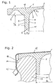
- the sealing element 1 of Fig. 1 consists of a disc 2, to which a hollow cylindrical portion 3 is integrally formed.
- the disc 2 has an edge portion 4 which projects beyond the hollow cylindrical portion 3, and which has a circumferential sealing groove 5 which is adapted to abut the end face of a bottle opening and to form a tight seal.
- the hollow cylindrical portion 3 has on a bottom a rounded portion 6, which is to ensure easy insertion of the sealing element 1 in the bottle opening.
- the hollow cylindrical section 3 merges with a toroidal transition surface 7 into the pane 2.
- the outer peripheral surface 8 and the inner surface 9 of the hollow cylindrical portion 3 are parallel in a central region in section, that is concentric. This region of the hollow cylindrical section 3 with the height h as an axial extension is called the middle section 11 and adjoins the top of an insertion section 10 which has the rounding 6.
- At the top of the central portion 11 connects to a base portion 12 which is bounded on the inside by the toroidal transition surface 7, and connects to the outside of the seal groove 5.
- the radius R 1 of the toroidal transition surface 7 is about twice as large as the thickness D in the region of the central portion 11, arises in the region of the base portion 12 a material accumulation, which causes a relatively high rigidity at the base of the hollow cylindrical portion 3. A stiffness in this area has a positive effect on the quality and intensity of the opening noise.
- Fig. 2 shows a bottle closure using the sealing element 1 of Fig. 1.
- the bottle closure consists of a metal cap 12, in which the sealing element 1 is formed.
- the only partially illustrated bottle is designated 13.
- the metal cap 12 of the bottle closure engages in the usual way an annular bead 14 in the region of the bottle opening with a beaded edge region 15, whereby a positive connection is made.
- the sealing groove 5 adapts to the outer surface 16 of the bottle 13 and provides a reliable seal in this area.
- the hollow cylindrical portion 3 abuts the inner surface 17 of the bottle 13 to provide additional sealing. It is essential, however, that for a very short period during the opening of the bottle 13 in this area remains a seal, even if the seal groove 5 is already lifted from the bottle 13. Only when the bottle cap is lifted so far from the bottle 13, that the hollow cylindrical portion 3 of the bottle 13, the desired opening sound is generated.
- Fig. 3 shows an embodiment of the invention, in which the radius R 1 of the toroidal transition surface 7 is significantly smaller than in the embodiment described above.
- the insertion portion has a chamfer 18 which extends at an angle of approximately 45 ° to the axis of the hollow cylindrical portion 3.
- FIG. 4 shows a variant which substantially corresponds to FIG. 1 and FIG. 2, with the difference that the length L of the hollow cylindrical section 3 is enlarged compared to this embodiment variant.
- an improved seal can be achieved in the area of the outer surface 8, and an improved opening sound can be achieved.
- Bottle closures with such a sealing element 1 are more susceptible to damage, since the insertion portion 10 of the sealing element 1, in contrast to the embodiment of Fig. 1 and Fig. 2 protrudes beyond the beaded edge 15 of the metal cap 12.
- the embodiment variant of FIG. 5 differs from the embodiment variants described above in that a transition surface 19 is provided which forms a direct transition from the substantially trapezoidal sealing groove 5 to the outer surface 8 of the hollow cylindrical section 3. With broken lines, a region 20 is shown, which is displaced by the application of the sealing element 1 on the bottle 13, whereby a relatively strong stress state in the sealing element 1 is caused. This state of stress generates a torque that biases the insertion portion 10 of the hollow cylindrical portion 3 in the direction of the arrow 21 to the outside. It has been found that a variant of this type is particularly insensitive to tolerances of the inner diameter D 1 of the bottle 13.
- the present invention makes it possible to ensure a well-sounding and powerful sound when opening a bottle, wherein the opening sound is well perceived even in the cooled state.
Landscapes
- Engineering & Computer Science (AREA)
- Mechanical Engineering (AREA)
- Closures For Containers (AREA)
Description
- Die Erfindung betrifft einen Flaschenverschluss gemäß dem Oberbegriff von Patentanspruch 1.
- Ein Flaschenverschluß der oben beschriebenen Art ist aus EP 0 798 225 A bekannt. Im Allgemeinen werden derartige Verschlüsse auch als Kronenkorken bezeichnet. Diese dienen insbesondere dazu, Flaschen zu verschließen, die kohlensäurehaltige Getränke, wie etwa Bier oder Limonaden, enthalten. Kronenkorken besitzen einen sehr einfachen Aufbau und sind kostgünstig herstellbar. Bei entsprechender Ausbildung dieser Kronenkorken wird auch ausreichende Dichtwirkung erreicht, um einen sicheren Verschluss der Flasche gewährleisten zu können und um eine ausreichende Haltbarkeit von empfindlichen Getränken, wie etwa Bier, sicherstellen zu können. Die Haltbarkeit von Bier hängt wesentlich von der Rate ab, mit der Gase durch den Verschluss diffundieren können.
- Eine alternative Ausführungsform von Flaschenverschlüssen sind sogenannte Bügelverschlüsse, bei denen ein mit einer Dichtung versehenes Verschlusselement über eine im Allgemeinen aus Draht hergestellte Hebelkonstruktion an der Flasche befestigt ist und im verschlossenen Zustand einen festen Sitz des Dichtelementes gewährleistet. Solche Bügelverschlüsse besitzen neben einer verbesserten Dichtwirkung gegenüber einem Kronenkorken den Vorteil, beim Öffnen ein kräftiges und sattes "Plopp"-Geräusch zu erzeugen. Solche Bügelverschlüsse sind jedoch aufwendig in der Herstellung und dementsprechend kostenintensiv, und mit solchen Verschlüssen ausgestatteten Flaschen lassen sich nur schwer in einen Pfandkreislauf integrieren.
- Es hat sich herausgestellt, dass Getränke, insbesondere Biere, die in Flaschen mit Bügelverschlüssen angeboten werden, bei Konsumenten vielfach als höherwertig eingeschätzt werden, selbst wenn der Inhalt identisch mit Produkten ist, die in Flaschen mit Kronenkorken angeboten werden. Ein Grund dafür ist das oben beschriebene "Plopp"-Geräusch beim Öffnen der Flasche, das bei mit Kronenkorken verschlossenen Flaschen herkömmlicher Bauart nicht auftritt.
- Aufgabe der vorliegenden Erfindung ist es, einen Flaschenverschluss der oben beschriebenen Bauart so weiterzubilden, dass ohne zusätzlichen Aufwand ein kräftiges und sattes Geräusch beim Öffnen der Flasche erreicht werden kann.
- Aus der AT 401.378 B ist ein zweiteiliger Flaschenverschluss für Sektflaschen bekannt. Der Flaschenverschluss besteht einerseits aus einem Kronenkorken herkömmlicher Bauart, das heißt aus einer Blechkappe mit einem im Inneren der Blechkappe angeordneten Dichtplättchen und einem Kunststoffstopfen aus einem hohlzylindrischen Rohrstück. Der Flaschenverschluss ist so aufgebaut, dass der Kunststoffstopfen nach dem Abnehmen des Kronenkorkens zunächst in der Öffnung der Flasche verbleibt und dann entlang einer vorgeformten Rille durchbrochen werden kann, um die Flasche zu öffnen. Bei diesem bekannten System stellen sowohl der Kunststoffstopfen als auch der Kronenkorken an sich unabhängige Verschlusssysteme dar, was unter anderem dadurch zum Ausdruck kommt, dass das Dichtplättchen des Kronenkorkens in Radialrichtung über den Kunststoffstopfen hinausragen muss, um direkt an der Flasche anzuliegen und somit eine unabhängige Dichtfläche realisieren zu können. Die Dichtwirkung des Kunststoffstopfens erfolgt primär oder ausschließlich entlang der Mantelfläche des hohlzylindrischen Rohrstückes, was eine entsprechende Pressung voraussetzt.
- Das Geräusch beim Öffnen der Flasche spielt bei einem Flaschenverschluss der oben beschriebenen Art keine Rolle, da es sich um einen vorläufigen Verschluss handelt, der nur während der Produktion verwendet wird und der nicht in Kontakt mit dem Konsumenten kommt. Im Übrigen kann eine gezielte Öffnung der Flasche bei einem solchen Verschluss nur durch das Durchbrechen des Kunststoffstopfens erfolgen, was kein nennenswertes Geräusch verursacht. Ein Verschluss dieser Art ist daher nicht geeignet, die oben dargestellten Aufgaben zu erfüllen.
- Ein weiteres Problem bei der in der AT 401.378 B beschriebenen Lösung besteht darin, dass ein solcher Flaschenverschluss nur bei Flaschen mit relativ gering toleriertem Innendurchmesser im Mündungsbereich sinnvoll angeordnet werden kann. Treten größere Toleranzen auf, dann wird der Kunststoffstopfen bei einem Teil der Flaschen einen nicht ausreichenden Anpressdruck aufweisen, um die Dichtheit zu gewährleisten. Bei einem anderen Teil der Flaschen mit relativ geringem Innendurchmesser wird es jedoch im normalen Produktionsverfahren nicht ohne Schwierigkeiten möglich sein, den Flaschenverschluss in die Flasche einzutreiben.
- Bei hochwertigen Getränkten, wie etwa Sekt, ist es möglich, bei der Flaschenherstellung relativ geringe Toleranzen einzuhalten, da die Produktionskosten der Flasche im Vergleich zum Preis des Produktes nur eine relativ untergeordnete Rolle spielen. Bei Massenprodukten wie Bier oder kohlensäurehaltigen Limonaden sind die Herstellungskosten der Flaschen kritisch, und die entsprechenden Toleranzen können nicht beliebig klein vorgeschrieben werden.
- Aus der EP 0 798 225 A ist - wie oben erwähnt - ein Kronenkorken bekannt, der einen pfropfenförmigen Einsatz aufweist. Eine ähnlich Lösung ist in der DE 1 432 107 A gezeigt. Es hat sich herausgestellt, dass in diesem Druckschriften dargestellten Lösungen nicht geeignet sind, das oben beschriebene Öffnungsgeräusch sicher und reproduzierbar zu erzeugen.
- Eine weitere Aufgabe der Erfindung ist es daher, einen Flaschenverschluss anzugeben, der auch im normalen Produktionsablauf mit herkömmlichen Flaschen störungsfrei eingesetzt werden kann.
- Erfindungsgemäß werden diese Aufgaben durch einen Flaschenverschluss mit den Merkmalen von Patentanspruch 1 gelöst.
- Insbesondere durch das Vorsehen einer Materialansammlung an der Basis des hohlzylindrischen Abschnitts wird erreicht, dass dieser hohlzylindrische Abschnitt im Bereich des Überganges zur Scheibe besonders biegesteif ist, so dass sich in diesem Bereich eine besonders gute Abstützung gegenüber der Flaschenöffnung ergibt. Mit einer solchen Konstruktion lassen sich besonders kräftige und wohlklingende Geräusche beim Öffnen der Flasche erreichen. Besonders vorteilhaft ist es in diesem Zusammenhang, wenn der hohlzylindrische Abschnitt im Bereich des Basisabschnittes auf seiner Innenseite eine torusförmige Übergangsfläche aufweist, deren Krümmungsradius im Längsschnitt größer ist als die Wandstärke im Bereich des Mittelabschnittes. Auf diese Weise ist es möglich, dass die Metallkappe durch einen Druck auf das Dichtelement in Axialrichtung im Bereich der Platte ein nach außen wirkendes Biegemoment im Bereich des hohlzylindrischen Abschnittes erzeugt, was eine weitere Verbesserung des Öffnungsgeräusches mit sich bringt. Von besonderem Vorteil ist es hier, wenn der Krümmungsradius der torusförmigen Übergangsfläche mindestens doppelt so groß ist als die Wandstärke im Bereich des Mittelabschnittes.
- Von besonderem Vorteil ist es, wenn dass das Dichtelement in einem Spritzgussvorgang an die Metallkappe angeformt ist. Wesentlich dabei ist die Erkenntnis, dass das Dichtelement fest mit der Metallkappe verbunden sein muss, um mit dieser abgezogen zu werden. Eine weitere wesentliche Voraussetzung für die Funktionsfähigkeit der Erfindung ist, dass die primäre Abdichtung im Bereich der Stirnfläche der Flaschenöffnung erfolgt, wo das Dichtelement durch die Metallkappe auf die Flasche gedrückt wird. Im Bereich des hohlzylindrischen Abschnittes des Dichtelementes erfolgt zwar ebenfalls eine Abdichtung, zufolge der unvermeidlichen Produktionstoleranzen der Flasche würde diese jedoch zumindest bei einem Teil der Flaschen nicht ausreichen, die geforderte Diffusionsfestigkeit zu gewährleisten.
- Die erfindungsgemäße Lösung ermöglicht es, einen sehr einfach aufgebauten Flaschenverschluss darzustellen, der ein sehr kräftiges und sattes "Plopp"-Geräusch beim Öffnen der Flasche ergibt, auch wenn diese eisgekühlt ist.
- Vorzugsweise ist vorgesehen, dass der hohlzylindrischer Abschnitt im geschlossenem Zustand gegenüber der Innenfläche der Flasche vorgespannt ist. Diese Vorspannung wird unter anderem dadurch erreicht, dass der Außendurchmesser des hohlzylindrischen Abschnittes im kräftefreien Zustand größer ist als der Innendurchmesser der Flasche im Öffnungsbereich.
- Eine besonders begünstigte Ausführungsvariante der Erfindung sieht vor, dass das Dichtelement aus einem Verbundwerkstoff aus Ethyl-Methyl-Acrylat und einem thermoplastischen Vulkanisat eines thermoplastischen Elastomers besteht. Im Hinblick auf die schwierigen Randbedingungen bei der Herstellung und beim Aufbringen des Flaschenverschlusses hat sich die Materialauswahl als kritisch herausgestellt. Das Material des Dichtelementes muss ausreichend weich sein, um auch bei relativ geringen Anpressdrücken eine Dichtwirkung zu erzielen und andererseits ausreichenden steif sein, um auch bei hohen Produktionsgeschwindigkeiten problemlos in die Flaschenöffnung eingedrückt werden zu können. Das obige Material erfüllt diese Forderungen in optimaler Weise und ist darüber hinaus kostenmäßig innerhalb des zulässigen Bereiches.
- Weiters ist es von besonderem Vorteil, wenn der hohlzylindrische Abschnitt des Dichtelementes eine Länge aufweist, die geringer ist als die axiale Erstreckung der Metallkappe. Üblicherweise werden die Flaschenverschlüsse von der Produktionsanlage zur Abfüllanlage als Schüttung transportiert. Die bei dem Transport auftretenden Stöße können bewirken, dass Metallkappen Dichtelemente anderer Verschlüsse beschädigen. Diese Gefahr wird dadurch minimiert, dass die Dichtelemente nicht über die vom Rand der Metallkappe aufgespannte Ebene vorragen.
- Eine besonders gute Dichtwirkung wird dadurch erreicht, dass die Dichtungsnut des Dichtelementes einem im Wesentlichen trapezförmigen Querschnitt aufweist.
- Eine weitere besonders begünstigte Ausführungsvariante der Erfindung sieht vor, dass der Basisabschnitt gegenüber dem Mittelabschnitt verdickt ist und eine Höhe aufweist, die größer ist als die Wandstärke des Mittelabschnittes. Auf diese Weise wird erreicht, dass der hohlzylindrische Abschnitt im Bereich des Überganges zur Scheibe besonders biegesteif ist, so dass sich in diesem Bereich eine besonders gute Abstützung gegenüber der Flaschenöffnung ergibt. Mit einer solchen Konstruktion lassen sich besonders kräftige und wohlklingende Geräusche beim Öffnen der Flasche erreichen. Besonders vorteilhaft ist es in diesem Zusammenhang, wenn der Krümmungsradius der torusförmigen Übergangsfläche mindestens doppelt so groß ist als die Wandstärke im Bereich des Mittelabschnittes. Auf diese Weise ist es möglich, dass die Metallkappe durch einen Druck auf das Dichtelement in Axialrichtung im Bereich der Platte ein nach außen wirkendes Biegemoment im Bereich des hohlzylindrischen Abschnittes erzeugt, was eine weitere Verbesserung des Öffnungsgeräusches mit sich bringt. Von besonderem Vorteil ist es hier, wenn der Krümmungsradius der torusförmigen Übergangsfläche mindestens doppelt so groß ist als die Wandstärke im Bereich des Mittelabschnittes.
- Eine weitere günstige Ausführungsvariante der Erfindung sieht vor, dass der Basisabschnitt außen kegelstumpfförmig ausgebildet ist und in Axialrichtung mehr als die Hälfte de hohlzylindrischen Abschnittes ausmacht. Insbesondere kann dabei der Basisabschnitt einen direkten Übergang in die trapezförmige Nut aufweisen. Besonders günstig ist es bei dieser Ausführungsvariante, wenn im kräftefreien Zustand der Außendurchmesser am Ende des Basisabschnittes deutlich größer ist als der Innendurchmesser der Flasche im Bereich der Öffnung. Dadurch wird beim Eintreiben des Flaschenverschlusses während der Produktion im Basisabschnitt des hohlzylindrischen Abschnittes eine besonders starke Verformung herbeigeführt. Dies setzt zwar relativ große Kräfte beim Eintreiben voraus, die jedoch zu keiner Zerstörung oder unzulässigen Verformung des Dichtelementes führen, da dieses zu dem Zeitpunkt, wo diese Kräfte auftreten, bereits relativ weit in die Flasche eingetrieben ist. Es hat sich herausgestellt, dass bei einer solchen Ausführung ein Spannungszustand eintritt, der ein besonders ansprechendes Öffnungsgeräusch erzeugt.
- In besonders bevorzugter Weise ist vorgesehen, dass das Dichtelement zumindest teilweise aus einem unter Feuchtigkeitseinwirkung quellenden Material aufgebaut ist. Sogenannte Superabsorber werden üblicherweise dazu eingesetzt, um unerwünschte Feuchtigkeit aufzunehmen und Gegenstände trocken zu halten. Dies ist beispielsweise in Babywindeln oder Lebensmittelverpackungen der Fall. Superabsorber auf der Basis von Acrylsäure sind unter den Bezeichnungen Norsocryl®, Aquakeep® und Favor® im Handel. Es können aber auch Derivate aus phosphorylierten, carbamidierten Stärken eingesetzt werden, wie etwa ein unter der Bezeichnung Carbion® S erhältliches Produkt. Durch das Aufquellen wird eine zusätzliche Spannung im hohlzylindrischen Abschnitt erzeugt, die das Öffnungsgeräusch verstärkt, ohne dass das Einführen des Dichtelements beim Verschließen der Flasche behindert wird.
- In der Folge wird die vorliegenden Erfindung anhand der in den Figuren dargestellten Ausführungsbeispiele näher erläutert. Es zeigen
- Fig. 1
- eine erste Ausführungsvariante eines erfindungsgemäßen Dichtelementes im Schnitt,
- Fig. 2
- einen auf eine Flasche aufgesetzten Flaschenverschluss mit dem Dichtelement von Fig. 1,
- Fig. 3 und Fig. 4
- weitere Ausführungsvarianten von Dichtelementen in einem Schnitt entsprechend Fig. 1 und
- Fig. 5
- eine weitere Ausführungsvariante eines Flaschenverschlusses im Schnitt.
- Das Dichtelement 1 von Fig. 1 besteht aus einer Scheibe 2, an die ein hohlzylindrischer Abschnitt 3 angeformt ist. Die Scheibe 2 besitzt einen Randbereich 4, der über den hohlzylindrischen Abschnitt 3 hinausragt, und der eine umlaufende Dichtungsnut 5 aufweist, die dazu ausgebildet ist, an der Stirnfläche einer Flaschenöffnung anzuliegen und einen dichten Abschluss zu bilden.
- Der hohlzylindrische Abschnitt 3 besitzt an einer Unterseite einen abgerundeten Bereich 6, der ein problemloses Einführen des Dichtelementes 1 in die Flaschenöffnung sicherstellen soll. An der Innenseite geht der hohlzylindrische Abschnitt 3 mit einer torusförmigen Übergangsfläche 7 in die Scheibe 2 über. Die äußere Umfangsfläche 8 und die Innenfläche 9 des hohlzylindrischen Abschnittes 3 sind in einem mittleren Bereich im Schnitt parallel, das heißt konzentrisch. Dieser Bereich des hohlzylindrischen Abschnittes 3 mit der Höhe h als axialer Erstreckung wird Mittelabschnitt 11 genannt und schließt oben an einen Einführungsabschnitt 10 an, der die Abrundung 6 aufweist. An der Oberseite schließt an den Mittelabschnitt 11 ein Basisabschnitt 12 an, der an der Innenseite durch die torusförmige Übergangsfläche 7 begrenzt ist, und an den außen die Dichtungsnut 5 anschließt. Da der Radius R1 der torusförmigen Übergangsfläche 7 etwa doppelt so groß ist, wie die Dicke D im Bereich des Mittelabschnittes 11, entsteht im Bereich des Basisabschnittes 12 eine Materialansammlung, die eine relativ große Steifigkeit an der Basis des hohlzylindrischen Abschnittes 3 verursacht. Eine Steifigkeit in diesem Bereich wirkt sich positiv auf Qualität und Intensität des Öffnungsgeräusches.
- Fig. 2 zeigt einen Flaschenverschluss unter Verwendung des Dichtelementes 1 von Fig. 1. Der Flaschenverschluss besteht aus einer Metallkappe 12, in die das Dichtelement 1 eingeformt ist. Die nur teilweise dargestellte Flasche ist mit 13 bezeichnet. Die Metallkappe 12 des Flaschenverschlusses umgreift in üblicher Weise einen Ringwulst 14 im Bereich der Flaschenöffnung mit einem gebördelten Randbereich 15, wodurch eine formschlüssige Verbindung hergestellt wird. Die Dichtungsnut 5 passt sich an die Außenfläche 16 der Flasche 13 an und ergibt in diesem Bereich eine zuverlässige Abdichtung. Zusätzlich dazu liegt der hohlzylindrische Abschnitt 3 an der Innenfläche 17 der Flasche 13 an, um eine zusätzliche Abdichtung zu ergeben. Wesentlich ist jedoch, dass für einen sehr kurzen Zeitraum während des Öffnens der Flasche 13 in diesem Bereich eine Abdichtung verbleibt, auch wenn die Dichtungsnut 5 bereits von der Flasche 13 abgehoben ist. Erst wenn der Flaschenverschluss so weit von der Flasche 13 abgehoben ist, dass sich der hohlzylindrische Abschnitt 3 von der Flasche 13 entfernt, wird das gewünschte Öffnungsgeräusch erzeugt.
- Fig. 3 zeigt eine Ausführungsvariante der Erfindung, bei der der Radius R1 der torusförmigen Übergangsfläche 7 deutlich kleiner ist, als bei der oben beschriebenen Ausführungsvariante. Darüber hinaus besitzt der Einführungsabschnitt eine Abschrägung 18, die sich in einem Winkel von etwa 45° zu Achse des hohlzylindrischen Abschnittes 3 erstreckt. Mit einem Verschluss von Fig. 3 werden relativ gute Ergebnisse erzielt, wenn die Toleranz des Innendurchmessers D1 der Flasche 13 relativ gering ist.
- Fig. 4 zeigt eine Ausführungsvariante, die im Wesentlichen der Fig. 1 und Fig. 2 entspricht, mit dem Unterschied, dass die Länge L des hohlzylindrischen Abschnittes 3 gegenüber dieser Ausführungsvariante vergrößert ist. Auf diese Weise kann im Bereich der Außenfläche 8 eine verbesserte Abdichtung erzielt werden, und es kann ein verbessertes Öffnungsgeräusch erzielt werden. Flaschenverschlüsse mit einem solchen Dichtelement 1 sind jedoch anfälliger gegenüber Beschädigungen, da der Einführungsabschnitt 10 des Dichtelementes 1 im Gegensatz zu der Ausführung der Fig. 1 und Fig. 2 über den gebördelten Rand 15 der Metallkappe 12 hinausragt.
- Die Ausführungsvariante von Fig. 5 unterscheidet sich von den oben beschriebenen Ausführungsvarianten dadurch, dass eine Übergangsfläche 19 vorgesehen ist, die einen direkten Übergang von der im Wesentlichen trapezförmigen Dichtungsnut 5 zur Außenfläche 8 des hohlzylindrischen Abschnittes 3 bildet. Mit unterbrochenen Linien ist ein Bereich 20 dargestellt, der durch das Aufbringen des Dichtelementes 1 auf die Flasche 13 verdrängt wird, wodurch ein relativ starker Spannungszustand im Dichtelement 1 hervorgerufen wird. Dieser Spannungszustand erzeugt ein Drehmoment, das den Einführungsabschnitt 10 des hohlzylindrischen Abschnittes 3 im Sinn des Pfeils 21 nach außen vorspannt. Es hat sich herausgestellt, dass eine Ausführungsvariante dieser Art besonders unempfindlich gegenüber Toleranzen des Innendurchmessers D1 der Flasche 13 ist.
- Die vorliegende Erfindung ermöglicht es, ein wohlklingendes und kräftiges Geräusch beim Öffnen einer Flasche sicherzustellen, wobei das Öffnungsgeräusch auch in gekühltem Zustand gut wahrnehmbar ist.
Claims (13)
- Flaschenverschluss bestehend aus einer plastisch verformbaren Metallkappe (12), die die Flasche (13) abdeckt und die einen gebördelten Randbereich (15) aufweist, der die Flasche (13) in verschlossenem Zustand formschlüssig umgreift, sowie aus einem fest mit der Metallkappe (12) verbundenen Dichtelement (1), das im Öffnungsbereich der Flasche (13) an dieser anliegt und die Flasche (13) verschließt, wobei das Dichtelement (1) aus einer die Öffnung der Flasche (13) verschließenden Scheibe (2) besteht, an die ein im Wesentlichen hohlzylindrischer Abschnitt (3) anschließt, der in verschlossenem Zustand in die Öffnung der Flasche (13) eingeführt ist und an der Innenwand der Flasche (13) anliegt, und wobei ein Randbereich (4) der Scheibe (2) über den hohlzylindrischen Abschnitt (3) hinausragt, um auf der Flasche (13) aufzuliegen, und wobei weiters der Randbereich (4) des Dichtelementes (1) eine Dichtungsnut (5) aufweist, die zur Dichtung gegenüber der Flasche (13) im Bereich ihrer Stirnfläche bestimmt ist, dadurch gekennzeichnet, dass der hohlzylindrische Abschnitt (3) des Dichtelementes (1) aus einem Basisabschnitt (12), einem Mittelabschnitt (11) mit im Wesentlichen zylindrische Innen- und Außenfläche (9, 8) und einem Einführungsabschnitt (10) mit einer Abschrägung oder Abrundung am Ende besteht, und dass der hohlzylindrische Abschnitt (3) im Bereich des Basisabschnittes (12) auf seiner Innenseite eine torusförmige Übergangsfläche (7) aufweist, so dass gemeinsam mit dem Übergang zur Dichtungsnut (5) eine Materialansammlung gebildet ist.
- Flaschenverschluss nach Anschluss 1, dadurch gekennzeichnet, dass der hohlzylindrischer Abschnitt (3) im geschlossenem Zustand gegenüber der Innenfläche (17) der Flasche (13) vorgespannt ist.
- Flaschenverschluss nach Anspruch 1 oder 2, dadurch gekennzeichnet, dass das Dichtelement (1) aus einem Verbundwerkstoff aus Ethyl-Methyl-Acrylat und einem thermoplastischen Vulkanisat eines thermoplastischen Elastomers besteht.
- Flaschenverschluss nach einem der Ansprüche 1 bis 3, dadurch gekennzeichnet, dass das Dichtelement (1) in einem Spritzgussvorgang an die Metallkappe (12) angeformt ist.
- Flaschenverschluss nach einem der Ansprüche 1 bis 4, dadurch gekennzeichnet, dass der hohlzylindrische Abschnitt (3) des Dichtelementes (1) eine Länge (L) aufweist, die geringer ist als die axiale Erstreckung der Metallkappe (12).
- Flaschenverschluss nach einem der Ansprüche 1 bis 5, dadurch gekennzeichnet, dass die Dichtungsnut (5) des Dichtelementes (1) einem im Wesentlichen trapezförmigen Querschnitt aufweist.
- Flaschenverschluss nach einem der Ansprüche 1 bis 6, dadurch gekennzeichnet, dass der Basisabschnitt (12) eine Höhe (h) aufweist, die größer ist als die Wandstärke (D) des Mittelabschnittes (11).
- Flaschenverschluss nach Anspruch 7, dadurch gekennzeichnet, dass die torusförmige Übergangsfläche (7) im Längsschnitt einen Krümmungsradius (R1) aufweist, der größer ist als die Wandstärke (D) im Bereich des Mittelabschnittes (11).
- Flaschenverschluss nach Anspruch 8, dadurch gekennzeichnet, dass der Krümmungsradius der torusförmigen Übergangsfläche (7) mindestens doppelt so groß ist als die Wandstärke (D) im Bereich des Mittelabschnittes (11).
- Flaschenverschluss nach einem der Ansprüche 7 bis 9, dadurch gekennzeichnet, dass der Basisabschnitt (12) außen kegelstumpfförmig ausgebildet ist und in Axialrichtung mehr als die Hälfte des hohlzylindrischen Abschnittes (3) ausmacht.
- Flaschenverschluss nach Anspruch 10, dadurch gekennzeichnet, dass der Basisabschnitt (12) einen direkten Übergang in die trapezförmige Nut aufweist.
- Flaschenverschluss nach Anspruch 10 oder 11, dadurch gekennzeichnet, dass im kräftefreien Zustand der Außendurchmesser am Ende des Basisabschnittes (12) deutlich größer ist als der Innendurchmesser der Flasche im Bereich der Öffnung.
- Flaschenverschluss nach einem der Ansprüche 1 bis 12, dadurch gekennzeichnet, dass das Dichtelement (1) zumindest teilweise aus einem unter Feuchtigkeitseinwirkung quellenden Material aufgebaut ist.
Priority Applications (1)
| Application Number | Priority Date | Filing Date | Title |
|---|---|---|---|
| SI200430254T SI1575839T1 (sl) | 2003-01-30 | 2004-01-29 | Zapirka steklenice |
Applications Claiming Priority (3)
| Application Number | Priority Date | Filing Date | Title |
|---|---|---|---|
| AT1422003 | 2003-01-30 | ||
| AT1422003 | 2003-01-30 | ||
| PCT/AT2004/000035 WO2004067402A1 (de) | 2003-01-30 | 2004-01-29 | Flaschenverschluss |
Publications (3)
| Publication Number | Publication Date |
|---|---|
| EP1575839A1 EP1575839A1 (de) | 2005-09-21 |
| EP1575839B1 true EP1575839B1 (de) | 2007-01-10 |
| EP1575839B8 EP1575839B8 (de) | 2007-03-14 |
Family
ID=32777514
Family Applications (1)
| Application Number | Title | Priority Date | Filing Date |
|---|---|---|---|
| EP04706092A Expired - Lifetime EP1575839B8 (de) | 2003-01-30 | 2004-01-29 | Flaschenverschluss |
Country Status (5)
| Country | Link |
|---|---|
| EP (1) | EP1575839B8 (de) |
| DE (1) | DE502004002619D1 (de) |
| ES (1) | ES2282845T3 (de) |
| SI (1) | SI1575839T1 (de) |
| WO (1) | WO2004067402A1 (de) |
Families Citing this family (4)
| Publication number | Priority date | Publication date | Assignee | Title |
|---|---|---|---|---|
| AT501099B8 (de) * | 2004-12-06 | 2007-02-15 | Ottakringer Brauerei Ag | Vorrichtung zum öffnen einer mit einem kronenkorken verschlossenen flasche |
| DE102007050397B4 (de) * | 2006-10-18 | 2009-01-15 | D'angelico, Angelo | Behälterverschluss mit Mittel zur Geräuscherzeugung |
| DE202009008058U1 (de) | 2009-06-10 | 2010-10-28 | Schopf, Walter, Dipl.-Ing. | Getränkeflaschenverschluss mit integrierten elektrischen/elektronischen Elementen zur Erzeugung akustischer Effekte |
| DE102009024451A1 (de) | 2009-06-10 | 2010-12-16 | Schopf, Walter, Dipl.-Ing. | Weinflaschen-Schraubverschluss mit "Plopp"-Effekt |
Family Cites Families (6)
| Publication number | Priority date | Publication date | Assignee | Title |
|---|---|---|---|---|
| DE1186354B (de) * | 1952-08-13 | 1965-01-28 | Dr Hellmut Golde | Verschlussstueck fuer Flaschen |
| FR1335073A (fr) * | 1962-07-03 | 1963-08-16 | Corre Soc | Perfectionnement aux systèmes de bouchage de bouteilles |
| DE1432107A1 (de) * | 1962-12-22 | 1968-12-12 | Bouchon Rapid Les Darcins | Flaschenschnellverschluss |
| ES2000835A6 (es) * | 1986-08-04 | 1988-03-16 | Bosch Garces Jose Manuel | Tapon roscado multiuso con capsula de cierre |
| IT1287222B1 (it) * | 1996-03-25 | 1998-08-04 | Stelplast Di Vidale Stelvio & | Tappo perfezionato per bottiglie atto ad esser impiegato nella prima fase di lavorazione di spumanti col metodo champenois e per la |
| FR2795052B1 (fr) * | 1999-06-15 | 2001-08-24 | Lorraine Capsules Metall | Dispositif de bouchage temporaire pour bouteille |
-
2004
- 2004-01-29 ES ES04706092T patent/ES2282845T3/es not_active Expired - Lifetime
- 2004-01-29 SI SI200430254T patent/SI1575839T1/sl unknown
- 2004-01-29 DE DE502004002619T patent/DE502004002619D1/de not_active Expired - Lifetime
- 2004-01-29 EP EP04706092A patent/EP1575839B8/de not_active Expired - Lifetime
- 2004-01-29 WO PCT/AT2004/000035 patent/WO2004067402A1/de not_active Ceased
Also Published As
| Publication number | Publication date |
|---|---|
| EP1575839B8 (de) | 2007-03-14 |
| ES2282845T3 (es) | 2007-10-16 |
| WO2004067402A1 (de) | 2004-08-12 |
| SI1575839T1 (sl) | 2007-08-31 |
| DE502004002619D1 (de) | 2007-02-22 |
| EP1575839A1 (de) | 2005-09-21 |
Similar Documents
| Publication | Publication Date | Title |
|---|---|---|
| EP1117596B1 (de) | Behälter mit einer kunststoffverschlusskappe mit abtrennbarem garantieband und innendichtung | |
| DE10297200B4 (de) | Verschluss für Behälteröffnungen | |
| DE3854669T2 (de) | Verschlusskappe mit dichtung und verfahren zur herstellung der verschlussdichtung. | |
| EP0549987A1 (de) | Aluminiumflasche | |
| EP1456092A2 (de) | BEH LTER, INSBESONDERE GETR NKEFLASCHE | |
| DE69202065T2 (de) | Stopfen zum Verschliessen von Flüssigkeitsbehältern. | |
| EP1092640A1 (de) | Garantieverschluss | |
| EP0069168A1 (de) | Bausatz für einen Kappenverschluss | |
| EP1451081B1 (de) | Verschliessbare getränkeflasche | |
| DE68917938T2 (de) | Deckel ohne innenbekleidung für kohlensäurehaltige getränkebehälter. | |
| DE2555149A1 (de) | Verschluss aus kunststoff an einem behaelter | |
| DE69916102T2 (de) | Mehrteiliger verschlussstopfen mit kontrollierter durchlässigkeit | |
| EP1575839B1 (de) | Flaschenverschluss | |
| DE69702841T2 (de) | Zusammengesetzter Verschluss, Verfahren zu seiner Zusammenstellung, und mit dem Verschluss ausgerüsteter Behälter | |
| EP2666730A1 (de) | Verschlusskappe mit Originalitätsring | |
| DE60004029T2 (de) | Behälterverschluss | |
| DE2704454C2 (de) | Behälterverschluß | |
| EP0620164B1 (de) | Verfahren zur Herstellung eines Verschlusses für eine Flasche oder dergleichen | |
| DE602004006255T2 (de) | Schraubverschluss für Behälter | |
| AT7405U1 (de) | Flaschenverschluss | |
| AT7406U1 (de) | Flaschenverschluss | |
| DE602004001232T2 (de) | Verschluss für einen Behälter, insbesondere eine Flasche | |
| EP2989018B1 (de) | Flaschenverschluss zum verschliessen einer flasche | |
| DE2530650C3 (de) | Drehverschluß zum Verschließen von unter Innendruck stehenden Behältern | |
| DE4225092A1 (de) | Flaschenstoepsel aus elastischem kunststoff |
Legal Events
| Date | Code | Title | Description |
|---|---|---|---|
| PUAI | Public reference made under article 153(3) epc to a published international application that has entered the european phase |
Free format text: ORIGINAL CODE: 0009012 |
|
| 17P | Request for examination filed |
Effective date: 20050625 |
|
| AK | Designated contracting states |
Kind code of ref document: A1 Designated state(s): AT BE BG CH CY CZ DE DK EE ES FI FR GB GR HU IE IT LI LU MC NL PT RO SE SI SK TR |
|
| AX | Request for extension of the european patent |
Extension state: AL LT LV MK |
|
| DAX | Request for extension of the european patent (deleted) | ||
| GRAP | Despatch of communication of intention to grant a patent |
Free format text: ORIGINAL CODE: EPIDOSNIGR1 |
|
| GRAS | Grant fee paid |
Free format text: ORIGINAL CODE: EPIDOSNIGR3 |
|
| GRAA | (expected) grant |
Free format text: ORIGINAL CODE: 0009210 |
|
| AK | Designated contracting states |
Kind code of ref document: B1 Designated state(s): AT BE BG CH CY CZ DE DK EE ES FI FR GB GR HU IE IT LI LU MC NL PT RO SE SI SK TR |
|
| PG25 | Lapsed in a contracting state [announced via postgrant information from national office to epo] |
Ref country code: DK Free format text: LAPSE BECAUSE OF FAILURE TO SUBMIT A TRANSLATION OF THE DESCRIPTION OR TO PAY THE FEE WITHIN THE PRESCRIBED TIME-LIMIT Effective date: 20070110 Ref country code: FI Free format text: LAPSE BECAUSE OF FAILURE TO SUBMIT A TRANSLATION OF THE DESCRIPTION OR TO PAY THE FEE WITHIN THE PRESCRIBED TIME-LIMIT Effective date: 20070110 Ref country code: IE Free format text: LAPSE BECAUSE OF FAILURE TO SUBMIT A TRANSLATION OF THE DESCRIPTION OR TO PAY THE FEE WITHIN THE PRESCRIBED TIME-LIMIT Effective date: 20070110 |
|
| REG | Reference to a national code |
Ref country code: GB Ref legal event code: FG4D Free format text: NOT ENGLISH |
|
| PG25 | Lapsed in a contracting state [announced via postgrant information from national office to epo] |
Ref country code: MC Free format text: LAPSE BECAUSE OF NON-PAYMENT OF DUE FEES Effective date: 20070131 |
|
| REG | Reference to a national code |
Ref country code: IE Ref legal event code: FG4D Free format text: LANGUAGE OF EP DOCUMENT: GERMAN |
|
| REF | Corresponds to: |
Ref document number: 502004002619 Country of ref document: DE Date of ref document: 20070222 Kind code of ref document: P |
|
| PG25 | Lapsed in a contracting state [announced via postgrant information from national office to epo] |
Ref country code: SE Free format text: LAPSE BECAUSE OF FAILURE TO SUBMIT A TRANSLATION OF THE DESCRIPTION OR TO PAY THE FEE WITHIN THE PRESCRIBED TIME-LIMIT Effective date: 20070410 Ref country code: BG Free format text: LAPSE BECAUSE OF FAILURE TO SUBMIT A TRANSLATION OF THE DESCRIPTION OR TO PAY THE FEE WITHIN THE PRESCRIBED TIME-LIMIT Effective date: 20070410 |
|
| GBT | Gb: translation of ep patent filed (gb section 77(6)(a)/1977) |
Effective date: 20070418 |
|
| REG | Reference to a national code |
Ref country code: CH Ref legal event code: NV Representative=s name: ISLER & PEDRAZZINI AG |
|
| PG25 | Lapsed in a contracting state [announced via postgrant information from national office to epo] |
Ref country code: PT Free format text: LAPSE BECAUSE OF FAILURE TO SUBMIT A TRANSLATION OF THE DESCRIPTION OR TO PAY THE FEE WITHIN THE PRESCRIBED TIME-LIMIT Effective date: 20070611 |
|
| ET | Fr: translation filed | ||
| REG | Reference to a national code |
Ref country code: IE Ref legal event code: FD4D |
|
| REG | Reference to a national code |
Ref country code: HU Ref legal event code: AG4A Ref document number: E001754 Country of ref document: HU |
|
| REG | Reference to a national code |
Ref country code: CH Ref legal event code: PCAR Free format text: ISLER & PEDRAZZINI AG;POSTFACH 1772;8027 ZUERICH (CH) |
|
| REG | Reference to a national code |
Ref country code: ES Ref legal event code: FG2A Ref document number: 2282845 Country of ref document: ES Kind code of ref document: T3 |
|
| PLBE | No opposition filed within time limit |
Free format text: ORIGINAL CODE: 0009261 |
|
| STAA | Information on the status of an ep patent application or granted ep patent |
Free format text: STATUS: NO OPPOSITION FILED WITHIN TIME LIMIT |
|
| 26N | No opposition filed |
Effective date: 20071011 |
|
| BERE | Be: lapsed |
Owner name: OTTAKRINGER BRAUERIE AG Effective date: 20070131 |
|
| PG25 | Lapsed in a contracting state [announced via postgrant information from national office to epo] |
Ref country code: BE Free format text: LAPSE BECAUSE OF NON-PAYMENT OF DUE FEES Effective date: 20070131 Ref country code: RO Free format text: LAPSE BECAUSE OF FAILURE TO SUBMIT A TRANSLATION OF THE DESCRIPTION OR TO PAY THE FEE WITHIN THE PRESCRIBED TIME-LIMIT Effective date: 20070110 |
|
| PG25 | Lapsed in a contracting state [announced via postgrant information from national office to epo] |
Ref country code: GR Free format text: LAPSE BECAUSE OF FAILURE TO SUBMIT A TRANSLATION OF THE DESCRIPTION OR TO PAY THE FEE WITHIN THE PRESCRIBED TIME-LIMIT Effective date: 20070411 |
|
| PG25 | Lapsed in a contracting state [announced via postgrant information from national office to epo] |
Ref country code: HU Free format text: LAPSE BECAUSE OF NON-PAYMENT OF DUE FEES Effective date: 20080130 |
|
| PG25 | Lapsed in a contracting state [announced via postgrant information from national office to epo] |
Ref country code: EE Free format text: LAPSE BECAUSE OF FAILURE TO SUBMIT A TRANSLATION OF THE DESCRIPTION OR TO PAY THE FEE WITHIN THE PRESCRIBED TIME-LIMIT Effective date: 20070110 |
|
| PG25 | Lapsed in a contracting state [announced via postgrant information from national office to epo] |
Ref country code: CY Free format text: LAPSE BECAUSE OF FAILURE TO SUBMIT A TRANSLATION OF THE DESCRIPTION OR TO PAY THE FEE WITHIN THE PRESCRIBED TIME-LIMIT Effective date: 20070110 |
|
| PG25 | Lapsed in a contracting state [announced via postgrant information from national office to epo] |
Ref country code: LU Free format text: LAPSE BECAUSE OF NON-PAYMENT OF DUE FEES Effective date: 20070129 |
|
| PG25 | Lapsed in a contracting state [announced via postgrant information from national office to epo] |
Ref country code: TR Free format text: LAPSE BECAUSE OF FAILURE TO SUBMIT A TRANSLATION OF THE DESCRIPTION OR TO PAY THE FEE WITHIN THE PRESCRIBED TIME-LIMIT Effective date: 20070110 |
|
| REG | Reference to a national code |
Ref country code: FR Ref legal event code: PLFP Year of fee payment: 13 |
|
| PG25 | Lapsed in a contracting state [announced via postgrant information from national office to epo] |
Ref country code: AT Free format text: THE PATENT HAS BEEN ANNULLED BY A DECISION OF A NATIONAL AUTHORITY Effective date: 20090129 |
|
| PGRI | Patent reinstated in contracting state [announced from national office to epo] |
Ref country code: AT Effective date: 20130206 |
|
| REG | Reference to a national code |
Ref country code: FR Ref legal event code: PLFP Year of fee payment: 14 |
|
| REG | Reference to a national code |
Ref country code: FR Ref legal event code: PLFP Year of fee payment: 15 |
|
| PGFP | Annual fee paid to national office [announced via postgrant information from national office to epo] |
Ref country code: NL Payment date: 20180130 Year of fee payment: 15 |
|
| PGFP | Annual fee paid to national office [announced via postgrant information from national office to epo] |
Ref country code: CZ Payment date: 20180129 Year of fee payment: 15 Ref country code: ES Payment date: 20180213 Year of fee payment: 15 Ref country code: GB Payment date: 20180130 Year of fee payment: 15 Ref country code: CH Payment date: 20180129 Year of fee payment: 15 |
|
| PGFP | Annual fee paid to national office [announced via postgrant information from national office to epo] |
Ref country code: SI Payment date: 20180126 Year of fee payment: 15 Ref country code: IT Payment date: 20180129 Year of fee payment: 15 Ref country code: FR Payment date: 20180131 Year of fee payment: 15 Ref country code: HU Payment date: 20180321 Year of fee payment: 15 Ref country code: SK Payment date: 20180129 Year of fee payment: 15 Ref country code: AT Payment date: 20180131 Year of fee payment: 15 |
|
| PGFP | Annual fee paid to national office [announced via postgrant information from national office to epo] |
Ref country code: DE Payment date: 20180329 Year of fee payment: 15 |
|
| REG | Reference to a national code |
Ref country code: DE Ref legal event code: R119 Ref document number: 502004002619 Country of ref document: DE |
|
| REG | Reference to a national code |
Ref country code: CH Ref legal event code: PL |
|
| REG | Reference to a national code |
Ref country code: NL Ref legal event code: MM Effective date: 20190201 |
|
| REG | Reference to a national code |
Ref country code: AT Ref legal event code: MM01 Ref document number: 351138 Country of ref document: AT Kind code of ref document: T Effective date: 20190129 |
|
| GBPC | Gb: european patent ceased through non-payment of renewal fee |
Effective date: 20190129 |
|
| REG | Reference to a national code |
Ref country code: SK Ref legal event code: MM4A Ref document number: E 2102 Country of ref document: SK Effective date: 20190129 |
|
| PG25 | Lapsed in a contracting state [announced via postgrant information from national office to epo] |
Ref country code: SK Free format text: LAPSE BECAUSE OF NON-PAYMENT OF DUE FEES Effective date: 20190129 Ref country code: DE Free format text: LAPSE BECAUSE OF NON-PAYMENT OF DUE FEES Effective date: 20190801 Ref country code: FR Free format text: LAPSE BECAUSE OF NON-PAYMENT OF DUE FEES Effective date: 20190131 Ref country code: CZ Free format text: LAPSE BECAUSE OF NON-PAYMENT OF DUE FEES Effective date: 20190129 Ref country code: NL Free format text: LAPSE BECAUSE OF NON-PAYMENT OF DUE FEES Effective date: 20190201 Ref country code: SI Free format text: LAPSE BECAUSE OF NON-PAYMENT OF DUE FEES Effective date: 20190130 |
|
| PG25 | Lapsed in a contracting state [announced via postgrant information from national office to epo] |
Ref country code: CH Free format text: LAPSE BECAUSE OF NON-PAYMENT OF DUE FEES Effective date: 20190131 Ref country code: LI Free format text: LAPSE BECAUSE OF NON-PAYMENT OF DUE FEES Effective date: 20190131 Ref country code: GB Free format text: LAPSE BECAUSE OF NON-PAYMENT OF DUE FEES Effective date: 20190129 Ref country code: AT Free format text: LAPSE BECAUSE OF NON-PAYMENT OF DUE FEES Effective date: 20190129 |
|
| REG | Reference to a national code |
Ref country code: SI Ref legal event code: KO00 Effective date: 20190926 |
|
| PG25 | Lapsed in a contracting state [announced via postgrant information from national office to epo] |
Ref country code: IT Free format text: LAPSE BECAUSE OF NON-PAYMENT OF DUE FEES Effective date: 20190129 |
|
| REG | Reference to a national code |
Ref country code: ES Ref legal event code: FD2A Effective date: 20200310 |
|
| PG25 | Lapsed in a contracting state [announced via postgrant information from national office to epo] |
Ref country code: ES Free format text: LAPSE BECAUSE OF NON-PAYMENT OF DUE FEES Effective date: 20190130 |
|
| PG25 | Lapsed in a contracting state [announced via postgrant information from national office to epo] |
Ref country code: HU Free format text: LAPSE BECAUSE OF NON-PAYMENT OF DUE FEES Effective date: 20190130 |