EP1575166A1 - Piezoelektrisches vibrationsst ck und daspiezoelektrische vibrationsst ck verwendende piezoelektrische einrichtung - Google Patents
Piezoelektrisches vibrationsst ck und daspiezoelektrische vibrationsst ck verwendende piezoelektrische einrichtung Download PDFInfo
- Publication number
- EP1575166A1 EP1575166A1 EP03778933A EP03778933A EP1575166A1 EP 1575166 A1 EP1575166 A1 EP 1575166A1 EP 03778933 A EP03778933 A EP 03778933A EP 03778933 A EP03778933 A EP 03778933A EP 1575166 A1 EP1575166 A1 EP 1575166A1
- Authority
- EP
- European Patent Office
- Prior art keywords
- vibration
- groove
- piezoelectric
- arm
- vibration piece
- Prior art date
- Legal status (The legal status is an assumption and is not a legal conclusion. Google has not performed a legal analysis and makes no representation as to the accuracy of the status listed.)
- Withdrawn
Links
Images




Classifications
-
- H—ELECTRICITY
- H03—ELECTRONIC CIRCUITRY
- H03H—IMPEDANCE NETWORKS, e.g. RESONANT CIRCUITS; RESONATORS
- H03H9/00—Networks comprising electromechanical or electro-acoustic elements; Electromechanical resonators
- H03H9/15—Constructional features of resonators consisting of piezoelectric or electrostrictive material
- H03H9/21—Crystal tuning forks
-
- H—ELECTRICITY
- H03—ELECTRONIC CIRCUITRY
- H03H—IMPEDANCE NETWORKS, e.g. RESONANT CIRCUITS; RESONATORS
- H03H9/00—Networks comprising electromechanical or electro-acoustic elements; Electromechanical resonators
- H03H9/02—Details
- H03H9/05—Holders or supports
- H03H9/10—Mounting in enclosures
- H03H9/1007—Mounting in enclosures for bulk acoustic wave [BAW] devices
- H03H9/1014—Mounting in enclosures for bulk acoustic wave [BAW] devices the enclosure being defined by a frame built on a substrate and a cap, the frame having no mechanical contact with the BAW device
- H03H9/1021—Mounting in enclosures for bulk acoustic wave [BAW] devices the enclosure being defined by a frame built on a substrate and a cap, the frame having no mechanical contact with the BAW device the BAW device being of the cantilever type
Definitions
- the present invention relates to a piezoelectric vibration piece, a piezoelectric device comprising a package that accommodates the piezoelectric vibration piece, and a portable phone and electronic equipment using the piezoelectric device.
- Piezoelectric devices such as piezoelectric vibrators and piezoelectric oscillators each accommodating a piezoelectric vibration piece in their package are widely applied to small-sized information equipment such as HDDs (Hard Disk Drive), mobile computers, or IC cards, and mobile communications devices such as portable phones, car phones, or paging systems.
- HDDs Hard Disk Drive
- mobile computers or IC cards
- mobile communications devices such as portable phones, car phones, or paging systems.
- FIG. 11 is a schematic cross-sectional view showing an exemplary structure of such a piezoelectric device.
- a piezoelectric device 1 accommodates a piezoelectric vibration piece 3 in its package 2.
- the package 2 is in the shape of a shallow box made of an insulation material, and the internally-accommodated piezoelectric vibration piece 3 is securely fixed therein before the package is sealed by a lid body 4.
- the package 2 is formed by mold-laminating a plurality of substrates 2a, 2b, and 2c each being a ceramic green sheet before being subjected to sintering. Inside each of the substrates 2b and 2c, a hole is formed by eliminating the material at the time of substrate formation. Thereby, as shown in the drawing, a space is formed for accommodating the piezoelectric vibration piece 3.
- the piezoelectric vibration piece 3 is exemplarily formed as shown in FIG. 12 by crystal etching. As shown in the drawing, the piezoelectric vibration piece 3 is structured by a, so-called, crystal flake of a tuning fork type including a base section 5, and a pair of vibration arms 6 and 7 horizontally extending from the base section 5 in the right direction in the drawing.
- FIG. 13 shows the cross-sectional view of the vibration arm 7 cut along the line B-B.
- excitation electrodes 8a and 8b are formed, and a driving voltage is applied from outside to these excitation electrodes 8a and 8b.
- an electric field is established within the vibration arm 7 as shown by the arrows.
- the vibration arms 6 and 7 so vibrate that the tip sides thereof come near or apart as shown by an arrow A.
- the shown movement of the vibration arms 6 and 7 is extremely exaggerated, compared to the actual movement, for convenience of understanding. Extracting the vibration frequency of such vibration enables application to various signals exemplified by a control clock signal and the like.
- the vibration of the vibration arms 6 and 7 along the arrow A of FIG. 12 is the horizontal movement along the direction of arrow x of FIG. 13 (hereinafter, this direction is referred to as "horizontal direction").
- Patent Document 1 JP-A-56-65517 The issue here is that, in FIG. 13, in the manufacturing process of forming the grooves 7a and 7b in the front and back sides of the vibration arm 7, the grooves 7a and 7b are formed by half etching from the surface side and the back side of the vibration arm 7. To the vibration arm 7 having an arm width of only about 100 ⁇ m, the grooves 7a and 7b formed on the surface side and the back side as such are separately formed from the surface and back sides of the vibration arm 7. Thus, as shown in FIG. 13, in the drawing, they sometimes deviate from each other in the right and left directions, respectively.
- FIG. 14 shows the interrelation between the temperature change and the frequency shift of the piezoelectric vibration piece 3 when the vibration arms 6 and 7 vibrate correctly in the direction of arrow A
- FIG. 15 shows the interrelation between the temperature change and the frequency shift of the piezoelectric vibration piece 3 when the vibration arms 6 and 7 vibrate with the movement of the vertical component as described by referring to FIG. 13.
- the frequency f is expressed by the following equation, where k denotes a constant, E denotes an elastic constant, and I denotes a cross-sectional secondary moment.
- f k ⁇ (E ⁇ I) -2
- the temperature property will look like a quadratic curve responding to the change of the elastic constant and the elastic secondary moment.
- An object of the present invention is to provide a piezoelectric vibration piece achievable with appropriate vibration, a piezoelectric device utilizing the piezoelectric vibration piece by suppressing the movement of vibration arms in the vertical direction and by ensuring the strength along almost the entire length of the vibration arms, and a portable phone and electronic equipment using the piezoelectric device.
- a piezoelectric vibration piece that is including: a pair of vibration arms that are formed by a piezoelectric material, and are extending in the horizontal direction from a base section; a bottomed groove that is provided in each of the vibration arms, and extending in the length direction of the corresponding vibration arm; and a support section that is provided in such a manner as to cross the groove in the width direction to connect the material structuring the vibration arm separated by the groove in the width direction.
- the groove provided in each of the vibration arms is a bottomed groove.
- each of the grooves is provided with the support section so formed as to cross the groove in the width direction to integrally connect the material structuring the vibration arm separated by the groove in the width direction.
- the support section becomes a unit, in structure, especially with the bottom section of the groove to support the material structuring the vibration arm separated by the groove in the width direction, thereby preventing twisting distortion from occurring. As a result, a better strength can be achieved in the twisting direction of the corresponding vibration arm.
- the second embodiment is characterized in that, in the structure of the first embodiment, a unit section being a unit with the bottom section of the groove of the support section is so formed as to be thicker than at least an end section locating on an opening side of the groove of the support section.
- the unit section being a unit with the bottom section of the groove, of the support section is so formed as to be thicker than at least the end section locating on the opening side of the groove of this support section.
- the support section is formed in such a manner as to increase its thickness toward the bottom section of the groove. Therefore, the support section is securely connected especially to the bottom section of this groove. Accordingly, through such a secure fixation of the support section to the bottom section of this groove, in the piezoelectric vibration piece, the deformation force in the twisting direction of the vibration arms can be effectively dealt with. Thereby, the deformation in the twisting direction can be prevented from occurring in a more effective manner.
- the third embodiment is characterized in that, in either structure of the first or second embodiment, the groove is provided on a surface side and a back side of each of the vibration arms.
- each of the vibration arms is formed with the groove on its surface and back sides.
- groove formation with a fine width in the narrow vibration arm sometimes results in a deviation of the groove position on the surface side from that on the back side.
- inventors of the present invention are accepting such a process drawback as groove deviation between the surface and back sides, and if any harmful effects are caused thereby, they are solving those by forming the support section to each of the grooves on both the surface side and the back side. That is, providing a groove with a bottom section together with forming the support section to each of the grooves on the surface and back sides can effectively suppress the movement of the vertical component of each of the vibration arms.
- a fourth embodiment is characterized in that, in the structure of any one of the first to third embodiments, plural support sections are formed for each groove.
- a Cl (Crystal Impedance) value is increased as the number of the support sections formed to each groove is increased.
- a fifth embodiment is characterized in that, in the structure of any one of the first to fourth embodiments, each of the vibration arms has an arm width in a range from 50 ⁇ m to 150 ⁇ m, and the depth of the groove is 30% or more but less than 50% of the material thickness of each of the vibration arms.
- the arm width of the respective vibration arms is in a range from 50 ⁇ m to 150 ⁇ m, assuming that the depth of the groove is less than 30% of the material thickness of each of the vibration arms, the reduction effects for the Cl value cannot be enough. Thereby the Cl value fails to be practical. Further, if the depth of the groove exceeds 50% of the material thickness of the respective vibration arms, groove formation to the surface and back sides of the corresponding vibration arm becomes impossible.
- a sixth embodiment is characterized in that, in the structure of any one of the structures of the first to fifth embodiments, the groove width of the groove provided in each of the vibration arms is 40% or more of the arm width of the corresponding vibration arm.
- a seventh embodiment is characterized in that, in the structure of the sixth embodiment, the groove width of the groove provided in each of the vibration arms is 70% or more of the arm width of the corresponding vibration arm.
- the Cl value can be suppressed in the most effective manner, and with or close to 100% of the arm width of the vibration arm, groove formation to the vibration arm becomes impossible.
- a piezoelectric device accommodating a piezoelectric vibration piece in its case or package
- the piezoelectric vibration piece includes: a pair of vibration arms extending in a horizontal direction from a base section; a bottomed groove that is provided in each of the vibration arms, and is extending along the length direction of each of the vibration arms; and a support section so provided as to cross the groove in the width direction to integrally connect, the material structuring the vibration arm separated by the groove in the width direction.
- a bottomed groove is formed in each of the vibration arms of the piezoelectric vibration piece accommodated in this piezoelectric device.
- the support section provided to the groove is, especially, structured to be a unit with the bottom section of the groove to support the material structuring the vibration arm separated by the groove in the width direction. With such a structure, deformation is prevented from occurring. Thus, strength enforcement can be achieved in the twisting direction of each of the vibration arms. As such, with respect to the piezoelectric vibration piece accommodated in the piezoelectric device, the strength is ensured along almost the entire length of the vibration arm with the movement of the vibration arms suppressed in the vertical direction, thereby realizing appropriate vibration.
- a portable phone unit utilizing a piezoelectric device that is accommodating a piezoelectric vibration piece in its case or package, and a clock signal is derived for control by the piezoelectric device in which the piezoelectric vibration piece includes: a pair of vibration arms extending in a horizontal direction from a base section; a bottomed groove that is provided in each of the vibration arms, and is extending along the length direction of each of the vibration arms; and a support section so provided as to cross the groove in the width direction to integrally connect the material structuring the vibration arm separated by the groove in the width direction.
- the above-described object is achieved by, according to a tenth embodiment, electronic equipment utilizing a piezoelectric device that is accommodating a piezoelectric vibration piece in its case or package, and a clock signal is derived for control by the piezoelectric device in which the piezoelectric vibration piece includes: a pair of vibration arms extending in a horizontal direction from a base section; a bottomed groove that is provided in each of the vibration arms, and is extending along the length direction of each of the vibration arms; and a support section so provided as to cross the groove in the width direction to integrally connect the material structuring the vibration arm separated by the groove in the width direction.
- FIGS. 1 and 2 both show a first embodiment of a piezoelectric device of the present invention.
- FIG. 1 is a schematic plan view thereof
- FIG. 2 is a schematic cross-sectional view cut along line E-E of FIG. 1.
- a piezoelectric device 30 is exemplarily structuring a piezoelectric vibrator, and the piezoelectric device 30 is accommodating a piezoelectric vibration piece 32 in its package 36.
- the package 36 is formed, for example, by mold-laminating a plurality of substrates each being a ceramic green sheet made of aluminum oxide before being subjected to sintering. Inside of each of the substrates is formed a predetermined hole. Thus, after being laminated, a predetermined inner space S2 is formed inside.
- a first substrate 61 and a second substrate 62 are laminated together. By eliminating the material inside of the second substrate 62, the inner space S2 is formed.
- This inner space S2 is an accommodating space for accommodating the piezoelectric vibration piece.
- electrode sections 31 and 31 formed by nickel plating or gold plating on tungsten metallization.
- Electrode sections 31 and 31 are connected to the outside, and provided for supplying a driving voltage.
- conductive adhesive 43 and 43 Coated on the respective electrode sections 31 and 31 is conductive adhesive 43 and 43.
- extraction electrodes 33 and 33 provided to both end sections, in the width direction, of the base section 51 of the piezoelectric vibration piece 32. Then, the conductive adhesive 43 and 43 is hardened.
- the conductive adhesive 43 and 43 used is a mixture resulting from mixing conductive particles such as fine silver particles with synthetic resin as an adhesive component exerting coupling force, and a possibility therefor is silicone, epoxy, or polyimide conductive adhesive and the like, for example.
- the piezoelectric vibration piece 32 is formed by crystal, for example, and other than that, used therefor is a piezoelectric material such as tantalic acid lithium, or lithium niobate.
- the piezoelectric vibration piece 32 is shaped especially as shown in the figure to obtain the necessary performance even it forms small. That is, the piezoelectric vibration piece 32 includes the base section 51 fixed to the side of the package 36 in a manner described later. Also included are a pair of vibration arms 34 and 35 being bifurcated and extending parallel from this base section 51 to the right direction in the drawing.
- tuning-fork type piezoelectric vibration piece which has a shape like a tuning-fork as a whole.
- a lid body 39 is coupled for sealing.
- the lid body 39 is formed by a light-transmissive material, specifically, a thin-plate glass to allow, after being sealingly fixed to the package 36, frequency adjustment by the mass reduction process by externally applying laser light LB to a metal-coated part of the piezoelectric vibration piece 32 or a part of the excitation electrode (not shown), as shown in FIG. 2.
- a glass material suited for the lid body 39 is, for example, a thin-plate glass manufactured by the downdraw process, for example, a borosilicate glass.
- the piezoelectric vibration piece 32 to be accommodated in the package 36 of the piezoelectric device 30.
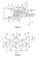
- FIG. 3 is a schematic perspective view showing the structure of the piezoelectric vibration piece 32
- FIG. 4 is a cross-sectional view cut along line F-F of FIG. 3 (a diagram showing only the cross-sectional plane).
- the piezoelectric vibration piece 32 is formed by processing crystal being a piezoelectric material to become a tuning-fork type.
- cutting from a single crystal is done in such a manner that the X axis of FIG. 3 will be an electrical axis, the Y axis will be a mechanical axis, and the Z axis will be an optical axis.
- an XY plane structured by the X and Y axes is formed by tilting about -5 to +5 degrees in a counterclockwise direction about the X axis.
- the piezoelectric vibration piece 32 is provided with a pair of vibration arms 34 and 35 horizontally extending from the base section 51 as described in the foregoing.
- the base section 51 of the piezoelectric vibration piece 32 includes, in the vicinity of the base end sections of the vibration arms 34 and 35, constriction sections or notch sections 48 and 48 formed by increasing or reducing the width of the base section 51. By including such notch sections 48 and 48, in the piezoelectric vibration piece 32, no vibration is transferred from the vibration arms 34 and 35 to the side of the base section 51.
- the vibration arms 34 and 35 are provided with grooves 44 and 44, respectively, extending in the length direction. These grooves 44 and 44 are, as shown in FIG. 4, formed on the surface and back sides of each vibration arm 34. Although not shown in FIG. 4, the grooves formed in the vibration arm 35 have the same structure. In FIG. 4, the total length from one end section M1 to the other end section M2 in the length direction of the groove 44 is denoted by LA.
- the extraction electrodes 33 and 33 for connection with the electrode sections 31 and 31 of the package 36.
- the extraction electrodes 33 and 33 are both provided on the surface side and the back side of the base section 51 of the piezoelectric vibration piece 32.
- Such extraction electrodes 33 and 33 are connected to excitation electrodes, not shown, provided in the grooves 44 and 44 of the vibration arms 34 and 35. The manner of providing such excitation electrodes is the same as the conventional, and thus is not described.
- the grooves 44 and 44 provided in the vibration arms 34 and 35 have the same structure in both vibration arms 34 and 35.
- any illustration is indicated in FIG. 3 and 4 shown, and the comprehensive relationship between the vibration arms and grooves is described, for example.
- the arm width W1 of the piezoelectric vibration piece 32 is, for example, in the range from 50 ⁇ m to 150 ⁇ m.
- the groove depth D2 of the groove 44 of FIG. 4 is so set as to be 30% or more but less than 50% of D1.
- the groove width W2 of the groove 44 is, preferably, so set as to be 40% or more of the arm width W1 of the vibration arm 35, and more preferably, 70% or more.
- the material structuring the vibration arm 34 (in this embodiment, “crystal material”) is separated into two parts of 34a and 34b by the groove 44 provided in the vibration arm 34.
- the bottom section 46 is formed to be a unit with arm 34.
- the groove 44 is a bottomed groove, and not going through.
- the grooves 44 and 44 of the vibration arms 34 and 35 are provided, respectively, with support sections 45 and 45 both of a sidebar type, for example.
- the support section 45 is connected to be a unit therewith.
- the support section 45 is formed to be a unit with the bottom section 46 of the groove 44, and the resulting unit sections 45a and 45b both being a unit with the groove bottom section 46 of the support section 45 are so formed as to be thicker than the thickness of the support section 45.
- the unit section 45a where the support section 45 and the bottom section 46 are united together to be a piece is extending towards the bottom section 46, looking like a bell-bottom.
- the groove 44 and the support section 45 have a one-to-one relationship, and the distance L1 from one end section M1 of the groove 44 to the center O of the support section 45 is equal to the distance L2 from the center O of the support section 45 to the other end section M2 of the groove 44.
- the total length LA of the groove 44 is divided into two by the support section 45, and when the piezoelectric vibration piece 32 is driven, the bending vibration is equally divided by the support section 45.
- deformation in the twisting direction is cancelled out, preventing twisting deformation as a whole.
- the vibration arm 34 is increased in strength, and the Cl (Crystal Impedance) value is also increased. Accordingly, in the allowance range for increase of the Cl value, by increasing the number of the support sections 45, the strength of the vibration arm 34 can be increased to a greater degree.
- the present embodiment is structured as above, and as shown in FIG. 4, the grooves 44 and 44 formed in the vibration arms 34 and 35, respectively, of the piezoelectric vibration piece 32 are both bottomed grooves. Thus, in comparison with a case of forming a through groove in both vibration arms 34 and 35, these vibration arms 34 and 35 are provided with the better strength.
- the grooves 44 are each provided with the support section 45.
- the support section 45 forms a unit with the bottom section 46 of the groove 44, the support section 45 supports the parts 34a and 34b structuring the vibration arm 34 separated by the groove 44 in the width direction so that deformation in the twisting direction is prevented from occurring. Accordingly, the vibration arm 34 can be enforced in strength in the twisting direction thereof.
- the support section 45 includes the unit sections 45a and 45b being thinner towards the bottom section 46 of the groove 44.
- the support section 45 is securely connected especially to the bottom section 46 of the groove 44. Accordingly, in the piezoelectric vibration piece 32, with the support section 45 being securely fixed to the bottom section 46 of the groove 44, the deformation force in the twisting direction of the vibration arm 34 is effectively dealt with. In such a manner, the deformation in the twisting direction can be prevented in a more effective manner.
- the arm width W1 of the vibration arms 34 and 35 of the piezoelectric vibration piece 32 is, for example, in the range from 50 ⁇ m to 150 ⁇ m.
- the groove depth D2 of the groove 44 is so set as to be 30% or more but less than 50% of the material thickness of the vibration arms 34 and 35. With such a structure, the Cl value can be low enough.
- the Cl value is about 100 k ⁇ being close to the limit of the practical range even if the groove depth is 30 ⁇ m (30% of the material thickness), and the groove width is 70 ⁇ m (70% of the arm width, and with this dimension, the Cl value is not reduced that much even if the groove width is widened more).
- the groove width W2 of the groove 44 of the piezoelectric vibration piece 32 is so set as to be 40% or more of the arm width W1 of the vibration arm. In this case, if the groove width W2 of the groove 44 is less than 40% of the arm width W1 of the vibration arm, the advantage of reduction of the Cl value cannot be sufficiently obtained, and thus the resulting Cl value cannot be practical.
- the Cl value is about 100 k ⁇ being close to the limit of the practical range even if the groove depth is 45 ⁇ m (45% of the material thickness, and increasing the groove depth more may go through the material, and is difficult to manufacture), and the groove width is 40 ⁇ m (40% of the arm width).
- the groove width W2 of the groove 44 can be 70% or more of the arm width W1 of the vibration arm. In this manner, the Cl value will be in the range of maximizing the reduction effects thereof.
- the groove width W2 of the groove 44 is 100% of the arm width W1 of the vibration arm, needless to say, this does not allow groove formation.
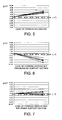
- FIGS. 5 and 7 are both graphs as a result of simulation of the relationship between the frequency change rate and the current based on the electric field applied to the piezoelectric vibration piece at the time of driving.
- k1 is a constant (becomes a positive value) that can be decided as an elastic body when the piezoelectric vibration piece vibrates in the horizontal direction.
- k2 is a constant (becomes a negative value) determined as an elastic body when the piezoelectric vibration piece vibrates in the vertical direction (z direction of FIG. 13).
- FIG. 5 shows the property of the piezoelectric vibration piece of a case where no groove is formed in the piezoelectric vibration piece, that is, for example, the grooves 44 and 44 are not provided to such a piezoelectric vibration piece 32 as shown in FIG. 3.
- ⁇ f/f denotes a positive value
- the vibration frequency varies in the range from 3 to 5 ppm.
- FIG. 6 shows the property of the piezoelectric vibration piece of a case where the piezoelectric vibration piece is formed only with a groove, that is, the piezoelectric vibration piece 32 of FIG. 3 is provided with the grooves 44 and 44 but not with the support sections 45 and 45, for example.
- the vertical vibration component expressed by k2 becomes larger, ⁇ f/f indicates a negative value, and the vibration frequency varies in the range from -8 to -4 ppm.
- FIG. 7 shows the property of the piezoelectric vibration piece 32 of the present embodiment, that is, of the piezoelectric vibration piece in which the vibration arms 34 and 35 are formed with the grooves 44 and 44, and the support section 45 is formed in the groove 44.
- the vertical vibration component expressed by k2 is considerably reduced, and the variation ratio of the vibration frequency being ⁇ f/f fits in the range from about -1 to +2.
- FIGS. 8 and 9 are both graphs showing the interrelation between the Cl value and the temperature property for the piezoelectric vibration piece of a so-called tuning-fork type, and shows the relationship between the change of the Cl value and the maximum temperature described by referring to FIGS. 14 and 15.
- FIG. 8 is a graph showing the Cl value - temperature property of a case where the vibration arm is formed with a groove but not with a support section
- FIG. 9 is a graph showing the Cl value - temperature property of the piezoelectric vibration piece 32 of the present embodiment.
- the reason why the interrelation is observed between the Cl value and the maximum temperature is that, when the vibration arm is formed with a groove but not with a support section, the vertical vibration component of the vibration arm becomes unstable. As shown in FIG. 9, if the vibration arm is formed with both a groove and a support section, the maximum temperature can be stable without depending on the Cl value as shown in FIG. 9.
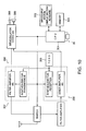
- FIG. 10 is a diagram showing the schematic structure of a portable digital phone unit as an example of the electric equipment using the piezoelectric device according to the above-described embodiment of the present invention.
- a microphone 308 for receiving the voice of a caller, and a speaker 309 for converting the received content into a voice output.
- a CPU (Central Processing Unit) 301 being an integrated circuit as a control section connected to a modulation and demodulation section for a transmission and reception signal is also included.
- the CPU 301 controls an information input/output section 302 structured by an LCD as an image display section, and operation keys and others for information input, and information storage means 303 structured by RAM, ROM, and others.
- the piezoelectric device 30 is connected, and the output frequency thereof is used as a clock signal matching the control details by a predetermined frequency divider (not shown) included in the CPU 301.
- the piezoelectric device 30 attached to the CPU 301 is not necessarily a single unit such as the piezoelectric device 30, but may be an oscillator as a result of combining the piezoelectric device 30 and the like, and any predetermined frequency divider and the like.
- the CPU 301 is connected to a temperature-compensated crystal oscillator (TCXO) 305, and the temperature-compensated crystal oscillator 305 is connected to both a transmission section 307 and a reception section 306.
- TXO temperature-compensated crystal oscillator
- the temperature-compensated crystal oscillator 305 is connected to both a transmission section 307 and a reception section 306.
- this invention is applicable to every piezoelectric device no matter what name they carry such as a piezoelectric vibrator, a piezoelectric oscillator, or the like as long as a piezoelectric vibration piece is accommodated in a package, or a metal tubular case.
- the package is in the shape of box made of a piezoelectric material.
- the present invention is applicable to the ones including any type of package or case as long as the package is partially light transmittable.
Landscapes
- Physics & Mathematics (AREA)
- Acoustics & Sound (AREA)
- Chemical & Material Sciences (AREA)
- Crystallography & Structural Chemistry (AREA)
- Piezo-Electric Or Mechanical Vibrators, Or Delay Or Filter Circuits (AREA)
- Telephone Set Structure (AREA)
- Apparatuses For Generation Of Mechanical Vibrations (AREA)
Applications Claiming Priority (3)
| Application Number | Priority Date | Filing Date | Title |
|---|---|---|---|
| JP2002365531 | 2002-12-17 | ||
| JP2002365531A JP4281348B2 (ja) | 2002-12-17 | 2002-12-17 | 圧電振動片と圧電振動片を利用した圧電デバイス、ならびに圧電デバイスを利用した携帯電話装置および圧電デバイスを利用した電子機器 |
| PCT/JP2003/016055 WO2004064252A1 (ja) | 2002-12-17 | 2003-12-15 | 圧電振動片と圧電振動片を利用した圧電デバイス、ならびに圧電デバイスを利用した携帯電話装置および圧電デバイスを利用した電子機器 |
Publications (2)
| Publication Number | Publication Date |
|---|---|
| EP1575166A1 true EP1575166A1 (de) | 2005-09-14 |
| EP1575166A4 EP1575166A4 (de) | 2006-05-10 |
Family
ID=32708100
Family Applications (1)
| Application Number | Title | Priority Date | Filing Date |
|---|---|---|---|
| EP03778933A Withdrawn EP1575166A4 (de) | 2002-12-17 | 2003-12-15 | Piezoelektrisches vibrationsstü ck und daspiezoelektrische vibrationsstück verwendende piezoelektrische einrichtung |
Country Status (7)
| Country | Link |
|---|---|
| US (1) | US7015630B2 (de) |
| EP (1) | EP1575166A4 (de) |
| JP (1) | JP4281348B2 (de) |
| KR (1) | KR100733170B1 (de) |
| CN (1) | CN100464499C (de) |
| TW (1) | TWI233257B (de) |
| WO (1) | WO2004064252A1 (de) |
Cited By (1)
| Publication number | Priority date | Publication date | Assignee | Title |
|---|---|---|---|---|
| US8766515B2 (en) | 2008-10-24 | 2014-07-01 | Seiko Epson Corporation | Flexural vibrating reed, flexural vibrator, and piezoelectric device |
Families Citing this family (74)
| Publication number | Priority date | Publication date | Assignee | Title |
|---|---|---|---|---|
| USD516500S1 (en) * | 2003-07-31 | 2006-03-07 | Seiko Epson Corporation | Piezo electric resonator |
| USD520940S1 (en) * | 2003-07-31 | 2006-05-16 | Seiko Epson Corporation | Piezo electric resonator |
| JP4141432B2 (ja) * | 2003-11-10 | 2008-08-27 | 日本電波工業株式会社 | 音叉型水晶振動子 |
| JP2006246448A (ja) * | 2005-02-02 | 2006-09-14 | Nippon Dempa Kogyo Co Ltd | 水晶振動子、水晶振動子パッケージ及び水晶発振器 |
| TW200633377A (en) | 2005-02-02 | 2006-09-16 | Nihon Dempa Kogyo Co | Piezo-electric vibrator |
| JP4638263B2 (ja) * | 2005-03-23 | 2011-02-23 | リバーエレテック株式会社 | 音叉型屈曲振動子 |
| US7084556B1 (en) * | 2005-06-09 | 2006-08-01 | Eta Sa Manufacture Horlogere Suisse | Small-sized piezoelectric resonator |
| US7138752B1 (en) * | 2005-06-09 | 2006-11-21 | Eta Sa Manufacture Horlogere Suisse | Small-sized piezoelectric resonator |
| US20060279176A1 (en) * | 2005-06-09 | 2006-12-14 | Eta Manufacture Horlogere Suisse | Small-sized piezoelectric resonator |
| US7694734B2 (en) * | 2005-10-31 | 2010-04-13 | Baker Hughes Incorporated | Method and apparatus for insulating a resonator downhole |
| JP4404218B2 (ja) * | 2006-03-29 | 2010-01-27 | セイコーエプソン株式会社 | 音叉振動子およびその製造方法 |
| JP2007274610A (ja) * | 2006-03-31 | 2007-10-18 | Nippon Dempa Kogyo Co Ltd | 水晶振動子及び水晶振動子パッケージ |
| US7863803B2 (en) | 2007-05-30 | 2011-01-04 | Epson Toyocom Corporation | Tuning fork resonator element and tuning fork resonator |
| JP5076657B2 (ja) * | 2007-06-11 | 2012-11-21 | セイコーエプソン株式会社 | 応力感応型センサ用の双音叉型振動素子及び加速度検知ユニット |
| JP4509152B2 (ja) * | 2007-08-28 | 2010-07-21 | シャープ株式会社 | 薄膜圧電トランスおよびその製造方法 |
| JP4453763B2 (ja) * | 2007-10-19 | 2010-04-21 | セイコーエプソン株式会社 | 電子部品とその実装構造及び実装方法 |
| JP4539708B2 (ja) | 2007-11-02 | 2010-09-08 | エプソントヨコム株式会社 | 圧電振動片、圧電振動子および加速度センサ |
| US8446079B2 (en) * | 2008-05-23 | 2013-05-21 | Statek Corporation | Piezoelectric resonator with vibration isolation |
| JP5446187B2 (ja) * | 2008-09-17 | 2014-03-19 | セイコーエプソン株式会社 | 振動片および振動型センサ |
| JP5155275B2 (ja) * | 2008-10-16 | 2013-03-06 | 日本電波工業株式会社 | 音叉型圧電振動片、圧電フレーム及び圧電デバイス |
| US8067880B2 (en) * | 2008-12-27 | 2011-11-29 | Seiko Epson Corporation | Flexural vibration element and electronic component |
| JP2010233339A (ja) * | 2009-03-26 | 2010-10-14 | Seiko Epson Corp | 圧電モーター、液体噴射装置及び時計 |
| JP5272880B2 (ja) * | 2009-04-30 | 2013-08-28 | セイコーエプソン株式会社 | 屈曲振動片 |
| JP2011082945A (ja) * | 2009-09-08 | 2011-04-21 | Seiko Epson Corp | 屈曲振動片、屈曲振動子、および電子デバイス |
| JP5482541B2 (ja) * | 2009-10-01 | 2014-05-07 | セイコーエプソン株式会社 | 振動片、振動子、発振器、及び電子機器 |
| JP5565163B2 (ja) * | 2009-10-08 | 2014-08-06 | セイコーエプソン株式会社 | 振動片、振動子、発振器、および電子機器 |
| USD646236S1 (en) * | 2009-11-05 | 2011-10-04 | Seiko Instruments Inc. | Quartz crystal |
| USD634287S1 (en) * | 2009-11-06 | 2011-03-15 | Seiko Instruments Inc. | Quartz crystal |
| USD643383S1 (en) * | 2009-11-06 | 2011-08-16 | Seiko Instruments Inc. | Quartz crystal |
| USD653631S1 (en) * | 2009-11-06 | 2012-02-07 | Seiko Instruments Inc. | Quartz crystal |
| USD643385S1 (en) * | 2009-11-06 | 2011-08-16 | Seiko Instruments Inc. | Quartz crystal |
| USD643382S1 (en) * | 2009-11-06 | 2011-08-16 | Seiko Instruments Inc. | Quartz crystal |
| CN103199817B (zh) * | 2009-12-02 | 2015-11-18 | 威华微机电股份有限公司 | 音叉型石英晶体谐振器 |
| US20110215680A1 (en) * | 2010-03-05 | 2011-09-08 | Seiko Epson Corporation | Resonator element, resonator, oscillator, and electronic device |
| JP5633319B2 (ja) * | 2010-03-17 | 2014-12-03 | セイコーエプソン株式会社 | 振動片、センサー素子、センサーおよび電子機器 |
| US20110227450A1 (en) * | 2010-03-18 | 2011-09-22 | Seiko Epson Corporation | Resonator body, resonator device, and electronic device |
| JP5003783B2 (ja) * | 2010-03-26 | 2012-08-15 | セイコーエプソン株式会社 | 圧電振動片、圧電振動子および加速度センサ |
| JP5003782B2 (ja) * | 2010-03-26 | 2012-08-15 | セイコーエプソン株式会社 | 圧電振動片、圧電振動子および加速度センサ |
| USD643384S1 (en) * | 2010-03-29 | 2011-08-16 | Seiko Instruments Inc. | Quartz crystal |
| USD643387S1 (en) * | 2010-03-29 | 2011-08-16 | Seiko Instruments Inc. | Quartz crystal |
| USD653632S1 (en) * | 2010-03-29 | 2012-02-07 | Seiko Instruments Inc. | Quartz crystal |
| USD634288S1 (en) * | 2010-03-29 | 2011-03-15 | Seiko Instruments Inc. | Quartz crystal |
| USD646237S1 (en) * | 2010-03-29 | 2011-10-04 | Seiko Instruments Inc. | Quartz crystal |
| USD643386S1 (en) * | 2010-03-29 | 2011-08-16 | Seiko Instruments Inc. | Quartz crystal |
| JP5499852B2 (ja) * | 2010-04-08 | 2014-05-21 | セイコーエプソン株式会社 | 振動片、振動子 |
| JP2011259120A (ja) * | 2010-06-08 | 2011-12-22 | Seiko Epson Corp | 振動片、周波数調整方法、振動子、振動デバイス、および電子機器 |
| USD646655S1 (en) * | 2010-06-16 | 2011-10-11 | Seiko Instruments Inc. | Quartz crystal |
| USD646649S1 (en) * | 2010-06-16 | 2011-10-11 | Seiko Instruments Inc. | Quartz crystal |
| USD646648S1 (en) * | 2010-06-16 | 2011-10-11 | Seiko Instruments Inc. | Quartz crystal |
| USD637982S1 (en) * | 2010-06-16 | 2011-05-17 | Seiko Instruments Inc. | Quartz crystal |
| USD646652S1 (en) * | 2010-06-16 | 2011-10-11 | Seiko Instruments Inc. | Quartz crystal |
| USD648288S1 (en) * | 2010-06-16 | 2011-11-08 | Seiko Instruments Inc. | Quartz crystal |
| USD646651S1 (en) * | 2010-06-16 | 2011-10-11 | Seiko Instruments Inc. | Quartz crystal |
| USD646654S1 (en) * | 2010-06-16 | 2011-10-11 | Seiko Instruments Inc. | Quartz crystal |
| USD646656S1 (en) * | 2010-06-16 | 2011-10-11 | Seiko Instruments Inc. | Quartz crystal |
| USD647071S1 (en) * | 2010-06-16 | 2011-10-18 | Seiko Instruments Inc. | Quartz crystal |
| USD646650S1 (en) * | 2010-06-16 | 2011-10-11 | Seiko Instruments Inc. | Quartz crystal |
| USD646653S1 (en) * | 2010-06-16 | 2011-10-11 | Seiko Instruments Inc. | Quartz crystal |
| JP5080616B2 (ja) * | 2010-06-28 | 2012-11-21 | 日本電波工業株式会社 | 音叉型圧電振動片及び圧電デバイス |
| JP2012029262A (ja) * | 2010-07-28 | 2012-02-09 | Seiko Epson Corp | 圧電振動片及びその製造方法 |
| JP5003811B2 (ja) * | 2010-11-04 | 2012-08-15 | セイコーエプソン株式会社 | 圧電振動片、圧電振動子および加速度センサ |
| TW201242246A (en) * | 2011-02-25 | 2012-10-16 | Seiko Epson Corp | Piezoelectric vibration element, piezoelectric vibrator, piezoelectric oscillator, vibration gyro element, vibration gyro sensor, and electronic apparatus |
| KR101883004B1 (ko) * | 2011-12-22 | 2018-07-30 | 삼성전기주식회사 | 압전 진동편 및 압전 진동편을 이용한 압전 디바이스 |
| JPWO2014002892A1 (ja) * | 2012-06-27 | 2016-05-30 | 株式会社村田製作所 | 音叉型水晶振動子 |
| JP6200636B2 (ja) * | 2012-07-26 | 2017-09-20 | エスアイアイ・クリスタルテクノロジー株式会社 | 圧電振動片、圧電振動子、発振器、電子機器、及び電波時計 |
| US9464951B2 (en) * | 2013-10-16 | 2016-10-11 | Sercel Inc. | Method and apparatus for electrical gap setting for a piezoelectric pressure sensor |
| JP2015097366A (ja) * | 2013-11-16 | 2015-05-21 | セイコーエプソン株式会社 | 振動素子、振動子、発振器、電子機器および移動体 |
| JP2016065752A (ja) * | 2014-09-24 | 2016-04-28 | セイコーエプソン株式会社 | 振動片、角速度センサー、電子機器および移動体 |
| JP2016146595A (ja) * | 2015-02-09 | 2016-08-12 | セイコーエプソン株式会社 | 振動片の製造方法、ウェハー、振動片、振動子、発振器、リアルタイムクロック、電子機器、および移動体 |
| JP6479509B2 (ja) * | 2015-03-09 | 2019-03-06 | シチズン時計株式会社 | 圧電振動子 |
| JP6582501B2 (ja) * | 2015-04-02 | 2019-10-02 | セイコーエプソン株式会社 | 振動素子、振動子、電子機器および移動体 |
| JP7026444B2 (ja) * | 2017-03-06 | 2022-02-28 | エスアイアイ・クリスタルテクノロジー株式会社 | 圧電振動片の製造方法 |
| EP3468036A1 (de) * | 2017-10-03 | 2019-04-10 | Micro Crystal AG | Piezoelektrischer resonator kleiner grösse |
| CN113331912B (zh) * | 2021-07-20 | 2022-09-06 | 昆明理工大学 | 一种用于脑血栓清除的振动执行器以及血栓清除设备 |
Family Cites Families (9)
| Publication number | Priority date | Publication date | Assignee | Title |
|---|---|---|---|---|
| JPS5252597A (en) * | 1975-10-27 | 1977-04-27 | Citizen Watch Co Ltd | Bend type piezoelectric vibrator |
| JPS5689117A (en) * | 1979-12-20 | 1981-07-20 | Seiko Instr & Electronics Ltd | Tuning fork type piezo-oscillator |
| JPS5694813A (en) * | 1979-12-27 | 1981-07-31 | Seiko Instr & Electronics Ltd | Tuning fork type piezoelectric oscillator |
| EP1788702A3 (de) * | 2000-12-25 | 2008-01-16 | Seiko Epson Corporation | Schwingelement, Vibrator, Oszillator und elektronisches Gerät |
| JP2002261575A (ja) * | 2000-12-25 | 2002-09-13 | Seiko Epson Corp | 振動片、振動子、発振器及び電子機器 |
| JP3900846B2 (ja) * | 2001-03-02 | 2007-04-04 | セイコーエプソン株式会社 | 音叉型水晶振動片、振動子、発振器及び携帯用電話装置 |
| JP2003092530A (ja) * | 2001-09-17 | 2003-03-28 | Seiko Epson Corp | 音叉型振動片、音叉型振動子、音叉型発振器及び電子機器 |
| US6791243B2 (en) * | 2002-03-06 | 2004-09-14 | Piedek Technical Laboratory | Quartz crystal unit and its manufacturing method |
| JP4001029B2 (ja) * | 2002-03-25 | 2007-10-31 | セイコーエプソン株式会社 | 音叉型圧電振動片及びその製造方法、圧電デバイス |
-
2002
- 2002-12-17 JP JP2002365531A patent/JP4281348B2/ja not_active Expired - Fee Related
-
2003
- 2003-12-15 EP EP03778933A patent/EP1575166A4/de not_active Withdrawn
- 2003-12-15 US US10/735,860 patent/US7015630B2/en not_active Expired - Lifetime
- 2003-12-15 WO PCT/JP2003/016055 patent/WO2004064252A1/ja not_active Ceased
- 2003-12-15 KR KR1020057008812A patent/KR100733170B1/ko not_active Expired - Fee Related
- 2003-12-15 CN CNB2003801034594A patent/CN100464499C/zh not_active Expired - Fee Related
- 2003-12-16 TW TW092135605A patent/TWI233257B/zh not_active IP Right Cessation
Non-Patent Citations (2)
| Title |
|---|
| No further relevant documents disclosed * |
| See also references of WO2004064252A1 * |
Cited By (1)
| Publication number | Priority date | Publication date | Assignee | Title |
|---|---|---|---|---|
| US8766515B2 (en) | 2008-10-24 | 2014-07-01 | Seiko Epson Corporation | Flexural vibrating reed, flexural vibrator, and piezoelectric device |
Also Published As
| Publication number | Publication date |
|---|---|
| US20050040737A1 (en) | 2005-02-24 |
| EP1575166A4 (de) | 2006-05-10 |
| CN100464499C (zh) | 2009-02-25 |
| JP4281348B2 (ja) | 2009-06-17 |
| US7015630B2 (en) | 2006-03-21 |
| TW200428770A (en) | 2004-12-16 |
| CN1711680A (zh) | 2005-12-21 |
| KR100733170B1 (ko) | 2008-01-07 |
| WO2004064252A1 (ja) | 2004-07-29 |
| JP2004200917A (ja) | 2004-07-15 |
| TWI233257B (en) | 2005-05-21 |
| KR20050086686A (en) | 2005-08-30 |
Similar Documents
| Publication | Publication Date | Title |
|---|---|---|
| EP1575166A1 (de) | Piezoelektrisches vibrationsst ck und daspiezoelektrische vibrationsst ck verwendende piezoelektrische einrichtung | |
| US7067966B2 (en) | Piezoelectric device, cellular phone system using the piezoelectric device, and electronic equipment using the piezoelectric device | |
| US8692632B2 (en) | Resonator element, resonator, oscillator, and electronic device | |
| CN104009730B (zh) | 振动片、振子、振荡器、传感器以及电子设备 | |
| CN102142827A (zh) | 振动体、振动装置以及电子设备 | |
| US20020121175A1 (en) | Vibrating reed, vibrator, oscillator and electronic device | |
| CN109478876A (zh) | 谐振器和谐振装置 | |
| JP2014090290A (ja) | 振動片、振動デバイス、電子機器及び移動体 | |
| CN104038178A (zh) | 振动元件、振子、振荡器、电子设备及移动体 | |
| JP2013062643A (ja) | 振動片、振動子、発振器及び電子機器 | |
| CN102195610A (zh) | 振动片、压电装置、以及电子设备 | |
| US11233497B2 (en) | Piezoelectric vibrator | |
| US20230261635A1 (en) | Piezoelectric vibration element, piezoelectric vibrator, and piezoelectric oscillator | |
| JP3975927B2 (ja) | 圧電振動片と圧電振動片を利用した圧電デバイス、ならびに圧電デバイスを利用した携帯電話装置および圧電デバイスを利用した電子機器 | |
| CN104660169A (zh) | 振动元件、振子、振荡器、电子设备及移动体 | |
| CN113302838B (zh) | 振动元件、振子以及振动元件的制造方法 | |
| JP4020031B2 (ja) | 圧電振動片と圧電振動片を利用した圧電デバイス、ならびに圧電デバイスを利用した携帯電話装置および圧電デバイスを利用した電子機器 | |
| JP4020010B2 (ja) | 圧電振動片と圧電振動片を利用した圧電デバイス、ならびに圧電デバイスを利用した携帯電話装置および圧電デバイスを利用した電子機器 | |
| JP2012142666A (ja) | 振動デバイスおよび電子機器 | |
| US20250183872A1 (en) | Piezoelectric vibration element | |
| US20240297636A1 (en) | Resonator Element And Resonator Device | |
| US20240297637A1 (en) | Resonator Device | |
| US20250357913A1 (en) | Quartz vibrating element and quartz vibrator including the same | |
| JP2003229448A (ja) | 半導体素子の電極構造とそれを用いた圧電発振器 | |
| US20230006124A1 (en) | Crystal element, crystal device, electronic equipment, and method for manufacturing crystal element |
Legal Events
| Date | Code | Title | Description |
|---|---|---|---|
| PUAI | Public reference made under article 153(3) epc to a published international application that has entered the european phase |
Free format text: ORIGINAL CODE: 0009012 |
|
| 17P | Request for examination filed |
Effective date: 20050517 |
|
| AK | Designated contracting states |
Kind code of ref document: A1 Designated state(s): AT BE BG CH CY CZ DE DK EE ES FI FR GB GR HU IE IT LI LU MC NL PT SE SI SK TR |
|
| RTI1 | Title (correction) |
Free format text: PIEZOELECTRIC VIBRATION PIECE AND PIEZOELECTRIC DEVICE USING PIEZOELECTRIC VIBRATION PIECE, PORTABLE PHONE DEVICE USING P |
|
| RBV | Designated contracting states (corrected) |
Designated state(s): CH DE FR GB LI |
|
| A4 | Supplementary search report drawn up and despatched |
Effective date: 20060329 |
|
| 17Q | First examination report despatched |
Effective date: 20071127 |
|
| RIC1 | Information provided on ipc code assigned before grant |
Ipc: H03H 9/21 20060101AFI20150630BHEP |
|
| GRAP | Despatch of communication of intention to grant a patent |
Free format text: ORIGINAL CODE: EPIDOSNIGR1 |
|
| INTG | Intention to grant announced |
Effective date: 20151105 |
|
| STAA | Information on the status of an ep patent application or granted ep patent |
Free format text: STATUS: THE APPLICATION IS DEEMED TO BE WITHDRAWN |
|
| 18D | Application deemed to be withdrawn |
Effective date: 20160316 |