EP1575046A2 - Fehlerkorrektionskreis - Google Patents
Fehlerkorrektionskreis Download PDFInfo
- Publication number
- EP1575046A2 EP1575046A2 EP04019951A EP04019951A EP1575046A2 EP 1575046 A2 EP1575046 A2 EP 1575046A2 EP 04019951 A EP04019951 A EP 04019951A EP 04019951 A EP04019951 A EP 04019951A EP 1575046 A2 EP1575046 A2 EP 1575046A2
- Authority
- EP
- European Patent Office
- Prior art keywords
- signal
- error
- rotational speed
- sinusoidal
- recordable disk
- Prior art date
- Legal status (The legal status is an assumption and is not a legal conclusion. Google has not performed a legal analysis and makes no representation as to the accuracy of the status listed.)
- Withdrawn
Links
Images


Classifications
-
- G—PHYSICS
- G11—INFORMATION STORAGE
- G11B—INFORMATION STORAGE BASED ON RELATIVE MOVEMENT BETWEEN RECORD CARRIER AND TRANSDUCER
- G11B19/00—Driving, starting, stopping record carriers not specifically of filamentary or web form, or of supports therefor; Control thereof; Control of operating function ; Driving both disc and head
- G11B19/20—Driving; Starting; Stopping; Control thereof
- G11B19/28—Speed controlling, regulating, or indicating
-
- F—MECHANICAL ENGINEERING; LIGHTING; HEATING; WEAPONS; BLASTING
- F16—ENGINEERING ELEMENTS AND UNITS; GENERAL MEASURES FOR PRODUCING AND MAINTAINING EFFECTIVE FUNCTIONING OF MACHINES OR INSTALLATIONS; THERMAL INSULATION IN GENERAL
- F16L—PIPES; JOINTS OR FITTINGS FOR PIPES; SUPPORTS FOR PIPES, CABLES OR PROTECTIVE TUBING; MEANS FOR THERMAL INSULATION IN GENERAL
- F16L33/00—Arrangements for connecting hoses to rigid members; Rigid hose-connectors, i.e. single members engaging both hoses
- F16L33/22—Arrangements for connecting hoses to rigid members; Rigid hose-connectors, i.e. single members engaging both hoses with means not mentioned in the preceding groups for gripping the hose between inner and outer parts
- F16L33/228—Arrangements for connecting hoses to rigid members; Rigid hose-connectors, i.e. single members engaging both hoses with means not mentioned in the preceding groups for gripping the hose between inner and outer parts a flexible wire being coiled upon the hose
-
- F—MECHANICAL ENGINEERING; LIGHTING; HEATING; WEAPONS; BLASTING
- F16—ENGINEERING ELEMENTS AND UNITS; GENERAL MEASURES FOR PRODUCING AND MAINTAINING EFFECTIVE FUNCTIONING OF MACHINES OR INSTALLATIONS; THERMAL INSULATION IN GENERAL
- F16L—PIPES; JOINTS OR FITTINGS FOR PIPES; SUPPORTS FOR PIPES, CABLES OR PROTECTIVE TUBING; MEANS FOR THERMAL INSULATION IN GENERAL
- F16L33/00—Arrangements for connecting hoses to rigid members; Rigid hose-connectors, i.e. single members engaging both hoses
- F16L33/20—Undivided rings, sleeves, or like members contracted on the hose or expanded inside the hose by means of tools; Arrangements using such members
- F16L33/213—Undivided rings, sleeves, or like members contracted on the hose or expanded inside the hose by means of tools; Arrangements using such members only a sleeve being expanded inside the hose
Definitions
- Some disk drive devices for computer systems have a recordable disk driven by a spindle motor. To conduct read and write operations, the recordable disk is rotated at a predetermined rotational speed, and a reading or writing element reads or writes information to or from the recordable disk. To determine, monitor, and adjust the speed of the recordable disk, these disk drives may utilize an encoder wheel configured to rotate at the same speed as the recordable disk.
- the encoder wheel may be a disk-shaped device that includes a series of reflective and non-reflective regions alternatively disposed circumferentially around the encoder wheel.
- a directed light source shines light on the encoder wheel as it rotates with the recordable disk. When the light shines on the reflective regions, a relatively great amount of the light is reflected back to a photodetector. Conversely, when the light shines on the non-reflective regions, a relatively low amount of light (if any) is reflected back to the photodetector.
- the actual rotational speed of the encoder wheel can be determined by measuring the elapsed time of reflective and non-reflective regions of the encoder wheel, respectively, passing by the photodetector. Because the encoder wheel is configured to rotate at the same speed as the recordable disk, it is assumed that the determined rotational speed of the decoder is the same as the actual rotational speed of the recordable disk.
- the determined rotational speed of the decoder can be compared to a predetermined desired rotational speed of the recordable disk, and, if they differ, the spindle motor can be controlled to adjust the actual rotational speed of the recordable disk upward or downward, as appropriate, to match the predetermined desired speed of the recordable disk.
- Figure 1 is a schematic view of a first embodiment of a disk drive
- Figure 1 A is a schematic view of a second embodiment of a disk drive
- Figure 2 is a schematic view of a disk drive according to an embodiment
- Figure 3 is a schematic view of a disk drive according to an embodiment
- Figure 4 is a schematic view of a disk drive according to an embodiment.
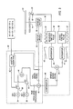
- Figure 5 is a schematic view of a control circuit for a disk drive according to an embodiment.
- An adaptive feedforward circuit that corrects the unintended effects of a misalignment of the center of the disk-shaped encoder wheel relative to the center of the recordable disk in a disk drive assembly.
- the adaptive feedforward circuit accomplishes this correction by incorporating a true oscillation error signal into the system.
- a true oscillation error signal is a signal input into the system that cancels out a falsely-read error signal such as that caused by, for example, misalignment of the encoder wheel relative to the recordable disk.
- the true oscillation error signal provides an opposite oscillation signal to the signal generated by the misalignment of the encoder wheel, which cancels the effects of this misalignment.
- the true oscillation error signal is generated by using a numerical methods analysis to converge the true oscillation error signal to a value that is equal and opposite to the oscillation signal created by the misalignment of the encoder wheel. Therefore, the system properly determines the difference between the actual rotational speed of the recordable disk and the desired rotational speed of the recordable disk, without experiencing the unintended effects of the misalignment.
- the adaptive feedforward circuit helps to provide a more robust system for maintaining a constant rotational speed of the recordable disk.
- a disk drive 10 is shown according to an embodiment.
- the general construction of the disk drive 10 includes recordable disk 12 coupled to spindle motor 18 by spindle shaft 16.
- the spindle motor 18 provides rotational energy to the recordable disk 12 to rotate the recordable disk 12 for reading and writing computer operations, as will generally be understood by one skilled in the art.
- Encoder wheel 14 may be a disk-shaped device configured to rotate at the same rate of speed as the recordable disk 12.
- Encoder wheel 14 is shown in Figure 1 as a separate and distinct disk that is attached to spindle shaft 16 so that it rotates at the same speed as recordable disk 12.
- the encoder wheel 14 includes a plurality of reflective regions 26 and non-reflective regions 28.
- the reflective regions 26 are constructed to reflect light while the non-reflective regions are constructed so that light does not reflect, or, alternatively, so that the amount of reflection is limited.
- Light source 20 (see Figure 1) is positioned to project light at the encoder wheel 14 such that it traces out light path 30 (as shown in Figure 2) across reflective regions 26 and non-reflective regions 28.
- photodetector 22 is positioned to receive light that is reflected back from the encoder wheel 14. As will be generally understood from Figures 1 and 2, the photodetector 22 will receive light from the encoder wheel 14 when the light source 20 projects light onto the reflective regions 26, but will receive a relatively small amount of reflected light (approaching no reflected light) when the light source 20 projects light onto the non-reflective regions 28. The photodetector 22 provides a signal to control circuit 24 indicative of the amount of reflected light detected.
- control circuit 24 Based on the photodetector signal, control circuit 24 generates a feed-back voltage signal to the spindle motor 18, as will be described in greater detail hereinafter, which is used to adjust the speed of the recordable disk 12 so that it rotates at the desired rotational speed.
- encoder wheel 14 may be attached directly to or made integral with recordable disk 12, as shown in Figure 1 A (where like elements have like references relative to Figure 1).
- the reflective and non-reflective regions 26 and 28 may be screen-printed onto surface of the recordable disk 12 or they may be embossed into the plastic surfaces of the recordable disk, for example.
- Other methods and configurations for causing the encoder wheel 14 rotate at the same speed as the recordable disk 12 will be known to those skilled in the art.
- the speed of rotation of the encoder wheel 14, and therefore the recordable disk 12 can be determined by measuring the amount of time that the photodetector 22 receives reflected light and the amount of time that the photodetector 22 does not receive reflected light.
- the photodetector signal is compared to one or more reference values to determine if the light source is shining on a reflective region or a non-reflective region of the encoder wheel 14.
- the photodetector signal is indicative of an amount of reflected light that falls below a reference value, then it may be determined that the light source is shining on a non-reflective region, whereas, if the photodetector signal is indicative of an amount of reflected light that is greater than a reference value (which may be different from the first reference value), then it may be determined that the light source is shining on a reflective region.
- the photodetector 22 may be configured to provide a binary "present” or "absent” signal indicating the presence or absence of received light.
- the amount of time that photodetector 22 detects the light path 30 across the reflective region 26 can be used to calculate the rotational speed of the encoder wheel 14 and therefore the recordable disk 12 by simple physics.
- the rotational speed of the encoder wheel 14 and therefore the recordable disk 12 can be determined. The methods for determining such rotational speed will be readily understood by one skilled in the art.
- Figure 3 a situation is shown where the encoder wheel 14 is attached to spindle 13 such that the encoder wheel 14 has a different center of rotation than the recordable disk 12. If the encoder wheel 14 is directly attached to or integral with recordable disk 12 (as shown in Figure 1A), then the respective centers of rotation may be misaligned when the encoder wheel 14 is attached or applied to the recordable disk 12. In any event, as shown in Figure 3, recordable disk 12 has a center of rotation 13 while encoder wheel 14 has an off-center of rotation 15, which causes the encoder wheel 14 to sinusoidally oscillate with respect to light source 20 and photodetector 22.
- the encoder wheel 14 when the encoder wheel 14 is at an arbitrary zero degree position of rotation, the light path along any one of the reflective regions 26 or non-reflective regions 28 (for purposes of example, reflective regions 26 is used in Figure 4) is shown as light path 30.
- the off-center axis 15 moves the encoder wheel 14 such that the light path is shown as light path 30a.
- the light path 30 shifts from 30 to 30a, which is a total distance of D1. Therefore, the total distance the reflective regions 26 must move is longer (distance of D3) when the encoder wheel 14 is at the zero degree position, as opposed to when it is at the 180 degree position (D2).
- the present embodiment injects a true oscillation error signal into an error correction mechanism of the control circuit 24.
- This true oscillation error signal is opposite of the error caused misalignment of the encoder wheel 14 to thereby cancel the effects of the off-center positioning of the encoder wheel 14.
- This true oscillation error signal is the sum of a sine and cosine wave at the frequencies of the speed of rotation of the disk as follows:
- A1 is a sine Fourier coefficient and B1 is a cosine Fourier coefficient.
- QS1 and QC1 are the signals generated by sine and cosine generators respectively.
- QS1 and QC1 could be generated by using the same sine or cosine function and shifting the respective phases so that QS1 and QC1 (whether generated from sine or cosine functions) are 90 degrees out of phase with each other.
- the signals generated by the sine and cosine generators merely represent un-scaled sinusoidal signals.
- the Fourier coefficients are used in conjunction with the signals from the sine and cosine generators QS1 and QC1 to provide an oscillation signal having specific desired characteristics according to the Fourier coefficients as will readily be understood by one skilled in the art.
- the Fourier coefficients are chosen such that the true oscillation error signal will cancel out the unintended oscillation signal caused by misalignment of the encoder wheel 14. The process for arriving at the correct Fourier coefficients will be discussed in greater detail below.
- control circuit 24 for driving the spindle motor 18 to compensate for the difference between disk center 13 and encoder center 15, as well as ensuring that the spindle motor 18 rotates the recordable disk 12 at the desired rotational speed is described in greater detail.
- the control circuit 24 generally includes actual error calculation portion 80 and sinusoidal error correction portion 84.
- Error calculation portion 80 determines the difference between the desired rotational speed of recordable disk 12 and the actual speed at which it is rotated. To accomplish this determination, error calculation portion 80 includes a target time per pulse block 56 and an integrator 54.
- the target time of the target time per pulse block 56 represents the desired time that should pass between one rising edge of an encoder output and when the next rising edge occurs. A rising edge is when a reflective portion of the encoder wheel comes into view of the photodetector 22 or when a non-reflective portion of the encoder wheel exits from view.
- the actual time between rising edges is measured by the measured time per pulse block 52 as each pulse arrives from the photodetector 22.
- the pulses from the measured time per pulse block 52 and target time per pulse block 56 are represented by waves 57 and 61.
- the actual time between encoder wheel pulses is integrated by integrator 50, and the target time is integrated by integrator 54 to accumulate total elapsed times.
- the total elapsed times are with respect to a reference angle of the disk, called the 0 degree angle. At the 0 degree angle point of rotation, both the ideal and actual total elapsed times are zeroed and the integration begins again.
- the accumulated results output from integrators 50 and 54 increases by the amount of time that has elapsed since the last pulse, as is the case in the measured time per pulse path, or the target time per pulse path. This accumulation increases steadily until it is zeroed at the 0 degree angle position.
- the accumulated times appear as sawtooth forms or built waves 63 or 59, whose frequency is that of the spindle rotating one revolution or 360 degrees once-around.
- the summing device 90 subtracts the built wave 63 from the built wave 59 to arrive at a spindle error signal, which represents the difference between the desired rotational speed and the actual rotational speed of the recordable disk.
- the spindle error signal is fed to a compensator 48 which can be any closed loop compensator such as a Proportional Integral Differentail (PID) or phase lead compensator, as will be readily understood by one skilled of the art.
- PID Proportional Integral Differentail
- the spindle error signal represents the difference between the actual disk rotation determined by the photodetector 22, and the measured time per pulse block 52 and the desired disk rotation as generated by target time per pulse block 56. This value, however, does not compensate for the unintended sinusoidal offset created by the distance between disk center 13 and encoder wheel center 15.
- Equation 1 (described above for calculating the true oscillation error signal) is used by sinusoidal error correction circuit 84 to create a total error signal.
- sine generator 34 generates a sine wave to provide QS1 in Equation 1.
- Cosine generator 36 similarly generates a cosine wave to provide QC1 in Equation 1.
- Summing device 46 causes the output of summation device 44 to be subtracted from the spindle error signal (after it passes through compensator 48). The result is a total error signal, which is provided to the motor driver 58.
- the motor driver 58 converts this signal into a voltage, such as through a digital to analog converter DAC (not shown), to drive the spindle motor 18 at the desired speed to obtain the desired rotational speed of the recordable disk 12. It should be noted, however, that the output of the summation device 44 can be subtracted from the spindle error signal before it passes through the compensator 48. In such an instance, the compensator 48 would be located along the total error signal in figure 5.
- the Fourier coefficients A1 and B1 are provided by the adapter algorithm 42, which uses an adaptive algorithm to arrive at the correct values for the Fourier coefficients A1 and B1 as will be discussed in greater detail below. Theoretically, if the Fourier coefficients A1 and B1 are correctly chosen, the resulting true oscillation error signal of Equation 1 will cancel the sinusoidal error arising from misalignment of the encoder wheel 14. To obtain the correct Fourier coefficients, an adaptive algorithm is applied in conjunction with equation 1 to arrive at the correct Fourier coefficients A1 and B1.
- the adaptive algorithm is used to arrive at the correct Fourier coefficients.
- the adaptive algorithm is used to converge initial Fourier coefficients A1 and B1 and therefore an initial true oscillation error signal from initial arbitrary starting values to end values.
- the starting values of the Fourier coefficients are any arbitrary values that do not necessarily cancel the effects of the off-center attachment of the encoder wheel 14.
- the end value after the adaptive algorithm has been completed provides an equation for generating a signal that is opposite of the unintended oscillation frequency generated by the misalignment of the encoder wheel 14.
- This adaptive algorithm may be similar to the LMS (least mean squared) algorithm, which is well known to those familiar with the art. and use a feedback mechanism to arrive at values for A1 and B1.
- the present embodiments utilize this adaptive algorithm to arrive at Fourier coefficients that combine with the signals provided by the sine and cosine generators 34 and 36 to result in an oscillation signal that is opposite to the oscillation signal created by the misalignment of the encoder wheel 14.
- the Fourier coefficients A1 and B1 converge on the correct values that cause Equation 1 to generate an oscillation signal that is equal and opposite to the unintended oscillation signal caused by the misalignment of the encoder wheel 14.
- Equation 2 and 3 The total error signal is substituted for Ek in Equations 2 and 3 as a feedback signal.
- Ek is multiplied by the adaptation coefficient u, which for example can be .25, and is then multiplied by the cosine and sine signals from the generators 34 and 36 as described above, and these results are then added to the Fourier coefficients A1 and B1.
- This process produces improved Fourier coefficients which yields a new true oscillation error signal for summing with the summation device 44 to generate a new total error signal.
- Equations 2 and 3 converge on values for the Fourier coefficients A1 and B1 that yield the true oscillation error signal of Equation 1 that is sufficient to offset the unintended error signal caused by the misalignment.
- A1 and B1 can be initialized to 0, and, with sufficient iterations, A1 and B1 will converge to values that cause cancellation of the misalignment error that is embedded in the spindle error signal, thus preventing this unintended error from causing the rotational speed of the recordable disk to vary sinusoidally.
Landscapes
- Engineering & Computer Science (AREA)
- General Engineering & Computer Science (AREA)
- Mechanical Engineering (AREA)
- Rotational Drive Of Disk (AREA)
- Optical Transform (AREA)
- Control Of Electric Motors In General (AREA)
Applications Claiming Priority (2)
| Application Number | Priority Date | Filing Date | Title |
|---|---|---|---|
| US796228 | 2004-03-09 | ||
| US10/796,228 US7330326B2 (en) | 2004-03-09 | 2004-03-09 | Recordable disk rotational speed error correction circuit |
Publications (2)
| Publication Number | Publication Date |
|---|---|
| EP1575046A2 true EP1575046A2 (de) | 2005-09-14 |
| EP1575046A3 EP1575046A3 (de) | 2006-12-13 |
Family
ID=34827605
Family Applications (1)
| Application Number | Title | Priority Date | Filing Date |
|---|---|---|---|
| EP04019951A Withdrawn EP1575046A3 (de) | 2004-03-09 | 2004-08-23 | Fehlerkorrektionskreis |
Country Status (8)
| Country | Link |
|---|---|
| US (1) | US7330326B2 (de) |
| EP (1) | EP1575046A3 (de) |
| JP (1) | JP4152962B2 (de) |
| KR (1) | KR101096542B1 (de) |
| CN (1) | CN1667734A (de) |
| MY (1) | MY138033A (de) |
| SG (1) | SG114732A1 (de) |
| TW (1) | TWI368899B (de) |
Families Citing this family (10)
| Publication number | Priority date | Publication date | Assignee | Title |
|---|---|---|---|---|
| US7518817B1 (en) * | 2005-07-08 | 2009-04-14 | Maxtor Corporation | Reduction of high-frequency electromagnetic emission quasi-peaks from disk drives |
| KR100688578B1 (ko) * | 2005-10-26 | 2007-03-02 | 삼성전자주식회사 | 디스크 드라이브의 오프셋 보상 방법 및 그 장치 |
| US7507950B2 (en) | 2006-11-09 | 2009-03-24 | Avago Technologies Ecbu Ip (Singapore) Pte. Ltd. | Encoder with a combined position and index track |
| US7688534B1 (en) | 2008-12-11 | 2010-03-30 | Western Digital Technologies, Inc. | Extracting repeatable phase error from a spindle motor back EMF signal to generate a servo write clock |
| US9217731B2 (en) | 2010-05-21 | 2015-12-22 | Kabushiki Kaisha Toshiba | Welding inspection method and apparatus thereof |
| US20110284508A1 (en) * | 2010-05-21 | 2011-11-24 | Kabushiki Kaisha Toshiba | Welding system and welding method |
| JP5393598B2 (ja) * | 2010-06-03 | 2014-01-22 | キヤノン株式会社 | ガルバノ装置及びレーザ加工装置 |
| JP5871778B2 (ja) * | 2012-11-12 | 2016-03-01 | 株式会社神戸製鋼所 | タイヤのユニフォミティ波形の補正方法 |
| KR102441844B1 (ko) * | 2015-02-04 | 2022-09-08 | 삼성전자주식회사 | 회전체를 제어하기 위한 방법 및 그 전자 장치 |
| KR102880956B1 (ko) * | 2022-12-13 | 2025-11-12 | 현대무벡스 주식회사 | 편심축 보정 장치 |
Family Cites Families (20)
| Publication number | Priority date | Publication date | Assignee | Title |
|---|---|---|---|---|
| US3579268A (en) * | 1968-07-09 | 1971-05-18 | Ampex | Automatic quadrature and amplitude stabilizer |
| US4008425A (en) * | 1975-01-09 | 1977-02-15 | Ampex Corporation | Motor servo system with multiplier means to drive and servo the motor |
| JPS61221808A (ja) * | 1985-03-27 | 1986-10-02 | Nec Corp | サ−ボ回路 |
| JPS62132104A (ja) * | 1985-12-04 | 1987-06-15 | Futaba Corp | 測長装置 |
| US4843288A (en) * | 1988-03-28 | 1989-06-27 | Rigidyne Corporation | Phase locked motor control system for multiple disk drive units |
| US5202842A (en) * | 1989-11-29 | 1993-04-13 | Kabushiki Kaisha Okuma Tekkosho | Rotational position detecting device which compensates for eccentricity of rotating object |
| US5402280A (en) * | 1992-05-11 | 1995-03-28 | Quantum Corp. | Method and apparatus for runout correction due to disk slip or spindle imbalance |
| US6456452B1 (en) * | 1995-09-01 | 2002-09-24 | Seagate Technology Llc | Feed forward compensation for repeatable head position error in a disc drive |
| DE69610861T2 (de) * | 1995-10-09 | 2001-03-15 | Matsushita Electric Industrial Co., Ltd. | Optische Scheibe und optisches Wiedergabegerät |
| US5774299A (en) * | 1996-08-13 | 1998-06-30 | Seagate Technology, Inc. | Adaptive calibration of read/write elements in a disc drive |
| JPH11288548A (ja) | 1997-12-04 | 1999-10-19 | Sony Corp | ディスクドライブ装置及びディスク回転制御方法 |
| JP2000011562A (ja) | 1998-06-15 | 2000-01-14 | Sony Corp | ディスク記録再生装置 |
| US6304825B1 (en) * | 1999-01-19 | 2001-10-16 | Xerox Corporation | Rotary encoder error compensation system and method for photoreceptor surface motion sensing and control |
| US6232594B1 (en) * | 1999-06-22 | 2001-05-15 | Hewlett-Packard Company | Feedback control system using optical incremental position encoder with dual sinusoidal intensity patterns |
| US6415237B1 (en) * | 1999-10-12 | 2002-07-02 | Texas Instruments Incorporated | Electronic correction for rotary transducer spin frequency noise |
| US6611391B1 (en) * | 1999-12-03 | 2003-08-26 | Seagate Technology Llc | Variable format timing runout compensation |
| JP4428781B2 (ja) * | 1999-12-28 | 2010-03-10 | キヤノン株式会社 | 光学式ロータリエンコーダ及びモータ制御装置 |
| US6646964B1 (en) | 2000-03-27 | 2003-11-11 | Hewlett-Packard Development Company, L.P. | Harmonic correction in phase-locked loops |
| JP2003304694A (ja) * | 2002-04-04 | 2003-10-24 | Internatl Business Mach Corp <Ibm> | データ記憶装置、回転制御装置及び回転制御方法 |
| JP4481137B2 (ja) * | 2003-11-13 | 2010-06-16 | アスモ株式会社 | モータ、回転制御装置、及び回転検出回路 |
-
2004
- 2004-03-09 US US10/796,228 patent/US7330326B2/en not_active Expired - Fee Related
- 2004-08-23 EP EP04019951A patent/EP1575046A3/de not_active Withdrawn
-
2005
- 2005-02-11 SG SG200500892A patent/SG114732A1/en unknown
- 2005-02-15 MY MYPI20050549A patent/MY138033A/en unknown
- 2005-03-01 TW TW094106037A patent/TWI368899B/zh not_active IP Right Cessation
- 2005-03-08 CN CNA200510055091XA patent/CN1667734A/zh active Pending
- 2005-03-08 KR KR1020050019059A patent/KR101096542B1/ko not_active Expired - Fee Related
- 2005-03-09 JP JP2005065314A patent/JP4152962B2/ja not_active Expired - Fee Related
Also Published As
| Publication number | Publication date |
|---|---|
| EP1575046A3 (de) | 2006-12-13 |
| MY138033A (en) | 2009-04-30 |
| KR20060043507A (ko) | 2006-05-15 |
| JP2005259339A (ja) | 2005-09-22 |
| US20050201234A1 (en) | 2005-09-15 |
| TW200532651A (en) | 2005-10-01 |
| SG114732A1 (en) | 2005-09-28 |
| TWI368899B (en) | 2012-07-21 |
| JP4152962B2 (ja) | 2008-09-17 |
| US7330326B2 (en) | 2008-02-12 |
| KR101096542B1 (ko) | 2011-12-20 |
| CN1667734A (zh) | 2005-09-14 |
Similar Documents
| Publication | Publication Date | Title |
|---|---|---|
| EP1575046A2 (de) | Fehlerkorrektionskreis | |
| JP5421693B2 (ja) | 自己較正型ジャイロスコープ・システム | |
| JPH052142A (ja) | 光ビームの走査線偏位量検出方法および光ビーム走査装置 | |
| US4430606A (en) | Sheet feeding apparatus | |
| US7148635B1 (en) | Motor drive with synchronized timing | |
| EP1162610A3 (de) | Fokusfehlerkorrektur durch Messung der Neigung | |
| JPH07228299A (ja) | 三軸安定衛星の太陽電池パドル駆動制御装置 | |
| JP2006201148A (ja) | 信号処理装置、信号処理方法、信号処理プログラム、信号処理プログラムを記録した記録媒体、速度検出装置、サーボ機構 | |
| JPH11285283A (ja) | 外乱補償制御装置 | |
| EP0926066A1 (de) | Zustandsregelungsvorrichtung- und Verfahren für einen sich bewegenden Körper | |
| US6785204B1 (en) | Actuator control device | |
| JP2001264117A (ja) | 検出器出力の周期的誤差信号補償方法 | |
| JP2004219333A (ja) | エンコーダ出力信号補正装置 | |
| JP5611545B2 (ja) | 計量装置 | |
| WO2005029477A1 (ja) | トラッキング装置 | |
| EP2413099A1 (de) | Modulationsfrequenz mit verstellbarer Pfadlängensteuerung | |
| Kißkalt et al. | Estimation of Input Rotation Speed in Gauge-Sensorized Strain Wave Gears | |
| EP0810418A1 (de) | Drehwinkelmessgerät | |
| JP3672713B2 (ja) | 回転体駆動制御方法 | |
| JP2797734B2 (ja) | 光ディスク装置 | |
| JP3278572B2 (ja) | レーザ伝送ミラーの位置制御装置 | |
| FR2927165A3 (fr) | Dispositif et procede d'estimation du couple moteur d'un groupe motopropulseur de vehicule automobile. | |
| JPS59173531A (ja) | 内燃機関の燃料噴射時期調整装置 | |
| JP3148565B2 (ja) | 運動体の角速度検出装置 | |
| JP2604618B2 (ja) | ディスク装置用サーボ装置 |
Legal Events
| Date | Code | Title | Description |
|---|---|---|---|
| PUAI | Public reference made under article 153(3) epc to a published international application that has entered the european phase |
Free format text: ORIGINAL CODE: 0009012 |
|
| AK | Designated contracting states |
Kind code of ref document: A2 Designated state(s): AT BE BG CH CY CZ DE DK EE ES FI FR GB GR HU IE IT LI LU MC NL PL PT RO SE SI SK TR |
|
| AX | Request for extension of the european patent |
Extension state: AL HR LT LV MK |
|
| PUAL | Search report despatched |
Free format text: ORIGINAL CODE: 0009013 |
|
| AK | Designated contracting states |
Kind code of ref document: A3 Designated state(s): AT BE BG CH CY CZ DE DK EE ES FI FR GB GR HU IE IT LI LU MC NL PL PT RO SE SI SK TR |
|
| AX | Request for extension of the european patent |
Extension state: AL HR LT LV MK |
|
| 17P | Request for examination filed |
Effective date: 20070523 |
|
| AKX | Designation fees paid |
Designated state(s): DE ES FR GB IT NL |
|
| 17Q | First examination report despatched |
Effective date: 20071016 |
|
| STAA | Information on the status of an ep patent application or granted ep patent |
Free format text: STATUS: THE APPLICATION IS DEEMED TO BE WITHDRAWN |
|
| 18D | Application deemed to be withdrawn |
Effective date: 20090303 |