EP1574465B1 - Sheet carrier apparatus, image forming apparatus, image reader, and post-processing apparatus with paper-dust removal member. - Google Patents
Sheet carrier apparatus, image forming apparatus, image reader, and post-processing apparatus with paper-dust removal member. Download PDFInfo
- Publication number
- EP1574465B1 EP1574465B1 EP05003147A EP05003147A EP1574465B1 EP 1574465 B1 EP1574465 B1 EP 1574465B1 EP 05003147 A EP05003147 A EP 05003147A EP 05003147 A EP05003147 A EP 05003147A EP 1574465 B1 EP1574465 B1 EP 1574465B1
- Authority
- EP
- European Patent Office
- Prior art keywords
- sheet
- paper
- opening
- brush
- sheet carrier
- Prior art date
- Legal status (The legal status is an assumption and is not a legal conclusion. Google has not performed a legal analysis and makes no representation as to the accuracy of the status listed.)
- Expired - Fee Related
Links
Images


Classifications
-
- B—PERFORMING OPERATIONS; TRANSPORTING
- B65—CONVEYING; PACKING; STORING; HANDLING THIN OR FILAMENTARY MATERIAL
- B65H—HANDLING THIN OR FILAMENTARY MATERIAL, e.g. SHEETS, WEBS, CABLES
- B65H37/00—Article or web delivery apparatus incorporating devices for performing specified auxiliary operations
-
- B—PERFORMING OPERATIONS; TRANSPORTING
- B65—CONVEYING; PACKING; STORING; HANDLING THIN OR FILAMENTARY MATERIAL
- B65H—HANDLING THIN OR FILAMENTARY MATERIAL, e.g. SHEETS, WEBS, CABLES
- B65H27/00—Special constructions, e.g. surface features, of feed or guide rollers for webs
-
- B—PERFORMING OPERATIONS; TRANSPORTING
- B65—CONVEYING; PACKING; STORING; HANDLING THIN OR FILAMENTARY MATERIAL
- B65H—HANDLING THIN OR FILAMENTARY MATERIAL, e.g. SHEETS, WEBS, CABLES
- B65H2301/00—Handling processes for sheets or webs
- B65H2301/50—Auxiliary process performed during handling process
- B65H2301/51—Modifying a characteristic of handled material
- B65H2301/511—Processing surface of handled material upon transport or guiding thereof, e.g. cleaning
-
- B—PERFORMING OPERATIONS; TRANSPORTING
- B65—CONVEYING; PACKING; STORING; HANDLING THIN OR FILAMENTARY MATERIAL
- B65H—HANDLING THIN OR FILAMENTARY MATERIAL, e.g. SHEETS, WEBS, CABLES
- B65H2404/00—Parts for transporting or guiding the handled material
- B65H2404/10—Rollers
- B65H2404/11—Details of cross-section or profile
- B65H2404/115—Details of cross-section or profile other
- B65H2404/1151—Details of cross-section or profile other brush
Definitions
- the present invention relates to a sheet carrier apparatus in an image forming apparatus.
- an image forming apparatuses such as a copying machine includes a sheet carrier apparatus or the like.
- Some sheet carrier apparatuses include a carrier guide, and carry a sheet by sliding the sheet on the carrier guide.
- the image forming apparatus comes to form an image on a backing paper, which has an image on a back side, or a recycled paper.
- the image forming apparatus such as an electrophotographic image forming apparatus
- the paper dust may adhere to an image carrier (a photoconductor or an intermediate transfer belt).
- a clearing apparatus which is arranged near the image carrier, may fail to remove the paper dust completely. Consequently, the image forming apparatus forms abnormal images, such as an image that has black lines and white lines, or an image that has white spots and black spots.
- Japanese Patent Application Laid-open No. H7-215523 discloses a carrier guide that includes a hole through which the paper dust falls while the sheet is being carried. However, some paper dust still remains on the sheet, and such paper dust may drop or accumulate in other transport paths undesirably. Consequently, the paper dust is built up inside the image forming apparatus, and an increase of skew or slip ratio deteriorates transport performance.
- Document US 2001/0031154 A which is considered to represent the closest prior art, discloses an image forming apparatus comprising a sheet carrier apparatus according to the preamble of claim 1.
- a sheet carrier apparatus includes a sheet carrier guide to guide a sheet in a first direction and includes an opening; and a paper-dust removal member that is arranged substantially above the opening and so as to make a contact with the sheet carried on the sheet carrier guide, is extending in a second direction orthogonal to the first direction, and removes paper dust so that the paper dust falls through the opening.
- the paper-dust removal member includes a first part and a second part that are arranged along the second direction, and the first part and the second part have a different contact resistance against the sheet.
- an image forming apparatus includes a sheet carrier apparatus that includes a sheet carrier guide to guide a sheet in a first direction and includes an opening; and a paper-dust removal member that is arranged substantially above the opening and so as to make a contact with the sheet carried on the sheet carrier guide, is extending in a second direction orthogonal to the first direction, and removes paper dust so that the paper dust falls through the opening, wherein the paper-dust removal member includes a first part and a second part that are arranged along the second direction, and the first part and the second part have a different contact resistance against the sheet; and a printer engine that forms an image the sheet.
- an image reader includes a sheet carrier apparatus that includes a sheet carrier guide to guide a sheet in a first direction and includes an opening; and a paper-dust removal member that is arranged substantially above the opening and so as to make a contact with the sheet carried on the sheet carrier guide, is extending in a second direction orthogonal to the first direction, and removes paper dust so that the paper dust falls through the opening, wherein the paper-dust removal member includes a first part and a second part that are arranged along the second direction, and the first part and the second part have a different contact resistance against the sheet; and an optical reader that reads reflected light of light that is irradiated onto a surface of the sheet, wherein the surface has an image.
- a post processing apparatus includes a sheet carrier apparatus that includes a sheet carrier guide to guide a sheet in a first direction and includes an opening; and a paper-dust removal member that is arranged substantially above the opening and so as to make a contact with the sheet carried on the sheet carrier guide, is extending in a second direction orthogonal to the first direction, and removes paper dust so that the paper dust falls through the opening, wherein the paper-dust removal member includes a first part and a second part that are arranged along the second direction, and the first part and the second part have a different contact resistance against the sheet; and a post processing unit that performs post processing to the sheet.
- Fig. 1 is a side view of a copying machine, which is an image forming apparatus
- Fig. 2 is a perspective view of the sheet carrier
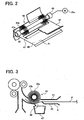
- Fig. 3 is a side view of the sheet carrier
- Fig. 4 is an exploded perspective view of the sheet carrier
- Fig. 5 is a plan view of a brush-like member
- Fig. 6 is a distribution chart of a hair transplantation rate of the brush-like member
- Fig. 7 is a side view of an image reader in the copying machine
- Fig. 8 is a side view of a post processing apparatus in the copying machine.
- the printer engine 3 includes a drum-like image carrier (photoconductor) 4, a charger 5 that uniformly charges the outer circumferential surface of the photoconductor 4, an exposure unit 6 that exposes the outer circumferential surface of the photoconductor 4 charged by the charger 5 based on image data, and forms an electrostatic latent image, a developing unit 7 that provides a toner to the electrostatic latent image and develops the electrostatic latent image into a toner image, a transfer and carrier unit 8 that transfers the developed toner image onto a sheet material P and carries the sheet material P, and a cleaning unit 9 that removes the residual toner on the photoconductor 4 after the transfer.
- the exposure unit 6 uses laser beams, and includes a light source, such as a laser diode, a polygon mirror that allows the laser beam to scan, a polygon motor, an
- the main unit 2 includes a transport route 12.
- a paper feed cassette 11, and a large-capacity paper feeder 10 is externally attached to the main unit 2.
- the sheet material P is provided from a large-capacity paper feeder 10 or the paper feed cassette 11, and carried on the transport route 12.
- a carrier roller pair 13 that carries the sheet material P, the printer engine 3, and a fixing unit 14 that fixes the toner image transferred onto the sheet material P are provided.
- a post processing unit 15 is mounted on the main unit 2, and performs the post processing to the sheet material P after the fixing unit 14 performs the fixing process to the sheet material P.
- the post processing unit 15 has a fixed tray 16, a movable tray 17, a paper reversing-and-ejecting unit that reverses the sheet material P ejected from the main unit 2 and ejects the sheet onto the fixed tray 16, a punching unit 18 that punches the sheet material P, and a stapler 19 that stacks and staples a plurality of sheet materials P.
- An image reader 23 is arranges above the main unit 2, and includes an auto document feeder 20 (hereinafter, "ADF 20"), a contact glass 21, and an optical reader 22.
- ADF 20 auto document feeder 20
- the auto document feeder (ADF) 20 automatically feeds original document to be read, the document to be read is placed on the contact glass 21, and the optical reader 22 reads the document automatically fed by the ADF 20 or the document placed on the contact glass 21.
- the optical reader 22 includes first and second traveling bodies 24 and 25 that travel at a speed of 2:1 parallel to the contact glass 21, a lens 26, and a photoelectric transducer 27 (, hereinafter "CCD 27").
- a light source 28 and a first mirror 29 are mounted on the first traveling unit 24.
- the light source 28 illuminates the document placed on the contact glass 21 or the document carried by the ADF 20, and the first mirror 29 reflects the light reflected by the document.
- a second mirror 30 and a third mirror 31 are mounted on the second traveling unit 25, and reflect the light reflected by the first mirror 29.
- the lens 26 and the CCD 27 are arranged ahead of the traveling direction of the light sequentially reflected by the first to third mirrors 29, 30, and 31.
- the copying machine 1 forms an image as described below.
- the optical reader 22 reads an image of the document placed on the contact glass 21 or an image automatically fed by the ADF 20.
- a semiconductor laser in the exposure unit 6 emits laser beams corresponding to the image data based on the read result.
- the laser beams expose the outer circumference surface of the photoconductor 4 that is uniformly charged by the charger 5, and an electrostatic latent image is thereby formed.
- the developing unit 7 supplies the toner to the electrostatic latent image. Consequently, the electrostatic latent image is developed and a toner image is formed.
- the sheet material P is supplied from the large-capacity paper feeder 10 or the paper feed cassettes 11, and is carried on the transport route 12.
- the toner image is transferred onto the sheet material P.
- the transfer-and-carrier unit 8 carries the sheet material P to the fixing unit 14, the fixing unit 14 performs the fixing processing to the sheet material P, and the sheet material P is carried to the post processing unit 15. Subsequently, the sheet material P is directly ejected onto the fixed tray 16, or a punching unit 18 and a stapler 19 (see Fig. 8 ) perform various types of post processing to the sheet material P.
- a carrier path A is formed such that a lower-sheet carrier guide 40 and an upper-sheet carrier guide 41 face each other, and the sheet material P is supplied from the large-capacity paper feeder 10 to the main unit 2 through the carrier path A.
- a separating/paper feeding roller 42 which is a separating/paper feeding member, rotates and separates the sheet material P loaded in the large-capacity paper feeder 10 one by one, and a carrier roller part 43 carries the sheet material P onto the lower-sheet carrier guide 40.
- An opening 44 is formed in the lower-sheet carrier guide 40.
- the opening 44 has a long shape that extends in the direction orthogonal to the transport direction of the sheet material P.
- a brush-like member 45 which is a paper-dust removal member, is rotatably arranged along on the axis that extends in the direction orthogonal to the transport direction of the sheet material P.
- the brush-like member 45 includes a columnar shaft 45a and a brush 45b that is radially provided on the outer circumferential surface of the shaft 45a. The hair of the brush 45b is directly transplanted on the outer circumferential surface of the shaft 45a.
- a holding unit 46 rotatably holds the brush-like member 45, and is mounted on both ends of the shaft 45a.
- a motor 45c drives the brush-like member 45 to rotate on the axis of the shaft 45a, and is connected to one of the ends of the shaft 45a.
- the brush-like member 45 is arranged such that the head of the brush 45b makes a contact with the surface of the lower-sheet carrier guide 40.
- the motor 45c drives the brush-like member 45, whose head makes a contact with the surface of the sheet material P, to rotate on the axis of the shaft 45a.
- the brush-like member 45 is driven so as to rotate the brush 45b in an opposite direction (counter direction) to the traveling direction of the sheet material P, at a portion where the brush-like member 45 makes a contact with the sheet material P. Therefore, the brush-like member 45 removes the paper dust that adheres to the sheet material P when the brush-like member 45 rotates. After the sheet material P passes above the opening 44, the paper dust removed from the sheet material P falls through the opening 44. Then the paper dust is stored in a paper dust box 47 arranged below the opening 44.
- a force Fp is a minimum sheet driving force Fp when the sheet material P carried on the lower-sheet carrier guide 40 makes a contact with the brush 45b of the brush-like member 45, and a resistance Rb is a maximum transport resistance Rb applied to the sheet material P by the brush-like member 45, the relation between the force Fp and the resistance Rb is always set to satisfy Fp>Rb. Therefore, when the sheet material P makes a contact with the brush 45b of the brush-like member 45, the sheet material P travels while rotating the brush-like member 45.
- the length of the opening 44 in the longitudinal direction (a direction orthogonal to the transport direction of the sheet material P) is set to La
- the length of the brush-like member 45 in the extending direction (a direction orthogonal to the transport direction of the sheet material P) is set to Lb.
- the sheet material P carried on the lower-sheet carrier guide 40 has a maximum sheet width Lp in the direction orthogonal to the transport direction of the sheet material P.
- the lengths La and Lb, and the maximum sheet width Lp are set to satisfy Lp ⁇ Lb ⁇ La. Accordingly, the brush-like member 45 removes the paper dust with respect to the sheet material P of all sizes, and the paper dust falls through the opening 44 without remaining on the lower-sheet carrier guide 40.
- the hair transplantation rate of the brush 45b indicates the number of hair transplantation of the brush 45b per unit area, and is partially different at positions along the axial direction of the shaft 45a of the brush-like member 45. Specifically, as shown in Figs. 5 and 6 , an area Rc, which is centered in the axial direction of the shaft 45b, has the highest hair transplantation rate, and areas Ra and Re, which are located at both ends, have the second highest one, and areas Rb and Rd, which are respectively between the areas Ra and Rc, and areas Rc and Re, have the lowest one.
- the area Rc is a part opposite to the area against which the separating/paper feeding roller 42 is pressed.
- the sheet material P is most likely to have the paper dust at the area Rc since the separating/paper feeding roller 42 is pressed against the area Rc.
- the areas Ra and Re are corresponding to both ends of the sheet material P in the transport direction of the sheet material P.
- the sheet material P is likely to have the paper dust at the both ends since the sheet material P makes a contact with the peripheral guide members while the sheet material P is being carried.
- the sheet material P is most unlikely to have the paper dust at the part facing the areas Rb and Rd while the paper material is being carried on the lower-sheet carrier guide 40.
- the hair transplantation rate of the brush 45b is partially different at positions along the axial direction of the brush-like member 45, and the hair transplantation rate of the brush 45b is increased in the area opposite to the part where the sheet material P is likely to have the paper dust, the paper dust is remove from the sheet material P efficiently.
- the transport resistance decreases by reducing the hair transplantation rate of the brush 45b in the area opposite to the part where the sheet material P is unlikely to have the paper dust.
- the brush-like member 45 is formed of an electroconductive material, an antistatic material, or a material subjected to an antistatic treatment.
- the holding unit 46 is also formed of the electroconductive material.
- the brush-like member 45 is formed of the electroconductive material, electricity is removed from the sheet material P when the brush-like member makes a contact with the sheet material P, and it is thereby prevented that the paper dust adheres to the sheet material P due to static electricity.
- the brush-like member 45 is formed of the antistatic material or is subjected to the antistatic treatment, it is prevented that the paper dust adheres to the brush-like member 45 due to the static electricity charged in the brush-like member 45.
- Fig. 7 is a side view of the image reader 23 in the copying machine 1.
- the image reader 23 also includes the sheet carrier unit that removes the paper dust that adheres to the sheet material (document).
- the sheet carrier unit includes a lower-sheet carrier guide 50, on which the document is carried, an opening 51, which is formed in the lower-sheet carrier guide 50, and a brush-like member 52, which is arranged above the opening 51 and corresponds to a paper-dust removal member that rotates on the axis.
- the opening 51, the brush-like member 52, and the paper dust box (not shown), which receives the paper dust that falls through the opening 51, respectively have the same configuration as the opening 44, the brush-like member 45, and the paper dust box 47.
- the optical reader 22 reads an image of the document, from which the paper dust is removed. Consequently, the high quality of the read image is obtained without being affected by the paper dust.
- Fig. 8 is a side view of the post processing unit 15 in the copying machine 1.
- the post processing unit 15 also includes the sheet carrier unit that removes the paper dust that adheres to the sheet material.
- the sheet carrier unit includes a lower-sheet carrier guide 60, on which the sheet material that has the fixed toner image is carried, an opening 61, which is formed in the lower-sheet carrier guide 60, and a brush-like member 62, which is arranged above the opening 61 and corresponds to the paper-dust removal member that rotates on the axis.
- the opening 61, the brush-like member 62, and the paper dust box (not shown), which receives the paper dust that falls through the opening 61, have the same configuration as the opening 44, the brush-like member 45, and the paper dust box 47, respectively.
- post processing is performed to the sheet material from which the paper dust is removed, without being affected by the paper dust.
- the sheet carrier unit according to the second embodiment has the basically same configuration as the sheet carrier unit according to the first embodiment, and includes the lower-sheet carrier guide 40 and the upper-sheet carrier guide 41 that face each other, and the opening 40, which is formed in the lower-sheet carrier guide 40 (see Figs. 2 and 3 ).
- Fig. 9 is an exploded perspective view of a brush-like member 70, which is a paper-dust removal member.
- the brush-like member 70 is arranged above the opening 44, and rotates on an axis that extends in a direction orthogonal to the, transport direction of the sheet material P.
- the brush-like member 70 includes a columnar shaft 70a, and brushes 70b and 70c that are radially provided on the outer circumferential surface of the shaft 70a.
- the hair of the brush 70b is directly transplanted on the outer circumferential surface of the shaft 70a.
- the hair of the brushes 70c is transplanted on the outer circumferential surface of a cylindrical member 70d, which is engaged with the shaft 70a so as to adjust the position along the axial direction of the shaft 70a.
- the shaft 70a penetrates the cylindrical member 70d while supporting the cylindrical member 70d.
- a pin 70e prevents the cylindrical member 70d from rotating, and a retaining ring 7f fixes the cylindrical member 70d in the axial direction of the shaft 70a.
- the position of the cylindrical member 70d is shifted by changing each position of the pin 70e and the retaining ring 70f.
- the cylindrical member 70d is a hollow body, and has inner diameter that engages with the outer diameter of the shaft 70a, which is a shaft member.
- the pin 70e is detachably inserted into a hole provided in the outer surface of the shaft 70a so as to fix the cylindrical member 70d.
- the cylindrical member 70d is fixed to the shaft 70a in the axial direction by detachably locking the retaining ring 70f in a groove provided on the outer surface of the shaft 70a.
- the brush 70c is supported by the cylindrical member 70d, and is detachably arranged so as to change the axial position with respect to the shaft 70a.
- the brush 70b is positioned in the center and fixed to the shaft 70a.
- the brush-like member 70 is arranged such that the head of the brushes 70b and 70c make a contact with the surface of the lower-sheet carrier guide 40 (see Figs. 2 and 3 ).
- the brush-like member 70 makes a contact with the surface of the sheet material P at the head of the brushes 70b and 70c, and the motor 45c rotates the brush-like member 70 on the axis of the shaft 70a. Since the brush-like member 70 rotates on the axis of the shaft 70a, paper dust that adheres to the sheet material P is removed. Then, after the sheet material P passes above the opening 44, the paper dust falls through the opening 44. Subsequently, the paper dust is stored in the paper dust box 47 that is arranged below the opening 44.
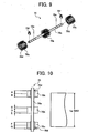
- Fig. 10 is a plan view of the brush-like member 70 and a sheet material P that has the maximum width
- Fig. 11 is a plan view of the brush-like member 70 and a sheet material P that has the minimum width
- Fig. 12 is a distribution chart of the hair transplantation rate of the brushes 70b and 70c shown in Fig. 11 .
- the hair transplantation rate of the brushes 70b and 70c is different partially at positions along the axial direction of the shaft 70a of the brush-like member 70. Specifically, as shown in Figs. 10 to 12 , an area D, which is centered in the axial direction of the shaft 70a, have the highest hair transplantation rate, areas A and G, which are located at both ends, have the second highest one, and the other areas B, C, E, and F have the lowest one.
- the area D is a part corresponding to the area against which the separating/paper feeding roller 42 is pressed.
- the sheet material P is most likely have the paper dust at the area D because the separating/paper feeding roller 42 is pressed against the area D.
- the areas A and G are parts that face both ends of the paper material P in the transport direction of the paper material P carried on the lower-sheet carrier guide 40.
- the sheet material P is most likely have the paper dust at the both opposite in the transport direction, because the sheet material makes a contact with the peripheral guide members while the sheet material P is being carried.
- the sheet material P is most unlikely to have the paper dust at the parts facing the areas B, C, E, and F while the sheet material P is being carried on the lower-sheet carrier guide 40.
- the positions of the areas A and G are adjustable by moving and fixing the positions selectively so as to correspond to the size of the sheet material P.
- the positions of the both ends of the sheet material P are thereby different. Therefore, in order to correspond to the different sizes, the positions of the areas A and G are adjusted and changed.
- the adjustable range is from the maximum size LpMAX, shown in Fig. 10 , to the minimum size LpMIN, shown in Fig. 11 , in a direction orthogonal to the transport direction of the sheet material P.
- the sheet material P is most unlikely to have the paper dust at the parts that face the areas B, C, E, and F. Therefore, the hair transplantation rate may be low.
- the paper dust is effectively removed from the sheet material P since the hair transplantation rate of the brushes 70b and 70c is partially different at positions along the axial direction of the shaft 70a. Further, the paper dust is effectively removed from the sheet material P since the positions are adjustable by selectively shifting and fixing the positions, and the hair transplantation of the brushes 70b and 70c thereby increases at the areas opposite to the parts where the sheet material P is likely to have the paper dust.
- the transport resistance with respect to the sheet material P decreases by reducing the hair transplantation rate of the brushes 70b and 70c in the areas opposite to the part where the sheet material P is unlikely to have the paper dust.
- the transport performance of the sheet material P can be maintained, and the sheet material P is prevented from bending, being turned up, or being unfed.
- the sheet carrier apparatus in this embodiment can be used in the image reader shown in Fig. 7 and in the post processing apparatus shown in Fig. 8 .
- the paper-dust removal member effectively removes the paper dust that adheres to the sheet material while the sheet material is being carried on the lower sheet carrier guide. Moreover, although a transport resistance is caused when the paper-dust removal member makes a contact with the carried sheet material, the transport resistance that acts on the sheet material is kept low. Even when the sheet material is thin or of low quality, the transport performance of the sheet material is maintained, and the sheet material is prevented from bending, being turned up, or being unfed.
- the head of the brush makes a contact with the sheet material while the sheet material is being carried, the paper dust that adheres to the sheet material is removed effectively. Moreover, since the head of the brush makes a contact with the sheet material, the transport resistance that acts on the sheet material by the brush-like member is kept low.
- the brush-like member rotates on the axis of the shaft while the head of the brush makes a contact with the sheet material, the paper dust that adheres to the sheet material is removed effectively.
- the paper dust is likely to be generated at an area against which the separating/paper feeding member is pressed, and at the both ends in the transport direction.
- the paper dust is effectively removed from the sheet material.
- the transport resistance which is caused by the contact of the brush with the sheet material, decreases as a whole. Consequently, even when the sheet material is thin or of low quality, the transport performance of the sheet material is maintained, and the sheet material is prevented from bending, being turned up, or being unfed.
- the positions of the parts where the hair transplantation rate of the brush is different is adjusted, and therefore, the hair transplantation rate of the part that faces the parts where the sheet material is likely to have the paper dust increases. Consequently, the paper dust that adheres to the sheet material is removed effectively.
- the present invention even when the size of the sheet material to be carried is different, by adjusting the positions of the parts, of the brush-like member, which the hair transplantation rate of the brush is high at, and faces the both ends in the transfer direction of the sheet material, the parts that have the high hair transplantation rate of the brush make a contact with the both ends of the sheet material that have various sizes. Consequently, the paper-dust removal performance is maintained.
- the paper dust is removed from the sheet material reliably, and then, the paper dust falls through the opening without remaining on the lower sheet carrier guide.
- the paper dust is removed by the brush-like member with respect to sheet materials of all sizes carried on the lower sheet carrier guide, and then, the paper dust falls through the opening.
- the brush-like member removes the paper dust from the sheet material with a higher performance.
- the paper dust that falls through the opening is stored in the paper dust box, thereby scattering of the paper dust that falls through the opening is prevented.
- the image forming apparatus since the image forming apparatus includes the sheet carrier apparatus according to the present invention, the image forming apparatus forms an image using the printer engine on the sheet material from which the paper dust has been removed. Consequently, the quality of images formed on the sheet material improves.
- the image reader since the image reader includes the sheet carrier apparatus according to the present invention, the optical reader reads an image on the sheet material from which paper dust is removed. Consequently, the optical reader reads an image of the sheet material with a higher performance.
- the post processing apparatus since the post processing apparatus includes the sheet carrier apparatus according to the present invention, the post processing apparatus performs post processing with respect to the sheet material from which paper dust is removed, and therefore, the performance of post processing improves.
Landscapes
- Feeding Of Articles By Means Other Than Belts Or Rollers (AREA)
Applications Claiming Priority (6)
| Application Number | Priority Date | Filing Date | Title |
|---|---|---|---|
| JP2004065364 | 2004-03-09 | ||
| JP2004065364 | 2004-03-09 | ||
| JP2004265959 | 2004-09-13 | ||
| JP2004265959 | 2004-09-13 | ||
| JP2004326972A JP4391923B2 (ja) | 2004-03-09 | 2004-11-10 | シート搬送装置、画像形成装置、画像読取装置及び後処理装置 |
| JP2004326972 | 2004-11-10 |
Publications (2)
| Publication Number | Publication Date |
|---|---|
| EP1574465A1 EP1574465A1 (en) | 2005-09-14 |
| EP1574465B1 true EP1574465B1 (en) | 2008-04-02 |
Family
ID=34830990
Family Applications (1)
| Application Number | Title | Priority Date | Filing Date |
|---|---|---|---|
| EP05003147A Expired - Fee Related EP1574465B1 (en) | 2004-03-09 | 2005-02-15 | Sheet carrier apparatus, image forming apparatus, image reader, and post-processing apparatus with paper-dust removal member. |
Country Status (4)
| Country | Link |
|---|---|
| US (1) | US7395009B2 (ja) |
| EP (1) | EP1574465B1 (ja) |
| JP (1) | JP4391923B2 (ja) |
| DE (1) | DE602005005731T2 (ja) |
Families Citing this family (6)
| Publication number | Priority date | Publication date | Assignee | Title |
|---|---|---|---|---|
| JP2005112630A (ja) * | 2003-09-17 | 2005-04-28 | Ricoh Co Ltd | シート搬送装置及びそれを備える画像形成装置、画像読取装置、後処理装置 |
| KR100677606B1 (ko) * | 2005-08-09 | 2007-02-02 | 삼성전자주식회사 | 급지카세트 및 이를 구비한 화상형성장치 |
| US8061834B2 (en) * | 2006-03-14 | 2011-11-22 | Brother Kogyo Kabushiki Kaisha | Printing apparatus including casing |
| US7740239B2 (en) * | 2006-12-22 | 2010-06-22 | Toshiba Tec Kabushiki Kaisha | Sheet processing apparatus |
| EP2298678B1 (de) * | 2009-09-18 | 2012-02-22 | Reifenhäuser GmbH & Co. Maschinenfabrik | Wickelvorrichtung |
| CN105346224A (zh) * | 2015-12-14 | 2016-02-24 | 重庆正合印务有限公司 | 一种纸箱印刷机 |
Family Cites Families (13)
| Publication number | Priority date | Publication date | Assignee | Title |
|---|---|---|---|---|
| US31154A (en) * | 1861-01-22 | Machine for reducing fibrous material | ||
| US4706320A (en) * | 1985-12-04 | 1987-11-17 | Xerox Corporation | Electrostatic charging and cleaning brushes |
| JPH01184177A (ja) * | 1988-01-19 | 1989-07-21 | Canon Inc | 記録装置 |
| JPH0216074A (ja) * | 1988-07-05 | 1990-01-19 | Nec Corp | 連続用紙の紙粉除去装置 |
| EP0371403B1 (en) * | 1988-11-26 | 1995-06-14 | Canon Kabushiki Kaisha | A sheet post-processing apparatus and image forming apparatus |
| JP2753844B2 (ja) * | 1989-01-12 | 1998-05-20 | 株式会社リコー | 紙搬送装置 |
| JPH0338793A (ja) * | 1989-07-06 | 1991-02-19 | Toshiba Corp | 通帳類処理装置 |
| JPH04195080A (ja) * | 1990-11-28 | 1992-07-15 | Ricoh Co Ltd | クリーニング装置 |
| JPH0553486A (ja) * | 1991-08-29 | 1993-03-05 | Sharp Corp | クリーニング装置 |
| JPH07215523A (ja) | 1994-01-31 | 1995-08-15 | Ricoh Co Ltd | 紙葉搬送装置 |
| JP3421893B2 (ja) * | 1995-07-17 | 2003-06-30 | 株式会社リコー | 定着装置 |
| JP3759295B2 (ja) * | 1997-08-22 | 2006-03-22 | 株式会社リコー | 原稿移動型読取装置 |
| US6505019B2 (en) * | 1998-09-30 | 2003-01-07 | Brother Kogyo Kabushiki Kaisha | Image forming apparatus having paper dust removing means |
-
2004
- 2004-11-10 JP JP2004326972A patent/JP4391923B2/ja not_active Expired - Fee Related
-
2005
- 2005-02-15 EP EP05003147A patent/EP1574465B1/en not_active Expired - Fee Related
- 2005-02-15 DE DE602005005731T patent/DE602005005731T2/de active Active
- 2005-03-09 US US11/074,780 patent/US7395009B2/en not_active Expired - Fee Related
Also Published As
| Publication number | Publication date |
|---|---|
| JP4391923B2 (ja) | 2009-12-24 |
| US20050201790A1 (en) | 2005-09-15 |
| JP2006103968A (ja) | 2006-04-20 |
| DE602005005731D1 (de) | 2008-05-15 |
| DE602005005731T2 (de) | 2009-05-07 |
| EP1574465A1 (en) | 2005-09-14 |
| US7395009B2 (en) | 2008-07-01 |
Similar Documents
| Publication | Publication Date | Title |
|---|---|---|
| JP4386034B2 (ja) | 画像形成装置 | |
| US8095035B2 (en) | Developing device, process unit, and image forming apparatus, with supporting members, grooves, and supported developing roller | |
| US7945192B2 (en) | Drive transmitting mechanism for an image forming apparatus | |
| EP1574465B1 (en) | Sheet carrier apparatus, image forming apparatus, image reader, and post-processing apparatus with paper-dust removal member. | |
| US9213272B2 (en) | Image forming apparatus including a holding member to hold a roller relative to a frame | |
| KR100327956B1 (ko) | 개선된 전사장치, 방법 및 상기 전사장치 혹은 방법을 사용하는 화상형성장치 | |
| US20070242973A1 (en) | Developing device and image forming apparatus | |
| US4988087A (en) | Sheet Stacker | |
| US7822366B2 (en) | Image forming apparatus and developing unit thereof | |
| JP4853478B2 (ja) | 画像形成装置及び両面印刷ユニット | |
| US7914215B2 (en) | Image forming apparatus | |
| JP2007024085A (ja) | 駆動力伝達装置および画像形成装置 | |
| US20110318079A1 (en) | Image forming apparatus and sheet feeding device | |
| US7447478B2 (en) | Image forming apparatus | |
| JP2006048014A (ja) | プロセスカートリッジ及び画像形成装置 | |
| JP2007070090A (ja) | シート供給装置及び画像形成装置 | |
| US7412195B2 (en) | Image forming apparatus having means to prevent image quality degradation | |
| JP3759885B2 (ja) | 画像形成装置 | |
| JP5168624B2 (ja) | 画像形成装置 | |
| US5162856A (en) | Abrasive, polishing and friction-reducing agent and means for applying the agent on an image carrier of an image forming apparatus | |
| US7065318B2 (en) | Paper feeder and image forming apparatus | |
| JP5723759B2 (ja) | 除電ユニット及びそれを備えたドラムユニット及び画像形成装置 | |
| JP7099083B2 (ja) | 光走査装置及び該光走査装置を備えた画像形成装置 | |
| JPH0934235A (ja) | 現像装置及びプロセスカートリッジ | |
| JP2007091383A (ja) | シート搬送装置、画像形成装置、画像読み取り装置、及び後処理装置 |
Legal Events
| Date | Code | Title | Description |
|---|---|---|---|
| PUAI | Public reference made under article 153(3) epc to a published international application that has entered the european phase |
Free format text: ORIGINAL CODE: 0009012 |
|
| AK | Designated contracting states |
Kind code of ref document: A1 Designated state(s): AT BE BG CH CY CZ DE DK EE ES FI FR GB GR HU IE IS IT LI LT LU MC NL PL PT RO SE SI SK TR |
|
| AX | Request for extension of the european patent |
Extension state: AL BA HR LV MK YU |
|
| 17P | Request for examination filed |
Effective date: 20050727 |
|
| AKX | Designation fees paid |
Designated state(s): DE FR GB |
|
| GRAP | Despatch of communication of intention to grant a patent |
Free format text: ORIGINAL CODE: EPIDOSNIGR1 |
|
| GRAS | Grant fee paid |
Free format text: ORIGINAL CODE: EPIDOSNIGR3 |
|
| GRAA | (expected) grant |
Free format text: ORIGINAL CODE: 0009210 |
|
| AK | Designated contracting states |
Kind code of ref document: B1 Designated state(s): DE FR GB |
|
| REG | Reference to a national code |
Ref country code: GB Ref legal event code: FG4D |
|
| REF | Corresponds to: |
Ref document number: 602005005731 Country of ref document: DE Date of ref document: 20080515 Kind code of ref document: P |
|
| ET | Fr: translation filed | ||
| PLBE | No opposition filed within time limit |
Free format text: ORIGINAL CODE: 0009261 |
|
| STAA | Information on the status of an ep patent application or granted ep patent |
Free format text: STATUS: NO OPPOSITION FILED WITHIN TIME LIMIT |
|
| 26N | No opposition filed |
Effective date: 20090106 |
|
| REG | Reference to a national code |
Ref country code: FR Ref legal event code: PLFP Year of fee payment: 12 |
|
| REG | Reference to a national code |
Ref country code: FR Ref legal event code: PLFP Year of fee payment: 13 |
|
| REG | Reference to a national code |
Ref country code: FR Ref legal event code: PLFP Year of fee payment: 14 |
|
| PGFP | Annual fee paid to national office [announced via postgrant information from national office to epo] |
Ref country code: GB Payment date: 20180216 Year of fee payment: 14 Ref country code: DE Payment date: 20180219 Year of fee payment: 14 |
|
| PGFP | Annual fee paid to national office [announced via postgrant information from national office to epo] |
Ref country code: FR Payment date: 20180223 Year of fee payment: 14 |
|
| REG | Reference to a national code |
Ref country code: DE Ref legal event code: R119 Ref document number: 602005005731 Country of ref document: DE |
|
| GBPC | Gb: european patent ceased through non-payment of renewal fee |
Effective date: 20190215 |
|
| PG25 | Lapsed in a contracting state [announced via postgrant information from national office to epo] |
Ref country code: DE Free format text: LAPSE BECAUSE OF NON-PAYMENT OF DUE FEES Effective date: 20190903 Ref country code: GB Free format text: LAPSE BECAUSE OF NON-PAYMENT OF DUE FEES Effective date: 20190215 |
|
| PG25 | Lapsed in a contracting state [announced via postgrant information from national office to epo] |
Ref country code: FR Free format text: LAPSE BECAUSE OF NON-PAYMENT OF DUE FEES Effective date: 20190228 |