EP1574464A1 - Dispositif de discrimination - Google Patents
Dispositif de discrimination Download PDFInfo
- Publication number
- EP1574464A1 EP1574464A1 EP05004356A EP05004356A EP1574464A1 EP 1574464 A1 EP1574464 A1 EP 1574464A1 EP 05004356 A EP05004356 A EP 05004356A EP 05004356 A EP05004356 A EP 05004356A EP 1574464 A1 EP1574464 A1 EP 1574464A1
- Authority
- EP
- European Patent Office
- Prior art keywords
- light
- subject
- discrimination
- planographic printing
- optical sensor
- Prior art date
- Legal status (The legal status is an assumption and is not a legal conclusion. Google has not performed a legal analysis and makes no representation as to the accuracy of the status listed.)
- Withdrawn
Links
- 230000003287 optical effect Effects 0.000 claims abstract description 59
- 238000002310 reflectometry Methods 0.000 claims abstract description 26
- 238000001514 detection method Methods 0.000 claims description 42
- 230000000979 retarding effect Effects 0.000 description 31
- 238000000926 separation method Methods 0.000 description 12
- 238000002835 absorbance Methods 0.000 description 9
- 239000003795 chemical substances by application Substances 0.000 description 8
- 238000011144 upstream manufacturing Methods 0.000 description 4
- 235000004443 Ricinus communis Nutrition 0.000 description 2
- 240000000528 Ricinus communis Species 0.000 description 2
- 239000000463 material Substances 0.000 description 2
- 238000012545 processing Methods 0.000 description 2
- 230000003595 spectral effect Effects 0.000 description 2
- XAGFODPZIPBFFR-UHFFFAOYSA-N aluminium Chemical compound [Al] XAGFODPZIPBFFR-UHFFFAOYSA-N 0.000 description 1
- 229910052782 aluminium Inorganic materials 0.000 description 1
- 239000004411 aluminium Substances 0.000 description 1
- 238000003780 insertion Methods 0.000 description 1
- 230000037431 insertion Effects 0.000 description 1
- 230000014759 maintenance of location Effects 0.000 description 1
- 230000000717 retained effect Effects 0.000 description 1
Images


Classifications
-
- B—PERFORMING OPERATIONS; TRANSPORTING
- B65—CONVEYING; PACKING; STORING; HANDLING THIN OR FILAMENTARY MATERIAL
- B65H—HANDLING THIN OR FILAMENTARY MATERIAL, e.g. SHEETS, WEBS, CABLES
- B65H7/00—Controlling article feeding, separating, pile-advancing, or associated apparatus, to take account of incorrect feeding, absence of articles, or presence of faulty articles
- B65H7/02—Controlling article feeding, separating, pile-advancing, or associated apparatus, to take account of incorrect feeding, absence of articles, or presence of faulty articles by feelers or detectors
- B65H7/06—Controlling article feeding, separating, pile-advancing, or associated apparatus, to take account of incorrect feeding, absence of articles, or presence of faulty articles by feelers or detectors responsive to presence of faulty articles or incorrect separation or feed
- B65H7/12—Controlling article feeding, separating, pile-advancing, or associated apparatus, to take account of incorrect feeding, absence of articles, or presence of faulty articles by feelers or detectors responsive to presence of faulty articles or incorrect separation or feed responsive to double feed or separation
- B65H7/125—Controlling article feeding, separating, pile-advancing, or associated apparatus, to take account of incorrect feeding, absence of articles, or presence of faulty articles by feelers or detectors responsive to presence of faulty articles or incorrect separation or feed responsive to double feed or separation sensing the double feed or separation without contacting the articles
Definitions
- the present invention relates to a discrimination device, and more specifically relates to a discrimination device which discriminates between two kinds of discrimination objects by utilizing light reflected therefrom or transmitted therethrough.
- the present invention is suitably applied to, for example, a discrimination device for identifying any of four possible discrimination objects, which are combinations structured by a planographic printing plate and/or a slip sheet.
- a discrimination device for discriminating between a planographic printing plate and a slip sheet, which protects a photosensitive surface of the planographic printing plate will be described.
- a slip sheet for protection is closely adhered to an image recording surface of a planographic printing plate, and these are often plurally stacked in a thickness direction to structure a plate sheaf of the planographic printing plates.
- material that has been extracted there are three cases: a state in which a slip sheet is adhered to a planographic printing plate, a planographic printing plate alone, and a slip sheet alone. There is also a state in which nothing has been extracted. Accordingly, it is preferable to be able to reliably discriminate between these four states, with a simple structure.
- JP-A Japanese Patent Application
- JP-A No. 2001-247254 describes a discrimination device in which a pair of optical sensors is disposed upward of alternately stacked photopolymer plates and slip sheets. A sensing level of one of these optical sensors is set lower than the other optical sensor. Consequently, with light reflected from a photopolymer plate, both the optical sensors are turned on, but with light reflected from a slip sheet, the one optical sensor is turned off. Thus, it is possible to discriminate between the photopolymer plates and the slip sheets.
- the present invention provides a discrimination device which is capable, with a simple structure, of reliably discriminating between four states structured by two types of discrimination subject, which differ in surface reflectivity.
- a first aspect of the present invention is a discrimination device for discriminating a type, from two types which differ in surface reflectivity, of a discrimination subject, the discrimination device comprising: a first optical sensor, the output of which switches to one of an ON state and an OFF state in accordance with presence of at least one of the two types of discrimination subject; a second optical sensor including a light detection portion which receives light reflected by the two types of discrimination subject, the output of the second optical sensor switching to one of an ON state and an OFF state in accordance with light reflected from, of the two types of discrimination subject, the type whose reflectivity is higher; and a third optical sensor including a light detection portion which receives light reflected by the two types of discrimination subject, the output of the third optical sensor switching to one of an ON state and an OFF state in accordance with light reflected from, of the two types of discrimination subject, the type whose reflectivity is lower.
- the first optical sensor switches to the ON state or the OFF state accordingly, and that presence can be sensed.
- the second optical sensor is switched to the ON state or OFF state thereof by light reflected from this high-reflectivity subject, and the presence of the high-reflectivity subject can be sensed.
- the third optical sensor is switched to the ON state or OFF state thereof by light reflected from this low-reflectivity subject, and the presence of the low-reflectivity subject can be sensed.
- the first optical sensor may include a light emission portion, which emits light to the discrimination subject, and a reflected light detection portion, on which reflected light that has been emitted by the light emission portion and reflected at a surface of the discrimination subject is incident.
- the first optical sensor includes the light emission portion, there is no need to additionally provide a light emission portion, and structure can be made simpler.
- the reflected light detection portion at which the reflected light that has been emitted by the light emission portion and reflected at the surface of the discrimination subject is incident, is provided at the first optical sensor, there is no need to perform positioning and the like of a reflected light detection portion.
- At least one of the second optical sensor and the third optical sensor may include a light emission portion, which emits light to the discrimination subject, and a scattered light detection portion, on which some of scattered light that has been emitted by the light emission portion and scattered at a surface of the discrimination subject is incident.
- one or both of the second optical sensor and the third optical sensor includes the light emission portion(s), there is no need to additionally provide a light emission portion, and structure can be made simpler.
- the scattered light detection portion at which the scattered light that has been emitted by the light emission portion and scattered at the surface of the discrimination subject is incident, is provided at the second/third optical sensor, there is no need to perform positioning and the like of a scattered light detection portion.
- the second optical sensor and the third optical sensor sensors which have, for example, the same structure as the first optical sensor may be employed.
- the second optical sensor and third optical sensor may be structured to be arranged at predetermined angles, such that reflected light from the discrimination subject is not directly incident thereon, or the like. Because sensors with the same structures can be employed as the optical sensors, costs can be lowered.
- the discrimination subject is structured by at least one of a planographic printing plate and a slip sheet which has been superposed with the planographic printing plate, the first optical sensor switches to the one of the ON state and the OFF state thereof in accordance with presence of either of the planographic printing plate and the slip sheet, the second optical sensor switches to the one of the ON state and the OFF state thereof in accordance with light reflected from the planographic printing plate, and the third optical sensor switches to the one of the ON state and the OFF state thereof in accordance with light reflected from the slip sheet.
- planographic printing plates and slip sheets are subject to completely different processings subsequent to, for example, separation thereof. Therefore, it is necessary that planographic printing plates and slip sheets are reliably separated and conveyed to different processing stages.
- the discrimination device described above it is possible to reliably discriminate between the four states structured by the planographic printing plates and slip sheets. Hence, it is possible to easily and reliably implement subsequent separation, conveyance, etc.
- the light emission portion(s) of the at least one of the second optical sensor and the third optical sensor may be capable of emitting light with a wavelength from 570 nm to 740 nm.
- a second aspect of the present invention is a discrimination device for discriminating a type and configuration of a subject, the discrimination device comprising: a first optical sensor, an output state of which switches in accordance with presence or absence of the subject; a second optical sensor including a light detection portion which receives light reflected from the subject, an output state of the second sensor switching in accordance with the light reflected from the subject if reflectivity of the subject is relatively high; and a third optical sensor including a light detection portion which receives light reflected from the subject, an output state of the third sensor switching in accordance with the light reflected from the subject if reflectivity of the subject is relatively low, wherein the type and configuration of the subject is discriminated on the basis of the output states of the first, second and third sensors.
- a third aspect of the present invention is a discrimination device for discriminating a conveyance configuration of a sheet which is conveyed along a path, the discrimination device comprising: a first sensor, an output state of which switches in accordance with presence or absence of the sheet in the path; a second sensor disposed at a side of one face of the sheet that is conveyed along the path, the second sensor including a light detection portion which receives light reflected from the sheet, and an output state of the second sensor switching in accordance with the light reflected from the sheet if reflectivity of the sheet is relatively high; and a third sensor disposed at a side of another face of the sheet that is conveyed along the path, the third sensor including a light detection portion which receives light reflected from the sheet, and an output state of the third sensor switching in accordance with the light reflected from the sheet if reflectivity of the sheet is relatively low, wherein the conveyance configuration of the sheet is discriminated on the basis of the output states of the first, second and third sensors.
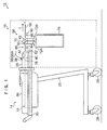
- Figure 1 shows general structure of a planographic printing plate supply apparatus 12 of a first embodiment of the present invention.
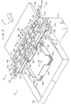
- Figure 2 shows a loading section 14 and a feeding section 16 of this planographic printing plate supply apparatus 12, in a state in which a plate sheaf 18 is loaded at the loading section 14.
- a photosensitive agent is coated onto one face of a support body, which is formed in a plate shape of aluminium or the like, to structure a photosensitive agent surface.
- slip sheets 22, which protect the photosensitive agent surfaces are stacked alternately with planographic printing plates 20 to structure the plate sheaf 18.
- the planographic printing plates 20 and slip sheets 22 are stacked such that the photosensitive agent surfaces face upward, and the slip sheet 22 that protects the photosensitive agent surface of the topmost planographic printing plate 20 has already been removed.
- a combination structured by one of the planographic printing plates 20 with the slip sheet 22 that is at the lower side thereof in this state is a unit of conveyance in 'joint feeding' (in other words, unit feeding), which is described later, and is accordingly referred to as a layer combination 24.
- Figures 4A to 4C show three conveyance configurations of the planographic printing plates 20 and slip sheets 22 being taken out from the planographic printing plate supply apparatus 12.
- Figure 4A is a conveyance configuration in which a topmost layer combination 24A, which is to say a topmost planographic printing plate 20A and a slip sheet 22A at the lower side thereof, are being taken out from the plate sheaf 18 as a single combination, which is below referred to as joint feeding.
- the planographic printing plates 20 and slip sheets 22 are referred to in general as conveyed mediums.
- Figure 4B is a conveyance configuration in which only a single planographic printing plate 20 is being taken out while no slip sheet 22 is being taken out, and is below referred to as 'individual feeding'.
- individual feeding includes a conveyance configuration in which one of the slip sheets 22 is being taken out alone, in a case in which that slip sheet 22 was in the topmost position.
- the state shown in Figure 4C is a conveyance configuration in which a plurality of the layer combinations 24 mentioned above are being taken out in a superposed state, and is below referred to as 'multiple joint feeding'.
- multiple joint feeding is prevented by adjustment of a load W that is applied to the plate sheaf 18 from a pick-up roller 42, which is described later, and, at least, consistent joint feeding is enabled (preferably, arbitrary switching between joint feeding and individual feeding is possible).
- FIG. 5A there are four conveyance combinations in the present embodiment: joint feeding (Figure 5A), absence of a conveyed medium (Figure 5B), individual conveyance of the slip sheet 22 alone (Figure 5C) and individual conveyance of the planographic printing plate 20 alone ( Figure 5D).
- a direction of feeding of the planographic printing plate 20 is represented by an arrow F and a direction intersecting therewith (a width direction of the planographic printing plate 20) is represented by an arrow W.
- the planographic printing plate supply apparatus 12 is provided with a table portion 26.
- the loading section 14 and the feeding section 16 are disposed on this table portion 26.
- Castors 28 are fitted to the table portion 26.
- the castors 28 enable movement of the planographic printing plate supply apparatus 12 as a whole, to associate/dissociate the planographic printing plate supply apparatus 12 with, for example, a planographic printing plate insertion portion of an exposure device or the like.
- the loading section 14 includes a level, rectangular loading tray 30.
- Two side end guide plates 32 and one rear end guide plate 34 are disposed in the loading tray 30.
- the side end guide plates 32 are slid in the the directions of arrow W by an unillustrated sliding mechanism to match the size of the planographic printing plates 20, and regulate positions of side faces of the plate sheaf 18, that is, of a plurality of the layer combinations 24.
- the rear end guide plate 34 is slid in the direction of arrow F (and a direction opposite thereto) by an unillustrated sliding mechanism and regulates the position of a rear end of the plate sheaf 18 (i.e., of the plurality of layer combinations 24).
- the loading section 14 is provided with a number of covers 36 such that a region at which the plate sheaf 18 is loaded is covered.
- a cover 36A covers a conveyance direction downstream side end portion of the plate sheaf 18.
- a holder 40 spans across along the width direction of the planographic printing plate 20.
- the pick-up roller 42 is rotatably mounted at the holder 40 so as to be disposed above the plate sheaf 18 that has been loaded in the loading section 14.
- Driving force from a driving motor 44 operates the pick-up roller 42 via an endless belt 46, and the pick-up roller 42 rotates (forward-rotates) in a direction for conveying conveyed mediums, that is, the planographic printing plates 20 and the slip sheets 22.
- the holder 40 is structured to be rotatable about support shafts 48, which are provided at both width direction ends of the holder 40, at the conveyance direction downstream side thereof.
- a drive unit 50 which is provided sideward of the holder 40, the pick-up roller 42 is rotated between a conveyance position, at which the pick-up roller 42 contacts the plate sheaf 18 and applies a predetermined load W thereto, and a withdrawn position, at which the pick-up roller 42 is separated from the plate sheaf 18.
- a bottom portion of the loading tray 30 is structured with a loading plate 52, which swings on an unillustrated hinge provided at the conveyance direction upstream side thereof.
- the loading plate 52 is urged upward by an unillustrated urging member and the topmost planographic printing plate 20 (or slip sheet 22) is assuredly contacted with the pick-up roller 42.
- Two guide plates 54 and 56 which are spaced apart by a predetermined gap in the conveyance direction, are disposed downstream in the conveyance direction relative to the loading section 14.
- the planographic printing plate 20 is supported by these guide plates 54 and 56 while being conveyed.
- a slip sheet separation apparatus 58 is disposed between the guide plates 54 and 56.
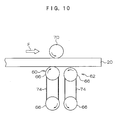
- the slip sheet separation apparatus 58 includes a conveyance roller unit 60 and a retarding roller unit 62, which are arranged in that order in the conveyance direction.
- Each of the conveyance roller unit 60 and the retarding roller unit 62 is structured by a rotatable shaft 64, which spans across along the width direction, and a plurality of rubber rollers 66, which are fixed to the shaft 64 and spaced by predetermined intervals.
- the retarding roller unit 62 is moved (raised and lowered), by a drive unit 68 provided at one end side thereof, between a contacting position for contacting the slip sheet 22 during conveyance (the position shown by solid lines in Figure 3) and a withdrawn position which is spaced apart from the slip sheet 22 (the position shown by broken lines in Figure 3).
- a drive unit 68 provided at one end side thereof, between a contacting position for contacting the slip sheet 22 during conveyance (the position shown by solid lines in Figure 3) and a withdrawn position which is spaced apart from the slip sheet 22 (the position shown by broken lines in Figure 3).
- the slip sheet 22 can be separated from the planographic printing plate 20.
- the rubber rollers 66 of the retarding roller unit 62 contact with the rubber rollers 66 of the conveyance roller unit 60 such that the slip sheet 22 can be nipped between the rubber rollers 66 of the retarding roller unit 62 and the rubber rollers 66 of the conveyance roller unit 60.
- a nipping roller 70 rotatably spans across along the width direction.
- the nipping roller 70 is caused to contact with the rubber rollers 66 of the conveyance roller unit 60 by the weight of the nipping roller 70, to enable nipping of the planographic printing plate 20 and slip sheet 22 between the nipping roller 70 and the rubber rollers 66 of the conveyance roller unit 60.
- the rubber rollers 66 of the conveyance roller unit 60 rotate in the direction of arrow R1
- the planographic printing plate 20 and slip sheet 22 are conveyed in the direction of arrow F.
- Slip sheet conveyance roller units 72A and 72B are disposed below the conveyance roller unit 60 and the retarding roller unit 62, respectively.
- both the conveyance roller units 72A and 72B are structured by others of the shafts 64 and rubber rollers 66, and are capable of nipping the slip sheet 22 therebetween.
- Endless driving belts 74 are wound round the shaft 64 of the conveyance roller unit 60 and the shaft 64 of the conveyance roller unit 72A, and the conveyance roller unit 72A rotates at the same times and in the same direction as the conveyance roller unit 60.
- others of the driving belts 74 are wound round the shaft 64 of the retarding roller unit 62 and the shaft 64 of the conveyance roller unit 72B.
- the nipped slip sheet 22 can be conveyed downward by the rubber rollers 66 of the conveyance roller units 72A and 72B rotating. At such a time, the slip sheet 22 is guided by the driving belts 74.
- a collection box 76 is provided below the conveyance roller units 72A and 72B to collect the slip sheets 22.
- a presence/absence sensor 78 and a discrimination sensor 80 are mounted at the holder 40, at the conveyance direction upstream side relative to the pick-up roller 42. Further, a presence/absence sensor 82 and a discrimination sensor 84 are arranged at the guide plate 54 in that order from the upstream side thereof. Upward of the presence/absence sensor 82 and discrimination sensor 84, a discrimination sensor 86 is retained by an unillustrated retention member. Further yet, a presence/absence sensor 88 and a discrimination sensor 90 are provided at the guide plate 56 in that order from the upstream side thereof.
- These presence/absence sensors 78, 82 and 88 detect the presence or absence of a conveyed medium (the planographic printing plate 20 and/or the slip sheet 22), and the discrimination sensors 80, 84, 86 and 90 identify whether the conveyed medium is the planographic printing plate 20 or the slip sheet 22.
- a notch 79 is formed in the loading plate 52 of the loading tray 30 to correspond with the presence/absence sensor 78.
- the plate sheaf 18 the planographic printing plates 20 and slip sheets 22
- light from the presence/absence sensor 78 is reflected by the planographic printing plate 20, and this reflected light is detected. If the plate sheaf 18 has not been loaded, the light from the presence/absence sensor 78 passes through the notch 79. Thus, the presence or absence of the plate sheaf 18 can be detected.
- the presence/absence sensor 82 and the discrimination sensors 84 and 86 structure a discrimination device 77 of the present invention.
- these sensors structuring the discrimination device 77 are discussed in detail with reference to table 1 and Figures 5A to 5D and 6A to 6G.
- Type of conveyed medium Planographic printing plate Slip sheet Planographic printing plate + slip sheet
- the presence/absence sensor 82 is structured by a light reflection-type sensor featuring a light emission portion 94 and a light detection portion 96.
- Light is irradiated from the light emission portion 94 and, if this light is reflected by the planographic printing plate 20 or slip sheet 22, which is a discrimination subject, and received by the light detection portion 96 (see Figure 6A), it is judged that a conveyed medium is present. If the light is not received by the light detection portion 96 (see Figure 6B), it is judged that the conveyed medium is absent.
- the illustrations of the presence/absence sensor 82 and the discrimination sensor 84 in Figures 6A to 6E are inverted in the vertical direction.
- the discrimination sensors 84 and 86 include others of the light emission portion 94 and light detection portion 96. However, as shown in Figures 6C, 6D and 6E, the discrimination sensors 84 and 86 are disposed to be inclined relative to the conveyed medium.
- the discrimination sensor 84 irradiates light to a rear face side of the planographic printing plate 20 and discriminates between the planographic printing plates 20 and the slip sheets 22 by intensities of reflected light, in accordance with a difference between surface reflectivities thereof. That is, in a case in which the slip sheet 22 is applied to the rear face of the planographic printing plate 20 (joint feeding) or a case of individual feeding of the slip sheet 22, the surface reflectivity of the slip sheet 22 is low and light is scattered by the slip sheet 22, as shown in Figure 6C. Because some of this scattered light is incident at the light detection portion 96, it can be detected that the slip sheet 22 is present.
- the discrimination sensor 84 is arranged such that the light reflected at the rear face is not incident at the light detection portion 96, as shown in Figure 6D, and it can thus be detected that the planographic printing plate 20 is present.
- this discrimination sensor 86 can be structured simply by arranging a sensor the same as the presence/absence sensor 82 to be inclined relative to the conveyed mediums.
- the discrimination sensor 86 utilizes a difference between absorbances of the planographic printing plates 20 and the slip sheets 22 to identify whether the conveyed medium is the planographic printing plate 20 or the slip sheet 22.
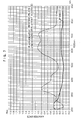
- Figure 7 shows an example of a difference between absorbance of the photosensitive agent surface of the planographic printing plate 20 and absorbance of the slip sheet 22.
- absorbance of the photosensitive agent surface is large but absorbance of the slip sheet 22 is not large, and a difference between these absorbances is large. Therefore, it is preferable to employ wavelengths in the range of 570 to 740 nm.
- a slip sheet detection sensor 92 is disposed between the conveyance roller units 72A and 72B, and the respectively corresponding conveyance roller unit 60 and retarding roller unit 62.
- the slip sheet detection sensor 92 can detect passage of the slip sheet 22.
- this slip sheet detection sensor 92 is structured by a light transmission-type sensor which is equipped with another of the light emission portion 94 and another of the light detection portion 96, as a pair which are disposed to face one another.
- sensors with structures the same as the presence/absence sensor 82 may be employed.
- sensors with structures the same as the presence/absence sensor 82 may be employed.
- a sensor with the same structure as the discrimination sensor 86 may be employed, and for the discrimination sensor 90, a sensor with the same structure as the discrimination sensor 84 may be employed.
- Respective attitudes of these sensors are not particularly limited as long as the action required of each sensor (detection or discrimination of the conveyed mediums) is reliably exhibited. However, if the presence/absence sensors 78, 82 and 88 are disposed, for example, with attitudes for which the angle of incidence of light on the conveyed medium is equal to the angle of reflection, reflected light can be detected more reliably, which is preferable.
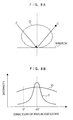
- Figure 8A shows spectral reflection characteristics of the planographic printing plates 20 and the slip sheets 22.
- Figure 8B shows relationships between directions of light reflected from conveyed mediums and intensities of the reflected light amounts.
- Z represents a direction of incident light
- C represents a direction of light reflected from the planographic printing plate 20
- D represents directions of light reflected from the slip sheet 22 (a range in which reflected light is comparatively strong).
- D represents directions of light reflected from the slip sheet 22 (a range in which reflected light is comparatively strong).
- Sensing information from the above-described presence/absence sensors 78, 82 and 88, the discrimination sensors 80, 84, 86 and 90, and the slip sheet detection sensor 92 is sent to an unillustrated control apparatus.
- the control apparatus controls respective portions of the planographic printing plate supply apparatus 12 on the basis of this information.
- planographic printing plate supply apparatus 12 structured as described above, when the planographic printing plates 20 are to be supplied to the exposure device, first, the plate sheaf 18 is placed in the loading section 14. At this time, a rear end 18B of the plate sheaf 18 is contacted with and aligned at the rear end guide plate 34, and the side ends of the plate sheaf 18 are contacted with and aligned at the side end guide plates 32.
- the cover 36A rotates upward and a portion of the plate sheaf 18 (a front end portion vicinity thereof) is exposed.
- the presence/absence sensor 78 detects the presence of the planographic printing plates 20 and the slip sheets 22 in the loading section 14. Consequently, the holder 40 is driven by the drive unit 50 and, as shown in Figure 4A, the pick-up roller 42 makes contact with the plate sheaf 18.
- the load W acting on the plate sheaf 18 from the pick-up roller 42 is adjusted for a case of individual feeding of the topmost planographic printing plate 20A alone or a case of joint feeding of the topmost planographic printing plate 20A and the topmost slip sheet 22A as a combination (in other words, the layer combination 24A, serving as a unit). Accordingly, it is possible to arbitrarily switch between individual feeding and joint feeding.
- a discrimination operation of the discrimination device 77 and splitting of the slip sheet 22 from the planographic printing plate 20 at the slip sheet separation apparatus 58 will be described, first for a case of joint feeding.
- the presence/absence sensor 82 is ON, the discrimination sensor 84 is ON and the discrimination sensor 86 is OFF, as shown in table 1. Accordingly, it can be determined that the feeding is joint feeding. Hence, the conveyance roller unit 60 and the retarding roller unit 62 are rotated.
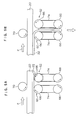
- the retarding roller unit 62 ascends, as shown by the solid lines in Figure 9A. Then, the rubber rollers 66 of the retarding roller unit 62 reverse-rotate and make contact with the slip sheet 22. Hence, a force from the conveyance roller unit 60 in the conveyance direction and a force from the retarding roller unit 62 in the direction opposite to the conveyance direction act on the slip sheet 22. Thus, the slip sheet 22 can be separated from the planographic printing plate 20.
- the slip sheet 22 is nipped by the rubber rollers 66 of the conveyance roller unit 60 and the retarding roller unit 62 and is conveyed downward. Consequently, although the presence/absence sensor 88 stays ON, sensing the presence of the planographic printing plate 20, the discrimination sensor 90 turns OFF and it is understood that the slip sheet 22 is not present thereat, which is to say that the slip sheet 22 has been removed from the planographic printing plate 20.
- the slip sheet detection sensor 92 senses the passage of the slip sheet 22 and, a predetermined amount of time after passage of a trailing end of the slip sheet 22 (for example, five seconds later), the conveyance roller unit 60 and the retarding roller unit 62 stop, and the retarding roller unit 62 descends to the withdrawn position.
- the planographic printing plate 20 from which the slip sheet 22 has been separated is detected by the presence/absence sensor 88 and the discrimination sensor 90.
- the planographic printing plate 20 is conveyed further and fed into the exposure device.
- the slip sheet 22 is collected in the collection box 76.
- the presence/absence sensor 82, the discrimination sensor 84 and the discrimination sensor 86 are ON, and individual feeding of the slip sheet 22 is reliably detected.
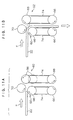
- the retarding roller unit 62 ascends to the contacting position before a leading end of the slip sheet 22 reaches that location, as shown in Figure 11A.
- the rubber rollers 66 of the retarding roller unit 62 have been moved into a conveyance path of the slip sheet 22, the leading end of the conveyed slip sheet 22 meets the rubber rollers 66 and the slip sheet 22 is guided downward, as shown in Figure 11B.
- the slip sheet 22 is nipped by the rubber rollers 66 of the conveyance roller unit 60 and the retarding roller unit 62 and is conveyed downward.
Landscapes
- Controlling Sheets Or Webs (AREA)
- Investigating Or Analysing Materials By Optical Means (AREA)
Applications Claiming Priority (2)
| Application Number | Priority Date | Filing Date | Title |
|---|---|---|---|
| JP2004056153A JP2005249403A (ja) | 2004-03-01 | 2004-03-01 | 判別装置 |
| JP2004056153 | 2004-03-01 |
Publications (1)
| Publication Number | Publication Date |
|---|---|
| EP1574464A1 true EP1574464A1 (fr) | 2005-09-14 |
Family
ID=34824505
Family Applications (1)
| Application Number | Title | Priority Date | Filing Date |
|---|---|---|---|
| EP05004356A Withdrawn EP1574464A1 (fr) | 2004-03-01 | 2005-02-28 | Dispositif de discrimination |
Country Status (3)
| Country | Link |
|---|---|
| US (1) | US7157725B2 (fr) |
| EP (1) | EP1574464A1 (fr) |
| JP (1) | JP2005249403A (fr) |
Families Citing this family (2)
| Publication number | Priority date | Publication date | Assignee | Title |
|---|---|---|---|---|
| US8427648B2 (en) | 2010-09-02 | 2013-04-23 | Eastman Kodak Company | Apparatus for discriminating between objects |
| US8570523B2 (en) | 2010-09-02 | 2013-10-29 | Eastman Kodak Company | Method for discriminating between objects |
Citations (4)
| Publication number | Priority date | Publication date | Assignee | Title |
|---|---|---|---|---|
| JPH0281846A (ja) * | 1988-09-15 | 1990-03-22 | Brother Ind Ltd | 用紙検出装置 |
| JPH0725516A (ja) * | 1993-07-15 | 1995-01-27 | Nec Corp | プリンタの印字用紙検出装置 |
| JP2001247254A (ja) * | 2000-03-07 | 2001-09-11 | Fuji Photo Film Co Ltd | 判別装置 |
| US20010022425A1 (en) * | 2000-03-15 | 2001-09-20 | Takashi Toyofuku | Sheet material positioning method and apparatus |
Family Cites Families (2)
| Publication number | Priority date | Publication date | Assignee | Title |
|---|---|---|---|---|
| JP2001356640A (ja) * | 2000-06-12 | 2001-12-26 | Rohm Co Ltd | 光センサ、判別装置および画像形成装置 |
| US6825484B2 (en) * | 2002-09-23 | 2004-11-30 | Creo Il. Ltd. | Surface reflectivity discriminating device |
-
2004
- 2004-03-01 JP JP2004056153A patent/JP2005249403A/ja active Pending
-
2005
- 2005-02-28 EP EP05004356A patent/EP1574464A1/fr not_active Withdrawn
- 2005-03-01 US US11/067,892 patent/US7157725B2/en not_active Expired - Fee Related
Patent Citations (5)
| Publication number | Priority date | Publication date | Assignee | Title |
|---|---|---|---|---|
| JPH0281846A (ja) * | 1988-09-15 | 1990-03-22 | Brother Ind Ltd | 用紙検出装置 |
| JPH0725516A (ja) * | 1993-07-15 | 1995-01-27 | Nec Corp | プリンタの印字用紙検出装置 |
| JP2001247254A (ja) * | 2000-03-07 | 2001-09-11 | Fuji Photo Film Co Ltd | 判別装置 |
| EP1136403A1 (fr) * | 2000-03-07 | 2001-09-26 | Fuji Photo Film Co., Ltd. | Dispositif discriminateur |
| US20010022425A1 (en) * | 2000-03-15 | 2001-09-20 | Takashi Toyofuku | Sheet material positioning method and apparatus |
Non-Patent Citations (3)
| Title |
|---|
| PATENT ABSTRACTS OF JAPAN vol. 014, no. 276 (M - 0984) 14 June 1990 (1990-06-14) * |
| PATENT ABSTRACTS OF JAPAN vol. 1995, no. 04 31 May 1995 (1995-05-31) * |
| PATENT ABSTRACTS OF JAPAN vol. 2000, no. 26 1 July 2002 (2002-07-01) * |
Also Published As
| Publication number | Publication date |
|---|---|
| US20050189504A1 (en) | 2005-09-01 |
| US7157725B2 (en) | 2007-01-02 |
| JP2005249403A (ja) | 2005-09-15 |
Similar Documents
| Publication | Publication Date | Title |
|---|---|---|
| JP3733361B2 (ja) | シート積載装置及び画像形成装置 | |
| JPH0281845A (ja) | 給紙装置 | |
| US7337889B2 (en) | Automated teller machine | |
| JPH0769485A (ja) | シート処理装置 | |
| US6425578B1 (en) | Image recording apparatus and method | |
| US7157725B2 (en) | Discrimination device for types or configurations of discrimination subjects | |
| KR100993752B1 (ko) | 지엽류 분리 조출 기구 | |
| US7370862B2 (en) | Apparatus for detecting double-feed of paper | |
| EP1136403B1 (fr) | Dispositif discriminateur | |
| JPH0741186A (ja) | 紙葉類の繰り出し機構 | |
| JP2783524B2 (ja) | 硬貨繰出装置 | |
| JP3412685B2 (ja) | 用紙搬送装置 | |
| JPH03259850A (ja) | カード送り装置 | |
| JP2008100828A (ja) | シート材供給装置 | |
| EP1571108B1 (fr) | Dispositif d'alimentation de plaque d'impression planographiques | |
| JP4707442B2 (ja) | 給紙装置 | |
| JP3944993B2 (ja) | 用紙搬送装置 | |
| JP7523998B2 (ja) | 媒体搬送装置 | |
| JP2002127349A (ja) | 印刷版供給における迎えガイド機構 | |
| JP2005041585A (ja) | シート搬送装置及びこれを搭載した画像形成装置 | |
| JPH0662178A (ja) | 画像読み取り装置 | |
| JP2001122450A (ja) | シート給送装置及び画像形成装置 | |
| JP2000289867A (ja) | シート給送装置及び画像処理装置 | |
| JP2005239326A (ja) | シート材供給装置 | |
| JPH0667457U (ja) | レシーブマガジンの状態検出機構 |
Legal Events
| Date | Code | Title | Description |
|---|---|---|---|
| PUAI | Public reference made under article 153(3) epc to a published international application that has entered the european phase |
Free format text: ORIGINAL CODE: 0009012 |
|
| AK | Designated contracting states |
Kind code of ref document: A1 Designated state(s): AT BE BG CH CY CZ DE DK EE ES FI FR GB GR HU IE IS IT LI LT LU MC NL PL PT RO SE SI SK TR |
|
| AX | Request for extension of the european patent |
Extension state: AL BA HR LV MK YU |
|
| 17P | Request for examination filed |
Effective date: 20051025 |
|
| AKX | Designation fees paid |
Designated state(s): DE FR GB |
|
| RAP1 | Party data changed (applicant data changed or rights of an application transferred) |
Owner name: FUJIFILM CORPORATION |
|
| 17Q | First examination report despatched |
Effective date: 20070601 |
|
| STAA | Information on the status of an ep patent application or granted ep patent |
Free format text: STATUS: THE APPLICATION IS DEEMED TO BE WITHDRAWN |
|
| 18D | Application deemed to be withdrawn |
Effective date: 20071012 |