EP1573158B1 - Türaussengriff, verfahren zum verhindern des öffnens einer fahrzeugtür bei einem seitenaufprall und verwendung einer verformung einer kraftfahrzeugtür zum verhindern des öffnens der tür - Google Patents
Türaussengriff, verfahren zum verhindern des öffnens einer fahrzeugtür bei einem seitenaufprall und verwendung einer verformung einer kraftfahrzeugtür zum verhindern des öffnens der tür Download PDFInfo
- Publication number
- EP1573158B1 EP1573158B1 EP03782353.1A EP03782353A EP1573158B1 EP 1573158 B1 EP1573158 B1 EP 1573158B1 EP 03782353 A EP03782353 A EP 03782353A EP 1573158 B1 EP1573158 B1 EP 1573158B1
- Authority
- EP
- European Patent Office
- Prior art keywords
- door
- door handle
- deformation
- lock
- external
- Prior art date
- Legal status (The legal status is an assumption and is not a legal conclusion. Google has not performed a legal analysis and makes no representation as to the accuracy of the status listed.)
- Expired - Lifetime
Links
- 238000000034 method Methods 0.000 title claims description 5
- 230000002265 prevention Effects 0.000 title claims 5
- 238000001514 detection method Methods 0.000 claims description 8
- 230000001133 acceleration Effects 0.000 claims description 7
- 230000008878 coupling Effects 0.000 claims description 6
- 238000010168 coupling process Methods 0.000 claims description 6
- 238000005859 coupling reaction Methods 0.000 claims description 6
- 230000003213 activating effect Effects 0.000 claims description 3
- 230000000903 blocking effect Effects 0.000 claims 2
- 230000000717 retained effect Effects 0.000 claims 1
- 230000004888 barrier function Effects 0.000 description 3
- 239000002184 metal Substances 0.000 description 3
- 230000006835 compression Effects 0.000 description 2
- 238000007906 compression Methods 0.000 description 2
- 230000004913 activation Effects 0.000 description 1
- 238000012790 confirmation Methods 0.000 description 1
- 238000005070 sampling Methods 0.000 description 1
- 125000006850 spacer group Chemical group 0.000 description 1
Images

Classifications
-
- E—FIXED CONSTRUCTIONS
- E05—LOCKS; KEYS; WINDOW OR DOOR FITTINGS; SAFES
- E05B—LOCKS; ACCESSORIES THEREFOR; HANDCUFFS
- E05B77/00—Vehicle locks characterised by special functions or purposes
- E05B77/02—Vehicle locks characterised by special functions or purposes for accident situations
- E05B77/04—Preventing unwanted lock actuation, e.g. unlatching, at the moment of collision
-
- E—FIXED CONSTRUCTIONS
- E05—LOCKS; KEYS; WINDOW OR DOOR FITTINGS; SAFES
- E05B—LOCKS; ACCESSORIES THEREFOR; HANDCUFFS
- E05B77/00—Vehicle locks characterised by special functions or purposes
- E05B77/02—Vehicle locks characterised by special functions or purposes for accident situations
- E05B77/04—Preventing unwanted lock actuation, e.g. unlatching, at the moment of collision
- E05B77/06—Preventing unwanted lock actuation, e.g. unlatching, at the moment of collision by means of inertial forces
Definitions
- the invention relates to an outside door handle for a locking device of a motor vehicle according to the preamble of claim 1, and a method according to the preamble of claim 15.
- a mass is arranged such that it exerts a counter-moment in the event of a crash on the handle bar or a part connected to the handle, so that due to the mass accelerations no opening of the door can take place.
- a generic prior art is for example from the DE 196 10 200 known.
- WO 02/14636 A proposes to provide a self-closing device for a vehicle door spacer compensation means that prevents actuation of the door lock in the case of sheet metal deformation.
- a locking device in which the lock release lever of the vehicle interior is connected via a strut with the lock bolt, wherein the strut can be decoupled in the event of a side impact from the release lever or the lock bolt.
- the invention is therefore an object of the invention to provide an outside door handle of the type mentioned, as well as a method for preventing the opening of a vehicle door in which it can not come to an opening of the door in a side impact even with strong sheet metal deformations.
- the door panel between the housing part and the handle bar can deform so that on the handle a force is exerted that causes the handle bar to an opening movement.
- deformation of the sheet is detected by means of a scanning means and, upon detection of deformation of the door, locking of the lock operating means, e.g. a swing arm, or alternatively a decoupling of the means for lock operation causes, in which the coupling of the means for lock operation, e.g. of the swivel arm, with the lock being lifted.
- This can be done for example by decoupling a cable, which is connected to the device for lock actuation.
- the scanning device may consist of a sensor device which activates the device in the presence of a crash detection signal.
- the device can be activated electrically, hydraulically, pneumatically, by radio or mechanically.
- the device consists for example of a bolt which can engage in a recess of the device for lock actuation or means for lock actuation, e.g. a cable, can decouple.
- the actuation of the bolt of the device can take place with the aid of an actuator.
- the scanning device preferably consists of a pivotable lever which scans the door on the inside and which actuates the device when the door is deformed.
- the lever can rest on the door or even at a distance from the door parallel to this.
- the pivotable lever has two lever arms, one of which scans a door deformation and the other in the case of a door deformation activates the device.
- the device activating lever arm for example, mechanically actuate the bolt of the device via a push rod.
- the bolt of the locking device can be integrally connected to the free end of the push rod.
- a weight may be fixed rigidly to the lever arm activating the device, which accelerates the pivoting movement of the pivotable lever in the event of a side impact against the door.
- the scanning point of the scanning device is arranged at a distance from the handle bar. Preference is given to a sampling point, which is arranged in the direction of travel of the vehicle in front of the handle.
- the device that can block the device for lock operation preferably has a predetermined breaking point, so that in an emergency after an accident, the door can still be opened by using higher forces.
- the invention advantageously provides for the use of deformation of the door panel in a side impact against a door of a motor vehicle to prevent the door from being opened by detecting the deformation with a scanner and mechanically transferring the deformation to a device having a Blocked operation of a lock confirmation device or the coupling of the device for lock operation with the castle canceled.
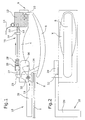
- the in Fig. 1 outer door handle shown comprises a housing part 4, in which at one end 8, a handle bar 6 is hooked hinged to a fixed bearing 11, wherein at the other end 9 of the housing part 4, a projection 10 of the handle bracket 6 engages through the door 2 into the inside and with a pivot arm 12 is coupled, which may be pivotable about a vertical axis.
- a pivot arm 12 is also pivoted, wherein a not shown in the drawing lock the locking device is opened via a cable 14 so that the door 2 of the vehicle can be opened.
- the device for lock operation consists of the projection 10 of the It is understood that the projection 10 itself may also be coupled directly to the cable 14 as part of the device for lock actuation.
- a portion of the door panel of the door 2 is shown only in the front area of the outside door handle.
- a mechanical scanning device 18 is arranged, which is pivotable about a preferably vertical axis 32 and consists of a two-armed lever.
- the two-armed lever has a parallel or substantially parallel to the door 2 extending lever arm 20, which may for example have a horizontal portion and at the end of the horizontal portion has a vertical portion, as shown Fig. 2 seen.
- the other lever arm 25 of the scanning device 18 acts on a serving as means 16 push rod 27, which is guided in mounted on the housing part 4 guides 24,26.
- the push rod 27 can be held in its inactivated starting position by means of a compression spring 28 which presses against a collar of the push rod 27.
- the lever arm 20 can be pressed against the inside of the door 2, for example by means of the compression spring 28, or be held for example by means of a stop in the guide 26 at a predetermined distance from the door 2, so that smaller deformations of the door surface not to a Activation of the device 16, ie in the embodiment can not lead to a locking of the pivot arm 12 and thus of the castle.
- the lever 20, 25 has such a length that the scanning point of the scanning device 18 lies at a distance, for example in the direction of travel of the vehicle, in front of the grip bar 6. This takes into account that the door deformation most frequently progresses from front to back.
- the guides 24 and 26, and in this case preferably the guide 24, can exert a latching function, so that the bolt 22 can not spring back after actuation.
- the bolt 22 operates in the embodiments of FIGS. 1 and 3 as a locking pin and engages in a recess 23 of the pivot arm 12, so that it can not pivot in the event of a crash.
- the pin 22 of the device 16 can be used to decouple the cable 14 from the pivot arm 12, for example, by the connector of the cable 14 is ejected from the coupling with the pivot arm 12.
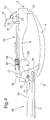
- Fig. 3 shows the operation of the scanner 18 and the device 16 as a locking device in the event of deformation of the door panel.
- the force exerted on the handle bar 6 by the deformed door panel forces between the housing part 4 and the handle bar 6 at the front end 8 can no longer cause a pivoting movement of the handle bracket 6 in the arrow direction, since due to the successful pivotal movement of the lever arm 20 of the locking pin 22 in the recess 23 of the pivot arm 12 is inserted and therefore the pivot arm 12 and thus also the cable 14 and the projection 10 of the handle bar 6 blocked.
- a mass 30 can be rigidly coupled to the lever arm 25, which not only compensates for the inertia of the lever arm 20 in the event of a side impact, but also enables additional acceleration of the locking bolt 22.
- the swing arm 12 may, as in particular Fig. 3 can be seen, which already have known mass barrier, which compensates for the forces resulting from the inertia of the handle bar 6 by a counter torque.
- the scanning device can also consist of a side impact detecting sensor device, which can be arranged on the door 2, for example in the form of strain gauges.
- Fig. 4 shows a second embodiment in which the projection 10 of the handle bar 6 is integrally connected to a rigid pivot arm 12, which in turn is coupled to the cable 14.
- the pivot arm 12 is provided with a recess 23 for receiving the locking pin 22 of the push rod 27.
- the linkage lever 34 which is pivotable about a fixed bearing 11, designed as a separate part that can be inserted into the handle bar 6.
Landscapes
- Lock And Its Accessories (AREA)
Description
- Die Erfindung betrifft einen Türaußengriff für eine Schließeinrichtung eines Kraftfahrzeuges nach dem Oberbegriff des Anspruchs 1, sowie ein Verfahren nach dem Oberbegriff des Anspruchs 15.
- Es sind sogenannte Massensperren bekannt, mit denen verhindert werden kann, dass im Falle eines Seitenaufpralls gegen eine Fahrzeugtür aufgrund der auf den Griffbügel ausgeübten Beschleunigungen ein Verschwenken des Griffbügels und somit ein Öffnen der Tür erfolgt.
- Bei einer derartigen Massensperre wird eine Masse derart angeordnet, dass sie im Crashfall ein Gegenmoment auf den Griffbügel oder ein mit dem Griffbügel verbundenes Teil ausübt, derart dass aufgrund der Massenbeschleunigungen kein Öffnen der Tür erfolgen kann.
- Ein gattungsgemäßer Stand der Technik ist beispielsweise aus der
DE 196 10 200 bekannt. - Es hat sich allerdings herausgestellt, dass nicht nur die Massenbeschleunigungen, sondern auch die Blechverformung zu einer unerwünschten Zwangsöffnung der Tür führen kann.
-
WO 02/14636 A - Aus der
GB 2361675 A - Der Erfindung liegt daher die Aufgabe zugrunde, einen Türaußengriff der eingangs genannten Art, sowie ein Verfahren zum Verhindern des Öffnens einer Fahrzeugtür zu schaffen, bei denen es auch bei starken Blechverformungen nicht zu einer Öffnung der Tür bei einem Seitenaufprall kommen kann.
- Zur Lösung dieser Aufgabe dienen die Merkmale des Anspruchs 1, bzw. des Anspruchs 15 sowie des Anspruchs 17.
- Bei einer Verformung der Tür kann sich das Türblech zwischen dem Gehäuseteil und dem Griffbügel so verformen, dass auf den Griffbügel eine Kraft ausgeübt wird, die den Griffbügel zu einer Öffnungsbewegung veranlasst. Nach der Erfindung wird eine solche Verformung des Blechs mit Hilfe einer Abtasteinrichtung detektiert und bei Feststellung einer Verformung der Tür eine Sperrung der Einrichtung zur Schlossbetätigung, z.B. eines Schwenkarms, oder alternativ eine Entkopplung der Einrichtung zur Schlossbetätigung bewirkt, bei der die Kopplung der Einrichtung zur Schlossbetätigung z.B. des Schwenkarms, mit dem Schloss aufgehoben wird. Dies kann beispielsweise durch Entkopplung eines Seilzuges erfolgen, der mit der Einrichtung zur Schlossbetätigung verbunden ist.
- Die Abtasteinrichtung kann aus einer Sensoreinrichtung bestehen, die beim Vorliegen eines Crash-Feststellungssignals die Einrichtung aktiviert.
- Beim Vorliegen eines Crash-Feststellungssignals kann die Einrichtung elektrisch, hydraulisch, pneumatisch, per Funk oder mechanisch aktiviert werden.
- Die Einrichtung besteht beispielsweise aus einem Bolzen, der in eine Aussparung der Einrichtung zur Schlossbetätigung eingreifen kann oder eine Einrichtung zur Schlossbetätigung, z.B. einen Seilzug, entkoppeln kann.
- Dabei kann die Betätigung des Bolzens der Einrichtung mit Hilfe eines Aktuators erfolgen.
- Die Abtasteinrichtung besteht vorzugsweise aus einem innenseitig die Tür abtastenden schwenkbaren Hebel, der bei Verformung der Tür die Einrichtung betätigt. Dabei kann der Hebel an der Tür anliegen oder auch mit Abstand von der Tür parallel zu dieser verlaufen.
- Bei einem bevorzugten Ausführungsbeispiel ist vorgesehen, dass der schwenkbare Hebel zwei Hebelarme aufweist, von denen einer eine Türverformung abtastet und der andere im Falle einer Türverformung die Einrichtung aktiviert.
- Dabei kann der die Einrichtung aktivierende Hebelarm beispielsweise mechanisch über eine Schubstange den Bolzen der Einrichtung betätigen. Dabei kann der Bolzen der Sperreinrichtung einstückig mit dem freien Ende der Schubstange verbunden sein.
- An dem die Einrichtung aktivierenden Hebelarm kann desweiteren ein Gewicht starr befestigt sein, das im Falle eines Seitenaufpralls gegen die Tür die Schwenkbewegung des schwenkbaren Hebels beschleunigt.
- Vorzugsweise ist vorgesehen, dass der Abtastpunkt der Abtasteinrichtung mit Abstand von dem Griffbügel angeordnet ist. Bevorzugt ist dabei ein Abtastpunkt, der in Fahrtrichtung des Fahrzeugs vor dem Griffbügel angeordnet ist.
- Die Einrichtung, die die Einrichtung zur Schlossbetätigung blockieren kann, weist vorzugsweise eine Sollbruchstelle auf, so dass im Notfall nach einem Unfall die Tür unter Aufwendung höherer Kräfte dennoch geöffnet werden kann.
- Die Erfindung sieht demzufolge in vorteilhafter Weise die Verwendung der bei einem Seitenaufprall gegen eine Tür eines Kraftfahrzeuges entstehenden Verformung des Türblechs zum Verhindern des Öffnens der Tür vor, indem die Verformung mit einer Abtasteinrichtung detektiert wird und die Verformung mechanisch auf eine Einrichtung übertragen wird, die eine Betätigung einer Einrichtung zur Schlossbestätigung blockiert oder die Kopplung der Einrichtung zur Schlossbetätigung mit dem Schloss aufhebt.
- Im folgenden wird unter Bezugnahme auf die Zeichnungen ein Ausführungsbeispiel der Erfindung näher erläutert.
- Es zeigen:
- Fig. 1
- den erfindungsgemäßen Türaußengriff in einer Draufsicht,
- Fig. 2
- eine Seitenansicht von
Fig. 1 , - Fig. 3
- die Lage der Funktionselemente im Falle einer Türverformung, und
- Fig. 4
- ein zweites Ausführungsbeispiel.
- Der in
Fig. 1 dargestellte Türaußengriff umfasst ein Gehäuseteil 4, in dem an einem Ende 8 ein Griffbügel 6 an einem Festlager 11 gelenkig eingehakt ist, wobei an dem anderen Ende 9 des Gehäuseteils 4 ein Vorsprung 10 des Griffbügels 6 durch die Tür 2 hindurch in die Innenseite eingreift und mit einem Schwenkarm 12 gekoppelt ist, der um eine vertikale Achse schwenkbar sein kann. Wenn der Griffbügel 6 nach außen gezogen wird, wird der Schwenkarm 12 ebenfalls verschwenkt, wobei ein in der Zeichnung nicht dargestelltes Schloss der Schließeinrichtung über einen Seilzug 14 geöffnet wird, damit die Tür 2 des Fahrzeuges geöffnet werden kann. Die Einrichtung zur Schlossbetätigung besteht demzufolge aus dem Vorsprung 10 des Griffbügels 6, dem Schwenkarm 12 und dem Seilzug 14. Es versteht sich, dass der Vorsprung 10 selbst als Bestandteil der Einrichtung zur Schlossbetätigung auch direkt mit dem Seilzug 14 gekoppelt sein kann. - In der
Fig. 1 und3 ist ein Abschnitt des Türblechs der Tür 2 nur im vorderen Bereich des Türaußengriffs dargestellt. - An dem vorderen Ende 8 des Gehäuseteils 4 ist eine mechanische Abtasteinrichtung 18 angeordnet, die um eine vorzugsweise vertikale Achse 32 schwenkbar ist und aus einem zweiarmigen Hebel besteht. Der zweiarmige Hebel weist einen parallel oder im wesentlichen parallel zu der Tür 2 verlaufenden Hebelarm 20 auf, der beispielsweise einen horizontalen Abschnitt und an dem Ende des horizontalen Abschnitts einen vertikalen Abschnitt aufweisen kann, wie aus
Fig. 2 ersichtlich. Der andere Hebelarm 25 der Abtasteinrichtung 18 wirkt auf eine als Einrichtung 16 dienende Schubstange 27 ein, die in an dem Gehäuseteil 4 befestigten Führungen 24,26 geführt ist. Die Schubstange 27 kann mit Hilfe einer Druckfeder 28, die gegen einen Bund der Schubstange 27 drückt, in ihrer inaktivierten Ausgangslage gehalten werden. Dabei kann der Hebelarm 20 beispielsweise mit Hilfe der Druckfeder 28 gegen die Innenseite der Tür 2 angedrückt werden, oder auch beispielsweise mit Hilfe eines Anschlags in der Führung 26 in einem vorbestimmten Abstand von der Tür 2 gehalten werden, damit kleinere Verformungen der Türfläche nicht zu einer Aktivierung der Einrichtung 16, d.h. in dem Ausführungsbeispiel nicht zu einer Verriegelung des Schwenkarms 12 und damit des Schlosses führen können. - Der Hebel 20,25 weist eine derartige Länge auf, dass der Abtastpunkt der Abtasteinrichtung 18 mit Abstand beispielsweise in Fahrtrichtung des Fahrzeugs vor dem Griffbügel 6 liegt. Dies berücksichtigt, dass die Türverformung am häufigsten von vorne nach hinten fortschreitet.
- Die Führungen 24 und 26, und hierbei vorzugsweise die Führung 24, kann eine Rastfunktion ausüben, so dass der Bolzen 22 nach Betätigung nicht zurückspringen kann.
- Der Bolzen 22 arbeitet in den Ausführungsbeispielen der
Fign. 1 und3 als Sperrbolzen und greift in eine Aussparung 23 des Schwenkarms 12 ein, so dass dieser im Crashfall nicht verschwenken kann. - Alternativ kann der Bolzen 22 der Einrichtung 16 dazu verwendet werden, den Seilzug 14 von dem Schwenkarm 12 zu entkoppeln, indem beispielsweise der Anschlussteil des Seilzuges 14 aus der Kopplung mit dem Schwenkarm 12 ausgestoßen wird. Hierzu wäre allerdings eine geringfügig andere Anordnung der Elemente als in
Fig. 1 gezeigt erforderlich, bei der das Anschlussteil koaxial zu dem Bolzen 22 verläuft. -
Fig. 3 zeigt die Arbeitsweise der Abtasteinrichtung 18 und der Einrichtung 16 als Sperreinrichtung im Falle der Verformung des Türblechs. Die auf den Griffbügel 6 durch das verformte Türblech ausgeübten Kräfte zwischen dem Gehäuseteil 4 und dem Griffbügel 6 an dem vorderen Ende 8 können nicht mehr eine Schwenkbewegung des Griffbügels 6 in Pfeilrichtung bewirken, da aufgrund der erfolgten Schwenkbewegung des Hebelarms 20 der Sperrbolzen 22 in die Aussparung 23 des Schwenkarms 12 eingeführt ist und daher den Schwenkarm 12 und somit auch den Seilzug 14 und den Vorsprung 10 des Griffbügels 6 blockiert. - An dem Hebelarm 25 kann zusätzlich starr eine Masse 30 angekoppelt sein, die bei einem Seitenaufprall die Trägheit des Hebelarms 20 nicht nur kompensiert, sondern darüber hinaus auch eine zusätzliche Beschleunigung des Sperrbolzens 22 ermöglicht.
- Der Schwenkarm 12 kann, wie insbesondere aus
Fig. 3 ersichtlich, die für sich schon bekannte Massensperre aufweisen, die die aufgrund der Trägheit des Griffbügels 6 entstehenden Kräfte durch ein Gegendrehmoment kompensiert. - Bei den in den Zeichnungen nicht dargestellten alternativen Ausführungsformen kann die Abtasteinrichtung auch aus einer einen Seitenaufprall detektierenden Sensoreinrichtung bestehen, die beispielsweise in Form von Dehnungsmessstreifen an der Tür 2 angeordnet sein können.
-
Fig. 4 zeigt ein zweites Ausführungsbeispiel, bei dem der Vorsprung 10 des Griffbügels 6 einstückig mit einem starren Schwenkarm 12 verbunden ist, der seinerseits mit dem Seilzug 14 gekoppelt ist. - Der Schwenkarm 12 ist mit einer Aussparung 23 zur Aufnahme des Sperrbolzens 22 der Schubstange 27 versehen.
- An dem anderen Ende des Griffbügels ist der Anlenkhebel 34, der um ein Festlager 11 schwenkbar ist, als separates Teil gestaltet, das in den Griffbügel 6 einsteckbar ist.
- Im übrigen entspricht das Ausführungsbeispiel der
Fig. 4 dem Ausführungsbeispiel derFign. 1 bis 3 . - Die Erfindung wurde anhand eines Griffsbügels eines Zuggriffs erläutert. Es versteht sich allerdings, dass sie auch bei Klappgriffen, bei denen der Griff um eine im wesentlichen horizontale Achse verschwenkbar ist, angewandt werden kann.
Claims (17)
- Türaußengriff für eine Schließeinrichtung eines Kraftfahrzeuges, mit einem an der Tür (2) befestigten Gehäuseteil (4) und einem Griffbügel (6), der in dem Gehäuseteil (4) gelenkig gehalten ist und mit einer in dem Gehäuseteil (4) gelagerten Einrichtung (10,12,14) zur Schlossbetätigung der Schließeinrichtung gekoppelt ist, sowie mit einer Einrichtung zum Verhindern des Öffnens der Tür (2) bei einem Seitenaufprall gegen die Tür (2),
dadurch gekennzeichnet,
dass die Einrichtung zum Verhindern des Öffnens der Tür (2) eine Abtasteinrichtung (18) aufweist, die eine Verformung der Tür (2) detektiert und eine Einrichtung (16) aktiviert, die eine Betätigung der Einrichtung (10, 12, 14) zur Schlossbetätigung infolge der Beschleunigung des Türaußengriffs bei einem Seitenaufprall blockiert, oder dadurch gekennzeichnet, dass die Einrichtung zum Verhindern des Öffnens der Tür (2) eine in Bezug auf das Gehäuseteil (4) bewegbare Abtasteinrichtung (18) aufweist, die eine Verformung der Tür (2) detektiert und eine Einrichtung (16) aktiviert, die die Kopplung der Einrichtung (10, 12, 14) zur Schlossbetätigung mit dem Schloss aufhebt. - Türaußengriff nach Anspruch 1, dadurch gekennzeichnet, dass die Abtasteinrichtung (18) aus einer Sensoreinrichtung besteht, die die Verformung der Tür detektiert und bei dem Vorliegen eines Crash-Feststellungssignals die Einrichtung (16) aktiviert.
- Türaußengriff nach Anspruch 1 oder 2, dadurch gekennzeichnet, dass beim Vorliegen eines Crash-Feststellungssignals die Einrichtung (16) elektrisch, hydraulisch, pneumatisch, per Funk oder mechanisch aktiviert ist.
- Türaußengriff nach einem der Ansprüche 1 bis 3, dadurch gekennzeichnet, dass die Einrichtung (16) aus einem Bolzen (22) besteht, der in eine Aussparung (23) der Einrichtung zur Schlossbetätigung (10,12,14) eingreift oder die Einrichtung zur Schlossbetätigung (10,12,14) von dem Schloss entkoppelt.
- Türaußengriff nach einem der Ansprüche 1 bis 4, dadurch gekennzeichnet, dass die Betätigung der Einrichtung (16) mit Hilfe eines Aktuators erfolgt.
- Türaußengriff nach einem der Ansprüche 1 bis 5, dadurch gekennzeichnet, dass die Abtasteinrichtung (18) aus einem innenseitig die Tür (2) abtastenden schwenkbaren Hebel besteht, der bei Verformung der Tür die Einrichtung (16) aktiviert.
- Türaußengriff nach Anspruch 6, dadurch gekennzeichnet, dass der schwenkbare Hebel zwei Hebelarme (20,25) aufweist, von denen einer eine Türverformung abtastet und der andere im Falle der Türverformung die Einrichtung (16) betätigt.
- Türaußengriff nach Anspruch 7, dadurch gekennzeichnet, dass der Hebelarm (25) mechanisch über eine Schubstange (27) die Einrichtung (16) betätigt.
- Türaußengriff nach einem der Ansprüche 6 bis 8, dadurch gekennzeichnet, dass an dem Hebelarm (25) ein Gewicht (30) befestigt ist, das im Falle eines Seitenaufpralls gegen die Tür (2) die Schwenkbewegung des schwenkbaren Hebels (20,25) beschleunigt.
- Türaußengriff nach einem der Ansprüche 1 bis 9, dadurch gekennzeichnet, dass der Abtastpunkt der Abtasteinrichtung (18) in Fahrtrichtung gesehen mit Abstand vor dem Griffbügel (6) angeordnet ist.
- Türaußengriff nach einem der Ansprüche 1 bis 10, dadurch gekennzeichnet, dass die Einrichtung (16), die den Schwenkarm (10,12,14) blockiert, eine Sollbruchstelle aufweist.
- Türaußengriff nach einem der Ansprüche 1 bis 11, dadurch gekennzeichnet, dass ein Anlenkhebel (34) am Griffbügel (6) steckbar angeordnet ist.
- Türaußengriff nach einem der Ansprüche 1 bis 12, dadurch gekennzeichnet, dass die Einrichtung zur Schlossbetätigung (10,12,14) einen Schwenkarm (12) aufweist.
- Türaußengriff nach Anspruch 13, dadurch gekennzeichnet, dass der Schwenkarm (12) einstückig an dem Vorsprung (10) des Griffbügels angeformt ist.
- Verfahren zum Verhindern des Öffnens einer Tür (2) infolge der Beschleunigung eines Türaußengriffs einer Schließeinrichtung eines Kraftfahrzeuges, wobei der Türaußengriff mit einer Einrichtung (10,12,14) zur Schlossbetätigung gekoppelt ist, dadurch gekennzeichnet, dass- eine Verformung an einer Tür (2) eines Kraftfahrzeuges zum Detektieren eines Seitenaufpralls durch eine Abtasteinrichtung (18) abgetastet wird, und- beim Detektieren eines Seitenaufpralls eine Einrichtung (16) zum Blockieren der Einrichtung (10, 12, 14) zur Schlossbetätigung aktiviert wird, oder dadurch gekennzeichnet, dass eine Verformung an einer Tür (2) eines Kraftfahrzeuges zum Detektieren eines Seitenaufpralls durch eine in Bezug auf ein Gehäuseteil (4) des Türaußengriffs bewegbare Abtasteinrichtung (18) abgetastet wird, und beim Detektieren eines Seitenaufpralls eine Einrichtung (16) zum Aufheben der Kopplung der Einrichtung (10, 12, 14) zur Schlossbetätigung mit dem Schloss einer Schliesseinrichtung aktiviert wird.
- Verfahren nach Anspruch 15, dadurch gekennzeichnet, dass die Türverformung mechanisch über Hebel (20,25) abgetastet wird, der bei einem Seitenaufprall eine Schubstange (27) betätigt, durch die eine Einrichtung zur Schlossbetätigung (10,12,14) blockiert wird oder durch die die Kopplung der Einrichtung (10,12,14) zur Schlossbetätigung mit dem Schloss aufgehoben wird.
- Verwendung der bei einem Seitenaufprall gegen eine Tür eines Kraftfahrzeuges erfolgenden Verformung zum Verhindern des Öffnens der Tür (2) infolge der Beschleunigung eines einen Griffbügel aufweisenden Türaußengriffs einer Schließeinrichtung, wobei der Türaußengriff mit einer Einrichtung (10,12,14) zur Schlossbetätigung gekoppelt ist, wobei das Verhindern des Öffnens der Tür durch Detektieren der Verformung mit einer Abtasteinrichtung (18) und durch Übertragen der Verformung auf eine Einrichtung (16), die eine Betätigung der Einrichtung (10, 12, 14) des Türaußengriffs zur Schlossbetätigung blockiert, erreicht wird oder wobei das Verhindern des Öffnens der Tür , durch Detektieren der Verformung mit einer in Bezug auf ein Gehäuseteil (4) des Türaußengriffs bewegbaren Abtasteinrichtung (18) und durch Übertragen der Verformung auf eine Einrichtung (16), die eine Betätigung der Einrichtung (10, 12, 14) zur Schloßbetätigung mit dem Schloß aufhebt, erreicht wird.
Applications Claiming Priority (3)
| Application Number | Priority Date | Filing Date | Title |
|---|---|---|---|
| DE10260900 | 2002-12-20 | ||
| DE10260900A DE10260900A1 (de) | 2002-12-20 | 2002-12-20 | Türaußengriff |
| PCT/EP2003/013971 WO2004059112A1 (de) | 2002-12-20 | 2003-12-10 | Türaussengriff und verfahren zum verhindern des öffnens einer fahrzeugtür bei einem seitenaufprall |
Publications (2)
| Publication Number | Publication Date |
|---|---|
| EP1573158A1 EP1573158A1 (de) | 2005-09-14 |
| EP1573158B1 true EP1573158B1 (de) | 2015-11-04 |
Family
ID=32404261
Family Applications (1)
| Application Number | Title | Priority Date | Filing Date |
|---|---|---|---|
| EP03782353.1A Expired - Lifetime EP1573158B1 (de) | 2002-12-20 | 2003-12-10 | Türaussengriff, verfahren zum verhindern des öffnens einer fahrzeugtür bei einem seitenaufprall und verwendung einer verformung einer kraftfahrzeugtür zum verhindern des öffnens der tür |
Country Status (4)
| Country | Link |
|---|---|
| EP (1) | EP1573158B1 (de) |
| AU (1) | AU2003290001A1 (de) |
| DE (1) | DE10260900A1 (de) |
| WO (1) | WO2004059112A1 (de) |
Cited By (1)
| Publication number | Priority date | Publication date | Assignee | Title |
|---|---|---|---|---|
| TWI830767B (zh) * | 2018-08-30 | 2024-02-01 | 德商安博歐葛斯特布雷米克索尼公司 | 鎖 |
Families Citing this family (18)
| Publication number | Priority date | Publication date | Assignee | Title |
|---|---|---|---|---|
| FR2869340B1 (fr) * | 2004-04-22 | 2009-01-09 | Peugeot Citroen Automobiles Sa | Dispositif d'ouverture d'un ouvrant de vehicule automobile muni de moyens pour empecher l'ouverture de l'ouvrant en cas de choc lateral |
| FR2897575B1 (fr) * | 2006-02-22 | 2008-05-16 | Renault Sas | Porte de vehicule automobile pourvue d'un dispositif de detection d'une collision laterale. |
| GB2462116B (en) * | 2008-07-25 | 2012-03-21 | Gm Global Tech Operations Inc | Vehicle side door assembly |
| DE102008062213A1 (de) * | 2008-12-13 | 2010-06-17 | Dr.Ing.H.C.F.Porsche Aktiengesellschaft | Türgriffeinrichtung |
| DE102008062214B4 (de) * | 2008-12-13 | 2023-07-20 | Dr. Ing. H.C. F. Porsche Aktiengesellschaft | Türgriffeinrichtung |
| FR2946077A1 (fr) * | 2009-05-26 | 2010-12-03 | Peugeot Citroen Automobiles Sa | Dispositif de commande de l'ouverture d'un ouvrant d'un vehicule automobile comportant un moyen pour empecher cette ouverture, en cas de choc lateral, ouvrant ainsi equipe et vehicule comportant un tel ouvrant. |
| JP5738607B2 (ja) * | 2011-01-26 | 2015-06-24 | トヨタ車体株式会社 | ドアの閉ロック装置 |
| US8727402B2 (en) * | 2012-09-27 | 2014-05-20 | Ford Global Technologies, Llc | Deformation driven blocking mechanism for an automobile |
| DE102012025053A1 (de) | 2012-12-21 | 2014-06-26 | BROSE SCHLIEßSYSTEME GMBH & CO. KG | Kraftfahrzeugschloss |
| DE102013004835A1 (de) | 2013-03-21 | 2013-09-19 | Daimler Ag | Fahrzeugtür |
| DE102014015949A1 (de) * | 2014-10-30 | 2016-05-04 | Huf Hülsbeck & Fürst Gmbh & Co. Kg | Kraftfahrzeugtürgriffanordnung mit Unfallsicherung |
| KR101827147B1 (ko) * | 2016-09-12 | 2018-02-07 | 현대자동차주식회사 | 도어 아웃사이드 핸들 |
| FR3079544B1 (fr) * | 2018-03-27 | 2022-06-10 | Mgi Coutier Espana Sl | Dispositif de commande d'ouverture a blocage de securite inertiel |
| US11041328B2 (en) | 2018-03-30 | 2021-06-22 | Kiekert Ag | Latching device for a motor vehicle |
| DE102018113918A1 (de) * | 2018-06-11 | 2019-12-12 | Volkswagen Aktiengesellschaft | Einrichtung zur Aufrechterhaltung eines verriegelten Zustands einer Kraftfahrzeugtür und Kraftfahrzeug |
| CN110541630B (zh) * | 2019-08-28 | 2021-03-16 | 安徽江淮汽车集团股份有限公司 | 安全把手及其控制方法 |
| FR3103141A1 (fr) * | 2019-11-20 | 2021-05-21 | Renault S.A.S | Agencement pour ouvrant de véhicule avec moyen de blocage maintenant l’ouvrant fermé en cas de choc. |
| DE102020105986A1 (de) | 2020-03-05 | 2021-09-09 | Bayerische Motoren Werke Aktiengesellschaft | Türgriffanordnung eines Fahrzeugs |
Family Cites Families (6)
| Publication number | Priority date | Publication date | Assignee | Title |
|---|---|---|---|---|
| GB1442394A (en) * | 1973-02-08 | 1976-07-14 | Gen Motors Ltd | Vehicle door with latch |
| DE19610200A1 (de) * | 1996-03-15 | 1997-09-18 | Valeo Deutschland Gmbh & Co | Türaußengriff |
| DE19845393C2 (de) * | 1998-10-02 | 2000-08-31 | Daimler Chrysler Ag | Öffnungsvorrichtung für eine Fahrzeugtür |
| DE19912682A1 (de) * | 1999-03-20 | 2000-09-21 | Volkswagen Ag | Verschlußanordnung für eine Kraftfahrzeug-Seitentür |
| GB2361675B (en) * | 2000-04-26 | 2002-12-31 | Meritor Light Vehicle Sys Ltd | Passenger door |
| DE10041498B4 (de) * | 2000-08-11 | 2005-10-27 | Brose Fahrzeugteile Gmbh & Co. Kg, Coburg | Schließeinrichtung für eine Fahrzeugtür |
-
2002
- 2002-12-20 DE DE10260900A patent/DE10260900A1/de not_active Ceased
-
2003
- 2003-12-10 WO PCT/EP2003/013971 patent/WO2004059112A1/de not_active Ceased
- 2003-12-10 AU AU2003290001A patent/AU2003290001A1/en not_active Abandoned
- 2003-12-10 EP EP03782353.1A patent/EP1573158B1/de not_active Expired - Lifetime
Cited By (1)
| Publication number | Priority date | Publication date | Assignee | Title |
|---|---|---|---|---|
| TWI830767B (zh) * | 2018-08-30 | 2024-02-01 | 德商安博歐葛斯特布雷米克索尼公司 | 鎖 |
Also Published As
| Publication number | Publication date |
|---|---|
| EP1573158A1 (de) | 2005-09-14 |
| DE10260900A1 (de) | 2004-07-01 |
| AU2003290001A1 (en) | 2004-07-22 |
| WO2004059112A1 (de) | 2004-07-15 |
Similar Documents
| Publication | Publication Date | Title |
|---|---|---|
| EP1573158A1 (de) | Türaussengriff und verfahren zum verhindern des öffnens einer fahrzeugtür bei einem seitenaufprall | |
| EP3423313B1 (de) | Klappenscharnier für eine frontklappe eines fahrzeugs mit einer verschiebbaren lagerung eines hubaktuators | |
| DE3927265C3 (de) | Insassenschutzeinrichtung für Kraftfahrzeuge mit einem Überrollbügel | |
| DE10033148B4 (de) | Haubenkonstruktion für ein Fahrzeug | |
| DE60120320T2 (de) | Mechanismus zum Anheben der Motorhaube eines Kraftfahrzeuges | |
| DE102009031744A1 (de) | Fahrzeugseitentürenanordnung | |
| DE102016010672A1 (de) | Verriegelungsvorrichtung für eine Fahrzeugtür und Verfahren | |
| DE102004062105B4 (de) | Vorrichtung zum Schutz von Personen bei einem Frontalaufprall auf ein Kraftfahrzeug durch aktives Aufstellen dessen Fronthaube | |
| EP1608529B1 (de) | Kopfstützenanordnung für einen kraftfahrzeugsitz | |
| WO2016177635A1 (de) | Schliessbügelanordnung zum wahlweisen rückhalten oder rotatorischen freigeben einer frontklappe eines kraftfahrzeuges | |
| EP1604086A2 (de) | Kraftfahrzeug | |
| DE3502574C1 (de) | UEberrollschutz fuer ein Kraftfahrzeug mit einem offenen Aufbau | |
| EP3002396B1 (de) | Handhabe | |
| DE102007063540A1 (de) | Fahrzeugkarosserie und Fahrzeug | |
| EP3423314B1 (de) | Klappenscharnier für eine frontklappe eines fahrzeugs mit einem teleskopierbaren lenkerhebel | |
| DE102008039731A1 (de) | Haubenverschlussvorrichtung | |
| DE10350533B4 (de) | Vorrichtung zum Schutz von Personen bei einem Frontalaufprall auf ein Kraftfahrzeug durch aktives Aufstellen dessen Fronthaube | |
| DE10318717B3 (de) | Fahrzeugsitz, insbesondere Kraftfahrzeugsitz | |
| DE19808374B4 (de) | Vorrichtung zum Verriegeln einer Abdeckung nach Art einer Karosseriehaube eines Kraftfahrzeugs | |
| DE102004055604A1 (de) | Scharnier | |
| DE10352275B4 (de) | Einrichtung zum Reversieren einer zum Unfallschutz sensorgesteuert aktiv aufgestellten Fronthaube eines Kraftfahrzeuges | |
| EP1538287B1 (de) | Türaussengriff | |
| EP1039076B1 (de) | Verschlussanordnung für eine Kraftfahrzeug-Seitentür | |
| DE4311287A1 (de) | Sicherheitsentriegelung für über Kopf bewegbare Torblätter | |
| DE102015203517A1 (de) | Schließbügelanordnung zum wahlweisen Rückhalten oder Freigeben einer Frontklappe eines Kraftfahrzeuges |
Legal Events
| Date | Code | Title | Description |
|---|---|---|---|
| PUAI | Public reference made under article 153(3) epc to a published international application that has entered the european phase |
Free format text: ORIGINAL CODE: 0009012 |
|
| 17P | Request for examination filed |
Effective date: 20050608 |
|
| AK | Designated contracting states |
Kind code of ref document: A1 Designated state(s): AT BE BG CH CY CZ DE DK EE ES FI FR GB GR HU IE IT LI LU MC NL PT RO SE SI SK TR |
|
| AX | Request for extension of the european patent |
Extension state: AL LT LV MK |
|
| DAX | Request for extension of the european patent (deleted) | ||
| 17Q | First examination report despatched |
Effective date: 20070111 |
|
| RIN1 | Information on inventor provided before grant (corrected) |
Inventor name: MOENIG, STEFAN Inventor name: MUELLER, DIRK |
|
| REG | Reference to a national code |
Ref country code: DE Ref legal event code: R079 Ref document number: 50315371 Country of ref document: DE Free format text: PREVIOUS MAIN CLASS: E05B0065120000 Ipc: E05B0077040000 |
|
| GRAP | Despatch of communication of intention to grant a patent |
Free format text: ORIGINAL CODE: EPIDOSNIGR1 |
|
| RIC1 | Information provided on ipc code assigned before grant |
Ipc: E05B 77/04 20140101AFI20150429BHEP |
|
| INTG | Intention to grant announced |
Effective date: 20150515 |
|
| GRAS | Grant fee paid |
Free format text: ORIGINAL CODE: EPIDOSNIGR3 |
|
| GRAA | (expected) grant |
Free format text: ORIGINAL CODE: 0009210 |
|
| AK | Designated contracting states |
Kind code of ref document: B1 Designated state(s): AT BE BG CH CY CZ DE DK EE ES FI FR GB GR HU IE IT LI LU MC NL PT RO SE SI SK TR |
|
| REG | Reference to a national code |
Ref country code: GB Ref legal event code: FG4D Free format text: NOT ENGLISH |
|
| REG | Reference to a national code |
Ref country code: CH Ref legal event code: EP |
|
| REG | Reference to a national code |
Ref country code: AT Ref legal event code: REF Ref document number: 759317 Country of ref document: AT Kind code of ref document: T Effective date: 20151115 |
|
| REG | Reference to a national code |
Ref country code: IE Ref legal event code: FG4D Free format text: LANGUAGE OF EP DOCUMENT: GERMAN |
|
| REG | Reference to a national code |
Ref country code: DE Ref legal event code: R096 Ref document number: 50315371 Country of ref document: DE |
|
| REG | Reference to a national code |
Ref country code: FR Ref legal event code: PLFP Year of fee payment: 13 |
|
| REG | Reference to a national code |
Ref country code: NL Ref legal event code: MP Effective date: 20151104 |
|
| PG25 | Lapsed in a contracting state [announced via postgrant information from national office to epo] |
Ref country code: IT Free format text: LAPSE BECAUSE OF FAILURE TO SUBMIT A TRANSLATION OF THE DESCRIPTION OR TO PAY THE FEE WITHIN THE PRESCRIBED TIME-LIMIT Effective date: 20151104 Ref country code: ES Free format text: LAPSE BECAUSE OF FAILURE TO SUBMIT A TRANSLATION OF THE DESCRIPTION OR TO PAY THE FEE WITHIN THE PRESCRIBED TIME-LIMIT Effective date: 20151104 Ref country code: NL Free format text: LAPSE BECAUSE OF FAILURE TO SUBMIT A TRANSLATION OF THE DESCRIPTION OR TO PAY THE FEE WITHIN THE PRESCRIBED TIME-LIMIT Effective date: 20151104 |
|
| PG25 | Lapsed in a contracting state [announced via postgrant information from national office to epo] |
Ref country code: BE Free format text: LAPSE BECAUSE OF NON-PAYMENT OF DUE FEES Effective date: 20151231 Ref country code: GR Free format text: LAPSE BECAUSE OF FAILURE TO SUBMIT A TRANSLATION OF THE DESCRIPTION OR TO PAY THE FEE WITHIN THE PRESCRIBED TIME-LIMIT Effective date: 20160205 Ref country code: FI Free format text: LAPSE BECAUSE OF FAILURE TO SUBMIT A TRANSLATION OF THE DESCRIPTION OR TO PAY THE FEE WITHIN THE PRESCRIBED TIME-LIMIT Effective date: 20151104 Ref country code: PT Free format text: LAPSE BECAUSE OF FAILURE TO SUBMIT A TRANSLATION OF THE DESCRIPTION OR TO PAY THE FEE WITHIN THE PRESCRIBED TIME-LIMIT Effective date: 20160304 Ref country code: SE Free format text: LAPSE BECAUSE OF FAILURE TO SUBMIT A TRANSLATION OF THE DESCRIPTION OR TO PAY THE FEE WITHIN THE PRESCRIBED TIME-LIMIT Effective date: 20151104 |
|
| PG25 | Lapsed in a contracting state [announced via postgrant information from national office to epo] |
Ref country code: CZ Free format text: LAPSE BECAUSE OF FAILURE TO SUBMIT A TRANSLATION OF THE DESCRIPTION OR TO PAY THE FEE WITHIN THE PRESCRIBED TIME-LIMIT Effective date: 20151104 |
|
| REG | Reference to a national code |
Ref country code: CH Ref legal event code: PL |
|
| REG | Reference to a national code |
Ref country code: DE Ref legal event code: R097 Ref document number: 50315371 Country of ref document: DE |
|
| PG25 | Lapsed in a contracting state [announced via postgrant information from national office to epo] |
Ref country code: RO Free format text: LAPSE BECAUSE OF FAILURE TO SUBMIT A TRANSLATION OF THE DESCRIPTION OR TO PAY THE FEE WITHIN THE PRESCRIBED TIME-LIMIT Effective date: 20151104 Ref country code: SK Free format text: LAPSE BECAUSE OF FAILURE TO SUBMIT A TRANSLATION OF THE DESCRIPTION OR TO PAY THE FEE WITHIN THE PRESCRIBED TIME-LIMIT Effective date: 20151104 Ref country code: EE Free format text: LAPSE BECAUSE OF FAILURE TO SUBMIT A TRANSLATION OF THE DESCRIPTION OR TO PAY THE FEE WITHIN THE PRESCRIBED TIME-LIMIT Effective date: 20151104 Ref country code: DK Free format text: LAPSE BECAUSE OF FAILURE TO SUBMIT A TRANSLATION OF THE DESCRIPTION OR TO PAY THE FEE WITHIN THE PRESCRIBED TIME-LIMIT Effective date: 20151104 |
|
| PLBE | No opposition filed within time limit |
Free format text: ORIGINAL CODE: 0009261 |
|
| STAA | Information on the status of an ep patent application or granted ep patent |
Free format text: STATUS: NO OPPOSITION FILED WITHIN TIME LIMIT |
|
| REG | Reference to a national code |
Ref country code: IE Ref legal event code: MM4A |
|
| PG25 | Lapsed in a contracting state [announced via postgrant information from national office to epo] |
Ref country code: MC Free format text: LAPSE BECAUSE OF FAILURE TO SUBMIT A TRANSLATION OF THE DESCRIPTION OR TO PAY THE FEE WITHIN THE PRESCRIBED TIME-LIMIT Effective date: 20151104 |
|
| 26N | No opposition filed |
Effective date: 20160805 |
|
| GBPC | Gb: european patent ceased through non-payment of renewal fee |
Effective date: 20160204 |
|
| PG25 | Lapsed in a contracting state [announced via postgrant information from national office to epo] |
Ref country code: LI Free format text: LAPSE BECAUSE OF NON-PAYMENT OF DUE FEES Effective date: 20151231 Ref country code: CH Free format text: LAPSE BECAUSE OF NON-PAYMENT OF DUE FEES Effective date: 20151231 Ref country code: IE Free format text: LAPSE BECAUSE OF NON-PAYMENT OF DUE FEES Effective date: 20151210 |
|
| PG25 | Lapsed in a contracting state [announced via postgrant information from national office to epo] |
Ref country code: SI Free format text: LAPSE BECAUSE OF FAILURE TO SUBMIT A TRANSLATION OF THE DESCRIPTION OR TO PAY THE FEE WITHIN THE PRESCRIBED TIME-LIMIT Effective date: 20151104 |
|
| PG25 | Lapsed in a contracting state [announced via postgrant information from national office to epo] |
Ref country code: GB Free format text: LAPSE BECAUSE OF NON-PAYMENT OF DUE FEES Effective date: 20160204 |
|
| REG | Reference to a national code |
Ref country code: AT Ref legal event code: MM01 Ref document number: 759317 Country of ref document: AT Kind code of ref document: T Effective date: 20151210 |
|
| REG | Reference to a national code |
Ref country code: FR Ref legal event code: PLFP Year of fee payment: 14 |
|
| PG25 | Lapsed in a contracting state [announced via postgrant information from national office to epo] |
Ref country code: AT Free format text: LAPSE BECAUSE OF NON-PAYMENT OF DUE FEES Effective date: 20151210 Ref country code: HU Free format text: LAPSE BECAUSE OF FAILURE TO SUBMIT A TRANSLATION OF THE DESCRIPTION OR TO PAY THE FEE WITHIN THE PRESCRIBED TIME-LIMIT; INVALID AB INITIO Effective date: 20031210 Ref country code: BG Free format text: LAPSE BECAUSE OF FAILURE TO SUBMIT A TRANSLATION OF THE DESCRIPTION OR TO PAY THE FEE WITHIN THE PRESCRIBED TIME-LIMIT Effective date: 20151104 |
|
| PG25 | Lapsed in a contracting state [announced via postgrant information from national office to epo] |
Ref country code: CY Free format text: LAPSE BECAUSE OF FAILURE TO SUBMIT A TRANSLATION OF THE DESCRIPTION OR TO PAY THE FEE WITHIN THE PRESCRIBED TIME-LIMIT Effective date: 20151104 |
|
| PG25 | Lapsed in a contracting state [announced via postgrant information from national office to epo] |
Ref country code: TR Free format text: LAPSE BECAUSE OF FAILURE TO SUBMIT A TRANSLATION OF THE DESCRIPTION OR TO PAY THE FEE WITHIN THE PRESCRIBED TIME-LIMIT Effective date: 20151104 |
|
| PG25 | Lapsed in a contracting state [announced via postgrant information from national office to epo] |
Ref country code: LU Free format text: LAPSE BECAUSE OF NON-PAYMENT OF DUE FEES Effective date: 20151210 |
|
| REG | Reference to a national code |
Ref country code: FR Ref legal event code: PLFP Year of fee payment: 15 |
|
| PGFP | Annual fee paid to national office [announced via postgrant information from national office to epo] |
Ref country code: DE Payment date: 20171222 Year of fee payment: 15 |
|
| REG | Reference to a national code |
Ref country code: DE Ref legal event code: R119 Ref document number: 50315371 Country of ref document: DE |
|
| PG25 | Lapsed in a contracting state [announced via postgrant information from national office to epo] |
Ref country code: DE Free format text: LAPSE BECAUSE OF NON-PAYMENT OF DUE FEES Effective date: 20190702 |
|
| PGFP | Annual fee paid to national office [announced via postgrant information from national office to epo] |
Ref country code: FR Payment date: 20201217 Year of fee payment: 18 |
|
| PG25 | Lapsed in a contracting state [announced via postgrant information from national office to epo] |
Ref country code: FR Free format text: LAPSE BECAUSE OF NON-PAYMENT OF DUE FEES Effective date: 20211231 |