EP1571350A1 - Schutzgitter für Lüfter - Google Patents
Schutzgitter für Lüfter Download PDFInfo
- Publication number
- EP1571350A1 EP1571350A1 EP05004847A EP05004847A EP1571350A1 EP 1571350 A1 EP1571350 A1 EP 1571350A1 EP 05004847 A EP05004847 A EP 05004847A EP 05004847 A EP05004847 A EP 05004847A EP 1571350 A1 EP1571350 A1 EP 1571350A1
- Authority
- EP
- European Patent Office
- Prior art keywords
- support struts
- wire
- support
- fan
- flattening
- Prior art date
- Legal status (The legal status is an assumption and is not a legal conclusion. Google has not performed a legal analysis and makes no representation as to the accuracy of the status listed.)
- Granted
Links
- 230000001681 protective effect Effects 0.000 claims abstract description 25
- 238000000034 method Methods 0.000 claims abstract description 11
- 238000004519 manufacturing process Methods 0.000 claims abstract description 6
- 239000000463 material Substances 0.000 claims description 8
- 238000003754 machining Methods 0.000 claims description 4
- 238000007906 compression Methods 0.000 claims description 2
- 238000000227 grinding Methods 0.000 claims description 2
- 238000003801 milling Methods 0.000 claims description 2
- 238000005520 cutting process Methods 0.000 claims 2
- 230000006835 compression Effects 0.000 claims 1
- 210000002414 leg Anatomy 0.000 description 9
- 239000011248 coating agent Substances 0.000 description 5
- 238000000576 coating method Methods 0.000 description 5
- 238000005452 bending Methods 0.000 description 3
- 238000005260 corrosion Methods 0.000 description 3
- 230000007797 corrosion Effects 0.000 description 3
- 239000002184 metal Substances 0.000 description 3
- 230000007704 transition Effects 0.000 description 3
- 238000005516 engineering process Methods 0.000 description 2
- 238000003466 welding Methods 0.000 description 2
- 229910000831 Steel Inorganic materials 0.000 description 1
- 230000009286 beneficial effect Effects 0.000 description 1
- 230000002146 bilateral effect Effects 0.000 description 1
- 238000005056 compaction Methods 0.000 description 1
- 150000001875 compounds Chemical class 0.000 description 1
- 230000000694 effects Effects 0.000 description 1
- 238000009434 installation Methods 0.000 description 1
- 239000000843 powder Substances 0.000 description 1
- 238000002360 preparation method Methods 0.000 description 1
- 239000010959 steel Substances 0.000 description 1
- 238000005728 strengthening Methods 0.000 description 1
- 210000000689 upper leg Anatomy 0.000 description 1
Images
Classifications
-
- F—MECHANICAL ENGINEERING; LIGHTING; HEATING; WEAPONS; BLASTING
- F04—POSITIVE - DISPLACEMENT MACHINES FOR LIQUIDS; PUMPS FOR LIQUIDS OR ELASTIC FLUIDS
- F04D—NON-POSITIVE-DISPLACEMENT PUMPS
- F04D29/00—Details, component parts, or accessories
- F04D29/70—Suction grids; Strainers; Dust separation; Cleaning
- F04D29/701—Suction grids; Strainers; Dust separation; Cleaning especially adapted for elastic fluid pumps
- F04D29/703—Suction grids; Strainers; Dust separation; Cleaning especially adapted for elastic fluid pumps specially for fans, e.g. fan guards
Definitions
- the invention is based on a protective grille for fans as well a process for its preparation.
- Protective grilles protect fan rotors, for example from axial fans, against external contact. They consist of in general arranged concentrically to the axis of rotation of the fan motor Wire mesh rings, which are arranged on radially arranged support struts or Mounting arms attached, are usually welded. The Support struts in turn consist of hairpin-like curved Wire loops, as described for example in DE 33 11 660 C2 are shown. Its spatial form gets through the protective grid a multiple bending of these wire loops with different angles (DE 299 00 923 U1).
- the protective grille on the wall, in which the fan is installed attached.
- a screw on the hairpin-like curved so that the outer circle of the Protective grid descriptive end of the support struts through the Wire loop inserted through and with the wall screwed.
- the protective grid lying end of the support struts is the Fan motor with its stator bush or its bearing plate with firmly screwed to the protective grid.
- the entire protective grid is coated, usually powder coated.
- the coating must be closed, d. H. no areas should remain uncoated, because of Such uncoated areas cause corrosion.
- hidden areas that are difficult or not from the coating be reached are at the attachment points of the support struts for the fan motor available.
- the Support struts which run out here as two parallel wires out technological reasons on both sides with mounting plates provided that connect the two wires together.
- the Attachment plates are at the ends of the two wires welded. This forms between the Attachment plate a cavity into which the Coating material is difficult to get.
- the Inner edges formed by wire and fastening plates barely reaches coating material, so that just this Inner edges often begin to corrode and the protective grille becomes unusable.
- Another disadvantage is that the Attach the metal plates with an additional associated with technological effort.
- the protective grid according to the invention with its characteristic Features of claim 1 has the advantage over that the support struts at least at the attachment point for the Fan motor constructively designed so that they have a wide Have contact surface for the bearing plate or the stator, but no more hidden areas. Thereby can also the critical attachment points in a simple way be completely coated, so that corrosion of the Support struts due to poor coating of the is avoided in.
- the support struts as endless Loops are formed, d. H. they are complete closed, so also the attachment point for the fan motor is as well as its opposite end, on a wall is fastened, hairpin-shaped.
- the wide contact surface for the stator bush or the end shield is flattened the inner hairpin-like bent end of the support strut reached. This flattening also prevents the opposite the material of the bearing plate or the stator of the Fan motor harder steel wire of the support strut to the Attachment points in the stator bush or the end shield as a result, it loosens the fan motor would come.
- the flattening of the inner end of the support strut is also technologically much easier than welding the metal plate.
- the Cross section of the two parallel legs of Support strut at its flattened end equal to hers Output section. This has the advantage that the Bending moment of the support strut is not reduced in this area, d. H. the support strut keeps its straight for this area of the Mounting the fan necessary stability.
- the flattening of the support strut on one side or on both sides can be available.
- a bilateral flattening has the advantage that the used Attachment, such as the screw or the nut a flat surface is applied.
- the flattened surface of the inner end of the support strut in the Viewed from above, have a rectangular shape, d. H. the U-shaped Course of the hairpin-like end of the support strut is Straightened outside. This can be beneficial in cases where the mounting surface of bearing plate or Statorbuchsc is relatively small and the round outlet of the support strut here would disturb.
- the inventive method for producing the support struts according to claim 7 has the advantage that the support strut much easier, namely without the use of additional parts to ensure a flat system for the fan and coat.
- the wire becomes a closed one Loop shaped and the two ends of the loop on dcr Joint blunt or otherwise with each other connected, for example by welding.
- the method is the or are the hairpin-like ends of the support strut by a Machining, such as milling or grinding produced.
- a Machining such as milling or grinding produced.
- the flattening by a Forming process for example by upsetting to produce.
- a sufficiently large transition from larger to smaller cross-section must be provided
- a flattening thus produced has a much higher Strength up because the intervention in the material structure during forming is much lower than in a machining.
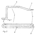
- FIG. 1 From the side view shown in Fig. 1 is the shape of a supporting strut 1 according to the invention, the spatial shape of the Protective grid intended to recognize.
- Protective grating comprises a plurality of support struts 1 in FIG usually arranged at the same angle radially to each other and Grid rings attached to them. It consists, as can be seen from FIG. 2, from a hairpin-like curved closed wire loop, the ends of the wire in the region of the parallel course of the two wire legs are butt welded together. The Joint is indicated by a weld 2.
- the Wire loop has a long, dull angled leg. 3 and a short, perpendicular to the long leg. 1 Angled leg 4, the end again at right angles angled, up.
- an eyelet 5 In the protective grille are the eyelets. 5 consequently on an outer circle. It will be with them Protective grid on a wall, which has an opening for the fan has attached.
- the long, dull-angled leg 3 is at his free end one more time angled, this short one Angled part 6 runs parallel to the eyelet 5.
- Be hairpin-shaped end is reduced in cross-section, so that the Support strut 1, as shown in FIG. 2, at this inner end a flattened eyelet 7, d. H.
- the perpendicular to the through the Wire loop formed plane measured thickness of the wire is on this end less than in its remaining course.
- the flattened eyelets 7 lie on an inner circle of the Protection grid. At you will be the fan, for example with his Stator bush or its end shield, attached.
Landscapes
- Engineering & Computer Science (AREA)
- Mechanical Engineering (AREA)
- General Engineering & Computer Science (AREA)
- Structures Of Non-Positive Displacement Pumps (AREA)
- Respiratory Apparatuses And Protective Means (AREA)
- Compressor (AREA)
Abstract
Description
- Fig. 1
- die Seitenansicht der erfindungsgemäßen Tragstrebe und
- Fig. 2
- die Draufsicht auf diese Tragstrebe.
- 1
- Tragstrebe
- 2
- Schweißnaht
- 3
- Stumpf abgewinkelter Schenkel
- 4
- Rechtwinklig abgewinkelter Schenkel
- 5
- Öse
- 6
- Abgewinkelter Teil
- 7
- Abgeflachte Öse
- 8
- Ebene Fläche
Claims (11)
- Schutzgitter für Lüfter, bestehend aus im wesentlichen radial angeordneten Tragstreben (1), an denen Gitterringe in der Regel konzentrisch zueinander befestigt sind, wobei die Tragstreben (1) aus ggf. abgewinkelten Drahtschlaufen bestehen, und zumindest bei einem Teil der Tragstreben (1) an deren innerem Ende mindestens eine ebene Fläche zur Befestigung des Lüfters vorgesehen ist,
dadurch gekennzeichnet, dass zumindest die mit dem Lüfter verbindbaren Tragstreben (1) aus einer geschlossenen, auch an ihrem inneren Ende U-förmig gebogenen Drahtschlaufe bestehen, so dass beide Enden (5, 7) der Tragstreben (1) haarnadelartig ausgebildet sind, und dass zumindest das innere Ende (7) der Tragstreben (1) abgeflacht ist. - Schutzgitter nach Anspruch 1,
dadurch gekennzeichnet, dass der Querschnitt der beiden parallel verlaufenden Schenkel der Tragstrcbe (1) an ihrem jeweils abgeflachten Ende (7) gleich dem Ausgangsquerschnitt der Schenkel der Tragstrebe (1) ist. - Schutzgitter nach Anspruch 1,
dadurch gekennzeichnet, dass der Querschnitt der beiden parallel verlaufenden Schenkel der Tragstrebe (1) an ihrem jeweils abgeflachten Ende (7) kleiner ist als der Ausgangsquerschnitt der Schenkel der Tragstrebe (1). - Schutzgitter nach Anspruch 3,
dadurch gekennzeichnet, dass die Abflachung des bzw. der Enden (7) der Tragstrebe (1) durch eine einseitige Reduzierung des Querschnitts des Drahts der Drahtschlaufe auf der dem Lüfter zugewandten Seite des Drahts gebildet wird. - Schutzgitter nach Anspruch 3,
dadurch gekennzeichnet, dass die Abflachung durch eine beidseitige Reduzierung des Querschnitts des Drahtes gebildet wird. - Schutzgitter nach Anspruch 1 bis 5,
dadurch gekennzeichnet, dass zumindest das innere abgeflachte Ende (7) der Tragstrebe (1) in der Draufsicht cine rechteckige Form aufweist. - Verfahren zur Herstellung eines Schutzgitters für Lüfter, das aus im wesentlichen radial angeordneten, ggf. mehrfach abgewinkelten Tragstreben (1) besteht, die aus gestrecktem Draht zu länglichen Schlaufen gebogen werden, bevor an ihnen in der Regel konzentrisch zueinander angeordnete Gitterringe befestigt werden, wobei zumindest bei einem Teil der Tragstreben (1) jeweils an deren innerem Ende mindestens eine ebene Fläche zur Verbindung mit dem Lüfter angebracht wird,
dadurch gekennzeichnet, dass zumindest die den Lüfter aufnehmenden Tragstreben (1) in Form einer geschlossenen Schlaufe gebogen und die beiden Drahtenden stumpf aneinanderstoßend miteinander verbunden werden, so dass beide Enden (5, 7) der Drahtschlaufe eine haarnadelartige Form aufweisen, und dass zumindest das nach innen weisende haarnadelartig gebogene Ende (7) dieser Tragstreben (1) im Bereich ihrer Verbindung mit dem Lüfter abgeflacht wird. - Verfahren nach Anspruch 7,
dadurch gekennzeichnet, dass das Abflachen des bzw. der Enden der Tragstreben (1) durch eine spanende Bearbeitung, beispielsweise Fräsen oder Schleifen, erfolgt. - Verfahren nach Anspruch 7,
dadurch gekennzeichnet, dass das Abflachen des bzw. der Enden der Tragstreben (1) durch eine spanlose Bearbeitung, beispielsweise Stauchen, erfolgt. - Verfahren nach Anspruch 9,
dadurch gekennzeichnet, dass bei der spanlosen Herstellung der Abflachung in diesem Bereich gleichzeitig eine Materialverdichtung erfolgt. - Verfahren nach Anspruch 7 bis 10,
dadurch gekennzeichnet, dass das Abflachen des bzw. der Enden (7) der Tragstreben (1) nach dem Befestigen der Gitterringe auf den Tragstreben (1) in einem einzigen Arbeitsgang erfolgt.
Priority Applications (1)
| Application Number | Priority Date | Filing Date | Title |
|---|---|---|---|
| SI200530018T SI1571350T1 (sl) | 2004-03-05 | 2005-03-04 | Zaščitna mreža za ventilator |
Applications Claiming Priority (2)
| Application Number | Priority Date | Filing Date | Title |
|---|---|---|---|
| DE102004011375 | 2004-03-05 | ||
| DE102004011375A DE102004011375A1 (de) | 2004-03-05 | 2004-03-05 | Schutzgitter für Lüfter und Verfahren zu seiner Herstellung |
Publications (3)
| Publication Number | Publication Date |
|---|---|
| EP1571350A1 true EP1571350A1 (de) | 2005-09-07 |
| EP1571350B1 EP1571350B1 (de) | 2007-02-21 |
| EP1571350B2 EP1571350B2 (de) | 2016-09-28 |
Family
ID=34745439
Family Applications (1)
| Application Number | Title | Priority Date | Filing Date |
|---|---|---|---|
| EP05004847.9A Expired - Lifetime EP1571350B2 (de) | 2004-03-05 | 2005-03-04 | Schutzgitter für Lüfter |
Country Status (5)
| Country | Link |
|---|---|
| EP (1) | EP1571350B2 (de) |
| AT (1) | ATE354732T1 (de) |
| DE (2) | DE102004011375A1 (de) |
| ES (1) | ES2282941T3 (de) |
| SI (1) | SI1571350T1 (de) |
Families Citing this family (2)
| Publication number | Priority date | Publication date | Assignee | Title |
|---|---|---|---|---|
| DE102015004019A1 (de) * | 2015-03-26 | 2016-09-29 | Uwe Stadtmüller | Schutzgitter; Verfahren zur Herstellung eines Schutzgitters für Lüfter |
| DE102016111516A1 (de) * | 2016-06-23 | 2017-12-28 | Ebm-Papst Mulfingen Gmbh & Co. Kg | Befestigungsstrebe für ein Lüfterschutzgitter |
Citations (4)
| Publication number | Priority date | Publication date | Assignee | Title |
|---|---|---|---|---|
| DE3210164A1 (de) * | 1982-03-19 | 1983-10-06 | Rohde & Schwarz | Vorrichtung zum befestigen eines mit einem schutzgitter abgedeckten luefters in einer gehaeusewand |
| DE3311660A1 (de) * | 1983-03-30 | 1984-10-04 | Siemens AG, 1000 Berlin und 8000 München | Axialventilator |
| US4836751A (en) * | 1988-07-25 | 1989-06-06 | Liu Ssu Liu | Detachable electric fan |
| DE4412193C1 (de) * | 1994-04-08 | 1995-08-31 | Guentner Gmbh Hans | Antriebsmotoranordnung für Luftkühlerventilatoren |
Family Cites Families (3)
| Publication number | Priority date | Publication date | Assignee | Title |
|---|---|---|---|---|
| DE7202133U (de) † | 1972-01-21 | 1972-04-13 | Gebr Trox Gmbh | Befestigungsarme fuer axialventilatoren |
| DE10003428B4 (de) * | 1999-01-26 | 2010-09-09 | Uwe Stadtmüller | Verfahren und Vorrichtung zum Verschweißen von Schutzgittern für durch einen elektrischen Außenläufermotor angetriebenen Lüfter |
| DE10111397B4 (de) * | 2001-03-09 | 2010-04-15 | Ebm-Papst Mulfingen Gmbh & Co. Kg | Schutzgitter für Ventilatoren |
-
2004
- 2004-03-05 DE DE102004011375A patent/DE102004011375A1/de not_active Withdrawn
-
2005
- 2005-03-04 SI SI200530018T patent/SI1571350T1/sl unknown
- 2005-03-04 ES ES05004847T patent/ES2282941T3/es not_active Expired - Lifetime
- 2005-03-04 DE DE502005000383T patent/DE502005000383D1/de not_active Expired - Lifetime
- 2005-03-04 AT AT05004847T patent/ATE354732T1/de not_active IP Right Cessation
- 2005-03-04 EP EP05004847.9A patent/EP1571350B2/de not_active Expired - Lifetime
Patent Citations (4)
| Publication number | Priority date | Publication date | Assignee | Title |
|---|---|---|---|---|
| DE3210164A1 (de) * | 1982-03-19 | 1983-10-06 | Rohde & Schwarz | Vorrichtung zum befestigen eines mit einem schutzgitter abgedeckten luefters in einer gehaeusewand |
| DE3311660A1 (de) * | 1983-03-30 | 1984-10-04 | Siemens AG, 1000 Berlin und 8000 München | Axialventilator |
| US4836751A (en) * | 1988-07-25 | 1989-06-06 | Liu Ssu Liu | Detachable electric fan |
| DE4412193C1 (de) * | 1994-04-08 | 1995-08-31 | Guentner Gmbh Hans | Antriebsmotoranordnung für Luftkühlerventilatoren |
Also Published As
| Publication number | Publication date |
|---|---|
| DE502005000383D1 (de) | 2007-04-05 |
| DE102004011375A1 (de) | 2005-09-22 |
| ES2282941T3 (es) | 2007-10-16 |
| EP1571350B1 (de) | 2007-02-21 |
| ATE354732T1 (de) | 2007-03-15 |
| EP1571350B2 (de) | 2016-09-28 |
| SI1571350T1 (sl) | 2007-08-31 |
Similar Documents
| Publication | Publication Date | Title |
|---|---|---|
| DE60312971T2 (de) | Anstauchbares befestigungselement mit optimierten verriegelungsnuten und scheiteln und verfahren zur ausführung desselben | |
| EP1479842B1 (de) | Hohlprofil | |
| DE602004012378T2 (de) | Speiche für Fahrradrad und Fahrradrad eine solche Speiche enthaltend sowie Herstellverfahren für eine solche Speiche | |
| DE2827188C2 (de) | Bohrlochsieb | |
| DE102015004019A1 (de) | Schutzgitter; Verfahren zur Herstellung eines Schutzgitters für Lüfter | |
| DE4234116A1 (de) | Schwingungsisolationsvorrichtung mit einer tragvorrichtung | |
| DE102013224380A1 (de) | Transversales einrastendes Kabelkanalteilstück, Kabelkanal mit solchen Teilstücken und Herstellungsverfahren | |
| CH638859A5 (de) | Geruest mit rohrstaendern und doppelgelaendern. | |
| DE2230276A1 (de) | Zwischen- und endmuffen fuer seile und litzen | |
| DE202015002378U1 (de) | Schutzgitter | |
| EP2133574A2 (de) | Räumliches Schutzgitter für Axiallüfter und Verfahren zur Herstellung des Schutzgitters | |
| EP1339993A1 (de) | Bundbuchse sowie verfahren zur herstellung einer solchen | |
| DE3047820C2 (de) | Verfahren zur Herstellung eines Sicherungselementes zum axialen Festlegen von Bolzen, Wellen oder dergleichen | |
| EP2167895A1 (de) | Wärmetauscher | |
| DE4328441A1 (de) | Seitenaufprallschutz in Form eines an der Tür eines Kraftfahrzeuges befestigbaren Profilgliedes sowie Verfahren zur Herstellung des Profilgliedes | |
| EP1571350B1 (de) | Schutzgitter für Lüfter | |
| EP1504190B1 (de) | Spirale einer stroe mungsmaschine | |
| EP3658770A1 (de) | Windenergieanlagen-stahlturmringsegment und verfahren | |
| EP0853990B1 (de) | Vorrichtung zum Durchsetzfügen von Blechteilen | |
| DE1243472B (de) | Flachzylindrischer, huelsenfoermiger Seilklemmrohling zur Herstellung einer Seiklemme | |
| EP0531879A1 (de) | Sägebandring und Verfahren zu seiner Herstellung | |
| WO2006111197A1 (de) | Doppelsträngige abgasanlage | |
| DE202017103877U1 (de) | Verbindungsanker sowie Beton-Sandwich-Platte mit derartigen Verbindungsankern | |
| WO2003038240A1 (de) | Sicherungsvorrichtung für laufschaufeln axial durchströmter turbomaschinen | |
| AT368583B (de) | Metallmast und verfahren zu seiner herstellung |
Legal Events
| Date | Code | Title | Description |
|---|---|---|---|
| PUAI | Public reference made under article 153(3) epc to a published international application that has entered the european phase |
Free format text: ORIGINAL CODE: 0009012 |
|
| AK | Designated contracting states |
Kind code of ref document: A1 Designated state(s): AT BE BG CH CY CZ DE DK EE ES FI FR GB GR HU IE IS IT LI LT LU MC NL PL PT RO SE SI SK TR |
|
| AX | Request for extension of the european patent |
Extension state: AL BA HR LV MK YU |
|
| 17P | Request for examination filed |
Effective date: 20051208 |
|
| AKX | Designation fees paid |
Designated state(s): AT BE BG CH CY CZ DE DK EE ES FI FR GB GR HU IE IS IT LI LT LU MC NL PL PT RO SE SI SK TR |
|
| GRAP | Despatch of communication of intention to grant a patent |
Free format text: ORIGINAL CODE: EPIDOSNIGR1 |
|
| GRAS | Grant fee paid |
Free format text: ORIGINAL CODE: EPIDOSNIGR3 |
|
| GRAA | (expected) grant |
Free format text: ORIGINAL CODE: 0009210 |
|
| AK | Designated contracting states |
Kind code of ref document: B1 Designated state(s): AT BE BG CH CY CZ DE DK EE ES FI FR GB GR HU IE IS IT LI LT LU MC NL PL PT RO SE SI SK TR |
|
| PG25 | Lapsed in a contracting state [announced via postgrant information from national office to epo] |
Ref country code: DK Free format text: LAPSE BECAUSE OF FAILURE TO SUBMIT A TRANSLATION OF THE DESCRIPTION OR TO PAY THE FEE WITHIN THE PRESCRIBED TIME-LIMIT Effective date: 20070221 Ref country code: FI Free format text: LAPSE BECAUSE OF FAILURE TO SUBMIT A TRANSLATION OF THE DESCRIPTION OR TO PAY THE FEE WITHIN THE PRESCRIBED TIME-LIMIT Effective date: 20070221 Ref country code: IE Free format text: LAPSE BECAUSE OF FAILURE TO SUBMIT A TRANSLATION OF THE DESCRIPTION OR TO PAY THE FEE WITHIN THE PRESCRIBED TIME-LIMIT Effective date: 20070221 Ref country code: NL Free format text: LAPSE BECAUSE OF FAILURE TO SUBMIT A TRANSLATION OF THE DESCRIPTION OR TO PAY THE FEE WITHIN THE PRESCRIBED TIME-LIMIT Effective date: 20070221 Ref country code: PL Free format text: LAPSE BECAUSE OF FAILURE TO SUBMIT A TRANSLATION OF THE DESCRIPTION OR TO PAY THE FEE WITHIN THE PRESCRIBED TIME-LIMIT Effective date: 20070221 |
|
| REG | Reference to a national code |
Ref country code: GB Ref legal event code: FG4D Free format text: NOT ENGLISH |
|
| REG | Reference to a national code |
Ref country code: CH Ref legal event code: EP |
|
| REF | Corresponds to: |
Ref document number: 502005000383 Country of ref document: DE Date of ref document: 20070405 Kind code of ref document: P |
|
| REG | Reference to a national code |
Ref country code: IE Ref legal event code: FG4D Free format text: LANGUAGE OF EP DOCUMENT: GERMAN |
|
| PGFP | Annual fee paid to national office [announced via postgrant information from national office to epo] |
Ref country code: RO Payment date: 20070518 Year of fee payment: 3 |
|
| PG25 | Lapsed in a contracting state [announced via postgrant information from national office to epo] |
Ref country code: SE Free format text: LAPSE BECAUSE OF FAILURE TO SUBMIT A TRANSLATION OF THE DESCRIPTION OR TO PAY THE FEE WITHIN THE PRESCRIBED TIME-LIMIT Effective date: 20070521 |
|
| PGFP | Annual fee paid to national office [announced via postgrant information from national office to epo] |
Ref country code: BG Payment date: 20070521 Year of fee payment: 3 Ref country code: ES Payment date: 20070521 Year of fee payment: 3 Ref country code: SI Payment date: 20070521 Year of fee payment: 3 |
|
| PG25 | Lapsed in a contracting state [announced via postgrant information from national office to epo] |
Ref country code: IS Free format text: LAPSE BECAUSE OF FAILURE TO SUBMIT A TRANSLATION OF THE DESCRIPTION OR TO PAY THE FEE WITHIN THE PRESCRIBED TIME-LIMIT Effective date: 20070621 |
|
| REG | Reference to a national code |
Ref country code: RO Ref legal event code: EPE |
|
| PG25 | Lapsed in a contracting state [announced via postgrant information from national office to epo] |
Ref country code: PT Free format text: LAPSE BECAUSE OF FAILURE TO SUBMIT A TRANSLATION OF THE DESCRIPTION OR TO PAY THE FEE WITHIN THE PRESCRIBED TIME-LIMIT Effective date: 20070723 |
|
| NLV1 | Nl: lapsed or annulled due to failure to fulfill the requirements of art. 29p and 29m of the patents act | ||
| ET | Fr: translation filed | ||
| GBV | Gb: ep patent (uk) treated as always having been void in accordance with gb section 77(7)/1977 [no translation filed] |
Effective date: 20070221 |
|
| REG | Reference to a national code |
Ref country code: IE Ref legal event code: FD4D |
|
| REG | Reference to a national code |
Ref country code: ES Ref legal event code: FG2A Ref document number: 2282941 Country of ref document: ES Kind code of ref document: T3 |
|
| PG25 | Lapsed in a contracting state [announced via postgrant information from national office to epo] |
Ref country code: SK Free format text: LAPSE BECAUSE OF FAILURE TO SUBMIT A TRANSLATION OF THE DESCRIPTION OR TO PAY THE FEE WITHIN THE PRESCRIBED TIME-LIMIT Effective date: 20070221 Ref country code: GB Free format text: LAPSE BECAUSE OF FAILURE TO SUBMIT A TRANSLATION OF THE DESCRIPTION OR TO PAY THE FEE WITHIN THE PRESCRIBED TIME-LIMIT Effective date: 20070221 |
|
| PLBI | Opposition filed |
Free format text: ORIGINAL CODE: 0009260 |
|
| PLAX | Notice of opposition and request to file observation + time limit sent |
Free format text: ORIGINAL CODE: EPIDOSNOBS2 |
|
| BERE | Be: lapsed |
Owner name: STADTMULLER, UWE Effective date: 20070331 |
|
| 26 | Opposition filed |
Opponent name: RUDOLF HARTL GMBH Effective date: 20071120 |
|
| PG25 | Lapsed in a contracting state [announced via postgrant information from national office to epo] |
Ref country code: BE Free format text: LAPSE BECAUSE OF NON-PAYMENT OF DUE FEES Effective date: 20070331 Ref country code: CZ Free format text: LAPSE BECAUSE OF FAILURE TO SUBMIT A TRANSLATION OF THE DESCRIPTION OR TO PAY THE FEE WITHIN THE PRESCRIBED TIME-LIMIT Effective date: 20070221 |
|
| PG25 | Lapsed in a contracting state [announced via postgrant information from national office to epo] |
Ref country code: MC Free format text: LAPSE BECAUSE OF NON-PAYMENT OF DUE FEES Effective date: 20070331 |
|
| REG | Reference to a national code |
Ref country code: HU Ref legal event code: AG4A Ref document number: E002443 Country of ref document: HU |
|
| PG25 | Lapsed in a contracting state [announced via postgrant information from national office to epo] |
Ref country code: LT Free format text: LAPSE BECAUSE OF FAILURE TO SUBMIT A TRANSLATION OF THE DESCRIPTION OR TO PAY THE FEE WITHIN THE PRESCRIBED TIME-LIMIT Effective date: 20070221 |
|
| PG25 | Lapsed in a contracting state [announced via postgrant information from national office to epo] |
Ref country code: GR Free format text: LAPSE BECAUSE OF FAILURE TO SUBMIT A TRANSLATION OF THE DESCRIPTION OR TO PAY THE FEE WITHIN THE PRESCRIBED TIME-LIMIT Effective date: 20070522 |
|
| PGFP | Annual fee paid to national office [announced via postgrant information from national office to epo] |
Ref country code: FR Payment date: 20070524 Year of fee payment: 3 |
|
| PLAF | Information modified related to communication of a notice of opposition and request to file observations + time limit |
Free format text: ORIGINAL CODE: EPIDOSCOBS2 |
|
| PG25 | Lapsed in a contracting state [announced via postgrant information from national office to epo] |
Ref country code: AT Free format text: LAPSE BECAUSE OF NON-PAYMENT OF DUE FEES Effective date: 20070304 |
|
| PLBB | Reply of patent proprietor to notice(s) of opposition received |
Free format text: ORIGINAL CODE: EPIDOSNOBS3 |
|
| REG | Reference to a national code |
Ref country code: SI Ref legal event code: KO00 Effective date: 20081119 |
|
| PG25 | Lapsed in a contracting state [announced via postgrant information from national office to epo] |
Ref country code: EE Free format text: LAPSE BECAUSE OF FAILURE TO SUBMIT A TRANSLATION OF THE DESCRIPTION OR TO PAY THE FEE WITHIN THE PRESCRIBED TIME-LIMIT Effective date: 20070221 |
|
| PG25 | Lapsed in a contracting state [announced via postgrant information from national office to epo] |
Ref country code: SI Free format text: LAPSE BECAUSE OF NON-PAYMENT OF DUE FEES Effective date: 20080305 |
|
| REG | Reference to a national code |
Ref country code: ES Ref legal event code: FD2A Effective date: 20080305 |
|
| PG25 | Lapsed in a contracting state [announced via postgrant information from national office to epo] |
Ref country code: RO Free format text: LAPSE BECAUSE OF NON-PAYMENT OF DUE FEES Effective date: 20080304 Ref country code: CY Free format text: LAPSE BECAUSE OF FAILURE TO SUBMIT A TRANSLATION OF THE DESCRIPTION OR TO PAY THE FEE WITHIN THE PRESCRIBED TIME-LIMIT Effective date: 20070221 Ref country code: ES Free format text: LAPSE BECAUSE OF NON-PAYMENT OF DUE FEES Effective date: 20080305 |
|
| PG25 | Lapsed in a contracting state [announced via postgrant information from national office to epo] |
Ref country code: LU Free format text: LAPSE BECAUSE OF NON-PAYMENT OF DUE FEES Effective date: 20070304 |
|
| PG25 | Lapsed in a contracting state [announced via postgrant information from national office to epo] |
Ref country code: TR Free format text: LAPSE BECAUSE OF FAILURE TO SUBMIT A TRANSLATION OF THE DESCRIPTION OR TO PAY THE FEE WITHIN THE PRESCRIBED TIME-LIMIT Effective date: 20070221 |
|
| REG | Reference to a national code |
Ref country code: CH Ref legal event code: PL |
|
| PG25 | Lapsed in a contracting state [announced via postgrant information from national office to epo] |
Ref country code: LI Free format text: LAPSE BECAUSE OF NON-PAYMENT OF DUE FEES Effective date: 20090331 Ref country code: CH Free format text: LAPSE BECAUSE OF NON-PAYMENT OF DUE FEES Effective date: 20090331 |
|
| PGFP | Annual fee paid to national office [announced via postgrant information from national office to epo] |
Ref country code: HU Payment date: 20100316 Year of fee payment: 6 |
|
| PG25 | Lapsed in a contracting state [announced via postgrant information from national office to epo] |
Ref country code: BG Free format text: LAPSE BECAUSE OF NON-PAYMENT OF DUE FEES Effective date: 20080331 |
|
| PLAB | Opposition data, opponent's data or that of the opponent's representative modified |
Free format text: ORIGINAL CODE: 0009299OPPO |
|
| REG | Reference to a national code |
Ref country code: FR Ref legal event code: ST Effective date: 20111202 |
|
| R26 | Opposition filed (corrected) |
Opponent name: RUDOLF HARTL GMBH Effective date: 20071120 |
|
| PG25 | Lapsed in a contracting state [announced via postgrant information from national office to epo] |
Ref country code: FR Free format text: LAPSE BECAUSE OF NON-PAYMENT OF DUE FEES Effective date: 20080331 Ref country code: HU Free format text: LAPSE BECAUSE OF NON-PAYMENT OF DUE FEES Effective date: 20110305 |
|
| PLAB | Opposition data, opponent's data or that of the opponent's representative modified |
Free format text: ORIGINAL CODE: 0009299OPPO |
|
| PLAY | Examination report in opposition despatched + time limit |
Free format text: ORIGINAL CODE: EPIDOSNORE2 |
|
| RAP4 | Party data changed (patent owner data changed or rights of a patent transferred) |
Owner name: STADTMUELLER, UWE |
|
| RIN2 | Information on inventor provided after grant (corrected) |
Inventor name: STADTMUELLER, UWE |
|
| R26 | Opposition filed (corrected) |
Opponent name: D-LS GMBH PROJEKTE & BETEILIGUNGEN Effective date: 20071120 |
|
| PLBC | Reply to examination report in opposition received |
Free format text: ORIGINAL CODE: EPIDOSNORE3 |
|
| PLBP | Opposition withdrawn |
Free format text: ORIGINAL CODE: 0009264 |
|
| PLAY | Examination report in opposition despatched + time limit |
Free format text: ORIGINAL CODE: EPIDOSNORE2 |
|
| PLBC | Reply to examination report in opposition received |
Free format text: ORIGINAL CODE: EPIDOSNORE3 |
|
| REG | Reference to a national code |
Ref country code: DE Ref legal event code: R082 Ref document number: 502005000383 Country of ref document: DE Representative=s name: PATENTANWAELTE SCHUSTER, MUELLER & PARTNER MBB, DE |
|
| PUAH | Patent maintained in amended form |
Free format text: ORIGINAL CODE: 0009272 |
|
| STAA | Information on the status of an ep patent application or granted ep patent |
Free format text: STATUS: PATENT MAINTAINED AS AMENDED |
|
| 27A | Patent maintained in amended form |
Effective date: 20160928 |
|
| AK | Designated contracting states |
Kind code of ref document: B2 Designated state(s): AT BE BG CH CY CZ DE DK EE ES FI FR GB GR HU IE IS IT LI LT LU MC NL PL PT RO SE SI SK TR |
|
| RAP2 | Party data changed (patent owner data changed or rights of a patent transferred) |
Owner name: STADTMUELLER, UWE |
|
| REG | Reference to a national code |
Ref country code: DE Ref legal event code: R102 Ref document number: 502005000383 Country of ref document: DE |
|
| RIN2 | Information on inventor provided after grant (corrected) |
Inventor name: STADTMUELLER, UWE |
|
| PGFP | Annual fee paid to national office [announced via postgrant information from national office to epo] |
Ref country code: DE Payment date: 20170530 Year of fee payment: 13 |
|
| PGFP | Annual fee paid to national office [announced via postgrant information from national office to epo] |
Ref country code: IT Payment date: 20170323 Year of fee payment: 13 |
|
| REG | Reference to a national code |
Ref country code: DE Ref legal event code: R119 Ref document number: 502005000383 Country of ref document: DE |
|
| PG25 | Lapsed in a contracting state [announced via postgrant information from national office to epo] |
Ref country code: DE Free format text: LAPSE BECAUSE OF NON-PAYMENT OF DUE FEES Effective date: 20181002 |
|
| PG25 | Lapsed in a contracting state [announced via postgrant information from national office to epo] |
Ref country code: IT Free format text: LAPSE BECAUSE OF NON-PAYMENT OF DUE FEES Effective date: 20180304 |