EP1479842B1 - Hohlprofil - Google Patents
Hohlprofil Download PDFInfo
- Publication number
- EP1479842B1 EP1479842B1 EP04100278A EP04100278A EP1479842B1 EP 1479842 B1 EP1479842 B1 EP 1479842B1 EP 04100278 A EP04100278 A EP 04100278A EP 04100278 A EP04100278 A EP 04100278A EP 1479842 B1 EP1479842 B1 EP 1479842B1
- Authority
- EP
- European Patent Office
- Prior art keywords
- bead
- corrugation
- stiffening
- depth
- hollow section
- Prior art date
- Legal status (The legal status is an assumption and is not a legal conclusion. Google has not performed a legal analysis and makes no representation as to the accuracy of the status listed.)
- Expired - Lifetime
Links
- 239000000463 material Substances 0.000 claims abstract description 61
- 238000000034 method Methods 0.000 claims abstract description 24
- 238000005452 bending Methods 0.000 claims description 14
- 239000002184 metal Substances 0.000 claims description 3
- 238000003825 pressing Methods 0.000 claims description 2
- 230000003014 reinforcing effect Effects 0.000 claims 1
- 238000007493 shaping process Methods 0.000 claims 1
- 238000004519 manufacturing process Methods 0.000 abstract description 8
- 238000010276 construction Methods 0.000 abstract 1
- 239000011324 bead Substances 0.000 description 146
- 238000005096 rolling process Methods 0.000 description 6
- 230000035882 stress Effects 0.000 description 6
- 230000003068 static effect Effects 0.000 description 5
- 229910000831 Steel Inorganic materials 0.000 description 3
- 238000013461 design Methods 0.000 description 3
- 238000003754 machining Methods 0.000 description 3
- 239000010959 steel Substances 0.000 description 3
- 230000000295 complement effect Effects 0.000 description 2
- 238000012545 processing Methods 0.000 description 2
- 230000000717 retained effect Effects 0.000 description 2
- 239000004698 Polyethylene Substances 0.000 description 1
- 238000009825 accumulation Methods 0.000 description 1
- 239000000969 carrier Substances 0.000 description 1
- 230000006835 compression Effects 0.000 description 1
- 238000007906 compression Methods 0.000 description 1
- 238000007596 consolidation process Methods 0.000 description 1
- 238000005336 cracking Methods 0.000 description 1
- 238000011161 development Methods 0.000 description 1
- 230000018109 developmental process Effects 0.000 description 1
- 230000009429 distress Effects 0.000 description 1
- 230000002349 favourable effect Effects 0.000 description 1
- 238000000465 moulding Methods 0.000 description 1
- -1 polyethylene Polymers 0.000 description 1
- 229920000573 polyethylene Polymers 0.000 description 1
- 230000000284 resting effect Effects 0.000 description 1
- 238000004513 sizing Methods 0.000 description 1
- 238000009423 ventilation Methods 0.000 description 1
Images


Classifications
-
- E—FIXED CONSTRUCTIONS
- E04—BUILDING
- E04C—STRUCTURAL ELEMENTS; BUILDING MATERIALS
- E04C3/00—Structural elongated elements designed for load-supporting
- E04C3/02—Joists; Girders, trusses, or trusslike structures, e.g. prefabricated; Lintels; Transoms; Braces
- E04C3/04—Joists; Girders, trusses, or trusslike structures, e.g. prefabricated; Lintels; Transoms; Braces of metal
- E04C3/06—Joists; Girders, trusses, or trusslike structures, e.g. prefabricated; Lintels; Transoms; Braces of metal with substantially solid, i.e. unapertured, web
- E04C3/07—Joists; Girders, trusses, or trusslike structures, e.g. prefabricated; Lintels; Transoms; Braces of metal with substantially solid, i.e. unapertured, web at least partly of bent or otherwise deformed strip- or sheet-like material
-
- E—FIXED CONSTRUCTIONS
- E04—BUILDING
- E04C—STRUCTURAL ELEMENTS; BUILDING MATERIALS
- E04C3/00—Structural elongated elements designed for load-supporting
- E04C3/02—Joists; Girders, trusses, or trusslike structures, e.g. prefabricated; Lintels; Transoms; Braces
- E04C3/04—Joists; Girders, trusses, or trusslike structures, e.g. prefabricated; Lintels; Transoms; Braces of metal
- E04C2003/0404—Joists; Girders, trusses, or trusslike structures, e.g. prefabricated; Lintels; Transoms; Braces of metal beams, girders, or joists characterised by cross-sectional aspects
- E04C2003/0408—Joists; Girders, trusses, or trusslike structures, e.g. prefabricated; Lintels; Transoms; Braces of metal beams, girders, or joists characterised by cross-sectional aspects characterised by assembly or the cross-section
- E04C2003/0421—Joists; Girders, trusses, or trusslike structures, e.g. prefabricated; Lintels; Transoms; Braces of metal beams, girders, or joists characterised by cross-sectional aspects characterised by assembly or the cross-section comprising one single unitary part
-
- E—FIXED CONSTRUCTIONS
- E04—BUILDING
- E04C—STRUCTURAL ELEMENTS; BUILDING MATERIALS
- E04C3/00—Structural elongated elements designed for load-supporting
- E04C3/02—Joists; Girders, trusses, or trusslike structures, e.g. prefabricated; Lintels; Transoms; Braces
- E04C3/04—Joists; Girders, trusses, or trusslike structures, e.g. prefabricated; Lintels; Transoms; Braces of metal
- E04C2003/0404—Joists; Girders, trusses, or trusslike structures, e.g. prefabricated; Lintels; Transoms; Braces of metal beams, girders, or joists characterised by cross-sectional aspects
- E04C2003/0426—Joists; Girders, trusses, or trusslike structures, e.g. prefabricated; Lintels; Transoms; Braces of metal beams, girders, or joists characterised by cross-sectional aspects characterised by material distribution in cross section
- E04C2003/043—Joists; Girders, trusses, or trusslike structures, e.g. prefabricated; Lintels; Transoms; Braces of metal beams, girders, or joists characterised by cross-sectional aspects characterised by material distribution in cross section the hollow cross-section comprising at least one enclosed cavity
-
- E—FIXED CONSTRUCTIONS
- E04—BUILDING
- E04C—STRUCTURAL ELEMENTS; BUILDING MATERIALS
- E04C3/00—Structural elongated elements designed for load-supporting
- E04C3/02—Joists; Girders, trusses, or trusslike structures, e.g. prefabricated; Lintels; Transoms; Braces
- E04C3/04—Joists; Girders, trusses, or trusslike structures, e.g. prefabricated; Lintels; Transoms; Braces of metal
- E04C2003/0404—Joists; Girders, trusses, or trusslike structures, e.g. prefabricated; Lintels; Transoms; Braces of metal beams, girders, or joists characterised by cross-sectional aspects
- E04C2003/0443—Joists; Girders, trusses, or trusslike structures, e.g. prefabricated; Lintels; Transoms; Braces of metal beams, girders, or joists characterised by cross-sectional aspects characterised by substantial shape of the cross-section
- E04C2003/0465—Joists; Girders, trusses, or trusslike structures, e.g. prefabricated; Lintels; Transoms; Braces of metal beams, girders, or joists characterised by cross-sectional aspects characterised by substantial shape of the cross-section square- or rectangular-shaped
-
- F—MECHANICAL ENGINEERING; LIGHTING; HEATING; WEAPONS; BLASTING
- F16—ENGINEERING ELEMENTS AND UNITS; GENERAL MEASURES FOR PRODUCING AND MAINTAINING EFFECTIVE FUNCTIONING OF MACHINES OR INSTALLATIONS; THERMAL INSULATION IN GENERAL
- F16B—DEVICES FOR FASTENING OR SECURING CONSTRUCTIONAL ELEMENTS OR MACHINE PARTS TOGETHER, e.g. NAILS, BOLTS, CIRCLIPS, CLAMPS, CLIPS OR WEDGES; JOINTS OR JOINTING
- F16B2200/00—Constructional details of connections not covered for in other groups of this subclass
- F16B2200/69—Redundant disconnection blocking means
-
- Y—GENERAL TAGGING OF NEW TECHNOLOGICAL DEVELOPMENTS; GENERAL TAGGING OF CROSS-SECTIONAL TECHNOLOGIES SPANNING OVER SEVERAL SECTIONS OF THE IPC; TECHNICAL SUBJECTS COVERED BY FORMER USPC CROSS-REFERENCE ART COLLECTIONS [XRACs] AND DIGESTS
- Y10—TECHNICAL SUBJECTS COVERED BY FORMER USPC
- Y10T—TECHNICAL SUBJECTS COVERED BY FORMER US CLASSIFICATION
- Y10T29/00—Metal working
- Y10T29/49—Method of mechanical manufacture
- Y10T29/49826—Assembling or joining
- Y10T29/49908—Joining by deforming
- Y10T29/49915—Overedge assembling of seated part
-
- Y—GENERAL TAGGING OF NEW TECHNOLOGICAL DEVELOPMENTS; GENERAL TAGGING OF CROSS-SECTIONAL TECHNOLOGIES SPANNING OVER SEVERAL SECTIONS OF THE IPC; TECHNICAL SUBJECTS COVERED BY FORMER USPC CROSS-REFERENCE ART COLLECTIONS [XRACs] AND DIGESTS
- Y10—TECHNICAL SUBJECTS COVERED BY FORMER USPC
- Y10T—TECHNICAL SUBJECTS COVERED BY FORMER US CLASSIFICATION
- Y10T428/00—Stock material or miscellaneous articles
- Y10T428/12—All metal or with adjacent metals
- Y10T428/12354—Nonplanar, uniform-thickness material having symmetrical channel shape or reverse fold [e.g., making acute angle, etc.]
-
- Y—GENERAL TAGGING OF NEW TECHNOLOGICAL DEVELOPMENTS; GENERAL TAGGING OF CROSS-SECTIONAL TECHNOLOGIES SPANNING OVER SEVERAL SECTIONS OF THE IPC; TECHNICAL SUBJECTS COVERED BY FORMER USPC CROSS-REFERENCE ART COLLECTIONS [XRACs] AND DIGESTS
- Y10—TECHNICAL SUBJECTS COVERED BY FORMER USPC
- Y10T—TECHNICAL SUBJECTS COVERED BY FORMER US CLASSIFICATION
- Y10T428/00—Stock material or miscellaneous articles
- Y10T428/12—All metal or with adjacent metals
- Y10T428/12361—All metal or with adjacent metals having aperture or cut
-
- Y—GENERAL TAGGING OF NEW TECHNOLOGICAL DEVELOPMENTS; GENERAL TAGGING OF CROSS-SECTIONAL TECHNOLOGIES SPANNING OVER SEVERAL SECTIONS OF THE IPC; TECHNICAL SUBJECTS COVERED BY FORMER USPC CROSS-REFERENCE ART COLLECTIONS [XRACs] AND DIGESTS
- Y10—TECHNICAL SUBJECTS COVERED BY FORMER USPC
- Y10T—TECHNICAL SUBJECTS COVERED BY FORMER US CLASSIFICATION
- Y10T428/00—Stock material or miscellaneous articles
- Y10T428/12—All metal or with adjacent metals
- Y10T428/12382—Defined configuration of both thickness and nonthickness surface or angle therebetween [e.g., rounded corners, etc.]
-
- Y—GENERAL TAGGING OF NEW TECHNOLOGICAL DEVELOPMENTS; GENERAL TAGGING OF CROSS-SECTIONAL TECHNOLOGIES SPANNING OVER SEVERAL SECTIONS OF THE IPC; TECHNICAL SUBJECTS COVERED BY FORMER USPC CROSS-REFERENCE ART COLLECTIONS [XRACs] AND DIGESTS
- Y10—TECHNICAL SUBJECTS COVERED BY FORMER USPC
- Y10T—TECHNICAL SUBJECTS COVERED BY FORMER US CLASSIFICATION
- Y10T428/00—Stock material or miscellaneous articles
- Y10T428/12—All metal or with adjacent metals
- Y10T428/1241—Nonplanar uniform thickness or nonlinear uniform diameter [e.g., L-shape]
Definitions
- the invention relates to a hollow profile, in particular a hollow profile for a mounting system, from a flat material. At least one side wall of the hollow profile at least one bead is formed on the outside thereof. The at least one bead has a bead bottom spaced apart from the outside of the hollow profile by a bead depth and two opposing bead walls, wherein the amount of the bead depth of the at least one bead is in the range of 0.5 to 2.0 times the material thickness of the flat material. Furthermore, the invention relates to the method for producing a profile with at least one bead.
- Hollow profiles made from a flat material have a low dead weight with good static values.
- Hollow profiles of a mounting system are in particular provided with beads for positioning and guiding attachment or attachment parts in which the attachment parts are guided.
- torsional stresses often act on the hollow profiles, which is why circumferentially closed profiles are preferred for static reasons.
- the deeper the depth of the sill the lower the torsional load that this profile can take on. It is therefore desirable to make the sill depth as low as possible.
- the measure of the inner bending radius of a sheet which is bent by 90 °, the measure of the material thickness of the sheet.
- the disadvantage here is that with a small bead depth, due to the required bending radii, can not realize perpendicular to the bead bottom, or perpendicular to the outside extending bead walls. If tighter bending radii than the material thickness of the flat material used, this leads to a compression of the flat material on the inside and to an extension of the sheet on the outside of the turn, which leads to cracking or to a reduction in the material strength.
- the EP 1 288 387 A1 shows a mounting rail with an elongate rail body of approximately C-shaped cross-section, which has on the outer contour of the side walls in the longitudinal direction extending groove-like depressions, wherein the amount of the depth of the groove-like depressions corresponds to about 0.8 times the wall thickness.
- the cross section of the recess normal to the longitudinal direction is formed substantially at right angles, wherein the bead walls are substantially rounded.
- the object of the invention is to provide a hollow profile of a flat material with a bead, wherein to ensure the acquisition of torsional stresses, the bead has a small bead depth, and wherein the bead ensures sufficient longitudinal and lateral guidance for a tether.
- the hollow profile should also be easy and inexpensive to produce.
- the bead walls of the bead are oriented substantially perpendicular to the bead bottom and are substantially planar, with the flat portion extending over a majority of the bead depth.
- a plain bearing z. B. be arranged in the bead from polyethylene.
- Such plain bearings are provided for example in the arrangement of resting on the hollow profile components, which z. B. are movably mounted along its longitudinal extent to reduce any stresses in this component.
- Such components are, for example, carriers or cable strands, such as pipelines or ventilation ducts.
- the bead depth of the at least one bead is less than 1.5 times that of the material thickness of the flat material.
- the static n values of the hollow profile according to the invention are largely retained and the defined guidance of a connecting part on the hollow profile is nevertheless ensured.
- At least one bead is arranged on each side wall of the hollow profile.
- all beads have substantially the same configuration and thus the same bead depth and bead width.
- a great flexibility in the use of the hollow profile is ensured with a similar design of all arranged beads.
- the bead bottom of the at least one bead preferably extends axially parallel to the corresponding cross-sectional axis of the hollow profile.
- a rectangular hollow profile with four side walls and one, formed in each side wall bead, preferably all bead bottom axis parallel to the corresponding cross-sectional axes.
- the beads preferably extend over the entire length of the hollow profile parallel to its longitudinal axis.
- mounting holes are formed in the bead bottom of the at least one bead. These mounting holes are used, for example, to carry out a fastening means for fixing a connecting part to the hollow profile according to the invention.
- the mounting holes are preferably matched to the nature of the fastener and z. B. have a round or rectangular cross-section.
- the sheet for producing the hollow profile is a metal sheet, which is preferably processed in a roll rolling / bending process.
- Sheet metal as a flat material can be simple and inexpensive to process. With the roll rolling / bending process, a large number of profiles can be produced.
- other production methods can be used, such as a stamping / bending process.
- the inner bend radius can essentially correspond to the dimension of the material thickness of the flat material.
- the material strength of the flat material in the region of the bends is only marginally reduced.
- the bead bottom is pushed back against the profiling of the bead until the desired final depth of the bead is reached.
- the bead forms a dovetail shape in cross-section. The width of the bead in the plane of the corresponding side wall is smaller than the desired width of the finished bead.
- the projecting into the cross-section material is then pushed away laterally, so that after this machining operation, the bead has the desired width.
- this can flow into the free space located in the inner radius.
- the flow of the material leads to statically favorable material hardening and accumulation of material in the areas that are otherwise exposed to the greatest negative stresses under load.
- the flat material is brought into the desired profile shape. All processing steps for the production of the bead are preferably carried out in a roll rolling process.
- the material stress does not take place as a superposition of the stresses in the main bending area, but shifts into the bead walls. There, the stresses can spread relatively freely and the material is not damaged in these areas.
- well-defined in the width and depth well defined perpendicular to the bead bottom bead wall sections can be realized despite small depth of the bead, which serve as longitudinal and lateral guidance for the matched to the configuration of the bead molding and Anbindemaschine.
- the bead bottom is rectified.
- the tolerances are limited to a tolerable level.
- the bead is laterally and below z. B. supported by rollers or a support in pushing away the projecting into the bead material, so that can be dispensed with an additional messages of the bottom bead.
- the method preferably comprises the integral connection of the free longitudinal edges of the bent sheet material to form a hollow profile.
- the longitudinal edges are preferably connected to each other over their entire length, for example, welded together, soldered or glued.
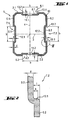
- FIG Fig. 1 A cross section through a hollow profile according to the invention is shown in FIG Fig. 1 shown.
- the hollow profile 1 has a substantially rectangular cross-section and has a first pair of side walls 2.1 and 2.2 extending parallel to one another and to a cross-sectional axis 3 and a second pair of side walls 5.1 and 5.2 extending parallel to one another and to a cross-sectional axis 4.
- the hollow profile 1 has a smaller dimension in the direction of the cross-sectional axis 3 than in the direction of the cross-sectional axis 4.
- the hollow profile 1 is made of a steel sheet in a roll rolling / bending process and has a uniform material thickness d. The machined and profiled steel sheet is connected by means of a weld 10 to the hollow profile 1 cohesively.
- each extending in the longitudinal direction L of the hollow section 1 bead 6.1, or 6.2 and on the side walls 5.1 and 5.2 each extending in the longitudinal direction L of the hollow section 1 bead 7.1, and 7.2 as longitudinal and lateral guidance designed for tailored to the bead design form and Anbindemaschine.
- the beads 6.1, 6.2, 7.1 and 7.2 have the same dimensions in the width b and in the depth t. This allows the arrangement of these beads 6.1, 6.2, 7.1 and 7.2 coordinated Anbindewel along the entire longitudinal direction L of the hollow section 1 and on each side wall 2.1, 2.2, 5.1 or 5.2, which given a wide application of the hollow section 1, for example, as a mounting bracket in a mounting system is.
- Each bead is formed from a bead bottom 8.1, 8.2, 9.1 or 9.2 and a pair of bead walls 13.1 and 13.2.
- the bead bottom 8.1 of the bead 6.1 runs parallel to the plane of the side wall 2.1 and the bead bottom 8.2 of the bead 6.2 runs parallel to the plane of the side wall 2.2.
- the bead bottom 9.1 of the bead 7.1 runs parallel to the plane of the side wall 5.1 and the bead bottom 9.2 of the bead 7.2 runs parallel to the plane of the side wall 5.2.
- a mounting opening 11.1 or 11.2 for the passage of a fastening means along the cross-sectional axis 4 is respectively arranged in the bead bottom 8.1 and 8.2.
- a mounting opening 12.1 or 12.2 for the passage of a fastening means along the cross-sectional axis 3 is respectively arranged in the bead bottom 9.1 and 9.2.
- Fig. 2 shows an enlarged detail of the bead wall 13.1 according to the area II in Fig. 1 ,
- the depth t of the bead 7.2 corresponds to approximately 1.2 times the material thickness d of the Hollow profile 1.
- the bead wall 13.1 is aligned substantially perpendicular to the bottom of the bead 9.2 and has a flat or flat section h based on the depth t of about 70%.
- An attachment part arranged in the beading 7.2 is guided in the longitudinal direction L of the hollow profile 1 and in the direction of the bead walls 13.1 and 13.2.
- FIG. 3 A cross section through the hollow profile 1 according to the invention Fig. 1 with arranged Anbinde sculpture is in the Fig. 3 shown.
- the angle 21 is arranged as a first attachment part.
- the amount of the width W of the angle 21 is minimally smaller than the width b of the bead 6.1 formed.
- the angle 21 is guided by the configuration of the bead 6.1 along the side wall 2.1 and laterally parallel to the plane of the side wall 2.1 in the bead walls 13.1 and 13.2.
- the angle 21 is fixed to the hollow profile 1.
- the angle 26 is arranged as a further tether.
- the width V of the angle 26 is greater than the width b of the bead 7.2 formed.
- the leg 27 for bearing the angle 26 on the hollow profile 1 has a complementary design to the configuration of the bead. By means of the carriage bolt 28, the angle 26 is fixed to the hollow profile 1.
- the leg 27 of the angle 26 is in area with the bead walls in contact.
- a lateral load of the angle 26 for example in the direction of arrow 29 is formed in the region of the bead 7.2 no significant force component that can lift the angle 26 from the beading 7.2.
- a high, lateral force share can be taken.
- Fig. 4a to 4c show on the basis of three detailed representations of the process for producing a bead.
- the production of the bead will be explained below by means of a roll rolling process.
- a flat material 31 for example, a steel sheet
- a roller by means of a roller (not shown here), a bead 32 profiled with a depth T.
- the amount of depth T is greater than the desired final depth t, which should have the finished bead 32 formed.
- the inner bending radii R 1 and R 2 correspond approximately to the amount of the material thickness d of the flat material 31.
- the bead bottom 33 is pressed in the opposite direction to the first profiling or in the direction of the arrow 34 until the bead 32 reaches the desired final depth t having.
- the bead 32 forms a dovetail shape in cross-section.
- the clear width U of the bead 32 during this processing step is smaller than the width b formed, which is to have the bead 32 at the end of production.
- first calibrating roller 35 By means of a first calibrating roller 35, the material 36 projecting into the bead 32 is pushed away laterally, the material beginning to flow and solidifying in this region. Following or during the pushing away of the material 36, the bead bottom 33 is aligned by means of a straightening roller 37. Additionally, a second sizing roll 38 may also force the protruding material 39 sideways, thereby providing material consolidation in this turn region as well.
- the bead 32 produced by the method according to the invention has a large proportion of flat and perpendicular portions of the bead walls 40.1 and 40.2 which are oriented perpendicular to the bead bottom 33.
- a hollow profile was created from a flat material, which despite the arrangement of beads has high static values. Despite the small depth of the bead sufficient longitudinal and lateral guidance is ensured in the bead for arranged on the hollow profile attachment parts.
- the hollow profile is also simple and inexpensive to produce and has a low weight.
Landscapes
- Engineering & Computer Science (AREA)
- Architecture (AREA)
- Civil Engineering (AREA)
- Structural Engineering (AREA)
- Rod-Shaped Construction Members (AREA)
- Body Structure For Vehicles (AREA)
- External Artificial Organs (AREA)
- Panels For Use In Building Construction (AREA)
- Bending Of Plates, Rods, And Pipes (AREA)
- Artificial Filaments (AREA)
Description
- Die Erfindung betrifft ein Hohlprofil, insbesondere ein Hohlprofil für ein Montagesystem, aus einem Flachmaterial. An zumindest einer Seitenwand des Hohlprofils ist an dessen Aussenseite zumindest eine Sicke ausgebildet. Die zumindest eine Sicke weist einen zur Aussenseite des Hohlprofils um eine Sickentiefe beabstandeten Sickenboden und zwei gegenüberliegende Sickenwände auf, wobei der Betrag der Sickentiefe der zumindest einen Sicke im Bereich des 0.5- bis 2.0-fachen der Materialstärke des Flachmaterials liegt. Weiter betrifft die Erfindung das Verfahren zur Herstellung eines Profils mit zumindest einer Sicke.
- Aus einem Flachmaterial gefertigte Hohlprofile weisen ein geringes Eigengewicht bei guten statischen Werten auf. Zur Positionierung und Führung von Anbinde-, beziehungsweise Anbauteilen werden insbesondere Hohlprofile eines Montagesystems mit Sicken versehen, in denen die Anbindeteile geführt sind. Auf die Hohlprofile wirken infolge der daran angeschlossenen Elemente oftmals Torsionsbelastungen, weshalb im Umfang geschlossene Profile aus statischen Gründen bevorzugt sind. Je tiefer jedoch die Sickentiefe ist, desto geringer ist die Torsionsbelastung, die dieses Profil übernehmen kann. Es ist deshalb angestrebt, die Sickentiefe so gering wie möglich auszubilden.
- Standardmässig entspricht das Mass des inneren Biegeradius eines Bleches, welches um 90° gebogen wird, dem Mass der Materialstärke des Blechs. Nachteilig dabei ist, dass bei einer geringen Sickentiefe, bedingt durch die erforderlichen Biegeradien, sich keine senkrecht zum Sickenboden, beziehungsweise senkrecht zur Aussenseite verlaufende Sickenwände realisieren lassen. Werden engere Biegeradien als die Materialstärke des Flachmaterials verwendet, führt dies zu einer Stauchung des Flachmaterials auf der Innenseite und zu einer Streckung des Flachmaterials auf der Aussenseite der Abbiegung, was zu einer Rissbildung, beziehungsweise zu einer Verringerung der Materialfestigkeit führt.
- Um engere Biegeradien als das Mass der Materialstärke des Flachmaterials zu ermöglichen, ist es bekannt, auf der Position des Innenradius das Material vorzukerben. Dies führt jedoch zu einer Querschnittsverminderung des Materials und somit ebenfalls zu einer Verringerung der Materialfestigkeit.
- Bis anhin wurden bei Sicken mit einer geringen Tiefe diese Probleme umgangen, indem die Sickenwände in einem Winkel, z. B. in einem Winkel von 45°, zum Sickenboden nach aussen verlaufen. Wird ein Anbindeteil mit einer rechteckigen Anlagefläche seitlich belastet, ist bei dieser Ausgestaltung der Sicke nur ein Linienkontakt vorhanden, so dass die in Profillängsrichtung definierte Führung und Verdrehsicherheit des Anbindeteils nicht gewährleistet ist. Ist die Auflagefläche komplementär zur Sickenausgestaltung ausgebildet, entsteht bei einer seitlichen Belastung des Anbindeteils eine schräg zu Kraftrichtung verlaufende Kraftkomponente, die das Anbindeteil aus der Sicke heben kann.
- Die
EP 1 288 387 A1 zeigt eine Montageschiene mit einem länglichen Schienenkörper von etwa C-förmigem Querschnitt, die an der Aussenkontur der Seitenwände in Längsrichtung verlaufende nutenartige Vertiefungen aufweist, wobei der Betrag der Tiefe der nutenartigen Vertiefungen etwa dem 0.8-fachen der Wandstärke entspricht. Der Querschnitt der Vertiefung normal zur Längsrichtung ist im Wesentlichen rechtwinklig ausgebildet, wobei die Sickenwände im Wesentlichen gerundet verlaufen. - Aufgabe der Erfindung ist es, ein Hohlprofil aus einem Flachmaterial mit einer Sicke zu versehen, wobei zur Gewährleistung der Übernahme von Torsionsspannungen die Sicke eine geringe Sickentiefe aufweist, und wobei die Sicke eine ausreichende Längs- und Seitenführung für ein Anbindeteil gewährleistet. Das Hohlprofil soll zudem einfach und kostengünstig herstellbar sein.
- Die Aufgabe ist durch die Merkmale der unabhängigen Ansprüche gelöst. Vorteilhafte Weiterbildungen sind in den Unteransprüchen dargelegt.
- Gemäss der Erfindung sind die Sickenwände der Sicke im Wesentlichen senkrecht zu dem Sickenboden ausgerichtet und im Wesentlichen eben ausgebildet, wobei sich der ebene Abschnitt über einen Grossteil der Sickentiefe erstreckt.
- Durch diese Ausgestaltung der zumindest einen Sicke bleiben die statischen Eigenschaften eines aus einem Flachmaterial gefertigten Hohlprofils weitgehend erhalten und eine definierte Längs- und Seitenführung eines Anbinde-, beziehungsweise Anbauteils am Hohlprofil ist gewährleistet. Auf die Querschnittsabmessungen der Sicke abgestimmte Anbindeteile lassen sich im angeordneten Zustand am erfindungsgemässen Hohlprofil weder verdrehen noch seitlich, d. h. in Querrichtung zur Längsachse des Hohlprofils verschieben. Über die im Wesentlichen senkrecht zum Sickenboden ausgerichtete und im Wesentlichen eben ausgebildeten Sickenwände ist ein Flächenkontakt zwischen dem Anbindeteil und dem Hohlprofil gewährleistet, so dass gegenüber Sickenwänden, die in einem Winkel von weniger als 90° zum Sickenboden ausgerichtet sind, trotz der geringen Sickentiefe ein Vielfaches der Kraft übertragen werden kann. Zudem kann das Anbindeteil infolge einer seitlichen Belastung nicht aus der Sicke des erfindungsgemässen Hohlprofils gehoben werden.
- Anstelle oder zusätzlich zu diesem kann beispielsweise ein Gleitlager z. B. aus Polyethylen in der Sicke angeordnet werden. Solche Gleitlager werden beispielsweise bei der Anordnung von an dem Hohlprofil aufliegenden Bauteilen vorgesehen, welche z. B. entlang ihrer Längserstreckung beweglich gelagert sind um allfällige Spannungen in diesem Bauteil abzubauen. Solche Bauteile sind beispielsweise Träger oder Leitungsstränge, wie Rohrleitungen oder Lüftungskanäle.
- Vorzugsweise beträgt die Sickentiefe der zumindest einen Sicke weniger als das 1.5-fache der der Materialstärke des Flachmaterials. Mit diesen Sickentiefen bleiben die statische n Werte des erfindungsgemässen Hohlprofils weitgehend erhalten und die definierte Führung eines Anbindeteils am Hohlprofil ist trotzdem gewährleistet.
- Bevorzugt ist an jeder Seitenwand des Hohlprofils zumindest eine Sicke angeordnet. An einer Seitenwand eines Hohlprofils können auch mehrere Sicken nebeneinander vorgesehen werden. Vorzugsweise weisen alle Sicken im Wesentlichen die gleiche Ausgestaltung und somit die gleiche Sickentiefe und Sickenbreite auf. Insbesondere bei einem erfindungsgemässen Hohlprofil zur Verwendung in einem Montagesystem ist bei einer gleichartigen Ausgestaltung aller angeordneten Sicken eine grosse Flexibilität in der Verwendung des Hohlprofils gewährleistet.
- Der Sickenboden der zumindest einen Sicke verläuft vorzugsweise achsparallel zu der entsprechenden Querschnittsachse des Hohlprofils. Bei einem rechtwinkligen Hohlprofil mit vier Seitenwänden und jeweils einer, in jeder Seitenwand ausgebildeten Sicke, verlaufen bevorzugt alle Sickenboden achsparallel zu den entsprechenden Querschnittsachsen. Die Sicken verlaufen vorzugsweise über die ganze Länge des Hohlprofils parallel zu dessen Längsachse.
- Vorteilhafterweise sind im Sickenboden der zumindest einen Sicke Montageöffnungen ausgebildet. Diese Montageöffnungen dienen beispielsweise zur Durchführung eines Befestigungsmittels zur Fixierung eines Anbindeteils an dem erfindungsgemässen Hohlprofil. Die Montageöffnungen sind bevorzugt auf die Art des Befestigungsmittels abgestimmt und können z. B. einen runden oder rechteckigen Querschnitt aufweisen.
- Vorzugsweise ist das Flachmaterial zur Fertigung des Hohlprofils ein Metallblech, das bevorzugt in einem Rollwalz-/Biegeverfahren bearbeitet ist. Metallblech als Flachmaterial lässt sich einfach und kostengünstig verarbeiten. Mit dem Rollwalz-/Biegeverfahren lassen sich eine Vielzahl von Profilen fertigen. Neben dem Rollwalz-/Biegeverfahren können auch andere Herstellverfahren zur Anwendung kommen, wie beispielsweise ein Stanz-/Biegeverfahren.
- Das Verfahren zur Fertigung eines Profils, insbesondere zur Fertigung eines erfindungsgemässen Hohlprofils, aus einem Flachmaterial, das an zumindest einer Seitenwand des Profils an dessen Aussenseite zumindest eine Sicke aufweist, wobei die zumindest eine Sicke einen zur Aussenseite des Hohlprofils um eine Sickentiefe beabstandeten Sickenboden und zwei gegenüberliegende Sickenwände aufweist, umfasst die folgenden Verfahrensschritte:
- a) Profilieren der zumindest einen Sicke mit einer Tiefe, die grösser als die gewünschte Endtiefe der Sicke ist;
- b) Drücken des Sickenbodens in Gegenrichtung zur ersten Profilierung bis die Tiefe der Sicke im Wesentlichen der gewünschten Endtiefe der Sicke entspricht, wobei die zumindest eine Sicke im Querschnitt eine Schwalbenschwanz-Form ausbildet;
- c) Wegdrücken des in den Querschnitt der Sicke ragenden Materials, optional mittels einer Walze; und
- d) Biegen des Flachmaterials in die gewünschte Profilform.
- Da im ersten Verfahrensschritt die Sickentiefe grösser als die gewünschte Endtiefe der Sicke ausgebildet wird, kann der innere Biegeradius im Wesentlichen dem Mass der Materialstärke des Flachmaterials entsprechen. Dadurch verringert sich die Materialfestigkeit des Flachmaterials im Bereich der Abbiegungen nur unwesentlich. Anschliessend wird der Sickenboden entgegen der Profilierungsrichtung der Sicke zurückgedrückt, bis die gewünschte Endtiefe der Sicke erreicht ist. Bei diesem Bearbeitungsvorgang bildet die Sicke im Querschnitt eine Schwalbenschwanzform aus. Die Breite der Sicke in der Ebene der entsprechenden Seitenwand ist hierbei kleiner als die gewünschte Breite der fertigen Sicke. Das in den Querschnitt hineinragende Material wird anschliessend seitlich weggedrückt, so dass nach diesem Bearbeitungsvorgang die Sicke die gewünschte Breite aufweist. Beim Wegdrücken des überstehenden Materials kann dieses in den im Innenradius befindlichen Freiraum fliessen. Durch das Fliessen des Materials kommt es zu statisch günstigen Materialverfestigungen und Materialanhäufungen in den Bereichen, die sonst unter Belastung den grössten negativen Beanspruchungen ausgesetzt sind. Im Anschluss wird das Flachmaterial in die gewünschte Profilform gebracht. Sämtliche Bearbeitungsschritte zur Fertigung der Sicke erfolgen vorzugsweise in einem Rollwalzverfahren.
- Die Materialbeanspruchung findet nicht als Überlagerung der Spannungen im Hauptbiegebereich statt, sondern verlagert sich in die Sickenwände. Dort können sich die Spannungen relativ frei verteilen und das Material wird nicht in diesen Bereichen geschädigt. Zudem können trotz geringer Sickentiefe masslich in der Breite und Tiefe genau definierte senkrecht zum Sickenboden ausgerichtete Sickenwandabschnitte realisiert werden, die als Längs- und Seitenführung für die, auf die Ausgestaltung der Sicke abgestimmte Form- und Anbindeteile dienen.
- Vorzugsweise wird nach dem Wegdrücken des in den Querschnitt der Sicke ragenden Materials in einem weiteren Verfahrensschritt der Sickenboden nachgerichtet. Je nach Ausgestaltung der Vorrichtung zur Fertigung der Sicken entstehen bei den einzelnen Verfahrensschritten grosse Abweichungen in den Abmessungen, die ausserhalb der gewünschten Toleranzen liegen. Mittels des Nachrichtens des Sickenbodens werden die Toleranzen auf ein tolerierbares Mass begrenzt. In einer alternativen Ausführungsform des erfindungsgemässen Verfahrens wird die Sicke seitlich und unterhalb z. B. durch Walzen oder ein Auflager beim Wegdrücken des in die Sicke hineinragenden Materials gestützt, so dass auf ein zusätzliches Nachrichten des Sickenbodens verzichtet werden kann.
- Bevorzugt umfasst das Verfahren als zusätzlichen Verfahrensschritt das stoffschlüssige Verbinden der freien Längsränder des gebogenen Flachmaterials zu einem Hohlprofil. Die Längsränder werden bevorzugt über deren ganzen Länge miteinander verbunden, beispielsweise miteinander verschweisst, verlötet oder verklebt.
- Aus der nachfolgenden Detailbeschreibung und der Gesamtheit der Patentansprüche ergeben sich weitere vorteilhafte Ausführungsformen und Merkmalskombinationen der Erfindung.
- Die Erfindung wird nachstehend anhand eines Ausführungsbeispieles näher erläutert. Es zeigen:
- Fig. 1
- Einen Querschnitt durch ein erfindungsgemässes Hohlprofil;
- Fig. 2
- einen vergrösserten Detailausschnitt der Sickenwand gemäss Bereich II in
Fig. 1 ; - Fig. 3
- den Querschnitt durch das erfindungsgemässe Hohlprofil gemäss
Fig. 1 mit angeordneten Anbindeteilen; und - Fig. 4a-c
- Detaildarstellungen des Verfahrens zur Fertigung einer Sicke.
- Grundsätzlich sind in den Figuren gleiche Teile mit den gleichen Bezugszeichen versehen.
- Ein Querschnitt durch ein erfindungsgemässes Hohlprofil ist in der
Fig. 1 dargestellt. Das Hohlprofil 1 hat einen im Wesentlichen rechteckigen Querschnitt und weist ein erstes Paar parallel zueinander und zu einer Querschnittsachse 3 verlaufende Seitenwände 2.1 und 2.2 sowie ein zweites Paar parallel zueinander und zu einer Querschnittsachse 4 verlaufende Seitenwände 5.1 und 5.2 auf. Das Hohlprofil 1 weist in diesem Ausführungsbeispiel in Richtung der Querschnittsachse 3 eine kleinere Abmessung als in Richtung der Querschnittsachse 4 auf. Das Hohlprofil 1 ist aus einem Stahlblech in einem Rollwalz-/Biegeverfahren gefertigt und weist eine gleichmässige Materialstärke d auf. Das bearbeitete und profilierte Stahlblech ist mittels einer Schweissnaht 10 zu dem Hohlprofil 1 stoffschlüssig verbunden. - An den Seitenwänden 2.1 und 2.2 ist jeweils eine in Längsrichtung L des Hohlprofils 1 verlaufende Sicke 6.1, bzw. 6.2 und an den Seitenwänden 5.1 und 5.2 ist jeweils eine in Längsrichtung L des Hohlprofils 1 verlaufende Sicke 7.1, bzw. 7.2 als Längs- und Seitenführung für auf die Sickenausgestaltung abgestimmte Form- und Anbindeteile ausgebildet. Die Sicken 6.1, 6.2, 7.1 und 7.2 weisen die gleichen Abmessungen in der Breite b und in der Tiefe t auf. Dies ermöglicht die Anordnung auf diese Sicken 6.1, 6.2, 7.1 und 7.2 abgestimmter Anbindeteile entlang der gesamten Längsrichtung L des Hohlprofils 1 und an jeder Seitenwand 2.1, 2.2, 5.1 oder 5.2, womit eine grosse Anwendungsbreite des Hohlprofils 1 beispielsweise als Montageträger in einem Montagesystem gegeben ist. Dabei ist jede Sicke aus einem Sickenboden 8.1, 8.2, 9.1 oder 9.2 und einem Paar von Sickenwänden 13.1 und 13.2 gebildet.
- Der Sickenboden 8.1 der Sicke 6.1 verläuft parallel zur Ebene der Seitenwand 2.1 und der Sickenboden 8.2 der Sicke 6.2 verläuft parallel zur Ebene der Seitenwand 2.2. Der Sickenboden 9.1 der Sicke 7.1 verläuft parallel zur Ebene der Seitenwand 5.1 und der Sickenboden 9.2 der Sicke 7.2 verläuft parallel zur Ebene der Seitenwand 5.2. Im Bereich des Schnittpunkts der Querschnittsachse 4 mit den Sickenboden 8.1 und 8.2 ist in den Sickenboden 8.1 und 8.2 jeweils eine Montageöffnung 11.1, bzw. 11.2 zur Durchführung eines Befestigungsmittels entlang der Querschnittsachse 4 angeordnet. Im Bereich des Schnittpunkts der Querschnittsachse 3 mit den Sickenboden 9.1 und 9.2 ist in den Sickenboden 9.1 und 9.2 jeweils eine Montageöffnung 12.1, bzw. 12.2 zur Durchführung eines Befestigungsmittels entlang der Querschnittsachse 3 angeordnet.
-
Fig. 2 zeigt einen vergrösserten Detailausschnitt der Sickenwand 13.1 gemäss dem Bereich II inFig. 1 . Die Tiefe t der Sicke 7.2 entspricht etwa dem 1.2-fachen der Materialstärke d des Hohlprofils 1. Die Sickenwand 13.1 ist im Wesentlichen senkrecht zum Sickenboden 9.2 ausgerichtet und weist einen flachen, beziehungsweise ebenen Abschnitt h bezogen auf die Tiefe t von etwa 70% auf. Ein in der Sicke 7.2 angeordnetes Anbindeteil wird in Längsrichtung L des Hohlprofils 1 und in Richtung den Sickenwänden 13.1 und 13.2 geführt. - Ein Querschnitt durch das erfindungsgemässe Hohlprofil 1 gemäss
Fig. 1 mit angeordneten Anbindeteilen ist in derFig. 3 dargestellt. In der Sicke 6.1 an der Seitenwand 2.1 ist als ein erstes Anbindeteil der Winkel 21 angeordnet. Der Betrag der Breite W des Winkels 21 ist minimal kleiner als die Breite b der Sicke 6.1 ausgebildet. Der Winkel 21 ist durch die Ausgestaltung der Sicke 6.1 längs der Seitenwand 2.1 und seitlich parallel zur Ebene der Seitenwand 2.1 in den Sickenwänden 13.1 und 13.2 geführt. Mittels der Schlossschraube 22 wird der Winkel 21 an dem Hohlprofil 1 fixiert. - In der Sicke 7.2 an der Seitenwand 5.2 ist als weiteres Anbindeteil der Winkel 26 angeordnet. Die Breite V des Winkels 26 ist grösser als die Breite b der Sicke 7.2 ausgebildet. Der Schenkel 27 zur Anlage des Winkels 26 an dem Hohlprofil 1 weist eine komplementär zur Ausgestaltung der Sicke ausgebildeten Ausgestaltung auf. Mittels der Schlossschraube 28 ist der Winkel 26 an dem Hohlprofil 1 fixiert.
- Da die Sicke 7.2, wie auch die anderen Sicken des Hohlprofils 1, im Wesentlichen senkrecht zum jeweiligen Sickenboden ausgerichtete Sickenwände aufweist, steht der Schenkel 27 des Winkels 26 flächig mit den Sickenwänden in Kontakt. Bei einer seitlichen Belastung des Winkels 26 beispielsweise in Richtung des Pfeils 29 entsteht im Bereich der Sicke 7.2 keine wesentliche Kraftkomponente, die den Winkel 26 aus der Sicke 7.2 herausheben kann. Zudem kann über den flächigen Kontakt des Winkels 26 mit den Sickenwänden 13.1 und 13.2 der Sicke 7.2, beziehungsweise des Winkels 26 mit den Sickenwänden 13.1 und 13.2 der Sicke 6.1 ein hoher, seitlicher Kraftanteil übernommen werden.
- Die
Fig. 4a bis 4c zeigen anhand dreier Detaildarstellungen das Verfahren zur Fertigung einer Sicke. Nachfolgend wird die Fertigung der Sicke anhand eines Rollwalzverfahrens erläutert. In ein Flachmaterial 31, beispielsweise einem Stahlblech, wird mittels einer Walze (hier nicht dargestellt) eine Sicke 32 mit einer Tiefe T profiliert. Der Betrag der Tiefe T ist grösser als die gewünschte Endtiefe t, die die fertig ausgebildete Sicke 32 aufweisen soll. Die inneren Biegeradien R1 und R2 entsprechen etwa dem Betrag der Materialstärke d des Flachmaterials 31. - Anschliessend wird der Sickenboden 33 in Gegenrichtung zur ersten Profilierung, beziehungsweise in Richtung des Pfeils 34 gedrückt, bis die Sicke 32 die gewünschte Endtiefe t aufweist. Bei diesem Bearbeitungsvorgang bildet die Sicke 32 im Querschnitt eine Schwalbenschwanz-Form aus. Die lichte Weite U der Sicke 32 während diesem Bearbeitungsschritt ist kleiner als die Breite b ausgebildet, welche die Sicke 32 am Ende der Fertigung aufweisen soll.
- Mittels einer ersten Kalibrierwalze 35 wird das, in die Sicke 32 hineinragende Material 36 seitlich weggedrückt, wobei das Material zu fliessen beginnt und sich in diesem Bereich verfestigt. Nachfolgend oder während des Wegdrückens des Materials 36 wird der Sickenboden 33 mittels einer Richtwalze 37 ausgerichtet. Zusätzlich kann eine zweite Kalibrierwalze 38 das vorstehende Material 39 ebenfalls seitlich wegdrücken, wodurch auch in diesem Abbiegebereich eine Materialverfestigung geschaffen wird.
- Die mit dem erfindungsgemässen Verfahren gefertigte Sicke 32 weist einen grossen Anteil an senkrecht zum Sickenboden 33 ausgerichteten und ebenen Abschnitt der Sickenwände 40.1 und 40.2 auf.
- Zusammenfassend ist festzustellen, dass mit der Erfindung ein Hohlprofil aus einem Flachmaterial geschaffen wurde, das trotz der Anordnung von Sicken hohe statische Werte aufweist. Trotz der geringen Sickentiefe ist eine ausreichende Längs- und Seitenführung in der Sicke für an dem Hohlprofil angeordnete Anbindeteile gewährleistet. Das Hohlprofil ist zudem einfach sowie kostengünstig herstellbar und weist ein geringes Eigengewicht auf.
Claims (8)
- Hohlprofil, insbesondere ein Hohlprofil (1) für ein Montagesystem, aus einem Flachmaterial (31) mit einer Materialstärke (d), wobei an zumindest einer Seitenwand (2.1, 2.2, 5.1 oder 5.2) des Hohlprofils (1) an dessen Aussenseite zumindest eine Sicke (6.1, 6.2, 7.1, bzw. 7.2; 32) ausgebildet ist, wobei die zumindest eine Sicke (6.1, 6.2, 7.1, bzw. 7.2; 32) einen zur Aussenseite des Hohlprofils (1) um eine Sickentiefe (t) beabstandeten Sickenboden (8.1, 8.2, 9.1, bzw. 9.2; 33) und zwei gegenüberliegende Sickenwände (13.1, 13.2; 40.1, 40.2) aufweist, wobei der Betrag der Sickentiefe (t) der zumindest einen Sicke (6.1, 6.2, 7.1, bzw. 7.2; 32) im Bereich des 0.5- bis 2.0-fachen der Materialstärke (d) des Flachmaterials (31) liegt, dadurch gekennzeichnet, dass die Sickenwände (13.1, 13.2; 40.1, 40.2) der zumindest einen Sicke (6.1, 6.2, 7.1, bzw. 7.2; 32) im Wesentlichen senkrecht zu dem Sickenboden (8.1, 8.2, 9.1, 9.2; 33) ausgerichtet und im Wesentlichen eben ausgebildet sind, wobei sich der ebene Abschnitt (h) über einen Grossteil der Sickentiefe (t) erstreckt.
- Hohlprofil nach Anspruch 1, dadurch gekennzeichnet, dass die Sickentiefe (t) der zumindest einen Sicke (6.1, 6.2, 7.1, bzw. 7.2; 32) weniger als das 1.5-fache der Materialstärke (d) beträgt.
- Hohlprofil nach Anspruch 1 oder 2, dadurch gekennzeichnet, dass an jeder Seitenwand (2.1, 2.2, 5.1, 5.2) des Hohlprofils (1) zumindest eine Sicke (6.1, 6.2, 7.1, bzw. 7.2) angeordnet ist und optional alle Sicken (6.1, 6.2, 7.1, 7.2) im Wesentlichen die gleiche Ausgestaltung aufweisen.
- Hohlprofil nach einem der Ansprüche 1 bis 3, dadurch gekennzeichnet, dass im Sickenboden (8.1, 8.2, 9.1, 9.2) der zumindest einen Sicke Montageöffnungen (11.1, 11.2, 12.1, 12.2) ausgebildet sind.
- Hohlprofil nach einem der Ansprüche 1 bis 4, dadurch gekennzeichnet, dass das Flachmaterial (31) zur Fertigung des Hohlprofils ein Metallblech ist, das optional in einem Rollwalz-/Biegeverfahren bearbeitet ist.
- Verfahren zur Fertigung eines Profils, insbesondere zur Fertigung eines Hohlprofils (1) nach Anspruch 1, aus einem-Flachmaterial (31) mit einer Materialstärke (d), wobei an zumindest einer Seitenwand des Profils an dessen Aussenseite zumindest eine Sicke (32) ausgebildet ist, wobei die zumindest eine Sicke (32) einen zur Aussenseite des Hohlprofils um eine Sickentiefe (t) beabstandeten Sickenboden (33) und zwei gegenüberliegende Sickenwände (40.1, 40.2) aufweist, dadurch gekennzeichnet, dass das Verfahren folgende Verfahrensschritte umfasst:a) Profilieren der zumindest einen Sicke (32) mit einer Tiefe (T), die grösser als die gewünschte Endtiefe (t) der Sicke (32) ist;b) Drücken des Sickenbodens (33) in Gegenrichtung zur ersten Profilierung bis die Tiefe der Sicke (32) im Wesentlichen der gewünschten Endtiefe (t) der Sicke (32) entspricht, wobei die zumindest eine Sicke (32) im Querschnitt eine SchwalbenschwanzForm ausbildet;c) Wegdrücken des in den Querschnitt der Sicke ragenden Materials (36), optional mittels einer Walze (35); undd) Biegen des Flachmaterials (31) in die gewünschte Profilform.
- Verfahren nach Anspruch 6, dadurch gekennzeichnet, dass nach dem Wegdrücken des in den Querschnitt der Sicke (32) ragenden Materials (36) in einem weiteren Verfahrensschritt der Sickenboden (33) nachgerichtet wird.
- Verfahren nach Anspruch 6 oder 7, dadurch gekennzeichnet, dass das Verfahren als zusätzlichen Verfahrensschritt das stoffschlüssige Verbinden der freien Längsränder des gebogenen Flachmaterials zu einem Hohlprofil umfasst.
Applications Claiming Priority (2)
| Application Number | Priority Date | Filing Date | Title |
|---|---|---|---|
| DE10322755A DE10322755A1 (de) | 2003-05-19 | 2003-05-19 | Hohlprofil |
| DE10322755 | 2003-05-19 |
Publications (2)
| Publication Number | Publication Date |
|---|---|
| EP1479842A1 EP1479842A1 (de) | 2004-11-24 |
| EP1479842B1 true EP1479842B1 (de) | 2008-11-19 |
Family
ID=33039224
Family Applications (1)
| Application Number | Title | Priority Date | Filing Date |
|---|---|---|---|
| EP04100278A Expired - Lifetime EP1479842B1 (de) | 2003-05-19 | 2004-01-27 | Hohlprofil |
Country Status (7)
| Country | Link |
|---|---|
| US (1) | US7096641B2 (de) |
| EP (1) | EP1479842B1 (de) |
| AT (1) | ATE414827T1 (de) |
| CA (1) | CA2456456C (de) |
| DE (2) | DE10322755A1 (de) |
| DK (1) | DK1479842T3 (de) |
| ES (1) | ES2314339T3 (de) |
Families Citing this family (29)
| Publication number | Priority date | Publication date | Assignee | Title |
|---|---|---|---|---|
| DE102006000228B4 (de) * | 2006-05-15 | 2014-06-05 | Hilti Aktiengesellschaft | Anbindevorrichtung zur Anbindung eines Anbindeteils an einem Profilträger |
| NO333025B1 (no) * | 2009-09-02 | 2013-02-18 | Oglaend System As | Anordning ved langstrakt profil |
| BE1019072A5 (nl) * | 2009-12-09 | 2012-02-07 | Renson Paul | Kolomsysteem en schermconstructie voorzien van een of meerdere dergelijke kolomsystemen. |
| TWM379482U (en) * | 2009-12-22 | 2010-05-01 | Hiwin Mikrosystem Corp | Rigid cross-beam for gantry crane |
| EP2682616B1 (de) * | 2011-02-28 | 2015-09-16 | Honda Motor Co., Ltd. | Klammer mit mutter |
| US10619791B2 (en) | 2013-03-14 | 2020-04-14 | Eaton Intelligent Power Limited | Channel framing with additional functional side |
| AU2014253524A1 (en) * | 2013-10-28 | 2015-05-14 | Terence Beresford Hayes | Building Component and Method |
| CA2875556C (en) | 2013-12-23 | 2022-07-12 | Cooper Technologies Company | Fastener nut for channel framing |
| JP3208721U (ja) * | 2014-01-27 | 2017-02-16 | 建宗 歐 | 中空凹溝管部材構造 |
| CA2890064C (en) | 2014-04-30 | 2022-08-16 | Cooper Technologies Company | Trapeze hanger system including twist-locking fitting |
| CA2889176C (en) | 2014-04-30 | 2022-08-16 | Cooper Technologies Company | Trapeze hanger system including trapeze hanger fitting |
| CA2889168C (en) | 2014-05-02 | 2022-09-20 | Cooper Technologies Company | Strut system and strut fitting therefor |
| CA2889880C (en) | 2014-05-02 | 2022-05-31 | Cooper Technologies Company | Conduit clamp for strut channel |
| CA2857149C (en) * | 2014-07-21 | 2021-02-16 | Mike Svenson | Post for a folding door |
| US9926957B2 (en) | 2014-11-14 | 2018-03-27 | Cooper Technologies Company | Fitting for strut channel |
| US9347213B1 (en) | 2014-11-14 | 2016-05-24 | Cooper Technologies Company | Fitting for channel framing |
| US9982695B2 (en) | 2014-11-14 | 2018-05-29 | Cooper Technologies Company | Fitting for strut channel |
| US10100861B2 (en) | 2014-11-14 | 2018-10-16 | Cooper Technologies Company | Beam clamp for strut channel |
| US10415262B2 (en) | 2016-06-24 | 2019-09-17 | Apache Industrial Services, Inc. | Modular ledgers of an integrated construction system |
| US12195961B2 (en) | 2016-06-24 | 2025-01-14 | Apache Industrial Services, Inc. | Formwork system |
| US10472823B2 (en) | 2016-06-24 | 2019-11-12 | Apache Industrial Services, Inc. | Formwork system |
| US11624196B2 (en) | 2016-06-24 | 2023-04-11 | Apache Industrial Services, Inc | Connector end fitting for an integrated construction system |
| US11306492B2 (en) | 2016-06-24 | 2022-04-19 | Apache Industrial Services, Inc | Load bearing components and safety deck of an integrated construction system |
| US11976483B2 (en) * | 2016-06-24 | 2024-05-07 | Apache Industrial Services, Inc | Modular posts of an integrated construction system |
| US10465399B2 (en) | 2016-06-24 | 2019-11-05 | Apache Industrial Services, Inc. | Integrated construction system |
| DE102017116856A1 (de) * | 2017-07-26 | 2019-01-31 | Fischerwerke Gmbh & Co. Kg | Montageschiene mit einem Befestigungselement |
| CN108131553A (zh) * | 2018-01-15 | 2018-06-08 | 江门市蓬江区欧罗富五金橡胶制品有限公司 | 负重梁 |
| CN110778904B (zh) * | 2019-11-08 | 2023-01-06 | 威海赛威智能科技有限公司 | 一种型材及应用该型材的连接结构 |
| CN113279573A (zh) * | 2021-06-29 | 2021-08-20 | 重庆瑞鑫科五金制品有限公司 | 一种叠合板浇筑用龙骨安装结构 |
Family Cites Families (12)
| Publication number | Priority date | Publication date | Assignee | Title |
|---|---|---|---|---|
| US3224154A (en) * | 1959-12-28 | 1965-12-21 | Andrew J Toti | Structural assembly construction |
| GB1605408A (en) * | 1973-12-28 | 1996-06-05 | High Duty Alloys Limited | Tubular structural element |
| FR2258502A1 (en) * | 1974-01-17 | 1975-08-18 | Buellet Henri | Reinforcement girder for a building - has a four conered C-shaped cross-section locking adjacent girders |
| US4069638A (en) * | 1974-06-05 | 1978-01-24 | Scanovator Ab | Structure of lightweight bars and connector means therefore |
| DE3513382A1 (de) * | 1985-04-15 | 1986-10-23 | Moeller automation GmbH, 5303 Bornheim | Tragprofile fuer montageeinrichtungen, stuetzkonstruktionen und transportbaender und verfahren fuer deren herstellung |
| DE19612275C2 (de) * | 1996-03-28 | 1999-04-15 | Hilti Ag | Montageschiene |
| DE19740101A1 (de) * | 1997-09-12 | 1999-03-18 | Volkswagen Ag | Längsprofil zur Halterung eines Anbauteils |
| DE19743643A1 (de) * | 1997-10-02 | 1999-04-08 | Meta Regalbau Gmbh & Co Kg | Stahlträgerprofil |
| DE29923482U1 (de) * | 1999-12-10 | 2000-10-12 | Helmut Lingemann Gmbh & Co, 42111 Wuppertal | Dünnwandiges rohrförmiges Hohlprofil, insbesondere zur Herstellung eines Abstandhalterrahmens einer Isolierverglasung |
| DE10142556A1 (de) * | 2001-08-30 | 2003-03-20 | Hilti Ag | Profilierte Montageschiene |
| DE10207625A1 (de) | 2002-02-22 | 2003-09-04 | Hilti Ag | Längliches Hohlprofil zum Abhängen von Gegenständen |
| DE10236553B4 (de) * | 2002-08-08 | 2004-09-30 | Hilti Ag | Leitungsstrangbefestigung |
-
2003
- 2003-05-19 DE DE10322755A patent/DE10322755A1/de not_active Ceased
-
2004
- 2004-01-27 DE DE502004008470T patent/DE502004008470D1/de not_active Expired - Fee Related
- 2004-01-27 DK DK04100278T patent/DK1479842T3/da active
- 2004-01-27 ES ES04100278T patent/ES2314339T3/es not_active Expired - Lifetime
- 2004-01-27 AT AT04100278T patent/ATE414827T1/de active
- 2004-01-27 EP EP04100278A patent/EP1479842B1/de not_active Expired - Lifetime
- 2004-01-29 CA CA2456456A patent/CA2456456C/en not_active Expired - Fee Related
- 2004-01-30 US US10/768,774 patent/US7096641B2/en not_active Expired - Lifetime
Also Published As
| Publication number | Publication date |
|---|---|
| US7096641B2 (en) | 2006-08-29 |
| CA2456456C (en) | 2011-11-01 |
| EP1479842A1 (de) | 2004-11-24 |
| CA2456456A1 (en) | 2004-11-19 |
| US20040237280A1 (en) | 2004-12-02 |
| ES2314339T3 (es) | 2009-03-16 |
| DE502004008470D1 (de) | 2009-01-02 |
| DE10322755A1 (de) | 2005-01-05 |
| DK1479842T3 (da) | 2009-03-23 |
| ATE414827T1 (de) | 2008-12-15 |
Similar Documents
| Publication | Publication Date | Title |
|---|---|---|
| EP1479842B1 (de) | Hohlprofil | |
| EP2512702B1 (de) | Verfahren und vorrichtung zur herstellung eines halbschalenteils | |
| DE69407977T2 (de) | Raumfachwerk-vorrichtung und verfahren zu deren herstellung | |
| EP2313216B1 (de) | Verfahren zur herstellung eines kaltgewalzten profils mit mindestens einer verdickten profilkante | |
| DE19614656A1 (de) | Verfahren zum Erhöhen der Wandungsstärke bei Hohlprofilen | |
| EP2085163B1 (de) | Kaltwalzverfahren zur Herstellung eines Profils | |
| DE102008018656B9 (de) | Verfahren zur Herstellung von hochmaßhaltigen Halbschalen | |
| EP2720813B1 (de) | Verfahren zur herstellung geschlitzter hohlprofile | |
| WO2009021838A2 (de) | Verfahren zur herstellung von partiell verstärkten hohlprofilen | |
| EP2456296B1 (de) | Weinbergpfahl | |
| DE102017106999A1 (de) | Verfahren zur Herstellung eines durch U-O-Formen hergestellten Blechumformbauteils sowie Blechumformbauteil | |
| EP1954420B1 (de) | Verfahren und vorrichtung zum kernlosen einformen von hohlprofilen | |
| DE60125706T2 (de) | Verfahren zur Herstellung eines Bauteils und Bauteil | |
| DE102018115382B4 (de) | Verbinden von Blechendabschnitten mittels Umformen | |
| DE3037035A1 (de) | Verfahren zum herstellen eines metallteils fuer eine sitzlehne eines kraftfahrzeugs o.dgl. | |
| DE102014104222A1 (de) | Z-Walzprofil mit variierender Höhe und Verfahren zur Herstellung | |
| DE102007002450B3 (de) | Verbundlenkerachse für Kraftfahrzeuge und Verfahren zur Herstellung eines Torsionsprofils für eine Verbundlenkerachse | |
| EP2177282A1 (de) | Belastungsangepasstes Strukturteil aus Metall für einen Wärmetauscher, Verfahren zur Herstellung eines belastungsangepassten Strukturteils | |
| EP2959985B1 (de) | Profilträger mit einer erhöhten biegefestigkeit aus kaltband sowie verfahren zur herstellung eines solchen | |
| EP2205370B1 (de) | Verfahren und vorrichtung zur herstellung eines hohlkörpers und hohlkörper | |
| DE4311497C2 (de) | Ebenes, aus Strangpreßprofilen gebildetes, doppelwandiges Verbundprofil | |
| DE69204672T2 (de) | Rahmenteil für ein fahrzeug. | |
| WO2017198855A1 (de) | Gerüststiel sowie verfahren zum herstellen eines gerüststiels | |
| DD158519A1 (de) | Verfahren und vorrichtung zum formen von sicken mit auslauf in hoeherfeste bleche | |
| EP0892689B1 (de) | Verfahren zum erhöhen der wandungsstärke bei hohlprofilen |
Legal Events
| Date | Code | Title | Description |
|---|---|---|---|
| PUAI | Public reference made under article 153(3) epc to a published international application that has entered the european phase |
Free format text: ORIGINAL CODE: 0009012 |
|
| AK | Designated contracting states |
Kind code of ref document: A1 Designated state(s): AT BE BG CH CY CZ DE DK EE ES FI FR GB GR HU IE IT LI LU MC NL PT RO SE SI SK TR |
|
| AX | Request for extension of the european patent |
Extension state: AL LT LV MK |
|
| 17P | Request for examination filed |
Effective date: 20050524 |
|
| AKX | Designation fees paid |
Designated state(s): AT BE BG CH CY CZ DE DK EE ES FI FR GB GR HU IE IT LI LU MC NL PT RO SE SI SK TR |
|
| 17Q | First examination report despatched |
Effective date: 20071123 |
|
| GRAP | Despatch of communication of intention to grant a patent |
Free format text: ORIGINAL CODE: EPIDOSNIGR1 |
|
| GRAS | Grant fee paid |
Free format text: ORIGINAL CODE: EPIDOSNIGR3 |
|
| GRAA | (expected) grant |
Free format text: ORIGINAL CODE: 0009210 |
|
| AK | Designated contracting states |
Kind code of ref document: B1 Designated state(s): AT BE BG CH CY CZ DE DK EE ES FI FR GB GR HU IE IT LI LU MC NL PT RO SE SI SK TR |
|
| REG | Reference to a national code |
Ref country code: GB Ref legal event code: FG4D Free format text: NOT ENGLISH |
|
| REG | Reference to a national code |
Ref country code: CH Ref legal event code: EP |
|
| REG | Reference to a national code |
Ref country code: IE Ref legal event code: FG4D Free format text: LANGUAGE OF EP DOCUMENT: GERMAN |
|
| REF | Corresponds to: |
Ref document number: 502004008470 Country of ref document: DE Date of ref document: 20090102 Kind code of ref document: P |
|
| REG | Reference to a national code |
Ref country code: ES Ref legal event code: FG2A Ref document number: 2314339 Country of ref document: ES Kind code of ref document: T3 |
|
| REG | Reference to a national code |
Ref country code: DK Ref legal event code: T3 |
|
| PG25 | Lapsed in a contracting state [announced via postgrant information from national office to epo] |
Ref country code: SI Free format text: LAPSE BECAUSE OF FAILURE TO SUBMIT A TRANSLATION OF THE DESCRIPTION OR TO PAY THE FEE WITHIN THE PRESCRIBED TIME-LIMIT Effective date: 20081119 Ref country code: FI Free format text: LAPSE BECAUSE OF FAILURE TO SUBMIT A TRANSLATION OF THE DESCRIPTION OR TO PAY THE FEE WITHIN THE PRESCRIBED TIME-LIMIT Effective date: 20081119 |
|
| REG | Reference to a national code |
Ref country code: IE Ref legal event code: FD4D |
|
| PG25 | Lapsed in a contracting state [announced via postgrant information from national office to epo] |
Ref country code: RO Free format text: LAPSE BECAUSE OF FAILURE TO SUBMIT A TRANSLATION OF THE DESCRIPTION OR TO PAY THE FEE WITHIN THE PRESCRIBED TIME-LIMIT Effective date: 20081119 Ref country code: IE Free format text: LAPSE BECAUSE OF FAILURE TO SUBMIT A TRANSLATION OF THE DESCRIPTION OR TO PAY THE FEE WITHIN THE PRESCRIBED TIME-LIMIT Effective date: 20081119 Ref country code: EE Free format text: LAPSE BECAUSE OF FAILURE TO SUBMIT A TRANSLATION OF THE DESCRIPTION OR TO PAY THE FEE WITHIN THE PRESCRIBED TIME-LIMIT Effective date: 20081119 Ref country code: BG Free format text: LAPSE BECAUSE OF FAILURE TO SUBMIT A TRANSLATION OF THE DESCRIPTION OR TO PAY THE FEE WITHIN THE PRESCRIBED TIME-LIMIT Effective date: 20090219 |
|
| PG25 | Lapsed in a contracting state [announced via postgrant information from national office to epo] |
Ref country code: SE Free format text: LAPSE BECAUSE OF FAILURE TO SUBMIT A TRANSLATION OF THE DESCRIPTION OR TO PAY THE FEE WITHIN THE PRESCRIBED TIME-LIMIT Effective date: 20090219 Ref country code: PT Free format text: LAPSE BECAUSE OF FAILURE TO SUBMIT A TRANSLATION OF THE DESCRIPTION OR TO PAY THE FEE WITHIN THE PRESCRIBED TIME-LIMIT Effective date: 20090420 Ref country code: MC Free format text: LAPSE BECAUSE OF NON-PAYMENT OF DUE FEES Effective date: 20090131 Ref country code: CZ Free format text: LAPSE BECAUSE OF FAILURE TO SUBMIT A TRANSLATION OF THE DESCRIPTION OR TO PAY THE FEE WITHIN THE PRESCRIBED TIME-LIMIT Effective date: 20081119 |
|
| PLBE | No opposition filed within time limit |
Free format text: ORIGINAL CODE: 0009261 |
|
| STAA | Information on the status of an ep patent application or granted ep patent |
Free format text: STATUS: NO OPPOSITION FILED WITHIN TIME LIMIT |
|
| PG25 | Lapsed in a contracting state [announced via postgrant information from national office to epo] |
Ref country code: SK Free format text: LAPSE BECAUSE OF FAILURE TO SUBMIT A TRANSLATION OF THE DESCRIPTION OR TO PAY THE FEE WITHIN THE PRESCRIBED TIME-LIMIT Effective date: 20081119 |
|
| 26N | No opposition filed |
Effective date: 20090820 |
|
| PG25 | Lapsed in a contracting state [announced via postgrant information from national office to epo] |
Ref country code: DE Free format text: LAPSE BECAUSE OF NON-PAYMENT OF DUE FEES Effective date: 20090801 |
|
| PG25 | Lapsed in a contracting state [announced via postgrant information from national office to epo] |
Ref country code: GR Free format text: LAPSE BECAUSE OF FAILURE TO SUBMIT A TRANSLATION OF THE DESCRIPTION OR TO PAY THE FEE WITHIN THE PRESCRIBED TIME-LIMIT Effective date: 20090220 |
|
| PG25 | Lapsed in a contracting state [announced via postgrant information from national office to epo] |
Ref country code: LU Free format text: LAPSE BECAUSE OF NON-PAYMENT OF DUE FEES Effective date: 20090127 |
|
| PG25 | Lapsed in a contracting state [announced via postgrant information from national office to epo] |
Ref country code: HU Free format text: LAPSE BECAUSE OF FAILURE TO SUBMIT A TRANSLATION OF THE DESCRIPTION OR TO PAY THE FEE WITHIN THE PRESCRIBED TIME-LIMIT Effective date: 20090520 |
|
| PG25 | Lapsed in a contracting state [announced via postgrant information from national office to epo] |
Ref country code: TR Free format text: LAPSE BECAUSE OF FAILURE TO SUBMIT A TRANSLATION OF THE DESCRIPTION OR TO PAY THE FEE WITHIN THE PRESCRIBED TIME-LIMIT Effective date: 20081119 |
|
| PG25 | Lapsed in a contracting state [announced via postgrant information from national office to epo] |
Ref country code: CY Free format text: LAPSE BECAUSE OF FAILURE TO SUBMIT A TRANSLATION OF THE DESCRIPTION OR TO PAY THE FEE WITHIN THE PRESCRIBED TIME-LIMIT Effective date: 20081119 |
|
| REG | Reference to a national code |
Ref country code: FR Ref legal event code: PLFP Year of fee payment: 13 |
|
| REG | Reference to a national code |
Ref country code: FR Ref legal event code: PLFP Year of fee payment: 14 |
|
| REG | Reference to a national code |
Ref country code: FR Ref legal event code: PLFP Year of fee payment: 15 |
|
| PGFP | Annual fee paid to national office [announced via postgrant information from national office to epo] |
Ref country code: GB Payment date: 20200123 Year of fee payment: 17 Ref country code: NL Payment date: 20200121 Year of fee payment: 17 Ref country code: ES Payment date: 20200221 Year of fee payment: 17 Ref country code: IT Payment date: 20200131 Year of fee payment: 17 Ref country code: DK Payment date: 20200123 Year of fee payment: 17 Ref country code: AT Payment date: 20200122 Year of fee payment: 17 |
|
| PGFP | Annual fee paid to national office [announced via postgrant information from national office to epo] |
Ref country code: BE Payment date: 20200121 Year of fee payment: 17 Ref country code: CH Payment date: 20200121 Year of fee payment: 17 |
|
| PGFP | Annual fee paid to national office [announced via postgrant information from national office to epo] |
Ref country code: FR Payment date: 20200121 Year of fee payment: 17 |
|
| REG | Reference to a national code |
Ref country code: DK Ref legal event code: EBP Effective date: 20210131 |
|
| REG | Reference to a national code |
Ref country code: CH Ref legal event code: PL |
|
| REG | Reference to a national code |
Ref country code: NL Ref legal event code: MM Effective date: 20210201 |
|
| REG | Reference to a national code |
Ref country code: AT Ref legal event code: MM01 Ref document number: 414827 Country of ref document: AT Kind code of ref document: T Effective date: 20210127 |
|
| GBPC | Gb: european patent ceased through non-payment of renewal fee |
Effective date: 20210127 |
|
| REG | Reference to a national code |
Ref country code: BE Ref legal event code: MM Effective date: 20210131 |
|
| PG25 | Lapsed in a contracting state [announced via postgrant information from national office to epo] |
Ref country code: AT Free format text: LAPSE BECAUSE OF NON-PAYMENT OF DUE FEES Effective date: 20210127 Ref country code: FR Free format text: LAPSE BECAUSE OF NON-PAYMENT OF DUE FEES Effective date: 20210131 Ref country code: NL Free format text: LAPSE BECAUSE OF NON-PAYMENT OF DUE FEES Effective date: 20210201 |
|
| PG25 | Lapsed in a contracting state [announced via postgrant information from national office to epo] |
Ref country code: LI Free format text: LAPSE BECAUSE OF NON-PAYMENT OF DUE FEES Effective date: 20210131 Ref country code: CH Free format text: LAPSE BECAUSE OF NON-PAYMENT OF DUE FEES Effective date: 20210131 Ref country code: GB Free format text: LAPSE BECAUSE OF NON-PAYMENT OF DUE FEES Effective date: 20210127 |
|
| PG25 | Lapsed in a contracting state [announced via postgrant information from national office to epo] |
Ref country code: DK Free format text: LAPSE BECAUSE OF NON-PAYMENT OF DUE FEES Effective date: 20210131 |
|
| REG | Reference to a national code |
Ref country code: ES Ref legal event code: FD2A Effective date: 20220427 |
|
| PG25 | Lapsed in a contracting state [announced via postgrant information from national office to epo] |
Ref country code: IT Free format text: LAPSE BECAUSE OF NON-PAYMENT OF DUE FEES Effective date: 20210127 |
|
| PG25 | Lapsed in a contracting state [announced via postgrant information from national office to epo] |
Ref country code: ES Free format text: LAPSE BECAUSE OF NON-PAYMENT OF DUE FEES Effective date: 20210128 Ref country code: BE Free format text: LAPSE BECAUSE OF NON-PAYMENT OF DUE FEES Effective date: 20210131 |