EP1568458A1 - Spritzwerkzeug, spritzverfahren, scheibensubstrat und formmaschine - Google Patents
Spritzwerkzeug, spritzverfahren, scheibensubstrat und formmaschine Download PDFInfo
- Publication number
- EP1568458A1 EP1568458A1 EP03772811A EP03772811A EP1568458A1 EP 1568458 A1 EP1568458 A1 EP 1568458A1 EP 03772811 A EP03772811 A EP 03772811A EP 03772811 A EP03772811 A EP 03772811A EP 1568458 A1 EP1568458 A1 EP 1568458A1
- Authority
- EP
- European Patent Office
- Prior art keywords
- stamper
- mold
- molding
- inner holder
- disc
- Prior art date
- Legal status (The legal status is an assumption and is not a legal conclusion. Google has not performed a legal analysis and makes no representation as to the accuracy of the status listed.)
- Withdrawn
Links
Images



Classifications
-
- B—PERFORMING OPERATIONS; TRANSPORTING
- B29—WORKING OF PLASTICS; WORKING OF SUBSTANCES IN A PLASTIC STATE IN GENERAL
- B29C—SHAPING OR JOINING OF PLASTICS; SHAPING OF MATERIAL IN A PLASTIC STATE, NOT OTHERWISE PROVIDED FOR; AFTER-TREATMENT OF THE SHAPED PRODUCTS, e.g. REPAIRING
- B29C33/00—Moulds or cores; Details thereof or accessories therefor
- B29C33/30—Mounting, exchanging or centering
-
- B—PERFORMING OPERATIONS; TRANSPORTING
- B29—WORKING OF PLASTICS; WORKING OF SUBSTANCES IN A PLASTIC STATE IN GENERAL
- B29C—SHAPING OR JOINING OF PLASTICS; SHAPING OF MATERIAL IN A PLASTIC STATE, NOT OTHERWISE PROVIDED FOR; AFTER-TREATMENT OF THE SHAPED PRODUCTS, e.g. REPAIRING
- B29C45/00—Injection moulding, i.e. forcing the required volume of moulding material through a nozzle into a closed mould; Apparatus therefor
- B29C45/17—Component parts, details or accessories; Auxiliary operations
- B29C45/26—Moulds
- B29C45/263—Moulds with mould wall parts provided with fine grooves or impressions, e.g. for record discs
- B29C45/2632—Stampers; Mountings thereof
-
- B—PERFORMING OPERATIONS; TRANSPORTING
- B29—WORKING OF PLASTICS; WORKING OF SUBSTANCES IN A PLASTIC STATE IN GENERAL
- B29C—SHAPING OR JOINING OF PLASTICS; SHAPING OF MATERIAL IN A PLASTIC STATE, NOT OTHERWISE PROVIDED FOR; AFTER-TREATMENT OF THE SHAPED PRODUCTS, e.g. REPAIRING
- B29C45/00—Injection moulding, i.e. forcing the required volume of moulding material through a nozzle into a closed mould; Apparatus therefor
- B29C45/17—Component parts, details or accessories; Auxiliary operations
- B29C45/26—Moulds
- B29C45/263—Moulds with mould wall parts provided with fine grooves or impressions, e.g. for record discs
- B29C45/2632—Stampers; Mountings thereof
- B29C2045/264—Holders retaining the inner periphery of the stamper
-
- Y—GENERAL TAGGING OF NEW TECHNOLOGICAL DEVELOPMENTS; GENERAL TAGGING OF CROSS-SECTIONAL TECHNOLOGIES SPANNING OVER SEVERAL SECTIONS OF THE IPC; TECHNICAL SUBJECTS COVERED BY FORMER USPC CROSS-REFERENCE ART COLLECTIONS [XRACs] AND DIGESTS
- Y10—TECHNICAL SUBJECTS COVERED BY FORMER USPC
- Y10T—TECHNICAL SUBJECTS COVERED BY FORMER US CLASSIFICATION
- Y10T428/00—Stock material or miscellaneous articles
- Y10T428/21—Circular sheet or circular blank
Definitions
- the present invention relates to a mold for molding, a molding method, a disc substrate, and a molding machine.
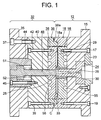
- FIG. 1 is a sectional view of a conventional disc-molding mold
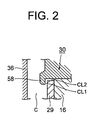
- FIG. 2 is a sectional view showing essential portions of the conventional disc-molding mold.
- reference numeral 12 denotes a stationary-side mold assembly attached to an unillustrated stationary platen by use of unillustrated bolts
- reference numeral 32 denotes a movable-side mold assembly attached to an unillustrated movable platen by use of unillustrated bolts.
- the mold assemblies 12 and 32 constitute a disc-molding mold.
- An unillustrated mold clamping mechanism is disposed behind the movable platen. Operation of the mold clamping mechanism causes the movable platen to advance and retreat, whereby the mold assembly 32 advances and retreats (moves rightward and leftward in FIG. 1) to contact and move away from the mold assembly 12. In this manner, the disc-molding mold undergoes mold closing, mold clamping, and mold opening. When mold closing is performed, a cavity C is formed between the mold assembly 12 and the mold assembly 32.
- the mold assembly 12 includes a base plate 15; a mirror-surface disc 16 attached to the base plate 15 by use of bolts 17; an annular guide ring 18 disposed radially outward of the mirror-surface disc 16 and attached to the base plate 15 by use of bolts 19; a locating ring 23 disposed in the base plate 15 in such a manner as to face the stationary platen and adapted to position the base plate 15 with respect to the stationary platen; and a sprue bush 24 disposed adjacent to the locating ring 23 and extending frontward (leftward in FIG. 1) through the base plate 15 and the mirror-surface disc 16.
- a sprue 26 is formed along the axis of the sprue bush 24 in order to allow passage of resin injected from the injection nozzle of an unillustrated injection unit.
- the front end (the left end in FIG. 1) of the sprue bush 24 faces the cavity C, and a die 28 having a recess is formed at the front end of the sprue bush 24.
- a prototype substrate which is a prototype for a disc substrate
- fine pits are formed on one side of the disc substrate, thereby forming an information side.
- a stamper 29 is attached to the front end surface (left end surface in FIG. 1) of the mirror-surface disc 16.
- the stamper 29 has fine pits formed on its front end surface and is pressed against the mirror-surface disc 16 by means of an unillustrated outer holder acting on its outer circumferential edge and an inner holder 30 acting on its inner circumferential edge.
- An unillustrated stationary-side air blow bush and the like are also disposed on the mold assembly 12.
- the mold assembly 32 includes a base plate 35; an intermediate plate 40 attached to the base plate 35 by use of bolts 37; a mirror-surface disc 36 attached to the intermediate plate 40 by use of bolts 42; an annular guide ring 38 disposed radially outward of the mirror-surface disc 36 and attached to the intermediate plate 40 by use of bolts 39; a guide member 44 disposed in the base plate 35 in such a manner as to face the movable platen and attached to the intermediate plate 40 by use of bolts 45; and a cut punch 48 disposed in opposition to the sprue bush 24 and in such a manner as to be able to advance and retreat.
- the front end (right end in FIG. 1) of the cut punch 48 has a shape corresponding to the die 28.
- An annular cavity ring 33 is disposed on the front end surface (right end surface in FIG. 1) of the mirror-surface disc 36 along the outer circumferential edge of the mirror-surface disc 36 in such a manner as to project toward the mirror-surface disc 16 by a dimension corresponding to the thickness of a disc substrate to be molded.
- the cavity ring 33 is depicted as being integral with the mirror-surface disc 36.
- the cavity ring 33 is a separate element and fixed to the mirror-surface disc 36 by use of unillustrated bolts.
- the cavity ring 33 defines a depression located radially inward thereof. When mold closing and mold clamping are performed, the depression serves as the cavity C.
- a flange 51 formed integrally with the cut punch 48 is disposed within the guide member 44 such that it can advance and retract.
- An unillustrated drive cylinder is disposed rearward (leftward in FIG. 1) of the flange 51 and, when operated, causes the flange 51 to move frontward (rightward in FIG. 1).
- a cut-punch return spring 52 is disposed between the flange 51 and the intermediate plate 40 located frontward of the flange 51. The cut-punch return spring 52 urges the flange 51 rearward.
- An ejector bush, an ejector pin, a movable-side air blow bush, and other unillustrated members are also disposed in the mold assembly 32.
- annular rabbet 18a is formed on the guide ring 18 to be located on the radially inner side thereof, and an annular rabbet 38a is formed on the guide ring 38 to be located on the radially outer side thereof.
- a temperature control medium passage 55 is formed in the mirror-surface disc 16
- a temperature control medium passage 56 is formed in the mirror-surface disc 36.
- the drive cylinder is operated so as to advance the flange 51, thereby advancing the cut punch 48.
- the front end of the cut punch 48 enters the die 28, thereby punching a hole in the prototype substrate within the cavity C.
- the punched prototype substrate is further cooled and becomes a disc substrate.
- the mold clamping mechanism is operated so as to retreat the movable platen, thereby retreating (moving leftward in FIG. 1) the mold assembly 32 for performing mold opening.
- the disc substrate is released from the stamper 29.
- the ejector pin is advanced, thereby pushing out the disc substrate from the mold assembly 32. In this manner, the disc substrate can be taken out.
- the inner holder 30 has a function of mechanically holding the inner circumferential edge of the stamper 29.
- an annular holding portion 58 is formed at the outer circumferential edge of the front end of the inner holder 30 in such a manner as to project frontward (leftward in FIG. 2) and radially outward.
- a clearance CL1 is formed between the front end surface of the mirror-surface disc 16 and the rear end surface (right end surface in FIG. 2) of the holding portion 58, and a clearance CL2 is formed between the inner circumferential surface of the stamper 29 and the outer circumferential surface of the inner holder 30. If the clearance CL1 is large, resin may enter the clearance CL1, resulting in generation of burrs on the disc substrate.
- the stamper 29 may radially go off center. This causes a failure to establish concentricity between an information region and the disc substrate, thereby impairing quality of the disc substrate.
- An object of the present invention is to solve the above-mentioned problems in the conventional disc-molding mold and to provide a mold for molding, a molding method, and a molding machine in which generation of burrs on a disc substrate can be prevented to thereby enhance quality of the disc substrate, as well as a disc substrate molded by the same.
- a mold for molding of the present invention comprises a mirror-surface disc; a stamper having a hole formed at its center, and attached to the front end surface of the mirror-surface disc; and an inner holder for holding the stamper by means of press fit into the hole.
- the inner holder is press-fitted into the hole of the stamper to thereby hold the stamper, thereby eliminating need to form a holding portion at the outer circumferential edge of the front end of the inner holder. Accordingly, an associated groove is not formed on the disc substrate. Thus, a print region on the disc substrate can be increased in area.
- the cavity is not narrowed. Accordingly, a molding material charged into the cavity exhibits good fluidity, thereby preventing formation of flow lines on the surface of the disc substrate or warpage of the disc substrate. As a result, quality of the disc substrate can be enhanced.
- FIG. 1 is a sectional view of a conventional disc-molding mold
- FIG. 2 is a sectional view showing essential portions of the conventional disc-molding mold
- FIG. 3 is a sectional view of a disc-molding mold according to a first embodiment of the present invention
- FIG. 4 is a sectional view showing essential portions of the disc-molding mold according to the first embodiment of the present invention
- FIG. 5 is an enlarged view of a press-fit deformation region in the first embodiment of the present invention
- FIG. 6 is an enlarged view showing another, first example of the press-fit deformation region in the first embodiment of the present invention
- FIG. 7 is an enlarged view showing another, second example of the press-fit deformation region in the first embodiment of the present invention
- FIG. 1 is a sectional view of a conventional disc-molding mold
- FIG. 2 is a sectional view showing essential portions of the conventional disc-molding mold
- FIG. 3 is a sectional view of a disc-mold
- FIG. 8 is an enlarged view showing another, third example of the press-fit deformation region in the first embodiment of the present invention
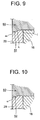
- FIG. 9 is an enlarged view showing another, fourth example of the press-fit deformation region in the first embodiment of the present invention
- FIG. 10 is an enlarged view showing another, fifth example of the press-fit deformation region in the first embodiment of the present invention
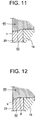
- FIG. 11 is an enlarged view showing another, sixth example of the press-fit deformation region in the first embodiment of the present invention
- FIG. 12 is an enlarged view showing another, seventh example of the press-fit deformation region in the first embodiment of the present invention
- FIG. 13 is an enlarged view showing another, eighth example of the press-fit deformation region in the first embodiment of the present invention
- FIG. 14 is an enlarged view showing a press-fit deformation region in a second embodiment of the present invention.
- a disc-molding mold will be described as a mold for molding (mold apparatus).
- FIG. 3 is a sectional view of a disc-molding mold according to a first embodiment of the present invention
- FIG. 4 is a sectional view showing essential portions of the disc-molding mold according to the first embodiment of the present invention
- FIG. 5 is an enlarged view of a press-fit deformation region in the first embodiment of the present invention.
- reference numeral 12 denotes a stationary-side mold assembly, which serves as a first mold assembly, attached to an unillustrated stationary platen by use of unillustrated bolts
- reference numeral 32 denotes a movable-side mold assembly, which serves as a second mold assembly, attached to an unillustrated movable platen by use of unillustrated bolts.
- the mold assemblies 12 and 32 constitute a disc-molding mold.
- An unillustrated mold clamping mechanism is disposed behind the movable platen. Operation of the mold clamping mechanism causes the movable platen to advance and retreat, whereby the mold assembly 32 advances and retreats (moves rightward and leftward in FIG. 3) to contact and move away from the mold assembly 12. In this manner, the disc-molding mold undergoes mold closing, mold clamping, and mold opening.
- a cavity C is formed between the mold assembly 12 and the mold assembly 32.
- the stationary platen, the movable platen, the mold clamping mechanism, and the like constitute a mold clamping apparatus.
- the disc-molding mold, the clamping apparatus, an unillustrated injection unit, and the like constitute an injection molding machine, which serves as a molding machine.
- the mold assembly 12 includes a base plate 15; a mirror-surface disc 16 attached to the base plate 15 by use of bolts 17; an annular guide ring 18 disposed radially outward of the mirror-surface disc 16 and attached to the base plate 15 by use of bolts 19; a locating ring 23 disposed in the base plate 15 in such a manner as to face the stationary platen and adapted to position the base plate 15 with respect to the stationary platen; and a sprue bush 24 disposed adjacent to the locating ring 23 and extending frontward (leftward in FIG. 3) through the base plate 15 and the mirror-surface disc 16.
- a sprue 26 is formed along the axis of the sprue bush 24 in order to allow passage of resin, which serves as a molding material, injected from the injection nozzle of the injection unit.
- the front end (the left end in FIG. 3) of the sprue bush 24 faces the cavity C, and a die 28 having a recess is formed at the front end of the sprue bush 24.
- a prototype substrate which is a prototype for a disc substrate that serves as a molded article
- fine pits are formed on one side of the disc substrate, thereby forming an information side.
- a disc-like stamper 29 which has a hole formed therein at its center and serves as an insert, is attached to the front end surface (left end surface in FIG. 3) of the mirror-surface disc 16.
- a fine pattern consisting of fine pits is formed on the front end surface of the stamper 29.
- the stamper 29 is pressed against the mirror-surface disc 16 and held by means of an unillustrated outer holder acting on its outer circumferential edge and an inner holder 60 acting on its inner circumferential edge.
- An unillustrated stationary-side air blow bush and the like are also disposed on the mold assembly 12.
- the mold assembly 32 includes a base plate 35; an intermediate plate 40 as a holding member attached to the base plate 35 by use of bolts 37; a mirror-surface disc 36 attached to the intermediate plate 40 by use of bolts 42; an annular guide ring 38 disposed radially outward of the mirror-surface disc 36 and attached to the intermediate plate 40 by use of bolts 39; a guide member 44 disposed in the base plate 35 in such a manner as to face the movable platen and attached to the intermediate plate 40 by use of bolts 45; and a cut punch 48 disposed partially in the guide member 44, in opposition to the sprue bush 24, and in such a manner as to be able to advance and retreat.
- the front end (right end in FIG. 3) of the cut punch 48 has a shape corresponding to the die 28.
- An annular cavity ring 33 is disposed on the surface of the mirror-surface disc 36 that faces the mirror-surface disc 16, along the outer circumferential edge of the mirror-surface disc 36 in such a manner as to project toward the mirror-surface disc 16 by a dimension corresponding to the thickness of a disc substrate to be molded.
- the cavity ring 33 is depicted as being integral with the mirror-surface disc 36.
- the cavity ring 33 is a separate element and fixed to the mirror-surface disc 36 by use of unillustrated bolts.
- the cavity ring 33 defines a depression located radially inward thereof. When mold closing is performed, the depression serves as the cavity C.
- a flange 51 formed integrally with the cut punch 48 is disposed within the guide member 44 such that it can advance and retract.
- An unillustrated drive cylinder is disposed rearward (leftward in FIG. 3) of the flange 51 and, when operated, causes the flange 51 to move frontward (rightward in FIG. 3).
- a cut-punch return spring 52 is disposed between the flange 51 and the intermediate plate 40 located frontward of the flange 51. The cut-punch return spring 52 urges the flange 51 rearward by a predetermined biasing force.
- An ejector bush, an ejector pin, a movable-side air blow bush, and other unillustrated members are also disposed in the mold assembly 32.
- annular rabbet 18a is formed on the guide ring 18 to be located on the radially inner side thereof, and an annular rabbet 38a is formed on the guide ring 38 to be located on the radially outer side thereof.
- a temperature control medium passage 55 is formed in the mirror-surface disc 16
- a temperature control medium passage 56 is formed in the mirror-surface disc 36.
- a temperature control medium fed from an unillustrated temperature controller flows through the temperature control medium passages 55 and 56.
- the drive cylinder is operated so as to advance the flange 51, thereby advancing the cut punch 48.
- the front end of the cut punch 48 enters the die 28, thereby punching a hole in the prototype substrate within the cavity C.
- the punched prototype substrate is further cooled and becomes a disc substrate.
- the mold clamping mechanism is operated so as to retreat the movable platen, thereby retreating (moving leftward in FIG. 3) the mold assembly 32 for performing mold opening.
- the disc substrate is released from the stamper 29.
- the ejector pin is advanced, thereby pushing out the disc substrate from the mold assembly 32. In this manner, the disc substrate can be taken out.
- the inner holder 60 has a function of mechanically holding the inner circumferential edge of the stamper 29.
- the inner holder 60 is attached to the mold assembly 12 as follows: in the course of attachment of the inner holder 60 to the mold assembly 12, the inner holder 60 is press-fitted into the hole of the stamper 29, thereby pressing the stamper 29 against the mirror-surface disc 16 and thus holding the stamper 29 in place.
- a press-fit deformation region is established at at least a portion of the outer circumferential surface of a front end portion (left end portion in FIG. 3) of the inner holder 60 and at a corresponding portion of the inner circumferential surface of the stamper 29; in the present embodiment, over the entire outer circumferential surface of the front end portion of the inner holder 60 and over the entire inner circumferential surface of the stamper 29.
- Press fit is performed in the press-fit deformation region.
- at least either the inner holder 60 or the stamper 29; in the present embodiment, the stamper 29, is subjected to stress in excess of a yield point of a material used to form the stamper 29. As a result, the stamper 29 is plastically deformed.
- the stamper 29 is formed from a first material suited for plastic deformation; for example, pure nickel, whereas the inner holder 60 is formed from a second material having higher hardness than pure nickel; for example, stainless steel.
- the press-fit deformation region may be established at each of at least two positions in the circumferential direction of the stamper 29 and the inner holder 60 and at at least one position in the axial direction of the stamper 29 and the inner holder 60.
- the outside diameter of the inner holder 60 is rendered greater than the inside diameter of the stamper 29.
- the diameter of the front end of the inner holder 60 is rendered greater than the diameter of the rear end (right end in FIG. 3) of the inner holder 60.
- reference symbol S1 denotes the inner circumferential surface of the stamper 29 before press fit is performed.
- the inner circumferential surface S1 consists of a cylindrical surface a and a curved surface b.
- the cylindrical surface a extends frontward (leftward in FIG. 4) from the rear end (right end in FIG.
- Reference symbol S2 denotes the outer circumferential surface of the inner holder 60 in the press-fit deformation region.
- the outer circumferential surface S2 consists of a plurality of surfaces axially adjacent to each other.
- the outer circumferential surface S2 assumes the same profile before and after press fit is performed, and consists of a cylindrical surface c and a conical surface d.
- the cylindrical surface c extends frontward from the rear end of the stamper 29.
- the conical surface d extends frontward from the front end of the surface c in an oblique manner such that its diameter increases gradually.
- the surface c is rendered slightly greater in diameter than the surface a.
- the diameter of the conical surface d is rendered greater than that of the curved surface b by an amount (for example, 30 ⁇ m as measured at a maximum-diameter portion) sufficient for press fit.
- the inner circumferential surface S1 is plastically deformed in the radially outward direction, thereby assuming a profile along the outer circumferential surface S2.
- the inner circumferential surface S1 and the outer circumferential surface S2 are brought into tight contact, whereby the inner holder 60 holds the stamper 29 in a sufficiently reliable manner and presses the stamper 29 against the mirror-surface disc 16.
- an unillustrated engaging mechanism is disposed within the base plate 15.
- the engaging mechanism includes an operation rod, which rotatably extends from the outside of the disc-molding mold to the vicinity of the outer circumferential surface of the inner holder 60, and an engaging portion, which is formed at an end of the operation rod and has a predetermined semicircular shape.
- the engaging portion is engaged with a predetermined portion of the rear end of the inner holder 60, thereby causing the inner holder 60 to retreat.
- the predetermined portion of the rear end of the inner holder 60 assumes, for engagement, a predetermined shape corresponding to the engaging portion of the operation rod.
- the distance of retreat of the inner holder 60 is determined such that, after press fit is performed, the front end surface of the inner holder 60 and the front end surface of the stamper 29 are present on the same plane.
- an unillustrated stopper which serves as a stop member, can be disposed at a predetermined position located rearward (rightward in FIG. 3) of the inner holder 60.
- the inner holder 60 While the stamper 29 is pressed against the mirror-surface disc 16, the inner holder 60 is inserted into the respective holes formed in the stamper 29 and the mirror-surface disc 16, and the rear end of the inner holder 60 is engaged with the engaging portion of the operation rod.
- the engaging mechanism When the engaging mechanism is operated, the inner holder 60 is retreated; accordingly, the front end of the inner holder 60 is fitted into the hole of the stamper 29, whereby the inner holder 60 is press-fitted into the hole of the stamper 29.
- the cavity C is not narrowed. Accordingly, a molding material charged into the cavity C exhibits good fluidity, thereby preventing formation of flow lines on the surface of the disc substrate or warpage of the disc substrate. As a result, quality of the disc substrate can be enhanced.
- the stamper 29 does not come off from the front end of the inner holder 60. Accordingly, the stamper 29 can be reliably held.
- a portion of the inner holder 60 where the conical surface d is formed serves as a detachment preventive portion for preventing the stamper 29 from coming off from the inner holder 60.
- the stamper 29 in the course of press fit, is plastically deformed.
- the plastic deformation arises when stress that is generated in the stamper 29 by an externally imposed force exceeds a yield point, which is the limit of elastic deformation of the stamper 29.
- the stamper In the case where the stamper is elastically deformed, the stamper fails to be firmly supported by the inner holder; as a result, the stamper may radially go off center.
- the stamper 29 is plastically deformed and firmly supported by the inner holder 60, so that the stamper 29 does not radially go off center. Accordingly, the information region and the disc substrate become concentric, thereby enhancing quality of the disc substrate.
- the positioning accuracy for the stamper 29 can be improved as follows.
- the stamper 29 is to be attached to the mirror-surface disc 16, the information region is aligned with the mirror-surface disc 16 for positioning of the stamper 29 with respect to the mirror-surface disc 16.
- the inner holder 60 is press-fitted, thereby improving the positioning accuracy for the stamper 29. Accordingly, the stamper 29 does not radially go off center.
- the inner holder 60 in press fit of the inner holder 60 into the stamper 29, only the stamper 29 is plastically deformed.
- the inner holder 60 may be plastically deformed during press fit into the stamper 29 without plastic deformation of the stamper 29.
- the inner holder 60 is configured such that its surface portion that contacts the stamper 29 and is plastically deformed is removably disposed on its base portion. Accordingly, when the stamper 29 cannot be smoothly press-fitted to the inner holder 60, smooth press fit can be achieved by replacing only the inexpensive surface portion of the inner holder 60, without need to replace the expensive stamper 29.
- both the stamper 29 and the inner holder 60 may be plastically deformed for press fit.
- FIG. 6 is an enlarged view showing another, first example of the press-fit deformation region in the first embodiment of the present invention
- FIG. 7 is an enlarged view showing another, second example of the press-fit deformation region in the first embodiment of the present invention
- FIG. 8 is an enlarged view showing another, third example of the press-fit deformation region in the first embodiment of the present invention
- FIG. 9 is an enlarged view showing another, fourth example of the press-fit deformation region in the first embodiment of the present invention
- FIG. 10 is an enlarged view showing another, fifth example of the press-fit deformation region in the first embodiment of the present invention
- FIG. 11 is an enlarged view showing another, sixth example of the press-fit deformation region in the first embodiment of the present invention
- FIG. 12 is an enlarged view showing another, seventh example of the press-fit deformation region in the first embodiment of the present invention
- FIG. 13 is an enlarged view showing another, eighth example of the press-fit deformation region in the first embodiment of the present invention.
- reference numeral 16 denotes the mirror-surface disc
- reference numeral 29 denotes the stamper
- reference numeral 60 denotes the inner holder
- reference symbol S2 denotes the outer circumferential surface of the inner holder 60 in the press-fit deformation region.
- the outer circumferential surface S2 is a conical surface e, which extends frontward (leftward in FIG. 6) from the rear end (right end in FIG. 6) of the stamper 29 in an oblique manner such that its diameter increases gradually.
- the outer circumferential surface S2 is a cylindrical surface f, which extends frontward from the rear end of the stamper 29.
- the outer circumferential surface S2 consists of a cylindrical surface g, which extends frontward from the rear end of the stamper 29; a conical surface h, which extends frontward from the front end (left end in FIG.
- the outer circumferential surface S2 consists of a cylindrical surface j, which extends frontward from the rear end of the stamper 29; a conical surface k, which extends frontward from the front end of the surface j in an oblique manner with a first angle ⁇ 1 such that its diameter increases gradually; and a conical surface m, which extends frontward from the front end of the conical surface k in an oblique manner with a second angle ⁇ 2 ( ⁇ ⁇ 1) such that its diameter increases gradually.
- the outer circumferential surface S2 is a curved surface n, which is curved frontward from the rear end of the stamper 29 such that its diameter increases gradually while its angle increases gradually.
- the outer circumferential surface S2 is a curved surface o, which is curved frontward from the rear end of the stamper 29 such that its diameter increases gradually while its angle decreases gradually.
- the outer circumferential surface S2 consists of a cylindrical surface p, which extends frontward from the rear end of the stamper 29, and a curved surface q, which is curved frontward such that its diameter increases gradually while its angle increases gradually.
- the outer circumferential surface S2 consists of a cylindrical surface r, which extends frontward from the rear end of the stamper 29, and a curved surface s, which is curved frontward such that its diameter increases gradually while its angle decreases gradually.
- the conical surface e serves as a detachment preventive portion; in the third example, the conical surface h and the surface i cooperatively serve as a detachment preventive portion; in the fourth example, the conical surfaces k and m cooperatively serve as a detachment preventive portion; in the fifth example, the curved surface n serves as a detachment preventive portion; in the sixth example, the curved surface o serves as a detachment preventive portion; in the seventh example, the curved surface q serves as a detachment preventive portion; and in the eighth example, the curved surface s serves as a detachment preventive portion.
- FIG. 14 is an enlarged view showing a press-fit deformation region in a second embodiment of the present invention.
- reference numeral 29 denotes the stamper
- reference numeral 60 denotes the inner holder.
- the inner holder 60 is formed in such a manner that its front end surface (left end surface in FIG. 14) projects from the front end surface of the stamper 29 to such a slight extent as not to narrow the cavity C (FIG. 3).
- the present invention can be applied to a mold for molding, for example, a light guide disc having a fine pattern formed thereon.
- the stamper 29 is disposed in the stationary-side mold assembly 12.
- the stamper 29 may be disposed in at least either the stationary-side mold assembly 12 or the movable-side mold assembly 32.
- the present invention can be applied to a molding machine for molding disc substrates.
Landscapes
- Engineering & Computer Science (AREA)
- Mechanical Engineering (AREA)
- Manufacturing & Machinery (AREA)
- Moulds For Moulding Plastics Or The Like (AREA)
- Manufacturing Optical Record Carriers (AREA)
- Forging (AREA)
Applications Claiming Priority (3)
| Application Number | Priority Date | Filing Date | Title |
|---|---|---|---|
| JP2002333899 | 2002-11-18 | ||
| JP2002333899 | 2002-11-18 | ||
| PCT/JP2003/014572 WO2004045822A1 (ja) | 2002-11-18 | 2003-11-17 | 成形用金型、成形方法、ディスク基板及び成形機 |
Publications (2)
| Publication Number | Publication Date |
|---|---|
| EP1568458A1 true EP1568458A1 (de) | 2005-08-31 |
| EP1568458A4 EP1568458A4 (de) | 2009-05-27 |
Family
ID=32321712
Family Applications (1)
| Application Number | Title | Priority Date | Filing Date |
|---|---|---|---|
| EP03772811A Withdrawn EP1568458A4 (de) | 2002-11-18 | 2003-11-17 | Spritzwerkzeug, spritzverfahren, scheibensubstrat und formmaschine |
Country Status (8)
| Country | Link |
|---|---|
| US (1) | US20060051552A1 (de) |
| EP (1) | EP1568458A4 (de) |
| JP (1) | JP4290654B2 (de) |
| KR (1) | KR100710727B1 (de) |
| CN (1) | CN100425419C (de) |
| AU (1) | AU2003280817A1 (de) |
| TW (1) | TWI241948B (de) |
| WO (1) | WO2004045822A1 (de) |
Families Citing this family (8)
| Publication number | Priority date | Publication date | Assignee | Title |
|---|---|---|---|---|
| JP4262150B2 (ja) * | 2004-06-30 | 2009-05-13 | 富士フイルム株式会社 | 導光体の射出成形型および製造装置 |
| JP4593572B2 (ja) * | 2004-11-18 | 2010-12-08 | パナソニック株式会社 | 射出成形装置、射出成形方法及び射出成形金型 |
| JP4345064B2 (ja) * | 2005-03-25 | 2009-10-14 | セイコーエプソン株式会社 | 光電変換素子の製造方法、および電子機器 |
| JP4647568B2 (ja) * | 2006-09-12 | 2011-03-09 | 東洋機械金属株式会社 | 射出成形機 |
| JP4491024B2 (ja) * | 2008-05-12 | 2010-06-30 | 株式会社東芝 | 金型装置 |
| JP5600401B2 (ja) * | 2009-06-15 | 2014-10-01 | 株式会社精工技研 | ディスク成形用金型、インナホルダ及びディスク成形用金型の製造方法 |
| JP6444630B2 (ja) | 2014-06-24 | 2018-12-26 | Nok株式会社 | インサート成形用金型構造 |
| TWI741859B (zh) * | 2020-10-28 | 2021-10-01 | 張再順 | 用於成型機的快速換模裝置(三) |
Family Cites Families (25)
| Publication number | Priority date | Publication date | Assignee | Title |
|---|---|---|---|---|
| JPS63182117A (ja) * | 1987-01-26 | 1988-07-27 | Daicel Chem Ind Ltd | デイスク成形用金型 |
| JP3192174B2 (ja) * | 1991-08-28 | 2001-07-23 | 株式会社日立製作所 | 光ディスク基板の成形金型およびその製造方法 |
| JP2944359B2 (ja) * | 1993-03-23 | 1999-09-06 | 株式会社精工技研 | 基盤射出成形金型 |
| JP3099168B2 (ja) * | 1994-05-25 | 2000-10-16 | 株式会社名機製作所 | ディスク基板成形用金型 |
| DE9412214U1 (de) * | 1994-07-28 | 1994-09-22 | Galic/Maus Ventures, Columbia Heights, Minn. | Matrizenrückhaltesystem in Spritzgußformen für optische Platten |
| JP3264419B2 (ja) * | 1995-12-26 | 2002-03-11 | 日本ビクター株式会社 | 記録ディスク及び成形用金型装置 |
| JP3002418B2 (ja) * | 1996-03-22 | 2000-01-24 | 株式会社精工技研 | 光ディスク成形用金型装置 |
| CN1195313A (zh) * | 1996-05-10 | 1998-10-07 | 索尼株式会社 | 盘基板成形用金属模具及其制造方法以及盘基板 |
| JP3893649B2 (ja) * | 1996-10-30 | 2007-03-14 | 松下電器産業株式会社 | 記録媒体用ディスク成形装置 |
| NL1005502C2 (nl) * | 1997-03-12 | 1998-09-15 | Ict Axxicon Bv | Matrijs voor het vervaardigen van schijfvormige voorwerpen. |
| EP0872331A1 (de) * | 1997-04-16 | 1998-10-21 | Matsushita Electric Industrial Co., Ltd. | Prägeplatten-Schutzschicht für eine Vorrichtung zum Spritzgiessen eines optischen Informationsträgers, Vorrichtung zum Spritzgiessen eines optischen Informationsträgers, Verfahren zum Spritzgiesen eines optischen Informationsträgers mit dem Prägeplatten-Schutzschicht |
| JP3859301B2 (ja) * | 1997-04-28 | 2006-12-20 | 松下電器産業株式会社 | 光ディスク成形装置 |
| JP3490265B2 (ja) * | 1997-08-29 | 2004-01-26 | 株式会社名機製作所 | 薄物ディスク基板の成形方法およびその成形用金型 |
| JPH1170529A (ja) * | 1997-08-29 | 1999-03-16 | Seiko Giken:Kk | ディスク成形用金型 |
| NL1008105C2 (nl) * | 1998-01-23 | 1999-07-26 | Axxicon Moulds Eindhoven Bv | Spuitgietmatrijs. |
| JP3646516B2 (ja) * | 1998-04-08 | 2005-05-11 | セイコーエプソン株式会社 | 剥離方法 |
| US6139307A (en) * | 1998-07-23 | 2000-10-31 | Imation Corp. | Assembly for molding optical data storage disks formatted on both sides |
| CN1222399C (zh) * | 1998-09-11 | 2005-10-12 | 株式会社理光 | 塑料成形品及其成形方法 |
| CN1140396C (zh) * | 2000-08-04 | 2004-03-03 | 株式会社精工技研 | 圆盘模制模具 |
| JP2002100078A (ja) * | 2000-09-26 | 2002-04-05 | Sony Corp | ディスク基板用のスタンパ及び成形金型装置 |
| JP2002166448A (ja) * | 2000-12-01 | 2002-06-11 | Sony Corp | 成形用金型装置および成形方法 |
| JP2002240101A (ja) * | 2000-12-15 | 2002-08-28 | Sony Corp | ディスク基板及びそれを射出成形する金型装置とディスク基板取出し用ロボット |
| JP3625430B2 (ja) * | 2001-03-15 | 2005-03-02 | 松下電器産業株式会社 | スタンパ交換方法と光ディスク成形金型 |
| JP4105513B2 (ja) * | 2002-09-25 | 2008-06-25 | Tdk株式会社 | 金型装置 |
| JP3977772B2 (ja) * | 2003-05-14 | 2007-09-19 | 株式会社名機製作所 | ディスク基板の成形用金型 |
-
2003
- 2003-11-17 AU AU2003280817A patent/AU2003280817A1/en not_active Abandoned
- 2003-11-17 WO PCT/JP2003/014572 patent/WO2004045822A1/ja not_active Ceased
- 2003-11-17 CN CNB200380103592XA patent/CN100425419C/zh not_active Expired - Fee Related
- 2003-11-17 US US10/534,488 patent/US20060051552A1/en not_active Abandoned
- 2003-11-17 TW TW092132099A patent/TWI241948B/zh not_active IP Right Cessation
- 2003-11-17 JP JP2004553176A patent/JP4290654B2/ja not_active Expired - Lifetime
- 2003-11-17 EP EP03772811A patent/EP1568458A4/de not_active Withdrawn
- 2003-11-17 KR KR1020057008883A patent/KR100710727B1/ko not_active Expired - Fee Related
Also Published As
| Publication number | Publication date |
|---|---|
| TWI241948B (en) | 2005-10-21 |
| JPWO2004045822A1 (ja) | 2006-03-16 |
| KR100710727B1 (ko) | 2007-04-23 |
| WO2004045822A1 (ja) | 2004-06-03 |
| CN100425419C (zh) | 2008-10-15 |
| JP4290654B2 (ja) | 2009-07-08 |
| TW200418626A (en) | 2004-10-01 |
| US20060051552A1 (en) | 2006-03-09 |
| AU2003280817A8 (en) | 2004-06-15 |
| CN1713971A (zh) | 2005-12-28 |
| EP1568458A4 (de) | 2009-05-27 |
| AU2003280817A1 (en) | 2004-06-15 |
| KR20050085029A (ko) | 2005-08-29 |
Similar Documents
| Publication | Publication Date | Title |
|---|---|---|
| EP0355589B1 (de) | Giessform zum Giessen der Grundlage einer optischen Platte | |
| US6558152B2 (en) | Disc-molding mold | |
| EP1568458A1 (de) | Spritzwerkzeug, spritzverfahren, scheibensubstrat und formmaschine | |
| EP0722818B1 (de) | Giessform für eine Platte | |
| EP0899075A1 (de) | Form zum Giessen einer Platte | |
| US20090232930A1 (en) | Disk Molding Mold, Mirror Surface Disk, and Method of Manufacturing Mirror Surface Disk | |
| US20070275115A1 (en) | Mold For Molding Disk, Mirror-Surface Disk, And Molded Product | |
| US20070176311A1 (en) | Mold for molding disk, adjustment member, and method of molding disk substrate | |
| JP2918144B2 (ja) | 射出成形用金型 | |
| US20090074904A1 (en) | Mold for forming disc, method for manufacture same, and mold parts | |
| EP2085206A1 (de) | Plattenformwerkzeug und spiegelflächenplatte | |
| JP5600401B2 (ja) | ディスク成形用金型、インナホルダ及びディスク成形用金型の製造方法 | |
| EP2095928A1 (de) | Scheibenformgesenk, scheibensubstrat und verfahren zum formen des scheibensubstrats | |
| KR100220156B1 (ko) | 디스크 성형용 금형 | |
| JP3631539B2 (ja) | ディスク成形金型 | |
| JPH08300419A (ja) | 射出成形用金型 | |
| EP1955834A1 (de) | Formvorrichtung und spiegelplatte | |
| JP2008094078A (ja) | 微細加工方法および微細加工基板 | |
| JP2006107555A (ja) | 光ディスク成形用金型装置 | |
| JPH1015949A (ja) | ディスク成形用金型 | |
| JP2006068974A (ja) | 光ディスク成形用金型装置 |
Legal Events
| Date | Code | Title | Description |
|---|---|---|---|
| PUAI | Public reference made under article 153(3) epc to a published international application that has entered the european phase |
Free format text: ORIGINAL CODE: 0009012 |
|
| 17P | Request for examination filed |
Effective date: 20050517 |
|
| AK | Designated contracting states |
Kind code of ref document: A1 Designated state(s): AT BE BG CH CY CZ DE DK EE ES FI FR GB GR HU IE IT LI LU MC NL PT RO SE SI SK TR |
|
| AX | Request for extension of the european patent |
Extension state: AL LT LV MK |
|
| DAX | Request for extension of the european patent (deleted) | ||
| A4 | Supplementary search report drawn up and despatched |
Effective date: 20090427 |
|
| RIC1 | Information provided on ipc code assigned before grant |
Ipc: B29C 45/26 20060101ALI20090421BHEP Ipc: B29C 33/30 20060101AFI20040604BHEP |
|
| 17Q | First examination report despatched |
Effective date: 20090708 |
|
| STAA | Information on the status of an ep patent application or granted ep patent |
Free format text: STATUS: THE APPLICATION IS DEEMED TO BE WITHDRAWN |
|
| 18D | Application deemed to be withdrawn |
Effective date: 20091119 |