EP1567876B1 - Verfahren zum ersetzen einer sekundärbatterie - Google Patents
Verfahren zum ersetzen einer sekundärbatterie Download PDFInfo
- Publication number
- EP1567876B1 EP1567876B1 EP03775635A EP03775635A EP1567876B1 EP 1567876 B1 EP1567876 B1 EP 1567876B1 EP 03775635 A EP03775635 A EP 03775635A EP 03775635 A EP03775635 A EP 03775635A EP 1567876 B1 EP1567876 B1 EP 1567876B1
- Authority
- EP
- European Patent Office
- Prior art keywords
- battery
- fresh
- secondary batteries
- charged
- replaced
- Prior art date
- Legal status (The legal status is an assumption and is not a legal conclusion. Google has not performed a legal analysis and makes no representation as to the accuracy of the status listed.)
- Expired - Lifetime
Links
Images


Classifications
-
- H—ELECTRICITY
- H01—ELECTRIC ELEMENTS
- H01M—PROCESSES OR MEANS, e.g. BATTERIES, FOR THE DIRECT CONVERSION OF CHEMICAL ENERGY INTO ELECTRICAL ENERGY
- H01M10/00—Secondary cells; Manufacture thereof
- H01M10/42—Methods or arrangements for servicing or maintenance of secondary cells or secondary half-cells
- H01M10/44—Methods for charging or discharging
-
- H—ELECTRICITY
- H02—GENERATION; CONVERSION OR DISTRIBUTION OF ELECTRIC POWER
- H02J—CIRCUIT ARRANGEMENTS OR SYSTEMS FOR SUPPLYING OR DISTRIBUTING ELECTRIC POWER; SYSTEMS FOR STORING ELECTRIC ENERGY
- H02J7/00—Circuit arrangements for charging or depolarising batteries or for supplying loads from batteries
-
- G—PHYSICS
- G01—MEASURING; TESTING
- G01R—MEASURING ELECTRIC VARIABLES; MEASURING MAGNETIC VARIABLES
- G01R31/00—Arrangements for testing electric properties; Arrangements for locating electric faults; Arrangements for electrical testing characterised by what is being tested not provided for elsewhere
- G01R31/36—Arrangements for testing, measuring or monitoring the electrical condition of accumulators or electric batteries, e.g. capacity or state of charge [SoC]
- G01R31/392—Determining battery ageing or deterioration, e.g. state of health
-
- H—ELECTRICITY
- H01—ELECTRIC ELEMENTS
- H01M—PROCESSES OR MEANS, e.g. BATTERIES, FOR THE DIRECT CONVERSION OF CHEMICAL ENERGY INTO ELECTRICAL ENERGY
- H01M10/00—Secondary cells; Manufacture thereof
- H01M10/42—Methods or arrangements for servicing or maintenance of secondary cells or secondary half-cells
- H01M10/4207—Methods or arrangements for servicing or maintenance of secondary cells or secondary half-cells for several batteries or cells simultaneously or sequentially
-
- H02J7/575—
-
- H—ELECTRICITY
- H01—ELECTRIC ELEMENTS
- H01M—PROCESSES OR MEANS, e.g. BATTERIES, FOR THE DIRECT CONVERSION OF CHEMICAL ENERGY INTO ELECTRICAL ENERGY
- H01M10/00—Secondary cells; Manufacture thereof
- H01M10/34—Gastight accumulators
- H01M10/345—Gastight metal hydride accumulators
-
- Y—GENERAL TAGGING OF NEW TECHNOLOGICAL DEVELOPMENTS; GENERAL TAGGING OF CROSS-SECTIONAL TECHNOLOGIES SPANNING OVER SEVERAL SECTIONS OF THE IPC; TECHNICAL SUBJECTS COVERED BY FORMER USPC CROSS-REFERENCE ART COLLECTIONS [XRACs] AND DIGESTS
- Y02—TECHNOLOGIES OR APPLICATIONS FOR MITIGATION OR ADAPTATION AGAINST CLIMATE CHANGE
- Y02E—REDUCTION OF GREENHOUSE GAS [GHG] EMISSIONS, RELATED TO ENERGY GENERATION, TRANSMISSION OR DISTRIBUTION
- Y02E60/00—Enabling technologies; Technologies with a potential or indirect contribution to GHG emissions mitigation
- Y02E60/10—Energy storage using batteries
-
- Y—GENERAL TAGGING OF NEW TECHNOLOGICAL DEVELOPMENTS; GENERAL TAGGING OF CROSS-SECTIONAL TECHNOLOGIES SPANNING OVER SEVERAL SECTIONS OF THE IPC; TECHNICAL SUBJECTS COVERED BY FORMER USPC CROSS-REFERENCE ART COLLECTIONS [XRACs] AND DIGESTS
- Y02—TECHNOLOGIES OR APPLICATIONS FOR MITIGATION OR ADAPTATION AGAINST CLIMATE CHANGE
- Y02T—CLIMATE CHANGE MITIGATION TECHNOLOGIES RELATED TO TRANSPORTATION
- Y02T10/00—Road transport of goods or passengers
- Y02T10/60—Other road transportation technologies with climate change mitigation effect
- Y02T10/70—Energy storage systems for electromobility, e.g. batteries
Definitions
- the invention relates to a secondary battery replacement method for replacing one or more secondary batteries in a battery assembly formed by electrically connecting a plurality of secondary batteries in series or parallel if the one or more secondary batteries have degradation (including reduction in the fully charged capacity, acquisition of memory effect, etc.), or if the one or more batteries reach the end of service life or have a failure. More particularly, the invention relates to a method for replacing secondary batteries installed in pure electric vehicles (PEVs) or hybrid engine vehicles (HEVs).
- PEVs pure electric vehicles
- HEVs hybrid engine vehicles
- Examples of the secondary battery include lead-acid batteries, nickel-cadmium (Ni-Cd) batteries, nickel-metal hydride (Ni-MH) batteries, lithium ion batteries, etc.
- Each secondary battery has a characteristic that, when exhausted, the battery can be charged by connecting the battery to an external electric power supply and supplying a predetermined current to the battery. Due to this characteristic, secondary batteries have been used in various appliances. For example, secondary batteries are installed in conventional motor vehicles in order to supply power to ignition plugs of engines.
- Ni-MH batteries are adopted as a main electric power source for driving the electric motor, due to the high energy density (i.e., compact storage of energy) and the high output density of the Ni-MH batteries.
- battery assemblies are each formed by combining a plurality of unit cells in series or parallel, and are used as a battery pack, in order to supply sufficient power to the electric motor.
- the replacement method disclosed in Japanese Patent Application Laid-Open Publication No. 2002-15781 is a method for replacing one or more of the secondary batteries that are electrically connected in series or parallel so as to form a battery assembly with replacement batteries if the one or more secondary batteries are found faulty.
- the replacement method includes the steps of: detecting the voltage of each one of predetermined voltage detection blocks of the secondary batteries forming the battery assembly; determining whether a voltage detection block has any faulty battery on a block-by-block basis; and replacing the secondary batteries of the voltage detection block that includes the battery that is found faulty by the determining step with replacement batteries.
- the following problems may arise: (1) due to varied remaining capacities of the secondary batteries of a battery assembly, the discharge operation of the battery assembly is restricted by a battery that has a small remaining capacity, and the charge operation is restricted by a battery that has a large remaining capacity, so that the capacity of the entire battery assembly cannot be fully utilized; (2) due to varied self-discharge characteristics of the secondary batteries of a battery assembly, the discharge operation of the battery assembly secondary batteries of a battery assembly, the discharge operation of the battery assembly is restricted by a battery of a great self-discharge characteristic, and the charge is restricted by a battery of a small discharge characteristic, so that varied remaining capacities will be caused; and (3) due to varied internal resistances of secondary batteries of a battery assembly, for example, in a case where replacement batteries having great internal resistance are incorporated into the battery assembly, determination of a capacity may produce an error with respect to the actual capacity depending on the method of determination adopted, so that the battery assembly
- a replacement battery module that is higher in capacity rank than any one of the battery modules of the assembly that are not to be replaced, that is, a replacement battery module that will be in the top capacity rank when incorporated into the battery assembly, is selected from battery modules transported and stored at low temperature.
- the not-replaced secondary batteries have a region of low charging efficiency in a region where the quantity of charged electricity is high (high SOC region) as indicated in FIG 7A, due to aging degradation or memory effect acquired during use.
- the replacement battery module is a fresh module having a greater charging capacity than the other battery modules, and provides a normal charging efficiency in a region equivalent to the region of low charging efficiency of the not-replaced battery modules. If a battery assembly formed by a combination of secondary batteries having different charging efficiencies as described above is subjected to repeated charge-discharge cycles without any special process, such as an equalizing process or the like, the different charging efficiencies of the batteries result in varied states of charge (SOC).
- SOC states of charge
- Document US-A-6072300 discloses a battery state diagnostic apparatus for a battery set, which serves to detect whether there is an abnormal battery cell present in a battery set. Moreover, this document describes a battery module replacing method. According to this method, a new battery module is to be charged on the average charge of the battery set before exchanging the batteries.
- Document EP-A-1 150 132 discloses a method of replacing a secondary battery, and describes the use of a nickel-metal hydride battery.
- An object of the invention is to provide a secondary battery replacement method that allows maximum performance of a battery assembly as a whole after replacement of a battery module of the battery assembly, while avoiding a false detection of battery abnormality without the need to perform a special process, such as an equalizing process or the like, after the replacement.
- the fresh secondary battery when a secondary battery in a battery assembly made up of a plurality of secondary batteries is to be replaced with a fresh secondary battery, the fresh secondary battery is charged so that the quantity of charged electricity of the one or more fresh secondary batteries is less than the respective quantity of charged electricity of the secondary batteries present in the battery assembly which are not the one or more to-be-replaced secondary batteries. For example, if one of the fifteen secondary batteries of a battery assembly installed in an HEV is to be replaced upon a diagnosis of battery abnormality, the fresh secondary battery is charged so that the quantity of charged electricity of the fresh secondary battery is 5 to 20% less than a quantity of charged electricity of the fourteen secondary batteries other than the to-be-replaced battery.
- the fresh battery as the time of use increases, gradually degrades and acquires memory effect, so that the operating region thereof shifts to a low SOC region.
- the fresh battery comes to have substantially the same capacity as the other batteries merely through charge-discharge cycles. Therefore, according to the invention, it is possible to provide a secondary battery replacement method that allows maximum performance of a battery assembly as a whole after replacement of a secondary battery of the battery assembly with a fresh secondary battery, while avoiding a false detection of battery abnormality or avoiding overcharge of the fresh battery, without the need to perform a special process, such as an equalizing process or the like, after the replacement.
- the to-be-replaced secondary battery may be a secondary battery having a reduced full-charged capacity or a secondary battery possessing a memory effect.
- a secondary battery replacement method that allows maximum performance of a battery assembly as a whole by replacing a secondary battery having a reduced full-charged capacity or a secondary battery possessing a memory effect.
- the replacing step may include the step of incorporating the charged fresh secondary battery into a portion of the battery assembly where temperature is high. This incorporating step will accelerate the equalization of performances of the secondary batteries of the battery assembly, since the fresh secondary battery degrades faster due to the effect of temperature..
- the charging step may include the step of charging the fresh secondary battery so that the quantity of charged electricity of the fresh secondary battery is 5 to 20% less than the respective quantity of charged electricity of the secondary batteries present in the battery assembly which are not the one or more to-be-replaced secondary battery.
- This charging step avoids a difference in the quantity of charged electricity which is greater than 20%, and therefore avoids detection of battery abnormality by a battery ECU.
- the charging step also avoids a difference in the quantity of charged electricity which is less than 5%, and therefore avoids a failure in the equalization.
- the secondary battery may be a nickel-metal hydride battery.
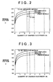
- FIG 3 is a diagram (second diagram) indicating a relationship between the quantity of charged electricity and the module voltage.
- FIG. 4 is diagram (third diagram) indicating a relationship between the quantity of charged electricity and the module voltage.
- FIG. 5 provides a brief description of chemical reactions that occur in a battery.
- FIGS. 6A and 6B indicate the states of modules at the time of incorporation of a fresh module and after the incorporation.
- FIGS. 7A and 7B illustrate a problem of a conventional replacement method.
- the “secondary battery” in the invention refers to a mono-block type battery module formed as a battery assembly by a single unit cell or by internally connecting a plurality of unit cells.
- the “secondary battery” in the invention is not limited to secondary batteries in a battery assembly which are electrically connected in series or parallel, but also includes secondary batteries in a battery assembly system which are combined in series or parallel.
- a Ni-MH secondary battery that is, a type of alkali secondary battery
- a battery module in which a battery jar assembly is formed by integrally connecting six rectangular parallelepiped-shaped battery jars at their short-side surfaces, and in which an upper surface opening of each battery jar is closed integrally with a lid, and the unit cells adjacent to each other at upper end portions of the adjacent short-side surfaces of the battery jars are internally connected .
- the rated voltage of each cell is 1.2 V
- the rated voltage of a block is 14.4 connecting about 15 blocks in series (the rated voltage of the battery assembly is 216 V).
- step (hereinafter, simply referred to as "S") 100 a battery module to be replaced is selected.
- the selection of a battery module to be replaced is based on the OCV (open circuit voltage), the SOC, the state of discharge, the value of internal resistance, the full-charged capacity, the state of self-discharge, etc. that are detected on each battery module. For example, a battery module having an increased value of internal resistance or a battery module having a reduced full-charged capacity is selected as a to-be-replaced battery module.
- a pre-replacement process is performed on a replacement battery module, that is, a fresh battery module, before the fresh module is incorporated into the battery assembly.
- the replacement battery module is charged so that the quantity of charged electricity of the replacement battery module becomes 5 to 20% less than the detected quantity of charged electricity regarding the battery modules that are not replaced, as indicated in FIG 2. For example, if the quantity of charged electricity of a not-replaced battery module is 3.0 Ah, the replacement battery module is charged up to 2.4 to 2.85 Ah as indicated in FIG. 2. In contrast, in a conventional technology, if the quantity of charged electricity of a not-replaced battery module is 3.0 Ah, the replacement battery module is also charged up to 3.0 Ah as indicated in FIG 3.
- the to-be-replaced battery module is replaced with the replacement battery module.
- the replacement battery module may be incorporated at a location in the battery assembly where temperature becomes highest.
- the location in the battery assembly where temperature becomes highest is, for example, the location of a battery module disposed in the middle of a plurality of battery modules in the assembly, or the location of a battery module that is unlikely to receive cooling air flow.
- the rebuilt battery assembly is subjected to a charge-discharge process corresponding to the not-replaced battery module whose performances have been substantially equalized. During this process, a battery ECU controls the charge-discharge state. As indicated in FIG 4, a Ni-MH secondary battery has a region of low charging efficiency in a high SOC region. This will be explained below.
- This heat generation occurs in a region of SOC exceeding 80%. That is, a portion of the electric energy supplied to charge the secondary battery is not stored but is converted into heat energy. Therefore, the charging efficiency decreases. Therefore, normally, the charge-discharge region is set so as to avoid the region of SOC exceeding 80%.
- This setting for avoiding the region of low charging efficiency is determined corresponding to a second battery (a not-replaced battery module) that has a low full-charged capacity.
- a second battery a not-replaced battery module
- the fresh secondary battery is not degraded, and the fresh battery module is free of memory effect.
- the operating region of the fresh battery module gradually shifts to a high SOC region. Since due to the pre-replacement process in S110, the fresh battery module has a smaller quantity of charged electricity than the not-replaced battery modules at the beginning of the charge-discharge process, the aforementioned shift to the high SOC region relatively delays. Therefore, the charging efficiency does not become low, and maximum performance of the battery assembly as a whole can be delivered.
- the fresh battery module gradually degrades and acquires memory effect, so that the operating region thereof shifts to a low SOC region. That is, after repeated cycles of the charge-discharge process, the fresh battery module comes to have the same capacity as the other battery modules.
- the state of charge of a replacement (fresh) battery module in a battery assembly is 5 to 20% lower than the state of charge of the not-replaced battery modules at the time of the rebuilding of the battery assembly.
- a fresh battery module is incorporated as a battery module disposed at or near a central location in the battery where temperature is high.
- the operating region of the fresh battery module shifts from the high SOC side during an initial period to the low SOC side due to the aging degradation and the memory effect, so that the capacities of the battery modules become appropriately equalized as indicated in FIG 6B.
- the replacement battery module shifts more quickly to the high SOC region where the charging efficiency is low, so that appropriate equalization of the battery modules cannot be achieved.
- a replacement battery module to be incorporated is set at an quantity of charged electricity that is 5 to 20% lower than that of the not-replaced battery modules
- the reference in this process may instead be SOC.
Landscapes
- Engineering & Computer Science (AREA)
- Manufacturing & Machinery (AREA)
- Chemical & Material Sciences (AREA)
- Chemical Kinetics & Catalysis (AREA)
- Electrochemistry (AREA)
- General Chemical & Material Sciences (AREA)
- Physics & Mathematics (AREA)
- General Physics & Mathematics (AREA)
- Secondary Cells (AREA)
- Power Engineering (AREA)
- Charge And Discharge Circuits For Batteries Or The Like (AREA)
Claims (5)
- Sekundärbatterie-Ersetzverfahren zum Ersetzen von einer oder mehreren zu ersetzenden Sekundärbatterien mit einer oder mehreren frischen Sekundärbatterien in einer Batterieanordnung, die durch elektrisches Verbinden einer Vielzahl von Sekundärbatterien parallel oder in Reihe gebildet ist, gekennzeichnet durch die Schritte:Laden der einen oder mehreren frischen Sekundärbatterien derart, dass die Ladungsgröße der einen oder mehreren frischen Sekundärbatterie geringer als die jeweilige Ladungsgröße der in der Batterieanordnung vorhandenen Sekundärbatterien ist, bei denen es sich nicht um die eine oder mehreren zu ersetzenden Sekundärbatterien handelt, undErsetzen der einen oder mehreren zu ersetzenden Sekundärbatterien mit der einen oder den mehreren frischen Sekundärbatterien, die in dem Ladeschritt geladen worden sind.
- Verfahren nach Anspruch 1, wobei die zu ersetzende Sekundärbatterie eine Sekundärbatterie mit einer verringerten vollständig geladenen Kapazität oder eine Sekundärbatterie ist, die einen Memory-Effekt besitzt.
- Verfahren nach Anspruch 1 oder 2, wobei der Ersetzschritt den Schritt Einsetzen der frischen Sekundärbatterie in einen Abschnitt der Batterieanordnung aufweist, in dem die Temperatur hoch ist.
- Verfahren nach einem der Ansprüche 1 bis 3, wobei der Ladeschritt den Schritt aufweist: Laden der einen oder mehreren frischen Sekundärbatterien derart, dass die Ladungsgröße der einen oder mehreren frischen Sekundärbatterien 5 bis 20 % niedriger als die jeweilige Ladungsgröße der in der Batterieanordnung vorhandenen Sekundärbatterien ist, bei denen es sich nicht um die eine oder mehreren zu ersetzenden Sekundärbatterien handelt.
- Verfahren nach einem der Schritte 1 bis 4, wobei die Sekundärbatterie eine Nickel-Metall-Hydrid-Batterie ist.
Applications Claiming Priority (3)
| Application Number | Priority Date | Filing Date | Title |
|---|---|---|---|
| JP2002350173A JP4134704B2 (ja) | 2002-12-02 | 2002-12-02 | 二次電池の交換方法 |
| JP2002350173 | 2002-12-02 | ||
| PCT/IB2003/005535 WO2004051296A1 (en) | 2002-12-02 | 2003-12-01 | Secondary battery replacement method |
Publications (2)
| Publication Number | Publication Date |
|---|---|
| EP1567876A1 EP1567876A1 (de) | 2005-08-31 |
| EP1567876B1 true EP1567876B1 (de) | 2007-02-28 |
Family
ID=32463070
Family Applications (1)
| Application Number | Title | Priority Date | Filing Date |
|---|---|---|---|
| EP03775635A Expired - Lifetime EP1567876B1 (de) | 2002-12-02 | 2003-12-01 | Verfahren zum ersetzen einer sekundärbatterie |
Country Status (7)
| Country | Link |
|---|---|
| US (1) | US7626364B2 (de) |
| EP (1) | EP1567876B1 (de) |
| JP (1) | JP4134704B2 (de) |
| KR (1) | KR100749838B1 (de) |
| CN (1) | CN100395559C (de) |
| DE (1) | DE60312207T2 (de) |
| WO (1) | WO2004051296A1 (de) |
Families Citing this family (81)
| Publication number | Priority date | Publication date | Assignee | Title |
|---|---|---|---|---|
| US8198900B2 (en) | 1996-07-29 | 2012-06-12 | Midtronics, Inc. | Automotive battery charging system tester |
| US6566883B1 (en) * | 1999-11-01 | 2003-05-20 | Midtronics, Inc. | Electronic battery tester |
| US8872517B2 (en) | 1996-07-29 | 2014-10-28 | Midtronics, Inc. | Electronic battery tester with battery age input |
| US6850037B2 (en) | 1997-11-03 | 2005-02-01 | Midtronics, Inc. | In-vehicle battery monitor |
| US7705602B2 (en) * | 1997-11-03 | 2010-04-27 | Midtronics, Inc. | Automotive vehicle electrical system diagnostic device |
| US8958998B2 (en) * | 1997-11-03 | 2015-02-17 | Midtronics, Inc. | Electronic battery tester with network communication |
| US7446536B2 (en) * | 2000-03-27 | 2008-11-04 | Midtronics, Inc. | Scan tool for electronic battery tester |
| US8513949B2 (en) * | 2000-03-27 | 2013-08-20 | Midtronics, Inc. | Electronic battery tester or charger with databus connection |
| US7398176B2 (en) | 2000-03-27 | 2008-07-08 | Midtronics, Inc. | Battery testers with secondary functionality |
| US9255955B2 (en) | 2003-09-05 | 2016-02-09 | Midtronics, Inc. | Method and apparatus for measuring a parameter of a vehicle electrical system |
| US8164343B2 (en) | 2003-09-05 | 2012-04-24 | Midtronics, Inc. | Method and apparatus for measuring a parameter of a vehicle electrical system |
| US7154276B2 (en) * | 2003-09-05 | 2006-12-26 | Midtronics, Inc. | Method and apparatus for measuring a parameter of a vehicle electrical system |
| US9018958B2 (en) | 2003-09-05 | 2015-04-28 | Midtronics, Inc. | Method and apparatus for measuring a parameter of a vehicle electrical system |
| US8442877B2 (en) * | 2004-08-20 | 2013-05-14 | Midtronics, Inc. | Simplification of inventory management |
| US9496720B2 (en) | 2004-08-20 | 2016-11-15 | Midtronics, Inc. | System for automatically gathering battery information |
| US8344685B2 (en) | 2004-08-20 | 2013-01-01 | Midtronics, Inc. | System for automatically gathering battery information |
| US8436619B2 (en) * | 2004-08-20 | 2013-05-07 | Midtronics, Inc. | Integrated tag reader and environment sensor |
| JP5550805B2 (ja) * | 2006-07-18 | 2014-07-16 | エルジー・ケム・リミテッド | 安定した電極リード−電極タブ結合部を有する電極組立体及びこれを備えた電気化学セル |
| JP5027005B2 (ja) * | 2007-05-11 | 2012-09-19 | プライムアースEvエナジー株式会社 | 組電池の調整方法、及びコントローラ付き組電池の調整方法 |
| US8143854B2 (en) | 2007-05-11 | 2012-03-27 | Panasonic Ev Energy Co., Ltd. | Adjusting method of battery pack and adjusting method of battery pack with controller |
| JP5319081B2 (ja) | 2007-05-22 | 2013-10-16 | プライムアースEvエナジー株式会社 | コントローラ付き組電池の製造方法 |
| JP5096806B2 (ja) | 2007-06-20 | 2012-12-12 | プライムアースEvエナジー株式会社 | 組電池の製造方法 |
| JP5011007B2 (ja) * | 2007-07-04 | 2012-08-29 | プライムアースEvエナジー株式会社 | 組電池及びその製造方法 |
| JP5096817B2 (ja) | 2007-07-10 | 2012-12-12 | プライムアースEvエナジー株式会社 | 再構成組電池の製造方法 |
| WO2009011875A2 (en) | 2007-07-17 | 2009-01-22 | Midtronics, Inc. | Battery tester for electric vehicle |
| US9274157B2 (en) * | 2007-07-17 | 2016-03-01 | Midtronics, Inc. | Battery tester for electric vehicle |
| JP5241188B2 (ja) * | 2007-09-28 | 2013-07-17 | 三洋電機株式会社 | アルカリ蓄電池システム |
| JP5196938B2 (ja) * | 2007-09-28 | 2013-05-15 | 三洋電機株式会社 | アルカリ蓄電池システム |
| CN101515023A (zh) * | 2007-12-06 | 2009-08-26 | 密特电子公司 | 蓄电池和电池测试器 |
| JP5276357B2 (ja) * | 2008-05-19 | 2013-08-28 | プライムアースEvエナジー株式会社 | ニッケル−水素二次電池の交換方法 |
| JP5338337B2 (ja) * | 2009-01-23 | 2013-11-13 | 日産自動車株式会社 | バッテリ交換システム及びバッテリ交換方法 |
| US9588185B2 (en) * | 2010-02-25 | 2017-03-07 | Keith S. Champlin | Method and apparatus for detecting cell deterioration in an electrochemical cell or battery |
| US9425487B2 (en) * | 2010-03-03 | 2016-08-23 | Midtronics, Inc. | Monitor for front terminal batteries |
| WO2011145161A1 (ja) * | 2010-05-17 | 2011-11-24 | トヨタ自動車株式会社 | 二次電池の価値算定装置および価値算定方法 |
| US9229062B2 (en) | 2010-05-27 | 2016-01-05 | Midtronics, Inc. | Electronic storage battery diagnostic system |
| US10046649B2 (en) | 2012-06-28 | 2018-08-14 | Midtronics, Inc. | Hybrid and electric vehicle battery pack maintenance device |
| US8738309B2 (en) | 2010-09-30 | 2014-05-27 | Midtronics, Inc. | Battery pack maintenance for electric vehicles |
| US11740294B2 (en) | 2010-06-03 | 2023-08-29 | Midtronics, Inc. | High use battery pack maintenance |
| JP5829681B2 (ja) | 2010-06-03 | 2015-12-09 | ミッドトロニクス インコーポレイテッド | 電気自動車用バッテリパックのメンテナンス |
| US9419311B2 (en) | 2010-06-18 | 2016-08-16 | Midtronics, Inc. | Battery maintenance device with thermal buffer |
| US9201120B2 (en) | 2010-08-12 | 2015-12-01 | Midtronics, Inc. | Electronic battery tester for testing storage battery |
| JP2012113856A (ja) * | 2010-11-22 | 2012-06-14 | Toyota Motor Corp | 電源スタック交換方法、制御装置及び制御プログラム |
| JP5558391B2 (ja) * | 2011-03-04 | 2014-07-23 | 三菱重工業株式会社 | 二次電池交換方法および交換用二次電池取得装置 |
| JPWO2013008409A1 (ja) * | 2011-07-08 | 2015-02-23 | Necエナジーデバイス株式会社 | 電池パックの製造方法および電池パック |
| DE112012004706T5 (de) | 2011-11-10 | 2014-08-21 | Midtronics, Inc. | Batteriepack-Testvorrichtung |
| JP5553177B2 (ja) * | 2011-11-24 | 2014-07-16 | トヨタ自動車株式会社 | 二次電池再利用方法、車両駆動電源、及び車両 |
| JP5801176B2 (ja) * | 2011-12-19 | 2015-10-28 | 株式会社東芝 | 蓄電装置及びその保守方法 |
| US11325479B2 (en) | 2012-06-28 | 2022-05-10 | Midtronics, Inc. | Hybrid and electric vehicle battery maintenance device |
| US9851411B2 (en) | 2012-06-28 | 2017-12-26 | Keith S. Champlin | Suppressing HF cable oscillations during dynamic measurements of cells and batteries |
| JP5812025B2 (ja) | 2013-02-25 | 2015-11-11 | トヨタ自動車株式会社 | 定置用蓄電システム及び制御方法 |
| US9244100B2 (en) | 2013-03-15 | 2016-01-26 | Midtronics, Inc. | Current clamp with jaw closure detection |
| US9312575B2 (en) | 2013-05-16 | 2016-04-12 | Midtronics, Inc. | Battery testing system and method |
| US10843574B2 (en) | 2013-12-12 | 2020-11-24 | Midtronics, Inc. | Calibration and programming of in-vehicle battery sensors |
| EP2897229A1 (de) | 2014-01-16 | 2015-07-22 | Midtronics, Inc. | Batterieklemme mit Endoskelettentwurf |
| US10473555B2 (en) | 2014-07-14 | 2019-11-12 | Midtronics, Inc. | Automotive maintenance system |
| US10222397B2 (en) | 2014-09-26 | 2019-03-05 | Midtronics, Inc. | Cable connector for electronic battery tester |
| CN104333093B (zh) * | 2014-11-20 | 2018-03-23 | 宁德时代新能源科技股份有限公司 | 电柜管理方法、装置和电池管理系统 |
| WO2016123075A1 (en) | 2015-01-26 | 2016-08-04 | Midtronics, Inc. | Alternator tester |
| US9966676B2 (en) | 2015-09-28 | 2018-05-08 | Midtronics, Inc. | Kelvin connector adapter for storage battery |
| US10608353B2 (en) | 2016-06-28 | 2020-03-31 | Midtronics, Inc. | Battery clamp |
| US12320857B2 (en) | 2016-10-25 | 2025-06-03 | Midtronics, Inc. | Electrical load for electronic battery tester and electronic battery tester including such electrical load |
| US11054480B2 (en) | 2016-10-25 | 2021-07-06 | Midtronics, Inc. | Electrical load for electronic battery tester and electronic battery tester including such electrical load |
| US10274543B2 (en) * | 2017-01-06 | 2019-04-30 | Kitty Hawk Corporation | Cell matching across multiple characteristics during battery assembly |
| JP7032110B2 (ja) * | 2017-11-21 | 2022-03-08 | トヨタ自動車株式会社 | 交換料金設定装置および交換料金設定システム |
| US11513160B2 (en) | 2018-11-29 | 2022-11-29 | Midtronics, Inc. | Vehicle battery maintenance device |
| US11566972B2 (en) | 2019-07-31 | 2023-01-31 | Midtronics, Inc. | Tire tread gauge using visual indicator |
| US11214171B2 (en) * | 2019-09-13 | 2022-01-04 | Ford Global Technologies, Llc | Mixed battery pack control |
| JP2021051413A (ja) * | 2019-09-24 | 2021-04-01 | 本田技研工業株式会社 | バッテリ管理装置 |
| US11545839B2 (en) | 2019-11-05 | 2023-01-03 | Midtronics, Inc. | System for charging a series of connected batteries |
| US11668779B2 (en) | 2019-11-11 | 2023-06-06 | Midtronics, Inc. | Hybrid and electric vehicle battery pack maintenance device |
| US11474153B2 (en) | 2019-11-12 | 2022-10-18 | Midtronics, Inc. | Battery pack maintenance system |
| US11973202B2 (en) | 2019-12-31 | 2024-04-30 | Midtronics, Inc. | Intelligent module interface for battery maintenance device |
| DE102020216599A1 (de) | 2019-12-31 | 2021-07-01 | Midtronics, Inc. | Intelligente Modulschnittstelle für eine Batteriewartungsvorrichtung |
| US11486930B2 (en) | 2020-01-23 | 2022-11-01 | Midtronics, Inc. | Electronic battery tester with battery clamp storage holsters |
| JP7658064B2 (ja) * | 2020-04-17 | 2025-04-08 | 株式会社Gsユアサ | 飛行体の制御方法、及び飛行体 |
| US12517178B2 (en) | 2021-05-27 | 2026-01-06 | Midtronics, Inc. | Battery monitoring system |
| JP7739812B2 (ja) * | 2021-07-27 | 2025-09-17 | トヨタ自動車株式会社 | 電池パックにおける電池ブロックの交換方法 |
| US12330513B2 (en) | 2022-02-14 | 2025-06-17 | Midtronics, Inc. | Battery maintenance device with high voltage connector |
| US12392833B2 (en) | 2022-05-09 | 2025-08-19 | Midtronics, Inc. | Electronic battery tester |
| EP4659301A1 (de) * | 2023-02-02 | 2025-12-10 | Supernal, LLC | Dynamische lademodulsysteme und verfahren |
| JP2024151222A (ja) * | 2023-04-11 | 2024-10-24 | 株式会社Aescジャパン | 制御装置、電池性能推定方法およびプログラム |
Family Cites Families (6)
| Publication number | Priority date | Publication date | Assignee | Title |
|---|---|---|---|---|
| CN2054209U (zh) * | 1988-07-27 | 1990-03-07 | 孙海峪 | 蓄电池组故障电池不断电更换器 |
| DE69430855T2 (de) * | 1993-01-29 | 2002-12-19 | Canon K.K., Tokio/Tokyo | Vorrichtung zum Speichern von elektrischer Energie und elektrisches Leistungssystem |
| US6633165B2 (en) * | 1997-11-03 | 2003-10-14 | Midtronics, Inc. | In-vehicle battery monitor |
| JP3750318B2 (ja) * | 1997-11-14 | 2006-03-01 | 日産自動車株式会社 | モジュール充放電器 |
| JP4001708B2 (ja) * | 2000-04-28 | 2007-10-31 | 松下電器産業株式会社 | 二次電池の交換方法 |
| JP3820184B2 (ja) * | 2002-05-30 | 2006-09-13 | 松下電器産業株式会社 | 二次電池の交換方法 |
-
2002
- 2002-12-02 JP JP2002350173A patent/JP4134704B2/ja not_active Expired - Fee Related
-
2003
- 2003-12-01 DE DE60312207T patent/DE60312207T2/de not_active Expired - Lifetime
- 2003-12-01 KR KR1020057009812A patent/KR100749838B1/ko not_active Expired - Lifetime
- 2003-12-01 US US10/536,265 patent/US7626364B2/en not_active Expired - Lifetime
- 2003-12-01 WO PCT/IB2003/005535 patent/WO2004051296A1/en not_active Ceased
- 2003-12-01 CN CNB2003801048027A patent/CN100395559C/zh not_active Expired - Fee Related
- 2003-12-01 EP EP03775635A patent/EP1567876B1/de not_active Expired - Lifetime
Also Published As
| Publication number | Publication date |
|---|---|
| KR20050084061A (ko) | 2005-08-26 |
| JP4134704B2 (ja) | 2008-08-20 |
| US20060012330A1 (en) | 2006-01-19 |
| CN1720461A (zh) | 2006-01-11 |
| US7626364B2 (en) | 2009-12-01 |
| JP2004185915A (ja) | 2004-07-02 |
| WO2004051296A1 (en) | 2004-06-17 |
| DE60312207D1 (de) | 2007-04-12 |
| DE60312207T2 (de) | 2007-11-22 |
| EP1567876A1 (de) | 2005-08-31 |
| CN100395559C (zh) | 2008-06-18 |
| KR100749838B1 (ko) | 2007-08-16 |
Similar Documents
| Publication | Publication Date | Title |
|---|---|---|
| EP1567876B1 (de) | Verfahren zum ersetzen einer sekundärbatterie | |
| EP1150132B2 (de) | Verfahren zum Ersetzen einer Sekundärbatterie | |
| JP5312768B2 (ja) | 電池システム | |
| US8674659B2 (en) | Charge control device and vehicle equipped with the same | |
| CN110509817B (zh) | 车辆及电池均衡的控制方法、装置 | |
| US11594777B2 (en) | Dual energy storage system and starter battery module | |
| JP5262027B2 (ja) | 組電池、及び電池システム | |
| US20150050527A1 (en) | Dual storage system and method with lithium ion and lead acid battery cells | |
| CN103563206A (zh) | 蓄电系统 | |
| JP2008312282A (ja) | 車両用電源装置の制御方法 | |
| JP3367382B2 (ja) | リチウムイオン2次電池 | |
| JP2005322471A (ja) | 電池安全弁の状態を検知する検知装置、その検知装置を有する電池および集合電池 | |
| CN117543740A (zh) | 蓄电系统 | |
| JP4956881B2 (ja) | 異常電池の交換方法 | |
| US20250300479A1 (en) | Charging control method and apparatus for battery | |
| US20250167410A1 (en) | Rechargeable battery and rechargeable battery module | |
| JP4615771B2 (ja) | 組電池 | |
| JP3649655B2 (ja) | バックアップ用複数並列アルカリ水溶液二次電池の充電方法 | |
| CN117791784A (zh) | 锂电池组的充放电控制系统及方法 | |
| JP2022175686A (ja) | アルカリ二次電池の容量回復方法 | |
| KR19980020152A (ko) | 충전전류의 경로제어를 통한 전지 과충전 방지 충전방법 |
Legal Events
| Date | Code | Title | Description |
|---|---|---|---|
| PUAI | Public reference made under article 153(3) epc to a published international application that has entered the european phase |
Free format text: ORIGINAL CODE: 0009012 |
|
| 17P | Request for examination filed |
Effective date: 20050527 |
|
| AK | Designated contracting states |
Kind code of ref document: A1 Designated state(s): AT BE BG CH CY CZ DE DK EE ES FI FR GB GR HU IE IT LI LU MC NL PT RO SE SI SK TR |
|
| RBV | Designated contracting states (corrected) |
Designated state(s): DE FR |
|
| GRAP | Despatch of communication of intention to grant a patent |
Free format text: ORIGINAL CODE: EPIDOSNIGR1 |
|
| GRAS | Grant fee paid |
Free format text: ORIGINAL CODE: EPIDOSNIGR3 |
|
| GRAA | (expected) grant |
Free format text: ORIGINAL CODE: 0009210 |
|
| AK | Designated contracting states |
Kind code of ref document: B1 Designated state(s): DE FR |
|
| REF | Corresponds to: |
Ref document number: 60312207 Country of ref document: DE Date of ref document: 20070412 Kind code of ref document: P |
|
| ET | Fr: translation filed | ||
| PLBE | No opposition filed within time limit |
Free format text: ORIGINAL CODE: 0009261 |
|
| STAA | Information on the status of an ep patent application or granted ep patent |
Free format text: STATUS: NO OPPOSITION FILED WITHIN TIME LIMIT |
|
| 26N | No opposition filed |
Effective date: 20071129 |
|
| REG | Reference to a national code |
Ref country code: DE Ref legal event code: R084 Ref document number: 60312207 Country of ref document: DE Effective date: 20120924 |
|
| PGFP | Annual fee paid to national office [announced via postgrant information from national office to epo] |
Ref country code: DE Payment date: 20141125 Year of fee payment: 12 |
|
| PGFP | Annual fee paid to national office [announced via postgrant information from national office to epo] |
Ref country code: FR Payment date: 20141208 Year of fee payment: 12 |
|
| REG | Reference to a national code |
Ref country code: DE Ref legal event code: R119 Ref document number: 60312207 Country of ref document: DE |
|
| REG | Reference to a national code |
Ref country code: FR Ref legal event code: ST Effective date: 20160831 |
|
| PG25 | Lapsed in a contracting state [announced via postgrant information from national office to epo] |
Ref country code: DE Free format text: LAPSE BECAUSE OF NON-PAYMENT OF DUE FEES Effective date: 20160701 |
|
| PG25 | Lapsed in a contracting state [announced via postgrant information from national office to epo] |
Ref country code: FR Free format text: LAPSE BECAUSE OF NON-PAYMENT OF DUE FEES Effective date: 20151231 |