EP1566287B1 - Dispositif d'étanchéité pour moyeu de bicyclette - Google Patents
Dispositif d'étanchéité pour moyeu de bicyclette Download PDFInfo
- Publication number
- EP1566287B1 EP1566287B1 EP04021002A EP04021002A EP1566287B1 EP 1566287 B1 EP1566287 B1 EP 1566287B1 EP 04021002 A EP04021002 A EP 04021002A EP 04021002 A EP04021002 A EP 04021002A EP 1566287 B1 EP1566287 B1 EP 1566287B1
- Authority
- EP
- European Patent Office
- Prior art keywords
- dust cap
- bicycle
- sealing member
- recited
- sealing assembly
- Prior art date
- Legal status (The legal status is an assumption and is not a legal conclusion. Google has not performed a legal analysis and makes no representation as to the accuracy of the status listed.)
- Expired - Lifetime
Links
Images


Classifications
-
- B—PERFORMING OPERATIONS; TRANSPORTING
- B60—VEHICLES IN GENERAL
- B60B—VEHICLE WHEELS; CASTORS; AXLES FOR WHEELS OR CASTORS; INCREASING WHEEL ADHESION
- B60B27/00—Hubs
- B60B27/0005—Hubs with ball bearings
-
- B—PERFORMING OPERATIONS; TRANSPORTING
- B60—VEHICLES IN GENERAL
- B60B—VEHICLE WHEELS; CASTORS; AXLES FOR WHEELS OR CASTORS; INCREASING WHEEL ADHESION
- B60B27/00—Hubs
- B60B27/0073—Hubs characterised by sealing means
-
- B—PERFORMING OPERATIONS; TRANSPORTING
- B60—VEHICLES IN GENERAL
- B60B—VEHICLE WHEELS; CASTORS; AXLES FOR WHEELS OR CASTORS; INCREASING WHEEL ADHESION
- B60B27/00—Hubs
- B60B27/0078—Hubs characterised by the fixation of bearings
-
- B—PERFORMING OPERATIONS; TRANSPORTING
- B60—VEHICLES IN GENERAL
- B60B—VEHICLE WHEELS; CASTORS; AXLES FOR WHEELS OR CASTORS; INCREASING WHEEL ADHESION
- B60B27/00—Hubs
- B60B27/02—Hubs adapted to be rotatably arranged on axle
- B60B27/023—Hubs adapted to be rotatably arranged on axle specially adapted for bicycles
-
- B—PERFORMING OPERATIONS; TRANSPORTING
- B60—VEHICLES IN GENERAL
- B60B—VEHICLE WHEELS; CASTORS; AXLES FOR WHEELS OR CASTORS; INCREASING WHEEL ADHESION
- B60B27/00—Hubs
- B60B27/02—Hubs adapted to be rotatably arranged on axle
- B60B27/04—Hubs adapted to be rotatably arranged on axle housing driving means, e.g. sprockets
- B60B27/047—Hubs adapted to be rotatably arranged on axle housing driving means, e.g. sprockets comprising a freewheel mechanisms
Definitions
- the present invention relates to a bicycle sealing assembly for a bicycle part. More specifically, present invention relates to a bicycle sealing assembly for use between a fixed part and a rotational part that is coaxially mounted relative to the fixed part. The present invention is especially useful in a hub bicycle that is mounted to a bicycle frame.
- Bicycling is becoming an increasingly more popular form of recreation as well as a means of transportation. Moreover, bicycling has become a very popular competitive sport for both amateurs and professionals. Whether the bicycle is used for recreation, transportation or competition, the bicycle industry is constantly improving the various components of the bicycle as well. One component that has been extensively redesigned is the hub of the bicycle.
- bicycle hubs are located in an area of the bicycle that is subjected to dust, dirt and other contaminates. Thus, it is necessary to construct the hub such that its performance is not compromised due to dust, dirt and other contaminates.
- bicycle hubs have a hub shaft or axle mounted in a non-rotatable manner to a rear part of the bicycle frame and a hub shell mounted in a rotatable manner to the hub axle by a pair of bearing assemblies.
- one side of the hub is provided with a drive body or driving cylinder that is mounted in a freely rotatable manner to one end of the hub shell, and a one-way clutch arranged between the driving cylinder and the hub shell to transmit rotation from the driving cylinder to the hub shell in one direction.
- the driving cylinder is configured and arranged to have a plurality of sprockets mounted to a radially outward-facing surface of the driving cylinder such that the sprockets can neither rotate nor move axially with respect to the driving cylinder.
- the ends of the hubs are provided with a pair of dust caps to limit dust, dirt and other contaminates from entering into the interior of the hub.
- a hub that uses a sealing arrangement having a pair of dust caps is disclosed in U.S. Patent No. 6,202,813 . While this sealing arrangement works well, sometimes dust dirt and other contaminates can still enter the interior of the hub.
- US 5, 024, 364 discloses a sealing assembly with a second sealing member.
- one object of the present invention is to improve the seal created between a fixed bicycle part and a rotational bicycle part that is mounted to rotate relative the fixed bicycle part.
- a bicycle sealing assembly for a bicycle part.
- the bicycle sealing assembly includes a first dust cap, a second dust cap, a first sealing member and a second sealing member.
- the first dust cap is coupled to the first rotatable end of the rotatable hub member.
- the second dust cap is coupled to the first axle end of the hub axle.
- the first sealing member is disposed between the first dust cap and the fixed part or the second dust cap to form a first seal therebetween.
- the second sealing member is disposed between the second dust cap and either the first dust cap or the rotational part to form a second seal therebetween.
- the first sealing member is slidably disposed between the first dust cap and one of the second dust cap and the fixed part of the bicycle, and is configured and arranged floatably in an axial direction, relative to the first dust cap, the fixed part of the bicycle and the second dust cap.
- a bicycle component is provided that is mounted to a part of a bicycle.
- the bicycle component comprising a fixed part, a rotatable part and a bicycle sealing assembly according to any of the claims 1-17.
- the fixed part has a center axis.
- the rotatable part has an inner tubular surface forming a central passage.
- the fixed part is rotatably disposed within the central passage of the rotatable part.
- the sealing assembly is disposed between the fixed part and the rotatable part.
- the sealing assembly includes a first dust cap, a second dust cap, a first sealing member and a second sealing member.
- the first dust cap is coupled to the rotatable part.
- the second dust cap is coupled to the fixed part.
- the first sealing member is disposed between the first dust cap and either the fixed part or the second dust cap to form a first seal therebetween.
- the second sealing member is disposed between the second dust cap and either the first dust cap or the rotatable part to form a second seal therebetween.
- a bicycle 10 is illustrated that is equipped with a rear hub 12 in accordance with one embodiment of the present invention. While the present invention will be illustrated in the rear hub 12, it will be apparent to those skilled in art from this disclosure that the present invention can be used in other bicycle components such as a front hub, a bottom bracket, etc.
- the rear bicycle hub 12 is part of a rear wheel 14 that is rotatably coupled to a rear fork section of a bicycle frame 16.
- the rear wheel 14 has a plurality of spokes 18 extending outwardly the rear bicycle hub 12 to an annular rim 20 by spoke nipples (not shown).
- a pneumatic tire 22 is mounted on the outer surface of the rim 20 in a conventional manner.
- the bicycle 10 also includes a drive train 24 for propelling the bicycle 10.
- the drive train 24 includes a rear derailleur 26 and a set of rear sprockets 28 that are mounted to the rear bicycle hub 12 as briefly explained below.
- the rear wheel 14 has thirty-two of the spokes 18 extending between the rear bicycle hub 12 and the rim 20.
- the rear wheel 14 can have fewer or more of the spokes 18 than illustrated, if needed and/or desired.
- Each of the spokes 18 has an outer threaded end or spoke head coupled to the rim 20 by a spoke nipple and an inner bent end coupled to the rear bicycle hub 12 in a conventional manner. More specifically, the outer ends of the spokes 18 are threadedly coupled to the rim 20 by the spoke nipples to adjust the tension in the spokes 18.
- the rim 20 is constructed of a substantially rigid material, such as those materials, which are well known in the art.
- the rim 20 can be constructed of any suitable metallic material, such as plated steel, stainless steel, aluminum, magnesium or titanium, as well as other non-metallic materials, such as a carbon fiber composite, which can be utilized for a bicycle wheel.
- the rim 20 is relatively conventional. Therefore, the rim 20 will not be discussed or illustrated in detail herein.
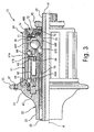
- the bicycle hub assembly 12 basically includes a hub axle 30 and a hub shell 32 with a freewheel 34 for receiving the rear sprockets 28.
- the hub axle 30 and the various parts that are fixedly coupled to rotate with the hub axle 30 are collectively referred to herein as a fixed part of the bicycle component.
- the hub shell 32 and the freewheel 34 form a rotatable hub member (rotatable part) that is mounted on the hub axle 30 for rotation.
- the rotatable hub member (the hub shell 32 and the freewheel 34) is rotatably mounted on the hub axle 30 by a pair of bearing assemblies 36 and 38.
- the freewheel 34 includes a one-way clutch that limits rotation of the hub shell 32 to one rotational direction relative to the hub axle 30.
- the ends of the bicycle hub assembly 12 are sealed by a pair of bicycle sealing assemblies 40R and 40L that are disposed between the hub axle 30 and the rotatable hub member (the hub shell 32 and the freewheel 34).
- the bicycle sealing assembly 40R is disposed between the hub axle 30 and the freewheel 34 that forms a first rotatable end of the rotatable hub member (the hub shell 32 and the freewheel 34).
- the bicycle sealing assembly 40L is disposed between the hub axle 30 and the hub shell 32 that forms a second rotatable end of the rotatable hub member (the hub shell 32 and the freewheel 34).
- the hub axle 30 is a hard, rigid tubular member that has a first or right axle end 41 and a second or left axle end 42 with a center axis A extending between the first and second axle ends 41 and 42.
- the first axle end 41 is provided with external threads 43
- the second axle end 42 is provided with external threads 44.
- a first locking nut 45 is threaded on to the external threads 43 of the first axle end 41
- a second locking nut 46 is threaded on to the external threads 44 of the second axle end 42.
- the hub shell 32 is preferably formed as a one-piece, unitary member. It will be apparent to those skilled in the art that the hub shell 32 can be constructed of any substantially rigid material, such as those materials, which are known in the art.
- the hub shell 32 can be constructed of any suitable metallic material, such as plated steel, stainless steel, aluminum, magnesium or titanium, as well as other non-metallic materials, such as carbon fiber composite, ceramic or plastic.
- the hub shell 32 could be constructed of several pieces of various different materials as need and/or desired.
- the hub shell 32 has a first or right shell end 51 and a second or left shell end 52 with a center tubular portion 53 located therebetween.
- the first and second hub shell ends 51 and 52 are integral formed with the center tubular portion 53 as a one-piece, unitary member.
- the hub shell 32 is a tubular member having an inner tubular surface forming a central interior passage extending between the first and second shell ends 51 and 52.
- the hub axle 30 is coaxially disposed within the central passage of the hub shell 32.
- the first and second bearing 36 and 38 rotatably support the hub shell 32 on the hub axle 30 for rotating the hub shell 32 relative to the hub axle 30.
- the first shell end 51 has a first spoke attachment portion or flange 55 with the freewheel 34 operatively coupled thereto.
- the second shell end 52 has a second spoke attachment portion or flange 56.
- the rim 20 is coupled to the first and second spoke flanges 55 and 56 via the spokes 18.
- the first spoke flange 55 is preferably an annular member with a plurality of first spoke holes 57 (e.g., sixteen in the illustrated embodiment but only one shown in Figure 2 ). In this embodiment, the first spoke holes are equally spaced apart about the imaginary circle that is centered on the axis A.
- the first spoke holes 57 are arranged to receiving the bent ends of the spokes 18.
- the second spoke flange 56 is preferably an annular member with a plurality of second spoke holes 58 for receiving the bent ends of the spokes 18.
- the second spoke holes 58 are equally spaced apart about the imaginary circle that is centered on the center axis A of the hub axle 30.
- the freewheel 34 is operatively coupled between the first axle end 41 of the hub axle 30 and the first shell end 51 of the hub shell 32.
- the freewheel 34 basically includes of a driving (outer) cylinder 61, a driven (inner) cylinder 62, a plurality of spring biased pawls 63, two sets of ball bearings 64 that are axially spaced apart, and a serration main body 65.
- the freewheel 34 is relatively conventional, and thus, will not be discussed or illustrated in detail herein.
- the freewheel 34 of the illustrated embodiment is constructed in accordance with U.S. Patent No. 6,202,813 that is assigned to Shimano, Inc.
- the freewheel 34 is coupled to the hub shell 32 in a relatively conventional manner as will be briefly explained below.
- the sprockets 28 are mounted on the freewheel 34 in a relatively conventional manner such that rotation of the sprockets 28 results in rotation of the freewheel 34. Rotation of the freewheel 34 relative to the hub axle 30 in turn rotates the hub shell 32.
- the driving (outer) cylinder 61 is a tubular member having a roughly cylindrical shape.
- the free end portion of the driving (outer) cylinder 61 forms the first rotatable end of the rotatable hub member (the hub shell 32 and the freewheel 34).
- the outer peripheral surface of the driving (outer) cylinder 61 is provided with a plurality of axially extending splines 61a for fixedly attaching the sprockets 28.
- the splines 61 a non-rotatably couple the sprockets 28 to the outer peripheral surface of the driving cylinder 61.
- the sprockets 28 are mounted to the driving cylinder 61 for transmitting torque to the hub shell 32 via the unidirectional rotation transmission mechanism of the free wheel 34.
- the inner peripheral surface of the interior opening of the driving cylinder 61 has a plurality of ratchet teeth 61b that forms a first part of the unidirectional rotation transmission mechanism of the freewheel 34.
- the inner peripheral surface of the driving cylinder 61 is also rotatably supported on the driven (inner) cylinder 62 by the ball bearings 64.
- the driven (inner) cylinder 62 is inserted and disposed coaxially about the hub axle 30 and coaxially within the driving (outer) cylinder 61.
- the driven (inner) cylinder 62 is fixed to the hub shell 32 by the serration main body 65, which is fixed to the hub sell 32 by interlocking serrations.
- the driven (inner) cylinder 62 has an inner peripheral surface with serrated teeth 62a that are interlocked with external serrations of the serration main body 65.
- the driven (inner) cylinder 62 rotates with the hub shell 32.
- the driven (inner) cylinder 62 is designed to hold the pawls 63 in such a manner as explained, for example, in U.S. Patent No. 6,202,813 .
- Each of the pawls 63 is pivotally mounted on the driven (inner) cylinder 62 and biased to an extended position by a coil torsion-spring 66 such that the pawls 63 normally engage the ratchet teeth 61b of the driving (outer) cylinder 61.
- the pawls 63 and the springs 66 are configured and arranged to operatively couple the driving (outer) cylinder 61 to the driven (inner) cylinder 62 when rotated in a first rotational direction and disconnect the driving (outer) cylinder 61 from the driven (inner) cylinder 62 when rotated in a second rotational direction that is opposite the first rotational direction.
- ratchet teeth 61b together with the pawls 63 and the springs 66 form a unidirectional rotation transmission or one-way clutch that is operatively coupled between the driving cylinder 61 and the driven cylinder 62.
- the driven (inner) cylinder 62 is adapted, by means of the unidirectional rotation transmission mechanism and the ball bearings 64, to freely rotate in one direction relative to the driving cylinder 61.
- the first or right hand bearing assembly 36 is disposed between the first axle end 41 of the hub axle 30 and the freewheel 34 (part of the rotatable hub member) to rotatably support the first shell end 51 of the hub shell 32 and the freewheel 34 on the first axle end 41 of the hub axle 30.
- the first or right hand bearing assembly 36 preferably includes a plurality of first rolling members or balls 67R disposed between a first inner race or cone 68R threadedly coupled to the first axle end 41 of the hub axle 30 and a first outer race or cone 69R threadedly coupled to the driven (inner) cylinder 62 that is fixed to the hub shell 32.
- the first inner cone 68R includes a first inner angular bearing surface contacting one axial side of the first rolling members 67R such that first inner cone 68R contacts and supports each of the first rolling members 67R at an inner peripheral area.
- the first outer race 69R includes a first outer angular bearing surface contacting the first rolling members 67R on an axial side that is opposite from the first inner angular bearing surface such that the first outer race 69R contacts and supports each of the first rolling members 67R at an outer peripheral area.
- the second or left hand bearing assembly 38 is disposed between the second axle end 42 of the hub axle 30 and the second shell end 52 of the hub shell 32 to rotatably support the hub shell 32 on the second axle end 42 of the hub axle 30.
- the second or left hand bearing assembly 38 preferably includes a plurality of second rolling members or balls 67L disposed between a second inner race or cone 68L threadedly coupled to the second axle end 42 of the hub axle 30 and a second outer race or cone 69L threadedly coupled to the interior of the second shell end 52 of the hub shell 32.
- the second inner cone 68L includes a second inner angular bearing surface contacting one axial side of the first rolling members 67L such that the second inner cone 68L contacts and supports each of the first rolling members 67L at an inner peripheral area.
- the second outer race 69L includes a second outer angular bearing surface contacting the first rolling members 67L on an axial side that is opposite from the second inner angular bearing surface such that the second outer race 69L contacts and supports each of the second rolling members 67L at an outer peripheral area.
- the bicycle hub sealing assemblies 40R and 40L are mirror images of each other. In other words, the bicycle hub sealing assemblies 40R and 40L include the same parts, but are installed in the opposite direction. Thus, the same reference numerals will be used for the identical parts of the bicycle hub sealing assemblies 40R and 40L.
- the bicycle hub sealing assembly 40R is disposed between the first axle end 41 of the hub axle 30 and the first rotatable end of the driving (outer) cylinder 61, which constitutes part of the rotatable hub member.
- the bicycle hub sealing assembly 40L is disposed between the second axle end 42 of the hub axle 30 and the second hub shell end 52 of the hub shell 32, which constitutes part of the rotatable hub member.
- Each of the bicycle hub sealing assemblies 40R and 40L includes a first (outer) dust cap 71, a second (inner) dust cap 72, a first (inner) sealing member 73, a second (outer) sealing member 74, and a seal base nut 75.
- the first (outer) dust cap 71 that is located on the right hand side of the hub 12 is fixedly coupled to the first rotatable end of the driving (outer) cylinder 61 (part of the rotatable hub member), while the first (outer) dust cap 71 that is located on the left hand side of the hub 12 is fixedly coupled to the hub shell end 52 of the hub shell 32.
- the first (outer) dust caps 71 are press fitted to the driving (outer) cylinder 61 and the hub shell 32 so that that rotate therewith.
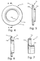
- Each first dust cap 71 is a one-piece, unitary member made of a rigid sheet metal material having a small degree of flexibility.
- the first dust caps 71 are an annular ring shaped members with a uniform cross-sectional profile. In other words, the cross section of the first dust cap 71 at any point preferably has the same cross section as seen in Figure 7 .
- each of the first dust caps 71 basically has a C-shaped cross section that includes an inner axial portion 71a, a middle radial portion 71b and an outer axial portion 71c.
- the inner axial portion 71a is a tubular portion that extends in a generally axial direction.
- the middle radial portion 71b is an annular ring shaped portion that extends in a generally radial direction between the inner axial portion 71 a and the outer axial portion 71 c.
- the outer axial portion 71 c is a tubular portion that extends in a generally axial direction and directly contacts the inner peripheral surface of the driving cylinder 61.
- the first dust cap 71 rotates with the freewheel 34.
- the inner axial portion 71a of the first dust cap 71 is configured and arranged to overlap with the second dust cap 73 as explained below.
- the inner axial portion 71a of the first dust cap 71 has a radially inwardly facing that contacts the first (inner) sealing member 73 to create a seal therebetween.
- the outer axial portion 71c of the first dust cap 71 has a radially inwardly facing that contacts the second (outer) sealing member 73 to create a seal therebetween.
- the second (inner) dust caps 72 are fixedly coupled to the first and second axle ends 41 and 42 of the hub axle 30 by the first and second locking nuts 45 and 46 that are threaded onto the external threads 43 and 44 of the first and second axle ends 41 and 42, respectively.
- the second dust caps 72 rotate with the hub axle 30.
- the second dust caps 72 are a one-piece, unitary members made of a rigid sheet metal material having a small degree of flexibility.
- each second dust cap 72 is an annular ring shaped member with a uniform cross-sectional profile.
- the cross section of the second dust cap 72 at any point preferably has the same cross section as seen in Figure 11 .
- each of the second dust caps 72 basically has an L-shaped cross section that includes an outer axial portion 72a and a radial portion 72b.
- the outer axial portion 72a is a tubular portion that extends in a generally axial direction.
- the radial portion 72b is an annular ring shaped portion that extends in a generally radial direction from one end of the outer axial portion 72a.
- the inner axial portion 71a of the first dust cap 71 is arranged to overlap with the outer axial portion 72a of the second dust cap 72.
- the inner axial portion 71 a of the first dust cap 71 is arranged below the outer axial portion 72a of the second dust cap 72 as seen in Figure 11 .
- the outer axial portion 72a of the second dust cap 72 has a radially outwardly facing surface that is stepped to form an annular abutment portion or surface 72c and a contact portion or surface 72d that contacts the second sealing member 74 to create a seal therebetween.
- the annular abutment portion 72c is configured and arranged to prevent axial movement of the second sealing member 74 along the contact surface 72d of the second dust cap 72.
- the abutment portion 72c is preferably an angled abutment surface that is angled approximately thirty degrees relative to a line parallel to the center axis A of the bicycle sealing assembly 40R.
- each of the first (inner) sealing members 73 is slideably disposed between a corresponding one of the first dust caps 71 (rotational part) and a corresponding one of the seal base nuts 75 (fixed part).
- the first sealing members 73 can be configured and arranged to contact either the seal base nut 75 or the second dust cap 72 to form a seal therebetween.
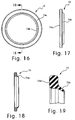
- Each first sealing member 73 is a one-piece, unitary member made of a resilient flexible sealing material such as an elastomeric material having good sealing qualities.
- the first sealing members 73 are an annular ring shaped member with a uniform cross-sectional profile. In other words, the cross section of each first sealing member 73 at any point preferably has the same cross section as seen in Figure 15 .
- each of the first sealing members 73 has a cross sectional shape that includes a main body portion 73a, an outer sealing flange portion 73b and an inner sealing flange portion 73c.
- the outer sealing flange portion 73b has an outer seal surface that directly contacts the radially inwardly facing surface of the inner axial portion 71a of the first dust cap 71 to form a seal therebetween.
- the inner sealing flange portion 73c has an inner seal surface that directly contacts the radially outwardly facing surface of the seal base nut 75 (fixed part) to form a seal therebetween.
- the first sealing member 73 is configured and arranged relative to the first dust cap 71, the seal base nut 75 (fixed part) and the second dust cap 72 to float in an axial direction.
- the second (outer) sealing members 74 are disposed between a corresponding one of the second dust caps 72 (fixed part) and a corresponding one of the first dust caps 71 (rotational part) to form a second seal therebetween.
- the second sealing member 74 can be configured and arranged to contact either the first dust cap 71 or the driving cylinder 61 to form a seal therebetween.
- the second sealing member 74 is a one-piece, unitary member made of a resilient flexible sealing material such as an elastomeric material having good sealing qualities.
- the second sealing member 74 is an annular ring shaped member with a uniform cross-sectional profile. In other words, the cross section of the second sealing member 74 at any point preferably has the same cross section as seen in Figure 19 .
- each of the second sealing members 74 has a cross sectional shape that includes a main body portion 74a with an inner sealing flange portion 74b.
- the main body portion 74a of the second sealing member 74 is press fitted into the first dust cap 71 such that an outer seal surface of the main body portion 74a of the second sealing member 74 contacts the radially inwardly facing surface of the outer axial portion 71c of the first dust cap 71 to create a seal therebetween.
- the inner sealing flange portion 74b contacts a radially outwardly facing portion of the contact surface 72d of the second dust cap 72 such that an inner seal surface of the inner sealing flange portion 74b of the second sealing member 74 contacts the radially outwardly facing surface of the outer axial portion 72a of the second dust cap 72 to create a seal therebetween.
- the free end or tip of the inner sealing flange portion 74b contacts the annular abutment portion 72c to prevent axial movement of the second sealing member 74 along the contact surface 72d of the second dust cap 72.
- the seal base nuts 75 are threaded on to the external threads 43 and 44 of the first and second axle ends 41 and 42.
- Each of the seal base nuts 75 has a step shaped outer peripheral surface for receiving the first sealing member 73 thereon.
- the step shaped outer peripheral surface of the seal base nut 75 is configured and arrange such that the first sealing member 73 can float relative in an axial direction relative to the first dust cap 71, the seal base nut 75 (fixed part) and the second dust cap 72.
- a rear hub 212 is illustrated in accordance with a second embodiment.
- the parts of the second embodiment that are identical to the parts of the first embodiment will be given the same reference numerals as the parts of the first embodiment.
- the descriptions of the parts of the second embodiment that are identical to the parts of the first embodiment may be omitted for the sake of brevity.
- the rear hub 212 is identical to the rear hub 12, except that the sealing assemblies 40R and 40L of the first embodiment have been replaced with a pair of modified sealing assemblies 240R and 240L in this second embodiment. More specifically, the seal base nuts 75 have been eliminated in the sealing assemblies 240R and 240L of the rear hub 212, and the dust caps 72 and the seals 73 have been each replaced with an inner dust cap 272 and an inner seal 273 in the rear hub 212.
- each of the sealing assemblies 240R and 240L of the rear hub 212 includes the first (outer) dust cap 71, the second (inner) dust cap 272, the first (inner) sealing member 273, and the second (outer) sealing member 74.
- the inner seal 273 directly contacts the inner dust cap 272 and the outer dust cap 71 to create a seal therebetween.
- each inner dust cap 272 is a one-piece, unitary member made of a rigid sheet metal material having a small degree of flexibility.
- the inner dust caps 272 are an annular ring shaped member with a uniform cross-sectional profile. In other words, the cross section of the inner dust cap 272 at any point preferably has the same cross section.
- the inner dust cap 272 basically has a C-shaped cross section that includes an outer axial portion 272a, a radial portion 272b and an inner axial portion 272c.
- the outer axial portion 272a is a tubular portion that extends in a generally axial direction.
- the radial portion 272b is an annular ring shaped portion that extends in a generally radial direction from between the outer axial portion 272a and the inner axial portion 272c.
- the inner axial portion 71a of the outer dust cap 71 is arranged to overlap with the outer axial portion 272a of the second dust cap 272.
- the inner axial portion 71a of the outer dust cap 71 is arranged below the outer axial portion 272a of the inner dust cap 272.
- the inner axial portion 272c is a tubular portion that extends in a generally axial direction from the inner end of the radial portion 272b with its inner surface contacting the hub axle 30. If desired, the axial portion 272c can be threaded to engage the threads of the hub axle 30.
- the outer axial portion 272a of the inner dust cap 272 has a radially outwardly facing surface that is stepped to form an annular abutment portion or surface 272d and a contact portion or surface 272e that contacts the outer sealing member 74 to create a seal therebetween.
- the annular abutment portion 272d is configured and arranged to prevent axial movement of the outer sealing member 74 along the contact surface 272e of the inner dust cap 272.
- the abutment portion 272d is preferably an angled abutment surface that is angled approximately thirty degrees relative to a line parallel to the center axis A of the bicycle sealing assembly 240R or 240L.
- the inner sealing member 273 is slideably disposed between the outer dust cap 71 (rotational part) and the inner dust cap 272 (fixed part).
- the inner sealing member 273 is a one-piece, unitary member made of a resilient flexible sealing material such as an elastomeric material having good sealing qualities.
- the inner sealing member 273 is an annular ring shaped member with a uniform cross-sectional profile.
- the cross section of the inner sealing member 273 at any point preferably has the same cross section.
- the inner sealing member 273 has a cross sectional shape that includes a main body portion 273a, an outer sealing flange portion 273b and an inner sealing flange portion 273c.
- the outer sealing flange portion 273b has an outer seal surface that directly contacts the radially inwardly facing surface of the inner axial portion 71a of the outer dust cap 71 to form a seal therebetween.
- the inner sealing flange portion 273c has an inner seal surface that directly contacts the radially outwardly facing surface of the inner dust cap 272 (fixed part) to form a seal therebetween.
- the inner sealing member 273 is configured and arranged relative to the outer dust cap 71 and the inner dust cap 272 (fixed part) to float in an axial direction.
- a rear hub 312 is illustrated in accordance with a third embodiment.
- the parts of the third embodiment that are identical to the parts of the first embodiment will be given the same reference numerals as the parts of the first embodiment.
- the descriptions of the parts of the third embodiment that are identical to the parts of the first embodiment may be omitted for the sake of brevity.
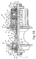
- the rear hub 312 is identical to the rear hub 12, except that the sealing assemblies 40R and 40L of the first embodiment have been replaced with a pair of modified sealing assemblies 340R and 340L in this third embodiment. More specifically, the outer seals 74 have been each replaced with an outer seal 374 in the rear hub 312.
- each of the sealing assemblies 340R and 340L of the rear hub 312 includes the first (outer) dust cap 71, the second (inner) dust cap 72, the first (inner) sealing member 73, and the second (outer) sealing member 374.
- the outer seal 374 directly contacts the driving cylinder 61 and the inner dust cap 72 to create a seal therebetween.
- the outer sealing members 374 are one-piece, unitary members made of a resilient flexible sealing material such as an elastomeric material having good sealing qualities.
- the outer sealing members 374 are annular ring shaped members with a uniform cross-sectional profile.
- the cross section of the outer sealing member 374 at any point preferably has the same cross section.
- Each outer sealing member 374 has a cross sectional shape that includes a main body portion 374a with an inner sealing flange portion 374b as seen in Figure 23 .
- the main body portion 374a of the second sealing member 374 is press fitted into the driving cylinder 61 on the right hand side of the hub 312 such that an outer seal surface of the main body portion 374a of the outer sealing member 374 contacts the radially inwardly facing surface of the driving cylinder 61 to create a seal therebetween.
- the main body portion 374a of the second sealing member 374 is press fitted into the second end 52 of the hub shell 32 on the left hand side of the hub 312 such that an outer seal surface of the main body portion 374a of the outer sealing member 374 contacts the radially inwardly facing surface of the second end 52 of the hub shell 32 to create a seal therebetween.
- the inner sealing flange portions 374b contact a radially outwardly facing portion of a corresponding one of the contact surface 72d of the corresponding inner dust cap 72 such that an inner seal surface of the inner sealing flange portion 374b of the inner sealing member 374 contacts the radially outwardly facing surface of the corresponding outer axial portion 72a of the corresponding inner dust cap 72 to create a seal therebetween.
- the free end or tip of the inner sealing flange portion 374b contacts the annular abutment portion 72c to prevent axial movement of the second sealing member 374 along the contact surface 72d of the corresponding inner dust cap 72.
- the following directional terms “inner, outer, forward, rearward, above, downward, vertical, horizontal, below and transverse” as well as any other similar directional terms refer to those directions of a bicycle equipped with the present invention. Accordingly, these terms, as utilized to describe the present invention should be interpreted relative to a bicycle equipped with the present invention. Also the terms of degree such as “substantially”, “about” and “approximately” as used herein mean a reasonable amount of deviation of the modified term such that the end result is not significantly changed. These terms should be construed as including a deviation of at least ⁇ 5% of the modified term if this deviation would not negate the meaning of the word it modifies.
Landscapes
- Engineering & Computer Science (AREA)
- Mechanical Engineering (AREA)
- Sealing Of Bearings (AREA)
- Sealing Devices (AREA)
- Sealing Using Fluids, Sealing Without Contact, And Removal Of Oil (AREA)
- Sealing With Elastic Sealing Lips (AREA)
Claims (20)
- Dispositif d'étanchéité (40R, 40L) pour bicyclette comprenant :un premier capuchon anti-poussière (71) configuré et agencé pour être fixé sur une partie rotative d'une bicyclette ;un second capuchon anti-poussière (72, 272) configuré et agencé pour être fixé sur une partie fixe d'une bicyclette ;un premier élément d'étanchéité (73, 273) disposé entre le premier capuchon anti-poussière (71) et la partie fixe ou le second capuchon anti-poussière (72, 272) pour former un premier joint d'étanchéité entre eux ; etun second élément d'étanchéité (74, 374) disposé entre le second capuchon anti-poussière (72, 272) et le premier capuchon anti-poussière (71) ou la partie rotative pour former un second joint d'étanchéité entre eux ;caractérisé en ce que le premier élément d'étanchéité (73, 273) est disposé de manière coulissante entre le premier capuchon anti-poussière (71) et l'un parmi le premier capuchon anti-poussière (72, 272) et la partie fixe de la bicyclette, et est configuré et agencé de manière flottante dans une direction axiale par rapport au premier capuchon anti-poussière (71), la partie fixe de la bicyclette et le second capuchon anti-poussière (72, 272).
- Dispositif d'étanchéité (40R, 40L) pour bicyclette selon la revendication 1, dans lequel :le premier élément d'étanchéité (73, 273) est en contact avec une surface orientée radialement vers l'intérieur du premier capuchon anti-poussière (71) ; etle second élément d'étanchéité (74, 374) est en contact avec une surface orientée radialement vers l'extérieur du second capuchon anti-poussière (72, 272).
- Dispositif d'étanchéité (40R, 40L) pour bicyclette selon la revendication 1 ou 2, dans lequel :le second capuchon anti-poussière (72, 272) comprend une partie de butée (72c, 272d) en contact avec le second élément d'étanchéité (74, 374) et agencé pour empêcher le mouvement axial du second élément d'étanchéité (74, 374) le long d'une surface de contact du second capuchon anti-poussière (72, 272).
- Dispositif d'étanchéité (40R, 40L) pour bicyclette selon l'une quelconque des revendications précédentes, dans lequel :le premier élément d'étanchéité (73, 273) est configuré et agencé pour être en contact avec un écrou de base de joint d'étanchéité (75) qui forme une partie de la partie fixe de la bicyclette.
- Dispositif d'étanchéité (40R, 40L) pour bicyclette selon l'une quelconque des revendications précédentes, dans lequel :le premier capuchon anti-poussière (71) comprend une partie interne s'étendant dans une direction axiale ; etle second capuchon anti-poussière (72, 272) comprend une partie externe s'étendant dans une direction axiale et agencée pour chevaucher la partie interne du premier capuchon anti-poussière (71).
- Dispositif d'étanchéité (40R, 40L) pour bicyclette selon l'une quelconque des revendications précédentes, dans lequel :le second élément d'étanchéité (74, 374) est monté à la presse sur le premier capuchon anti-poussière (71) ou la partie rotative.
- Dispositif d'étanchéité (40R, 40L) pour bicyclette selon l'une quelconque des revendications précédentes, dans lequel :le second élément d'étanchéité (74, 374) comprend une surface de joint d'étanchéité externe en contact avec la face orientée radialement vers l'intérieur du premier capuchon anti-poussière (71) et une surface de joint d'étanchéité interne en contact avec la surface orientée radialement vers l'extérieur du second capuchon anti-poussière (72, 272).
- Dispositif d'étanchéité (40R, 40L) pour bicyclette selon la revendication 3, dans lequel :le premier élément d'étanchéité (73, 273) comprend une surface de joint d'étanchéité externe en contact avec la surface orientée radialement vers l'intérieur du premier capuchon anti-poussière (71).
- Dispositif d'étanchéité (40R, 40L) pour bicyclette selon la revendication 8, dans lequel :le premier capuchon anti-poussière (71) comprend une partie interne s'étendant dans une direction axiale avec la surface orientée radialement vers l'intérieur formée sur celle-ci,le second capuchon anti-poussière (72, 272) comprend une partie externe s'étendant dans une direction axiale avec la surface orientée radialement vers l'extérieur formée sur celle-ci, etla partie interne du premier capuchon anti-poussière (71) étant agencée pour chevaucher la partie externe du second capuchon anti-poussière (72, 272).
- Dispositif d'étanchéité (40R, 40L) pour bicyclette selon la revendication 8 ou 9, dans lequel :la partie interne du premier capuchon anti-poussière (71) est agencée au-dessous de la partie externe du second capuchon anti-poussière (72, 272).
- Dispositif d'étanchéité (40R, 40L) pour bicyclette selon l'une quelconque des revendications précédentes, dans lequel :les premier et second capuchons anti-poussière (71 ; 72, 272) sont réalisés avec un matériau en tôle.
- Dispositif d'étanchéité (40R, 40L) pour bicyclette selon la revendication 3, dans lequel :la partie de butée (72c, 272d) a une surface de butée coudée qui est coudée approximativement à 30 degrés par rapport à une ligne parallèle à un axe central (A) du dispositif d'étanchéité (40R, 40L ; 240R, 240L ; 340R, 340L).
- Dispositif d'étanchéité (40R, 40L) pour bicyclette selon l'une quelconque des revendications précédentes, dans lequel :le premier élément d'étanchéité (73, 273) est en contact avec le premier capuchon anti-poussière (71) et la partie fixe pour former le premier joint d'étanchéité entre eux.
- Dispositif d'étanchéité (40R, 40L) pour bicyclette selon la revendication 13, dans lequel :le second élément d'étanchéité (74, 374) est en contact avec le second capuchon anti-poussière (72, 272) et le premier capuchon anti-poussière (71) pour former le second joint d'étanchéité entre eux.
- Dispositif d'étanchéité (40R, 40L) pour bicyclette selon l'une quelconque des revendications 1 à 12, dans lequel :le second élément d'étanchéité (74, 374) est en contact avec le second capuchon anti-poussière (72, 272) et le premier capuchon anti-poussière (71) pour former le second joint d'étanchéité entre eux.
- Dispositif d'étanchéité (40R, 40L) pour bicyclette selon l'une quelconque des revendications 1 à 12, dans lequel :le premier élément d'étanchéité (73, 273) est en contact avec le premier capuchon anti-poussière (71) et le second capuchon anti-poussière (72, 272) pour former le premier joint d'étanchéité entre eux.
- Dispositif d'étanchéité (40R, 40L) pour bicyclette selon la revendication 16, dans lequel :le second élément d'étanchéité (74, 374) est en contact avec le second capuchon anti-poussière (72, 272) et la partie rotative pour former le second joint d'étanchéité entre eux.
- Composant de bicyclette comprenant :une partie fixe avec un axe central (A) ;une partie rotative ayant une surface tubulaire interne formant un passage central, la partie fixe étant disposée de manière rotative à l'intérieur du passage central de la partie rotative ; etun dispositif d'étanchéité (40R, 40L) pour bicyclette selon l'une quelconque des revendications 1 à 17.
- Composant de bicyclette selon la revendication 18, dans lequel la partie fixe est un essieu de moyeu (30), et la partie rotative est une roue libre (34).
- Composant de bicyclette selon la revendication 18, dans lequel :la partie fixe est un essieu de moyeu (30) et la partie rotative est une coque de moyeu (32).
Applications Claiming Priority (2)
| Application Number | Priority Date | Filing Date | Title |
|---|---|---|---|
| US781934 | 2004-02-20 | ||
| US10/781,934 US7029075B2 (en) | 2004-02-20 | 2004-02-20 | Bicycle hub sealing assembly |
Publications (3)
| Publication Number | Publication Date |
|---|---|
| EP1566287A2 EP1566287A2 (fr) | 2005-08-24 |
| EP1566287A3 EP1566287A3 (fr) | 2006-12-27 |
| EP1566287B1 true EP1566287B1 (fr) | 2008-11-19 |
Family
ID=34711856
Family Applications (1)
| Application Number | Title | Priority Date | Filing Date |
|---|---|---|---|
| EP04021002A Expired - Lifetime EP1566287B1 (fr) | 2004-02-20 | 2004-09-03 | Dispositif d'étanchéité pour moyeu de bicyclette |
Country Status (6)
| Country | Link |
|---|---|
| US (1) | US7029075B2 (fr) |
| EP (1) | EP1566287B1 (fr) |
| JP (1) | JP2005231617A (fr) |
| CN (1) | CN1657808A (fr) |
| DE (1) | DE602004017833D1 (fr) |
| TW (1) | TW200530055A (fr) |
Cited By (1)
| Publication number | Priority date | Publication date | Assignee | Title |
|---|---|---|---|---|
| EP2452865B1 (fr) | 2010-11-12 | 2016-08-10 | Shimano Inc. | Structure de support de pignon |
Families Citing this family (51)
| Publication number | Priority date | Publication date | Assignee | Title |
|---|---|---|---|---|
| US7011600B2 (en) | 2003-02-28 | 2006-03-14 | Fallbrook Technologies Inc. | Continuously variable transmission |
| JP4974896B2 (ja) | 2004-10-05 | 2012-07-11 | フォールブルック テクノロジーズ インコーポレイテッド | 連続可変変速機 |
| DE602005003547T2 (de) * | 2005-01-27 | 2008-10-23 | Shimano Inc., Sakai | Fahrradantriebsnabe |
| EP1695841B1 (fr) * | 2005-02-28 | 2008-01-23 | Shimano Inc. | Couvercle pour l'ensemble de moyeu et transmission d'une bicyclette |
| US7191884B2 (en) * | 2005-02-28 | 2007-03-20 | Shimano Inc. | Bicycle hub |
| US7461904B2 (en) * | 2005-06-17 | 2008-12-09 | Shimano Inc. | Bicycle hub sealing structure |
| JP4157883B2 (ja) * | 2005-07-29 | 2008-10-01 | 株式会社シマノ | 自転車用内装変速ハブのキャップ部材 |
| EP3521119A1 (fr) | 2005-10-28 | 2019-08-07 | Fallbrook Intellectual Property Company LLC | Véhicule comprenant une transmission à variation continue |
| CN101495777B (zh) | 2005-11-22 | 2011-12-14 | 福博科技术公司 | 无级变速器 |
| CN102226464B (zh) | 2005-12-09 | 2013-04-17 | 福博科技术公司 | 一种用于变速器的轴向力产生机构 |
| EP1811202A1 (fr) | 2005-12-30 | 2007-07-25 | Fallbrook Technologies, Inc. | Transmission à variation continue |
| JP2007290606A (ja) * | 2006-04-26 | 2007-11-08 | Shimano Inc | 自転車用ハブ |
| US8480529B2 (en) | 2006-06-26 | 2013-07-09 | Fallbrook Intellectual Property Company Llc | Continuously variable transmission |
| US8738255B2 (en) | 2007-02-01 | 2014-05-27 | Fallbrook Intellectual Property Company Llc | Systems and methods for control of transmission and/or prime mover |
| US20100093479A1 (en) | 2007-02-12 | 2010-04-15 | Fallbrook Technologies Inc. | Continuously variable transmissions and methods therefor |
| EP2122198B1 (fr) | 2007-02-16 | 2014-04-16 | Fallbrook Intellectual Property Company LLC | Procede et ensemble |
| WO2008131353A2 (fr) | 2007-04-24 | 2008-10-30 | Fallbrook Technologies Inc. | Entraînements de traction électrique |
| US8641577B2 (en) | 2007-06-11 | 2014-02-04 | Fallbrook Intellectual Property Company Llc | Continuously variable transmission |
| KR20100046166A (ko) | 2007-07-05 | 2010-05-06 | 폴브룩 테크놀로지즈 인크 | 연속 가변 변속기 |
| TW200916339A (en) * | 2007-09-06 | 2009-04-16 | Aleksandr Sherman | Bicycle wheel |
| CN101861482B (zh) | 2007-11-16 | 2014-05-07 | 福博科知识产权有限责任公司 | 用于变速传动装置的控制器 |
| CN105197177B (zh) | 2007-12-21 | 2019-05-07 | 福博科知识产权有限责任公司 | 自动传动装置及用于其的方法 |
| CA2942806C (fr) | 2008-02-29 | 2018-10-23 | Fallbrook Intellectual Property Company Llc | Transmissions en continu ou variables infiniment et methodes associees |
| US8317651B2 (en) | 2008-05-07 | 2012-11-27 | Fallbrook Intellectual Property Company Llc | Assemblies and methods for clamping force generation |
| JP5457438B2 (ja) | 2008-06-06 | 2014-04-02 | フォールブルック インテレクチュアル プロパティー カンパニー エルエルシー | 無限可変変速機、及び無限可変変速機用の制御システム |
| CN102084155B (zh) | 2008-06-23 | 2014-06-11 | 福博科知识产权有限责任公司 | 无级变速器 |
| WO2010017242A1 (fr) | 2008-08-05 | 2010-02-11 | Fallbrook Technologies Inc. | Procédés de commande d'une transmission et/ou d'une machine motrice |
| US8469856B2 (en) | 2008-08-26 | 2013-06-25 | Fallbrook Intellectual Property Company Llc | Continuously variable transmission |
| US8167759B2 (en) | 2008-10-14 | 2012-05-01 | Fallbrook Technologies Inc. | Continuously variable transmission |
| KR101005259B1 (ko) | 2008-12-09 | 2011-01-04 | 안왕기 | 자전거용 허브 |
| DK2419658T3 (da) | 2009-04-16 | 2014-01-13 | Fallbrook Ip Co Llc | Statoranordning og forskydningsmekanisme for en kontinuerlig variabel transmission |
| JP5116779B2 (ja) * | 2010-01-08 | 2013-01-09 | 書偉 林 | 自転車ハブの製造方法及びその製品 |
| US8512195B2 (en) | 2010-03-03 | 2013-08-20 | Fallbrook Intellectual Property Company Llc | Infinitely variable transmissions, continuously variable transmissions, methods, assemblies, subassemblies, and components therefor |
| US8888643B2 (en) | 2010-11-10 | 2014-11-18 | Fallbrook Intellectual Property Company Llc | Continuously variable transmission |
| US8393794B1 (en) * | 2011-09-12 | 2013-03-12 | Shimano Inc. | Bicycle bottom bracket assembly |
| KR20140114065A (ko) | 2012-01-23 | 2014-09-25 | 폴브룩 인텔렉츄얼 프로퍼티 컴퍼니 엘엘씨 | 무한 가변 변속기, 연속 가변 변속기, 방법, 조립체, 서브조립체 및 그 부품 |
| US8979387B2 (en) * | 2012-09-11 | 2015-03-17 | Shimano Inc. | Bicycle hub assembly |
| US9085197B2 (en) * | 2012-09-28 | 2015-07-21 | Shimano Inc. | Bicycle hub kit |
| CN105324299B (zh) | 2013-04-19 | 2018-10-12 | 福博科知识产权有限责任公司 | 无级变速器 |
| CN103738114B (zh) * | 2013-12-31 | 2016-08-17 | 久裕交通器材(深圳)有限公司 | 一种自行车花鼓密封结构 |
| US20160136996A1 (en) * | 2014-11-16 | 2016-05-19 | Robert Sweeting | Single Shell Bicycle Hub with Enlarged Drive-Side Flange |
| US10047861B2 (en) | 2016-01-15 | 2018-08-14 | Fallbrook Intellectual Property Company Llc | Systems and methods for controlling rollback in continuously variable transmissions |
| CN109154368B (zh) | 2016-03-18 | 2022-04-01 | 福博科知识产权有限责任公司 | 无级变速器、系统和方法 |
| US10023266B2 (en) | 2016-05-11 | 2018-07-17 | Fallbrook Intellectual Property Company Llc | Systems and methods for automatic configuration and automatic calibration of continuously variable transmissions and bicycles having continuously variable transmissions |
| US10995806B2 (en) | 2017-07-26 | 2021-05-04 | Dt Swiss Inc. | Hub, in particular for bicycles |
| EP3275691B1 (fr) * | 2016-07-26 | 2019-05-15 | DT Swiss AG | Moyeu, en particulier pour vélos |
| US10625540B2 (en) | 2017-07-26 | 2020-04-21 | Dt Swiss Inc. | Hub, in particular for bicycles |
| US11208171B2 (en) * | 2017-09-21 | 2021-12-28 | Veselin Mandaric | Drive assembly for a bicycle |
| US11215268B2 (en) | 2018-11-06 | 2022-01-04 | Fallbrook Intellectual Property Company Llc | Continuously variable transmissions, synchronous shifting, twin countershafts and methods for control of same |
| IT201900000247A1 (it) * | 2019-01-09 | 2020-07-09 | Skf Ab | Gruppo mozzo-ruota per veicoli |
| US11174922B2 (en) | 2019-02-26 | 2021-11-16 | Fallbrook Intellectual Property Company Llc | Reversible variable drives and systems and methods for control in forward and reverse directions |
Family Cites Families (18)
| Publication number | Priority date | Publication date | Assignee | Title |
|---|---|---|---|---|
| JPS59102504U (ja) | 1982-12-27 | 1984-07-10 | 株式会社シマノ | 自転車用ハブ |
| US4850670A (en) * | 1983-08-29 | 1989-07-25 | American Telephone And Telegraph Company, At&T Bell Laboratories | Optical fiber connector comprising drawn glass tubes |
| JPS63169303U (fr) | 1987-04-25 | 1988-11-04 | ||
| DE8800382U1 (de) * | 1988-01-15 | 1988-02-25 | FAG Kugelfischer Georg Schäfer KGaA, 8720 Schweinfurt | Dichtung |
| US5024364A (en) * | 1989-02-13 | 1991-06-18 | Federal-Mogul Corporation | Unitized oil seal and method of making a unitized oil seal |
| JP2593889Y2 (ja) * | 1993-04-30 | 1999-04-19 | 株式会社シマノ | 自転車用ハブ軸 |
| JP3460166B2 (ja) | 1996-02-02 | 2003-10-27 | 株式会社シマノ | 自転車用フリーホイールの爪音消し機構 |
| DE19847673A1 (de) | 1998-10-15 | 2000-04-20 | Dt Swiss Ag | Nabe, insbesondere für Fahrräder u. dgl. |
| JP4781535B2 (ja) | 1998-12-08 | 2011-09-28 | デーテー・スイス・アーゲー | 自転車等のハブ |
| DE19856626B4 (de) | 1998-12-08 | 2008-10-09 | Dt Swiss Ag | Nabe und Laufrad, insbesondere für Fahrräder |
| US6352314B1 (en) * | 2000-01-31 | 2002-03-05 | Shimano Inc. | Bicycle hub for disc brake |
| US6511133B1 (en) * | 2000-01-31 | 2003-01-28 | Shimano Inc. | Bicycle hub with spoke seal |
| DE20013400U1 (de) | 2000-08-03 | 2000-12-21 | Kun Teng Industry Co., Ltd., Ta-Ya Hsiang, Taichung | Naben-Kraftübertragungsmechanismus mit einem Dichtungselement |
| US6386644B2 (en) | 2000-08-08 | 2002-05-14 | Kun Teng Industry Co., Ltd. | Bicycle hub provided with a seal member for preventing entrance of dust |
| US6523659B2 (en) * | 2000-12-11 | 2003-02-25 | Shimano Inc. | Bicycle hub with tight connection ratchet and detachable freewheel |
| DE20101377U1 (de) | 2001-01-26 | 2001-03-29 | Kun Teng Industry Co., Ltd., Ta-Ya Hsiang, Taichung | Mit einem Dichtungselement zur Verhinderung des Eindringens von Staub versehene Fahrradnabe |
| US20030042101A1 (en) | 2001-08-28 | 2003-03-06 | Shu-Chen Juan | Freewheel hub device |
| US7059686B2 (en) * | 2003-01-22 | 2006-06-13 | Shimano Inc. | Bicycle hub |
-
2004
- 2004-02-20 US US10/781,934 patent/US7029075B2/en not_active Expired - Fee Related
- 2004-08-25 CN CN2004100682365A patent/CN1657808A/zh active Pending
- 2004-09-03 EP EP04021002A patent/EP1566287B1/fr not_active Expired - Lifetime
- 2004-09-03 DE DE602004017833T patent/DE602004017833D1/de not_active Expired - Lifetime
- 2004-10-20 TW TW093131863A patent/TW200530055A/zh unknown
-
2005
- 2005-01-20 JP JP2005012849A patent/JP2005231617A/ja not_active Withdrawn
Cited By (2)
| Publication number | Priority date | Publication date | Assignee | Title |
|---|---|---|---|---|
| EP2452865B1 (fr) | 2010-11-12 | 2016-08-10 | Shimano Inc. | Structure de support de pignon |
| EP2452865B2 (fr) † | 2010-11-12 | 2025-07-16 | Shimano Inc. | Structure de support de pignon |
Also Published As
| Publication number | Publication date |
|---|---|
| US7029075B2 (en) | 2006-04-18 |
| TW200530055A (en) | 2005-09-16 |
| EP1566287A3 (fr) | 2006-12-27 |
| DE602004017833D1 (de) | 2009-01-02 |
| CN1657808A (zh) | 2005-08-24 |
| EP1566287A2 (fr) | 2005-08-24 |
| US20050184580A1 (en) | 2005-08-25 |
| JP2005231617A (ja) | 2005-09-02 |
Similar Documents
| Publication | Publication Date | Title |
|---|---|---|
| EP1566287B1 (fr) | Dispositif d'étanchéité pour moyeu de bicyclette | |
| EP1213217B1 (fr) | Moyeu de bicyclette | |
| US6886894B2 (en) | Bicycle hub axle | |
| US6488603B2 (en) | Freewheel for a bicycle | |
| EP1213158B1 (fr) | Moyeu de bicyclette | |
| US6669306B1 (en) | Bicycle hub axle assembly | |
| US6382381B1 (en) | Bicycle hub assembly | |
| EP1495879B1 (fr) | Moyeu de bicyclette extérieur et moyeu de bicyclette | |
| US7059686B2 (en) | Bicycle hub | |
| US9193416B2 (en) | Bicycle sprocket support assembly | |
| EP1213157B1 (fr) | Moyeu de bicyclette avec entretoise filetée et roue libre démontable | |
| US7562604B2 (en) | Bicycle chain wheel structure | |
| US10315727B2 (en) | Bicycle rear sprocket assembly | |
| US20020067068A1 (en) | Bicycle hub with spacer and detachable freewheel | |
| EP1695842B1 (fr) | Moyeu de bicyclette | |
| EP1122096A2 (fr) | Moyeu de bicyclette pour frein à disque | |
| EP1733899A2 (fr) | Dispositif d'étanchéité pour moyeu de bicyclette | |
| US20040183361A1 (en) | Rear hub for bicycle |
Legal Events
| Date | Code | Title | Description |
|---|---|---|---|
| PUAI | Public reference made under article 153(3) epc to a published international application that has entered the european phase |
Free format text: ORIGINAL CODE: 0009012 |
|
| AK | Designated contracting states |
Kind code of ref document: A2 Designated state(s): AT BE BG CH CY CZ DE DK EE ES FI FR GB GR HU IE IT LI LU MC NL PL PT RO SE SI SK TR |
|
| AX | Request for extension of the european patent |
Extension state: AL HR LT LV MK |
|
| RAP1 | Party data changed (applicant data changed or rights of an application transferred) |
Owner name: SHIMANO COMPONENTS (MALAYSIA) SDN. BHD. Owner name: SHIMANO INC. |
|
| PUAL | Search report despatched |
Free format text: ORIGINAL CODE: 0009013 |
|
| AK | Designated contracting states |
Kind code of ref document: A3 Designated state(s): AT BE BG CH CY CZ DE DK EE ES FI FR GB GR HU IE IT LI LU MC NL PL PT RO SE SI SK TR |
|
| AX | Request for extension of the european patent |
Extension state: AL HR LT LV MK |
|
| 17P | Request for examination filed |
Effective date: 20070117 |
|
| AKX | Designation fees paid |
Designated state(s): DE NL |
|
| 17Q | First examination report despatched |
Effective date: 20070817 |
|
| GRAP | Despatch of communication of intention to grant a patent |
Free format text: ORIGINAL CODE: EPIDOSNIGR1 |
|
| GRAS | Grant fee paid |
Free format text: ORIGINAL CODE: EPIDOSNIGR3 |
|
| GRAA | (expected) grant |
Free format text: ORIGINAL CODE: 0009210 |
|
| AK | Designated contracting states |
Kind code of ref document: B1 Designated state(s): DE NL |
|
| REF | Corresponds to: |
Ref document number: 602004017833 Country of ref document: DE Date of ref document: 20090102 Kind code of ref document: P |
|
| PLBE | No opposition filed within time limit |
Free format text: ORIGINAL CODE: 0009261 |
|
| STAA | Information on the status of an ep patent application or granted ep patent |
Free format text: STATUS: NO OPPOSITION FILED WITHIN TIME LIMIT |
|
| 26N | No opposition filed |
Effective date: 20090820 |
|
| PGFP | Annual fee paid to national office [announced via postgrant information from national office to epo] |
Ref country code: NL Payment date: 20090921 Year of fee payment: 6 |
|
| REG | Reference to a national code |
Ref country code: NL Ref legal event code: V1 Effective date: 20110401 |
|
| PG25 | Lapsed in a contracting state [announced via postgrant information from national office to epo] |
Ref country code: NL Free format text: LAPSE BECAUSE OF NON-PAYMENT OF DUE FEES Effective date: 20110401 |
|
| PGFP | Annual fee paid to national office [announced via postgrant information from national office to epo] |
Ref country code: DE Payment date: 20180821 Year of fee payment: 15 |
|
| REG | Reference to a national code |
Ref country code: DE Ref legal event code: R119 Ref document number: 602004017833 Country of ref document: DE |
|
| PG25 | Lapsed in a contracting state [announced via postgrant information from national office to epo] |
Ref country code: DE Free format text: LAPSE BECAUSE OF NON-PAYMENT OF DUE FEES Effective date: 20200401 |