EP1565680B1 - Direktgesteuertes proportional druckbegrenzungsventil - Google Patents
Direktgesteuertes proportional druckbegrenzungsventil Download PDFInfo
- Publication number
- EP1565680B1 EP1565680B1 EP03779685A EP03779685A EP1565680B1 EP 1565680 B1 EP1565680 B1 EP 1565680B1 EP 03779685 A EP03779685 A EP 03779685A EP 03779685 A EP03779685 A EP 03779685A EP 1565680 B1 EP1565680 B1 EP 1565680B1
- Authority
- EP
- European Patent Office
- Prior art keywords
- armature
- valve
- pressure limiting
- valve cone
- cone
- Prior art date
- Legal status (The legal status is an assumption and is not a legal conclusion. Google has not performed a legal analysis and makes no representation as to the accuracy of the status listed.)
- Expired - Lifetime
Links
- 239000011888 foil Substances 0.000 claims description 4
- 230000001105 regulatory effect Effects 0.000 claims 2
- 230000002093 peripheral effect Effects 0.000 description 4
- 230000001681 protective effect Effects 0.000 description 3
- 238000010276 construction Methods 0.000 description 2
- 238000006073 displacement reaction Methods 0.000 description 2
- 239000012530 fluid Substances 0.000 description 2
- 238000004519 manufacturing process Methods 0.000 description 2
- 230000000284 resting effect Effects 0.000 description 2
- 239000004809 Teflon Substances 0.000 description 1
- 229920006362 Teflon® Polymers 0.000 description 1
- 230000015572 biosynthetic process Effects 0.000 description 1
- 238000002788 crimping Methods 0.000 description 1
- 238000013016 damping Methods 0.000 description 1
- 238000011161 development Methods 0.000 description 1
- 230000018109 developmental process Effects 0.000 description 1
- 238000007598 dipping method Methods 0.000 description 1
- 238000005516 engineering process Methods 0.000 description 1
- 230000002349 favourable effect Effects 0.000 description 1
- 230000003116 impacting effect Effects 0.000 description 1
- 239000000696 magnetic material Substances 0.000 description 1
- 239000000463 material Substances 0.000 description 1
- 238000007789 sealing Methods 0.000 description 1
- 239000011800 void material Substances 0.000 description 1
Images
Classifications
-
- F—MECHANICAL ENGINEERING; LIGHTING; HEATING; WEAPONS; BLASTING
- F16—ENGINEERING ELEMENTS AND UNITS; GENERAL MEASURES FOR PRODUCING AND MAINTAINING EFFECTIVE FUNCTIONING OF MACHINES OR INSTALLATIONS; THERMAL INSULATION IN GENERAL
- F16K—VALVES; TAPS; COCKS; ACTUATING-FLOATS; DEVICES FOR VENTING OR AERATING
- F16K31/00—Actuating devices; Operating means; Releasing devices
- F16K31/02—Actuating devices; Operating means; Releasing devices electric; magnetic
- F16K31/06—Actuating devices; Operating means; Releasing devices electric; magnetic using a magnet, e.g. diaphragm valves, cutting off by means of a liquid
- F16K31/0686—Braking, pressure equilibration, shock absorbing
- F16K31/0693—Pressure equilibration of the armature
-
- G—PHYSICS
- G05—CONTROLLING; REGULATING
- G05D—SYSTEMS FOR CONTROLLING OR REGULATING NON-ELECTRIC VARIABLES
- G05D16/00—Control of fluid pressure
- G05D16/20—Control of fluid pressure characterised by the use of electric means
- G05D16/2006—Control of fluid pressure characterised by the use of electric means with direct action of electric energy on controlling means
- G05D16/2013—Control of fluid pressure characterised by the use of electric means with direct action of electric energy on controlling means using throttling means as controlling means
- G05D16/2022—Control of fluid pressure characterised by the use of electric means with direct action of electric energy on controlling means using throttling means as controlling means actuated by a proportional solenoid
Definitions
- the invention relates to a directly controlled and proportionally adjustable pressure limiting valve according to the preamble of patent claim 1.
- Such pressure relief valves are used, for example, as proportionally adjustable pressure relief valves.
- a directly controlled pressure limiting valve in which an armature of a proportional magnet acts on a valve cone via a tappet.
- the valve cone is guided with a sliding guide in the valve housing and the plunger resting against the valve cone is supported in the armature and passes through a guide disk of the valve housing.
- valve cone is supported directly in the anchor.
- the armature is provided with a through hole, which is closed at the rear by a disc on which the valve cone is supported by a ball.
- the valve cone is guided with a certain radial clearance in the armature, so that an axial offset between the armature and the valve cone by slight inclination of the valve plug is compensated.
- the invention has the object, a direct-controlled prop.
- a pressure relief valve in which a reliable function is ensured with low manufacturing technology and device complexity.
- the valve cone of the pressure relief valve is axially centered gimbals supported on the armature, wherein the radial clearance between the valve cone and the anchor is so large that the valve cone in a movement relative to the anchor does not rub against this and pressure fluid can flow largely freely between the armature and poppet.
- the term "gimbal” is to be understood as a support of the valve cone, which allows its inclination with respect to the anchor axis.
- Such a pressure relief valve according to the invention has, on the one hand, the advantages of the prior art described at the outset and an axial offset between armature and valve seat is compensated in a simple manner.
- the fixed to the housing ensures that the valve plug is guided with sufficient accuracy relative to the valve seat to be able to mount the valve seat without impacting the valve plug and thus without damage.
- Another advantage of this solution is that the housing-fixed guide a throttle gap for flowing into the armature space and from the armature space pressure medium is formed and thereby the movements of the valve cone are damped. Due to the centered gimbal support of the valve cone at the anchor, the radial position of one end of the valve cone is fixed. The other end is centered by the valve seat when the valve is closed and by the fluid flow when the valve is open, thus ensuring that the valve plug does not rub against the housing-fixed guide.
- the axial support of the valve cone in the armature via a ball which thus forms a kind of all-round articulated support and thus allows a tilting of the valve cone to some extent.
- the support of the valve cone in the axial direction takes place in the central region of the armature.
- the support of the valve cone is particularly simple when an axially extending blind hole is executed in the anchor, which receives the valve cone in sections. Its back is then indirectly or directly supported at the bottom of the blind hole.
- the bottom of the blind hole and / or the adjacent end face of the valve cone with - preferably V-shaped - be provided oblique surfaces which bear tangentially on the outer circumference of the ball.
- the valve cone has a cylindrical portion which adjoins the conical end, with which the valve cone can sit on the valve seat.
- the diameter of the cylindrical portion is determined by the desired maximum diameter of the tapered end and extends through the housing-fixed guide into the anchor, so that the cylindrical portion for grinding has a favorable length.
- the blind hole in the anchor is stepped to accommodate in the wider area said portion of the valve cone readily with radial play and in the narrower range a commercial ball, such as a ball bearing ball with a press fit.
- the valve cone with a portion of smaller diameter immersed in the narrower area of the blind hole.
- the armature preferably has one or more throttle bores, via which pressure medium can flow during the axial displacement of the armature between a valve cone-side armature space and a rear armature space.
- the anchor is supported by a foil.
- the construction of the seat valve is particularly simple when the valve cone is flying, that is guided freely displaceable in the armature.
- the valve cone was always biased by a spring in the armature in the opening or closing direction.
- the device complexity can be further reduced if a centering projection for centering a control spring is provided on the back of the anchor.
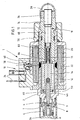
- the pressure relief valve 1 has a valve housing 2, in which a valve cone 4 is guided axially displaceable.
- a seat body 6 is inserted through which an axial port A and a valve seat 8 are formed.
- This seat body 6 can be used for example by press fitting into the housing.
- a radial outlet or tank connection T is formed by an oblique bore star 9.
- the actuation of the valve cone 4 by means of a proportional solenoid 10 which is attached axially to the valve housing 2.
- the proportional magnet 10 has an integrally formed with the valve housing 2 pole tube 12, in which an armature 14 is mounted. At this the valve cone 8 is supported.
- the armature 14 is by means of a control spring 16 in the closing direction of the valve cone eighth biased.
- the bias of the control spring 16 can be changed by means of an adjusting device 18.
- the proportional magnet 10 further has a pole tube 12 encompassing coil housing 20 in which a magnetic coil 22 is received.
- the power supply of the proportional magnet 10 via in Fig. 1 overhead terminals 24, which are combined in a connector body and placed on the coil housing 20.
- the pressure limiting valve 1 designed as a screw-in valve is provided with a connection protection cap 26 placed on the valve housing 2 and a protective cap 28 placed on a lock nut 76 of the adjustment device.
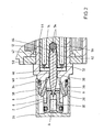
- valve housing Details of the valve housing will be explained below with reference to the enlarged view of Figure 2.
- the seat body 6 has an approximately cup-shaped structure, wherein in a bottom 30 of the valve seat 8 is formed.
- the port A is formed by an axial bore 32 of the seat body 6, which opens into the valve seat 8.
- the outer end face of the bottom 30 is bounded by a receiving bore 34 of the valve housing 2, a tank space 36 in which the extending to the outer peripheral surface of the valve body 2 Schrägbohrungsstern 9 (terminal T) opens.
- the remote from the seat body 6 end face of the receiving bore 34 is formed by a housing web 38 which is penetrated by a coaxial with the receiving bore 34 extending guide bore 40.
- the pole tube 12 is attached to the valve housing 2.
- This can - as in the described embodiment - be designed in one piece with the valve housing 2 or as a separate attached component.
- the armature 14 is guided with its outer circumference in an anchor hole 42 of the pole tube 12.
- the inner circumferential wall of the anchor bore 42 is lined with a foil 44, for example of Teflon material.
- This film 44 forms a sliding bearing for the armature 14, so that it is easily displaceable within the pole tube 12. In order to prevent jamming of the armature 14, this is performed with a certain play, which may be, for example, 1/10 mm.
- the armature 14 divides the receiving space of the pole tube 12 (see also FIG. 1) into a valve cone-side armature space 46 and a rear armature space 48. These two armatures 46, 48 are connected by means of throttle bores 50, which are axially parallel to the valve axis through the armature 14 in the illustrated embodiment extend through.
- the armature has valve seat side a blind hole 52 which extends from the left in Figure 2 end face of the armature 14 to approximately in the axially central region.
- the bottom of the blind hole 52 is provided with V-shaped mutually arranged inclined surfaces 54 on which a ball 56 is supported.
- the valve cone 4 is supported.
- the valve cone 4 has a dargestellen in the closed position in sections in the seat body 6 dipping cone 58, which is seated with an outer peripheral portion on the valve seat 8.
- the cone 58 is adjoined by a cylindrical guide section 60, which passes through the guide bore 40.
- An immersed in the armature 14 end portion 62 is radially stepped back, wherein the outer diameter of this end portion 62 corresponds approximately to the diameter of the ball 56.
- spheres of a conventional ball bearing are used as a ball. These are characterized by high strength and good wear resistance.
- the contact surface of the end portion 62 to the ball 56 is also provided with inclined abutment surfaces 64.
- inclined surfaces 54 and the inclined bearing surfaces 64 is a centering of the ball 56 with respect to the blind hole 52 and correspondingly a centering of the end portion 62 of the valve cone 4 with respect to the ball 56th
- this game is less than the prescribed game between the end portion 62 and the armature 14.
- the game in the region of the guide portion 60 is selected so that in the pole tube 12 befindliches Pressure medium in the idle state does not escape through the annular gap between the guide portion 60 and the guide bore 40 therethrough and the pole tube, so to speak, idles.
- a centering projection 66 is formed on the rear side of the armature 14, onto which a contact disk is placed and which serves for centering the control spring 16 resting against the contact disk. This dips into the inner bore 68 of a closure piece 70 inserted into the pole tube 12. This is positively connected to the pole tube 12, wherein in the illustrated embodiment, the connection is made by crimping.
- a locking screw 72 is screwed over which the coil housing 20 is pressed axially against a shoulder of the valve housing 2.
- a clamping bolt 74 is screwed, via which the bias of the control spring 16 is adjustable.
- the spring-side end portion of the clamping bolt 74 is also provided with a centering pin 66 for the control spring.
- a lock nut 76 is screwed, which is brought to fix the position of the clamping bolt 74 in abutment with the adjacent end face of the closure piece 70.
- the protective cap 28 is placed on the lock nut 76.
- sealing elements are provided on the outer circumference of the closure piece 70 and on the outer circumference of the clamping bolt.
- the pole tube 12 is further divided by a ring 78 of non-magnetic material.
- the above-described construction is characterized by a very simple structural design with small dead spaces, so that when filling the pole tube 12, the formation of air pockets (air pockets) is avoided.
- the seat body 6 is pressed into the valve housing 2. Before this Einspressvorgang the poppet 4 is already in its illustrated position. Due to the comparatively small radial play between the guide section 60 of the valve cone 4 and the bore 40, the conical tip threads securely into the seat body 6. The compensation of tolerances between the position of the armature and the position of the seat body is due to the radial clearance between the valve cone 4 and the armature 14 by a slight tilting of the valve cone.
- the pole tube 12 In its basic position, the pole tube 12 is completely filled with pressure medium. If the proportional magnet 10 is now energized, the armature is displaced to the right by the resulting magnetic forces against the force of the control spring 16 and the valve cone 4 is lifted off the valve seat 8 by the pressure acting on the connection A. The armature 14 and the poppet 4 are in response to the force of the control spring 16, the force applied by the proportional magnet 10 magnetic force and the acting compressive forces in a control position, wherein pressure medium from port A via the controlled depending on the armature travel 14 throttle gap in the Pressure chamber 36 and from there via the oblique hole star 9 to the tank port T can flow out.
- the armature 14 When Stromlosschalt the solenoid valve, the armature 14 is moved by the force of the control spring 16 back to the left, wherein pressure medium from the armature chamber 46 is displaced via the throttle holes 50 in the rear armature chamber 48 - the poppet is then moved back accordingly to the left until it the valve seat 8 is seated, wherein pressure medium is sucked through the above-described annular gap.
- the pressure relief valve 1 is "normally closed” executed.
- the pressure relief valve could also be “normally open” executed, d. h.,
- the valve cone 4 would be biased in the basic position in the opening direction.
- a proportionally adjustable pressure limiting valve in which a valve cone by means of an armature of a proportional solenoid is actuated.
- the valve cone is gimbal-supported in the armature.
- An additional guidance of the valve cone via a housing-side guide, wherein the clearance between the valve cone and the housing-side guide is designed to be less than the clearance between the valve cone and the armature.
Description
- Die Erfindung betrifft ein direktgesteuertes und proportional verstellbares Druckbegrenzungsventil gemäß dem Oberbegriff des Patentanspruchs 1.
- Derartige Druckbegrenzungsventile werden beispielsweise als proportional verstellbare Druckbegrenzungsventile eingesetzt. In der WO 00/50794 A1 ist ein direktgesteuertes Druckbegrenzungsventil offenbart, bei dem ein Anker eines Proportionalmagneten über einen Stößel auf einen Ventilkegel wirkt. Der Ventilkegel ist mit einer Gleitführung im Ventilgehäuse geführt und der am Ventilkegel anliegende Stößel ist im Anker abgestützt und durchsetzt eine Führungsscheibe des Ventilgehäuses. Problematisch bei dieser Lösung ist, dass es im Fall des Achsversatzes zwischen dem Ventilsitz und dem Ventilkegel möglich ist, dass das Druckbegrenzungsventil nicht mehr zuverlässig schließt.
- In der DE 196 25 349 wird eine diesbezüglich verbesserte Lösung vorgeschlagen, bei der der Ventilkegel direkt im Anker abgestützt ist. Hierzu ist der Anker mit einer Durchgangsbohrung versehen, die rückseitig durch eine Scheibe verschlossen ist, an der der Ventilkegel über eine Kugel abgestützt ist. Der Ventilkegel ist mit einem gewissen Radialspiel im Anker geführt, so dass ein Achsversatz zwischen dem Anker und dem Ventilkegel durch leichte Schrägstellung des Ventilkegels ausgleichbar ist.
- Eine ähnliche Lösung ist auch in der DE 32 44 840 C2 offenbart.
- Es zeigte sich jedoch, dass auch diese Varianten mit einem mit Spiel im Anker gelagerten Ventilkörper mit hoher Präzision gefertigt und zusammengefügt werden müssen, um ein zuverlässiges Schließen zu gewährleisten und eine Schädigung des Ventilsitzes zu verhindern.
- Demgegenüber liegt der Erfindung die Aufgabe zugrunde, ein direktgesteuertes prop. Druckbegrenzungsventil zu schaffen, bei dem mit geringem fertigungstechnischen und vorrichtungstechnischen Aufwand eine zuverlässige Funktion gewährleistet ist.
- Diese Aufgabe wird durch ein direktgesteuertes prop. Druckbegrenzungsventil mit dem Merkmal des Patentanspruchs 1 gelöst.
- Erfindungsgemäß ist der Ventilkegel des Druckbegrenzungsventil axial zentriert kardanisch am Anker abgestützt, wobei das Radialspiel zwischen dem Ventilkegel und dem Anker so groß ist, dass der Ventilkegel bei einer Bewegung relativ zum Anker nicht an diesem reibt und Druckmittel weitgehend frei zwischen Anker und Ventilkegel fliessen kann. Es ist zwischen dem Anker und dem Ventilsitz eine gehäusefeste Führung für den Ventilkegel vorhanden, die mit geringerem Radialspiel als das ankerseitige Radialspiel ausgebildet ist.
- Unter dem Begriff "kardanisch" soll eine Abstützung des Ventilkegels verstanden werden, die dessen Schrägstellung mit Bezug zur Ankerachse ermöglicht.
- Ein derartiges erfindungsgemäßes Druckbegrenzungsventil weist zum einen die Vorteile des eingangs beschriebenen Standes der Technik auf und ein Achsversatz zwischen Anker und Ventilsitz auf einfache Weise ausgeglichen ist. Andererseits wird durch die gehäusefeste Führung sichergestellt, dass der Ventilkegel mit Bezug zum Ventilsitz exakt genug geführt ist, um den Ventilsitz ohne Anstossen an den Ventilkegel und damit ohne Beschädigung montieren zu können. Ein weiterer Vorteil dieser Lösung besteht darin, dass durch die gehäusefeste Führung ein Drosselspalt für in den Ankerraum und aus dem Ankerraum fliessendes Druckmittel gebildet wird und dadurch die Bewegungen des Ventilkegels gedämpft werden. Durch die zentrierte kardanische Abstützung des Ventilkegels am Anker ist die radiale Lage des einen Endes des Ventilkegels festgelegt. Das andere Ende wird bei geschlossenem Ventil durch den Ventilsitz und bei offenem Ventil durch die Druckmittelströmung zentriert, so dass sichergestellt ist, dass der Ventilkegel nicht an der gehäusefesten Führung reibt.
- Bei einer bevorzugten Variante der Erfindung erfolgt die Axialabstützung des Ventilkegels im Anker über eine Kugel, die somit eine Art allseitige gelenkige Abstützung ausbildet und somit ein Schrägstellen des Ventilkegels in gewissem Maße erlaubt.
- Besonders bevorzugt wird es, wenn die Abstützung des Ventilkegels in Axialrichtung gesehen im Mittelbereich des Ankers erfolgt. Durch diese Maßnahme wird der Achsversatz des im Anker mit Bezug zum Ventilkegel bei einem Kippen des Ankers aufgrund seines Spiels im Polrohr minimiert.
- Die Abstützung des Ventilkegels ist besonders einfach, wenn im Anker eine axial verlaufende Sacklochbohrung ausgeführt ist, die den Ventilkegel abschnittsweise aufnimmt. Dessen Rückseite ist dann am Boden der Sachlochbohrung mittelbar oder unmittelbar abgestützt.
- Zur Verbesserung der Abstützung über eine Kugel kann der Boden der Sacklochbohrung und/oder die benachbarte Stirnfläche des Ventilkegels mit - vorzugsweise V-förmigen - Schrägflächen versehen sein, die an dem Außenumfang der Kugel tangential anliegen.
- Bei einer weiteren vorteilhaften Ausgestaltung besitzt der Ventilkegel einen zylindrischen Abschnitt, der sich an das kegelförmige Ende anschließt, mit dem der Ventilkegel auf dem Ventilsitz aufsitzen kann. Der Durchmesser des zylindrischen Abschnitts ist durch den gewünschten maximalen Durchmesser des kegelförmigen Endes bestimmt und erstreckt sich durch die gehäusefeste Führung hindurch bis in den Anker hinein, so dass der zylindrische Abschnitt für eine schleifende Bearbeitung günstige Länge hat. Die Sacklochbohrung im Anker ist gestuft, um im weiteren Bereich den besagten Abschnitt des Ventilkegels ohne weiteres mit Radialspiel und um im engeren Bereich eine handelsübliche Kugel, beispielsweise eine Kugellagerkugel, mit Presssitz aufnehmen zu können. Vorteilhafterweise taucht der Ventilkegel mit einem Abschnitt geringeren Durchmessers in den engeren Bereich der Sacklochbohrung ein.
- Der Anker weist vorzugsweise eine oder mehrere Drosselbohrungen auf, über die Druckmittel bei der Axialverschiebung des Ankers zwischen einem ventilkegelseitigen Ankerraum und einem rückwärtigen Ankerraum strömen kann.
- Bei einem vorteilhaften Ausführungsbeispiel wird der Anker über eine Folie gelagert.
- Der Aufbau des Sitzventils ist besonders einfach, wenn der Ventilkegel fliegend, das heißt frei verschiebbar im Anker geführt ist. Bei den eingangs genannten Lösungen war der Ventilkegel stets über eine Feder im Anker in Öffnungs- oder Schließrichtung vorgespannt.
- Der vorrichtungstechnische Aufwand lässt sich weiter verringern, wenn am Anker rückseitig ein Zentriervorsprung zur Zentrierung einer Regelfeder vorgesehen ist.
- Sonstige vorteilhafte Weiterbildungen der Erfindung sind Gegenstand weiterer Unteransprüche.
- Im Folgenden wird ein bevorzugtes Ausführungsbeispiel der Erfindung anhand schematischer Zeichnungen näher erläutert. Es zeigen:
- Figur 1 einen Schnitt durch ein erfindungsgemäßes direktgesteuertes Druckbegrenzungsventil und
- Figur 2 eine Detaildarstellung des Druckbegrenzungsventils aus Figur 1.
- Gemäß dem in Fig. 1 dargestellten Längsschnitt hat das Druckbegrenzungsventil 1 ein Ventilgehäuse 2, in dem ein Ventilkegel 4 axial verschiebbar geführt ist. In das Ventilgehäuse 2 ist ein Sitzkörper 6 eingesetzt, durch den ein axialer Anschluss A und ein Ventilsitz 8 ausgebildet sind. Dieser Sitzkörper 6 kann beispielsweise durch Presspassung in das Gehäuse eingesetzt werden. Im Ventilgehäuse 2 ist ein radialer Ablauf - oder Tankanschluss T durch einen Schrägbohrungsstern 9 ausgebildet. Die Betätigung des Ventilkegels 4 erfolgt mittels eines Proportionalmagneten 10, der axial an das Ventilgehäuse 2 angesetzt ist. Der Proportionalmagnet 10 hat ein einstückig mit dem Ventilgehäuse 2 ausgeführtes Polrohr 12, in dem ein Anker 14 gelagert ist. An diesem ist der Ventilkegel 8 abgestützt. Der Anker 14 ist mittels einer Regelfeder 16 in Schließrichtung des Ventilkegels 8 vorgespannt. Die Vorspannung der Regelfeder 16 lässt sich mittels einer Stelleinrichtung 18 verändern. Der Proportionalmagnet 10 hat des Weiteren ein das Polrohr 12 umgreifendes Spulengehäuse 20, in dem eine Magnetspule 22 aufgenommen ist. Die Stromversorgung des Proportionalmagneten 10 erfolgt über in Fig. 1 oben liegende Anschlüsse 24, die in einem Anschlusskörper zusammengefasst und auf das Spulengehäuse 20 aufgesetzt sind.
- Im ausgelieferten Zustand ist das als Einschraubventil ausgeführte Druckbegrenzungsventil 1 mit einer auf das Ventilgehäuse 2 aufgesetzten Anschlussschutzkappe 26 und einer auf eine Kontermutter 76 der Stelleinrichtung aufgesetzten Schutzkappe 28 versehen.
- Einzelheiten des Ventilgehäuses werden im Folgenden anhand der vergrößerten Darstellung gemäß Figur 2 erläutert.
- Demgemäß hat der Sitzkörper 6 einen etwa tassenförmigen Aufbau, wobei in einem Boden 30 der Ventilsitz 8 ausgebildet ist. Der Anschluss A wird durch eine Axialbohrung 32 des Sitzkörpers 6 ausgebildet, die im Ventilsitz 8 mündet.
- Die außenliegende Stirnfläche des Bodens 30 begrenzt mit einer Aufnahmebohrung 34 des Ventilgehäuses 2 einen Tankraum 36, in dem der sich zur Außenumfangsfläche des Ventilkörpers 2 erstreckende Schrägbohrungsstern 9 (Anschluss T) mündet.
- Die vom Sitzkörper 6 entfernte Stirnfläche der Aufnahmebohrung 34 wird von einem Gehäusesteg 38 gebildet, der von einer sich koaxial zur Aufnahmebohrung 34 erstreckenden Führungsbohrung 40 durchsetzt ist.
- Im Bereich des Gehäusestegs 38 ist an das Ventilgehäuse 2 das Polrohr 12 angesetzt. Dieses kann - wie beim beschriebenen Ausführungsbeispiel - einstückig mit dem Ventilgehäuse 2 oder als eigenes angesetztes Bauteil ausgeführt sein.
- Der Anker 14 ist mit seinem Außenumfang in einer Ankerbohrung 42 des Polrohrs 12 geführt. Zur Verminderung der Reibung zwischen Anker 14 und Polrohr 12 ist die Innenumfangswandung der Ankerbohrung 42 mit einer Folie 44, beispielsweise aus Teflonmaterial ausgekleidet. Diese Folie 44 bildet ein Gleitlager für den Anker 14, so dass dieser innerhalb des Polrohrs 12 leicht verschiebbar ist. Um ein Klemmen des Ankers 14 zu verhindern, ist dieser mit einem gewissen Spiel geführt, das beispielsweise 1/10 mm betragen kann.
- Der Anker 14 teilt den Aufnahmeraum des Polrohrs 12 (siehe auch Figur 1) in einen ventilkegelseitigen Ankerraum 46 und einen rückseitigen Ankerraum 48. Diese beiden Ankerräume 46, 48 sind mittels Drosselbohrungen 50 verbunden, die sich beim dargestellten Ausführungsbeispiel achsparallel zur Ventilachse durch den Anker 14 hindurch erstrecken.
- Der Anker hat ventilsitzseitig eine Sacklochbohrung 52, die sich von der in Figur 2 linken Stirnfläche des Ankers 14 bis etwa in den axial mittleren Bereich hinein erstreckt. Der Boden der Sacklochbohrung 52 ist mit V-förmig zueinander angeordneten Schrägflächen 54 versehen, an denen eine Kugel 56 abgestützt ist. An dieser Kugel 56 ist ihrerseits der Ventilkegel 4 abgestützt. Bei dem in Figur 2 dargestellten Ausführungsbeispiel hat der Ventilkegel 4 einen in der dargestellen Schließstellung abschnittsweise in den Sitzkörper 6 eintauchenden Kegel 58, der mit einem Außenumfangsabschnitt auf dem Ventilsitz 8 aufsitzt. An den Kegel 58 schließt sich ein zylinderförmiger Führungsabschnitt 60 an, der die Führungsbohrung 40 durchsetzt. Ein in den Anker 14 eingetauchter Endabschnitt 62 ist radial zurückgestuft, wobei der Außendurchmesser dieses Endabschnitts 62 etwa dem Durchmesser der Kugel 56 entspricht. Zur Verminderung der Produktionskosten werden als Kugel 56 Kugeln eines herkömmlichen Kugellagers verwendet. Diese zeichnen sich durch eine hohe Festigkeit und gute Verschleißwiderstandsfähigkeit aus.
- Die Anlagefläche des Endabschnitts 62 an die Kugel 56 ist ebenfalls mit schrägen Anlageflächen 64 versehen. Durch die Schrägflächen 54 und die schrägen Anlageflächen 64 erfolgt eine Zentrierung der Kugel 56 mit Bezug zur Sacklochbohrung 52 und entsprechend eine Zentrierung des Endabschnittes 62 des Ventilkegels 4 mit Bezug zur Kugel 56.
- Zwischen dem Endabschnitt 62 und der Innenumfangsbohrung der Sacklochbohrung 52 ist ein gewisses Spiel vorgesehen, das eine leichte Schrägstellung des Endabschnitts 62 und damit des Ventilkegels 4 oder des Ankers 14 ermöglicht. Durch dieses Kippen des Ventilkegels 4 oder des Ankers 14 kann ein Achsversatz zwischen dem Anker 14 und dem Ventilsitz 8 ausgeglichen werden, dabei wirkt die Kugel 56 praktisch als Gelenklager, um das herum der Ventilkegel 4 relativ zum Anker kippt.
- Auch zwischen dem Führungsabschnitt 60 und der Innenumfangswandung der Führungsbohrung 40 ist ein Spiel vorgesehen, dieses Spiel ist jedoch geringer als das vorgeschriebene Spiel zwischen dem Endabschnitt 62 und dem Anker 14. Das Spiel im Bereich des Führungsabschnittes 60 ist so gewählt, dass im Polrohr 12 befindliches Druckmittel im Ruhezustand nicht durch den Ringspalt zwischen dem Führungsabschnitt 60 und der Führungsbohrung 40 hindurch austritt und das Polrohr sozusagen leerläuft.
- Gemäss Figur 1 ist an der Rückseite des Ankers 14 ein Zentriervorsprung 66 ausgebildet, auf den eine Anlagescheibe aufgesetzt ist und der zur Zentrierung der an der Anlagescheibe anliegenden Regelfeder 16 dient. Diese taucht in die Innenbohrung 68 eines in das Polrohr 12 eingesetzten Verschlussstückes 70 ein. Dieses ist formschlüssig mit dem Polrohr 12 verbunden, wobei beim dargestellten Ausführungsbeispiel die Verbindung durch Bördeln hergestellt ist.
- Auf den Aussenumfang des Verschlussstücks 70 ist eine Sicherungsschraube 72 aufgeschraubt über die das Spulengehäuse 20 gegen eine Schulter des Ventilgehäuses 2 axial gedrückt wird.
- In die mit einem Gewinde versehene Innenbohrung 68 ist ein Spannbolzen 74 eingeschraubt, über den die Vorspannung der Regelfeder 16 einstellbar ist. Der federseitige Endabschnitt des Spannbolzens 74 ist ebenfalls mit einem Zentrierzapfen 66 für die Regelfeder versehen. Auf einen aus dem Verschlussstück 70 hervorstehenden Endabschnitt des Spannbolzens 74 ist eine Kontermutter 76 aufgeschraubt, die zur Lagefixierung des Spannbolzens 74 in Anlage an die benachbarte Stirnfläche des Verschlussstücks 70 gebracht wird. Die Schutzkappe 28 ist auf die Kontermutter 76 aufgesetzt. Zur Abdichtung des Polrohrs sind am Aussenumfang des Verschlussstückes 70 sowie am Aussenumfang des Spannbolzen 74 Dichtungselemente vorgesehen. Das Polrohr 12 wird des Weiteren durch einen Ring 78 aus nicht magnetischem Material unterteilt.
- Die vorbeschriebene Konstruktion zeichnet sich durch einen sehr einfachen konstruktiven Aufbau mit geringen Toträumen auf, so dass beim Befüllen des Polrohrs 12 die Entstehung von Lufteinschlüssen (Luftpolstern) vermieden wird.
- Bei der Montage des Druckbegrenzungsventils 1 wird der Sitzkörper 6 in das Ventilgehäuse 2 eingepreßt. Vor diesem Einspressvorgang befindet sich der Ventilkegel 4 bereits in seiner dargestellten Position. Aufgrund des vergleichsweise geringen Radialspiels zwischen dem Führungsabschnitt 60 des Ventilkegels 4 und der Bohrung 40 fädelt die Kegelspitze sicher in den Sitzkörper 6 ein. Der Ausgleich von Toleranzen zwischen der Lage des Ankers und der Lage des Sitzkörpers erfolgt aufgrund des Radialspiels zwischen dem Ventilkegel 4 und dem Anker 14 durch ein leichtes Verkippen des Ventilkegels.
- In seiner Grundposition ist das Polrohr 12 vollständig mit Druckmittel gefüllt. Wird nun der Proportionalmagnet 10 bestromt, so wird der Anker durch die entstehenden Magnetkräfte gegen die Kraft der Regelfeder 16 nach rechts verschoben und der Ventilkegel 4 durch den am Anschluss A wirkenden Druck vom Ventilsitz 8 abgehoben. Der Anker 14 und der Ventilkegel 4 stellen sich in Abhängigkeit von der Kraft der Regelfeder 16, der vom Proportionalmagneten 10 aufgebrachten Magnetkraft und von den wirkenden Druckkräften in eine Regelposition ein, wobei Druckmittel vom Anschluss A über den in Abhängigkeit vom Ankerweg 14 aufgesteuerten Drosselspalt in den Druckraum 36 und von dort über den Schrägbohrungsstern 9 zum Tankanschluss T hin abströmen kann. Bei der Axialverschiebung des Ankers 14 nach rechts (gegen die Kraft der Regelfeder 16) wird das sich im rückwärtigen Ankerraum 48 befindliche Druckmittel über die Drosselbohrungen 50 in den Ankerraum 46 verdrängt. Da das Leervolumen dieses Ankerraums 46 geringer als dasjenige des rückwärtigen Ankerraums 48 ist, muss Druckmittel durch den Ringspalt zwischen dem Führungsabschnitt 60 und der Führungsbohrung 40 vom Ankerraum 46 in den Druckraum 36 verdrängt werden. Diese Drosselung in dem Ringspalt bewirkt bei Druckänderungen in den Ankerräumen 46, 48 eine Dämpfung der entsprechenden Ventilkegelbewegung.
- Beim Stromlosschalten des Magnetventils wird der Anker 14 durch die Kraft der Regelfeder 16 wieder nach links verschoben, wobei Druckmittel aus dem Ankerraum 46 über die Drosselbohrungen 50 in den rückwärtigen Ankerraum 48 verdrängt wird - der Ventilkegel wird dann entsprechend wieder nach links verschoben, bis er auf dem Ventilsitz 8 aufsitzt, wobei Druckmittel durch den vorbeschriebenen Ringspalt nachgesaugt wird.
- Bei dem dargestellten Ausführungsbeispiel ist das Druckbegrenzungsventil 1 "stromlos geschlossen" ausgeführt. Selbstverständlich könnte das Druckbegrenzungsventil auch "stromlos geöffnet" ausgeführt sein, d. h., der Ventilkegel 4 wäre in der Grundposition in Öffnungsrichtung vorgespannt.
- Offenbart ist ein proportional verstellbares Druckbegrenzungsventil bei dem ein Ventilkegel mittels eines Ankers eines Proportionalmagneten betätigbar ist. Der Ventilkegel ist kardanisch im Anker abgestützt. Eine zusätzliche Führung des Ventilkegels erfolgt über eine gehäuseseitige Führung, wobei das Spiel zwischen Ventilkegel und gehäuseseitiger Führung geringer als das Spiel zwischen Ventilkegel und Anker ausgeführt ist.
-
- 1
- Druckbegenzungsventil
- 2
- Ventilgehäuse
- 4
- Ventilkegel
- 6
- Sitzkörper
- 8
- Ventilsitz
- 9
- Schrägbohrungsstern
- 10
- Proportionalmagnet
- 12
- Polrohr
- 14
- Anker
- 16
- Regelfeder
- 18
- Stelleinrichtung
- 20
- Spulengehäuse
- 22
- Magnetspule
- 24
- Anschlüsse
- 26
- Anschlussschutzkappe
- 28
- Schutzkappe
- 30
- Boden
- 32
- Axialbohrung
- 34
- Aufnahmebohrung
- 36
- Tankraum
- 38
- Gehäusesteg
- 40
- Führungsbohrung
- 42
- Ankerbohrung
- 44
- Folie
- 46
- Ankerraum
- 48
- rückseitiger Ankerraum
- 50
- Drosselbohrung
- 52
- Sacklochbohrung
- 54
- Schrägflächen
- 56
- Kugel
- 58
- Kegel
- 60
- Führungsabschnitt
- 62
- Endabschnitt
- 64
- Anlagefläche
- 66
- Zentrierzapfen
- 68
- Innenbohrung
- 70
- Verschlusstück
- 72
- Sicherungsschraube
- 74
- Spannbolzen
- 76
- Kontermutter
Claims (11)
- Direkt gesteuertes und propotional verstellbares Druckbegrenzungsventil mit einem in einem Ventilgehäuse (2) ausgebildeten Ventilsitz (8) und mit einem Ventilkegel (4), die in einer Regelstellung des Ventilkegels (4) einen Drosselspalt begrenzen, über den ein Eingangsanschluss (A) mit einem Ausgangsanschluss (T) verbunden ist, wobei der Ventilkegel (4) in einem bauchgelagerten Anker (14) eines Proportionalmagneten (10) mit Radialspiel abgestützt ist, gekennzeichnet durch eine zentrierte kardanische axiale Abstützung des Ventilkegels (8) am Anker (14) und durch eine axial zwischen dem Ventilsitz (8) und dem Anker (14) befindliche gehäusefeste Führung (40) für den Ventilkegel (4), die mit geringerem Spiel als das ankerseitige Radialspiel ausgebildet ist.
- Druckbegrenzungsventil nach Patentanspruch 1, wobei die axiale Abstützung im Anker (14) über eine vorzugsweise eingpreßte Kugel (56) erfolgt.
- Druckbegrenzungsventil nach Patentanspruch 1 oder 2, wobei die axiale Abstützung in einem in Axialrichtung gesehen mittleren Bereich des Ankers (14) erfolgt.
- Druckbegrenzungsventil nach Patentanspruch 3, wobei der Anker (14) eine sich in den Mittelbereich hinein erstreckende Sacklochbohrung (52) hat, an deren Boden (54) der Ventilkegel (4) mittelbar abgestützt ist.
- Druckbegrenzungsventil nach Patentanspruch 4, wobei der Boden (54) mit Schrägflächen (54) versehen ist.
- Druckbegrenzungsventil nach einem vorhergehenden Patentansprüche, wobei eine Sacklochbohrung (52) im Anker (14), in die der Ventilkegel (4) eintaucht, gestuft ist und wobei in den engeren Bereich der Sacklochbohrung (52) die Kugel (56) eingepreßt ist, während der weitere Bereich der Sacklochbohrung (52) einen Abschnitt (60) des Ventilkegels (4) aufnimmt, der sich mit gleichbleibendem Durchmesser vom Anker (14) durch die gehäusefeste Führung (40) hindurch erstreckt.
- Druckbegrenzungsventil nach einem der Patentansprüche 2 bis 6, wobei der ventilkegel (4) rückseitig eine zentrische Stirnausnehmung mit Schrägflächen (64) hat, die in Anlage an die Kugel (56) bringbar sind.
- Druckbegrenzungsventil nach einem der vorhergehenden Patentansprüche, wobei der Anker (14) von zumindest einer Drosselbohrung (50) durchsetzt ist, über die ein ventilkegelseitiger Ankerraum (46) mit einem rückseitigen Ankerraum (48) verbunden ist.
- Druckbegrenzungsventil nach einem der vorhergehenden Patentansprüche, wobei der Anker (14) entlang seines Außenumfangs über eine Folie (14) bauchgelagert ist.
- Druckbegrenzungsventil nach einem der vorhergehenden Patentansprüche, wobei der Ventilkegel (4) fliegend im Anker (14) aufgenommen ist.
- Druckbegrenzungsventil nach einem der vorhergehenden Patentansprüche, wobei der Anker (14) rückseitig einen Zentrierzapfen (66) für eine Regelfeder (16) hat.
Applications Claiming Priority (3)
| Application Number | Priority Date | Filing Date | Title |
|---|---|---|---|
| DE10255740 | 2002-11-28 | ||
| DE10255740A DE10255740A1 (de) | 2002-11-28 | 2002-11-28 | Direktgesteuertes prop. Druckbegrenzungsventil |
| PCT/DE2003/003740 WO2004048831A1 (de) | 2002-11-28 | 2003-11-12 | Direktgesteuertes proportional drukbegrenzungsventil |
Publications (2)
| Publication Number | Publication Date |
|---|---|
| EP1565680A1 EP1565680A1 (de) | 2005-08-24 |
| EP1565680B1 true EP1565680B1 (de) | 2006-04-12 |
Family
ID=32308831
Family Applications (1)
| Application Number | Title | Priority Date | Filing Date |
|---|---|---|---|
| EP03779685A Expired - Lifetime EP1565680B1 (de) | 2002-11-28 | 2003-11-12 | Direktgesteuertes proportional druckbegrenzungsventil |
Country Status (8)
| Country | Link |
|---|---|
| US (1) | US7036788B1 (de) |
| EP (1) | EP1565680B1 (de) |
| JP (1) | JP4654036B2 (de) |
| CN (1) | CN100540964C (de) |
| AT (1) | ATE323255T1 (de) |
| AU (1) | AU2003287859A1 (de) |
| DE (2) | DE10255740A1 (de) |
| WO (1) | WO2004048831A1 (de) |
Cited By (1)
| Publication number | Priority date | Publication date | Assignee | Title |
|---|---|---|---|---|
| DE102015222745A1 (de) | 2015-11-18 | 2017-05-18 | Robert Bosch Gmbh | Ventil mit Stromregel- und Druckbegrenzungsfunktion |
Families Citing this family (22)
| Publication number | Priority date | Publication date | Assignee | Title |
|---|---|---|---|---|
| DE102006029267B4 (de) * | 2006-06-26 | 2009-07-30 | Thomas Magnete Gmbh | Regelventil für R 744-Klimasysteme |
| DE102006036615B4 (de) * | 2006-08-04 | 2008-07-24 | Rausch & Pausch Gmbh | Steuerbares Magnetventil |
| DE102006054941B3 (de) * | 2006-11-22 | 2008-05-21 | Thomas Magnete Gmbh | Elektromagnet |
| DE102006055796A1 (de) * | 2006-11-27 | 2008-05-29 | Robert Bosch Gmbh | Druckregelventil |
| DE102007031981B4 (de) * | 2007-07-10 | 2023-01-12 | Robert Bosch Gmbh | Magnetventil |
| DE102007042207A1 (de) * | 2007-09-05 | 2009-03-12 | Zf Friedrichshafen Ag | Druckbegrenzungsventil und Anordnung eines Druckbegrenzungsventils zur Vorsteuerung eines Druckregelventils |
| US8322376B2 (en) * | 2008-06-09 | 2012-12-04 | Bendix Commercial Vehicle Systems, Llc | Solenoid valve |
| CN102272866B (zh) * | 2008-10-31 | 2015-04-29 | 罗伯特·博世有限公司 | 电磁铁 |
| JP5307517B2 (ja) * | 2008-11-14 | 2013-10-02 | カヤバ工業株式会社 | ソレノイド |
| EP2494243B1 (de) * | 2009-10-26 | 2013-07-24 | Hydac Fluidtechnik GmbH | Magnetventil |
| DE102011076784B4 (de) * | 2011-05-31 | 2015-07-30 | Continental Automotive Gmbh | Einlassventil für eine Fluidpumpe und Montageverfahren für ein Einlassventil für eine Fluidpumpe |
| JP5641031B2 (ja) * | 2012-01-16 | 2014-12-17 | 株式会社デンソー | 電磁アクチュエータ |
| DE102012218593A1 (de) | 2012-10-12 | 2014-04-17 | Continental Automotive Gmbh | Ventil für eine Pumpe |
| JP2014105757A (ja) * | 2012-11-27 | 2014-06-09 | Denso Corp | 高圧流体用電磁弁装置 |
| DE102015118090A1 (de) * | 2015-10-23 | 2017-04-27 | Kendrion (Villingen) Gmbh | Elektromagnetisches Ventil |
| CN106167014A (zh) * | 2016-06-29 | 2016-11-30 | 浙江科力车辆控制系统有限公司 | 一种气制动阀 |
| CN106640811B (zh) * | 2016-11-24 | 2018-08-24 | 浙江华益精密机械股份有限公司 | 无泄漏压力补偿电比例节流阀 |
| US11313488B2 (en) * | 2017-08-08 | 2022-04-26 | Mando Corporation | Solenoid valve for brake system |
| DE102017214506A1 (de) * | 2017-08-21 | 2019-02-21 | Robert Bosch Gmbh | Proportionalventil zum Steuern eines gasförmigen Mediums |
| DE102018219429A1 (de) | 2018-11-14 | 2020-05-14 | Robert Bosch Gmbh | Elektromagnet und hydraulisches Ventil mit einem Elektromagnet |
| JP2022057491A (ja) * | 2020-09-30 | 2022-04-11 | 日本電産トーソク株式会社 | 電磁弁 |
| DE202022100568U1 (de) | 2021-02-09 | 2022-02-16 | ECO Holding 1 GmbH | Elektromagnetisches Hydraulikventil |
Family Cites Families (14)
| Publication number | Priority date | Publication date | Assignee | Title |
|---|---|---|---|---|
| US4027850A (en) * | 1975-09-05 | 1977-06-07 | Peter Paul Electronics Co., Inc. | Solenoid valve |
| JPS5740775U (de) * | 1980-08-19 | 1982-03-05 | ||
| US5546987A (en) | 1981-11-06 | 1996-08-20 | Sule; Akos | Solenoid valve |
| DE3244840A1 (de) | 1981-12-17 | 1983-06-30 | Edi System S.r.l., Modena | Normalerweise geschlossenes zweiwege-nadelventil mit elektromagnetischer steuerung |
| JPS6047972U (ja) * | 1983-09-09 | 1985-04-04 | 株式会社トキメック | 比例ソレノイド形電磁圧力制御弁 |
| DE3528296A1 (de) * | 1985-08-07 | 1987-02-19 | Fluidtech Gmbh | Magnetventil |
| FR2632045B3 (fr) | 1988-05-26 | 1990-10-05 | Joly Luc | Dispositif de commande de fluide a clapet sans frottement, notamment detendeur pour gaz ultra pur |
| JPH02173485A (ja) * | 1988-12-23 | 1990-07-04 | Tokyo Keiki Co Ltd | 比例ソレノイド |
| EP0699859B1 (de) | 1994-08-30 | 1998-04-08 | Pierburg Aktiengesellschaft | Elektromagnetisches Schaltventil |
| US5785298A (en) * | 1996-04-15 | 1998-07-28 | Teknocraft, Inc. | Proportional solenoid-controlled fluid valve assembly |
| DE19625349A1 (de) * | 1996-06-25 | 1998-01-02 | Rexroth Mannesmann Gmbh | Magnetbetätigtes Sitzventil |
| DE19917756A1 (de) * | 1998-07-06 | 2000-01-13 | Continental Teves Ag & Co Ohg | Elektromagnetventil |
| DE19907732B4 (de) | 1999-02-23 | 2008-08-28 | Bosch Rexroth Aktiengesellschaft | Hydraulisches Magnetventil |
| DE10040763A1 (de) * | 2000-08-19 | 2002-02-28 | Bosch Gmbh Robert | Elektromagnetisch betätigtes Ventil, insbesondere für hydraulische Bremsanlagen in Kraftfahrzeugen |
-
2002
- 2002-11-28 DE DE10255740A patent/DE10255740A1/de not_active Withdrawn
-
2003
- 2003-11-12 WO PCT/DE2003/003740 patent/WO2004048831A1/de active IP Right Grant
- 2003-11-12 JP JP2004554199A patent/JP4654036B2/ja not_active Expired - Fee Related
- 2003-11-12 AT AT03779685T patent/ATE323255T1/de not_active IP Right Cessation
- 2003-11-12 DE DE50302986T patent/DE50302986D1/de not_active Expired - Lifetime
- 2003-11-12 AU AU2003287859A patent/AU2003287859A1/en not_active Abandoned
- 2003-11-12 CN CNB2003801041140A patent/CN100540964C/zh not_active Expired - Fee Related
- 2003-11-12 EP EP03779685A patent/EP1565680B1/de not_active Expired - Lifetime
- 2003-11-12 US US10/534,727 patent/US7036788B1/en not_active Expired - Lifetime
Cited By (2)
| Publication number | Priority date | Publication date | Assignee | Title |
|---|---|---|---|---|
| DE102015222745A1 (de) | 2015-11-18 | 2017-05-18 | Robert Bosch Gmbh | Ventil mit Stromregel- und Druckbegrenzungsfunktion |
| US10564652B2 (en) | 2015-11-18 | 2020-02-18 | Robert Bosch Gmbh | Valve with flow control and pressure limitation function |
Also Published As
| Publication number | Publication date |
|---|---|
| CN100540964C (zh) | 2009-09-16 |
| EP1565680A1 (de) | 2005-08-24 |
| JP4654036B2 (ja) | 2011-03-16 |
| AU2003287859A1 (en) | 2004-06-18 |
| WO2004048831A1 (de) | 2004-06-10 |
| DE10255740A1 (de) | 2004-06-09 |
| ATE323255T1 (de) | 2006-04-15 |
| DE50302986D1 (de) | 2006-05-24 |
| US7036788B1 (en) | 2006-05-02 |
| CN1717559A (zh) | 2006-01-04 |
| JP2006508305A (ja) | 2006-03-09 |
Similar Documents
| Publication | Publication Date | Title |
|---|---|---|
| EP1565680B1 (de) | Direktgesteuertes proportional druckbegrenzungsventil | |
| DE602004004254T2 (de) | Servoventil zum Steuern eines Einspritzventils einer Brennkraftmaschine | |
| EP1270930B1 (de) | Magnetventil zur Steuerung eines Einspritzventils einer Brennkraftmaschine | |
| EP1592593B1 (de) | Elektromagnetventil | |
| EP1882122B1 (de) | Ventil, insbesondere proportional-druckbegrenzungsventil | |
| DE3823430C2 (de) | ||
| EP0302068A1 (de) | Rückschlagventil. | |
| DE102007025614A1 (de) | Ankerhubeinstellung für Magnetventil | |
| DE3925794A1 (de) | Elektromagnetventil | |
| DE2052307A1 (de) | Elektromagnetisch betätigtes Sitzventil | |
| EP3189289B1 (de) | Elektromagnetisch betätigbares expansionsventil | |
| DE2506928B2 (de) | Gebirgsschlagventil für hydraulische Grubenstempel | |
| WO2008000370A1 (de) | Regelventil für r 744-klimasysteme | |
| EP0549628B1 (de) | Steuervorrichtung für einen hydraulischen arbeitszylinder | |
| DE10014191B4 (de) | Steuerventil | |
| EP3374625A1 (de) | Elektromagnetisch ansteuerbares saugventil für eine hochdruckpumpe, hochdruckpumpe | |
| DE102013200634B4 (de) | Druckregelventil für einen Kraftstoff-Hochdruckspeicher | |
| DE19625349A1 (de) | Magnetbetätigtes Sitzventil | |
| DE4211551C2 (de) | Verstellpumpe mit einem Druckbegrenzungs- und einem Druckzuschaltventil | |
| EP1317638B1 (de) | Wegeventil | |
| DE102009041591B4 (de) | Magnetventil | |
| DE19936943A1 (de) | Brennstoffeinspritzventil | |
| EP3359851A1 (de) | Elektromagnetisches schaltventil | |
| DE19938865A1 (de) | Magnetventil für Injektoren | |
| DE4342566A1 (de) | Elektromagnetisch betätigbares Proportionalventil |
Legal Events
| Date | Code | Title | Description |
|---|---|---|---|
| PUAI | Public reference made under article 153(3) epc to a published international application that has entered the european phase |
Free format text: ORIGINAL CODE: 0009012 |
|
| 17P | Request for examination filed |
Effective date: 20050512 |
|
| AK | Designated contracting states |
Kind code of ref document: A1 Designated state(s): AT BE BG CH CY CZ DE DK EE ES FI FR GB GR HU IE IT LI LU MC NL PT RO SE SI SK TR |
|
| AX | Request for extension of the european patent |
Extension state: AL LT LV MK |
|
| GRAP | Despatch of communication of intention to grant a patent |
Free format text: ORIGINAL CODE: EPIDOSNIGR1 |
|
| GRAS | Grant fee paid |
Free format text: ORIGINAL CODE: EPIDOSNIGR3 |
|
| GRAA | (expected) grant |
Free format text: ORIGINAL CODE: 0009210 |
|
| DAX | Request for extension of the european patent (deleted) | ||
| AK | Designated contracting states |
Kind code of ref document: B1 Designated state(s): AT BE BG CH CY CZ DE DK EE ES FI FR GB GR HU IE IT LI LU MC NL PT RO SE SI SK TR |
|
| PG25 | Lapsed in a contracting state [announced via postgrant information from national office to epo] |
Ref country code: SI Free format text: LAPSE BECAUSE OF FAILURE TO SUBMIT A TRANSLATION OF THE DESCRIPTION OR TO PAY THE FEE WITHIN THE PRESCRIBED TIME-LIMIT Effective date: 20060412 Ref country code: IE Free format text: LAPSE BECAUSE OF FAILURE TO SUBMIT A TRANSLATION OF THE DESCRIPTION OR TO PAY THE FEE WITHIN THE PRESCRIBED TIME-LIMIT Effective date: 20060412 Ref country code: IT Free format text: LAPSE BECAUSE OF FAILURE TO SUBMIT A TRANSLATION OF THE DESCRIPTION OR TO PAY THE FEE WITHIN THE PRESCRIBED TIME-LIMIT;WARNING: LAPSES OF ITALIAN PATENTS WITH EFFECTIVE DATE BEFORE 2007 MAY HAVE OCCURRED AT ANY TIME BEFORE 2007. THE CORRECT EFFECTIVE DATE MAY BE DIFFERENT FROM THE ONE RECORDED. Effective date: 20060412 Ref country code: RO Free format text: LAPSE BECAUSE OF FAILURE TO SUBMIT A TRANSLATION OF THE DESCRIPTION OR TO PAY THE FEE WITHIN THE PRESCRIBED TIME-LIMIT Effective date: 20060412 Ref country code: SK Free format text: LAPSE BECAUSE OF FAILURE TO SUBMIT A TRANSLATION OF THE DESCRIPTION OR TO PAY THE FEE WITHIN THE PRESCRIBED TIME-LIMIT Effective date: 20060412 Ref country code: CZ Free format text: LAPSE BECAUSE OF FAILURE TO SUBMIT A TRANSLATION OF THE DESCRIPTION OR TO PAY THE FEE WITHIN THE PRESCRIBED TIME-LIMIT Effective date: 20060412 Ref country code: NL Free format text: LAPSE BECAUSE OF FAILURE TO SUBMIT A TRANSLATION OF THE DESCRIPTION OR TO PAY THE FEE WITHIN THE PRESCRIBED TIME-LIMIT Effective date: 20060412 Ref country code: FI Free format text: LAPSE BECAUSE OF FAILURE TO SUBMIT A TRANSLATION OF THE DESCRIPTION OR TO PAY THE FEE WITHIN THE PRESCRIBED TIME-LIMIT Effective date: 20060412 |
|
| REG | Reference to a national code |
Ref country code: GB Ref legal event code: FG4D Free format text: NOT ENGLISH |
|
| REG | Reference to a national code |
Ref country code: CH Ref legal event code: EP |
|
| REF | Corresponds to: |
Ref document number: 50302986 Country of ref document: DE Date of ref document: 20060524 Kind code of ref document: P |
|
| REG | Reference to a national code |
Ref country code: IE Ref legal event code: FG4D Free format text: LANGUAGE OF EP DOCUMENT: GERMAN |
|
| PG25 | Lapsed in a contracting state [announced via postgrant information from national office to epo] |
Ref country code: SE Free format text: LAPSE BECAUSE OF FAILURE TO SUBMIT A TRANSLATION OF THE DESCRIPTION OR TO PAY THE FEE WITHIN THE PRESCRIBED TIME-LIMIT Effective date: 20060712 Ref country code: DK Free format text: LAPSE BECAUSE OF FAILURE TO SUBMIT A TRANSLATION OF THE DESCRIPTION OR TO PAY THE FEE WITHIN THE PRESCRIBED TIME-LIMIT Effective date: 20060712 |
|
| PG25 | Lapsed in a contracting state [announced via postgrant information from national office to epo] |
Ref country code: ES Free format text: LAPSE BECAUSE OF FAILURE TO SUBMIT A TRANSLATION OF THE DESCRIPTION OR TO PAY THE FEE WITHIN THE PRESCRIBED TIME-LIMIT Effective date: 20060723 |
|
| GBT | Gb: translation of ep patent filed (gb section 77(6)(a)/1977) | ||
| PG25 | Lapsed in a contracting state [announced via postgrant information from national office to epo] |
Ref country code: PT Free format text: LAPSE BECAUSE OF FAILURE TO SUBMIT A TRANSLATION OF THE DESCRIPTION OR TO PAY THE FEE WITHIN THE PRESCRIBED TIME-LIMIT Effective date: 20060912 |
|
| NLV1 | Nl: lapsed or annulled due to failure to fulfill the requirements of art. 29p and 29m of the patents act | ||
| REG | Reference to a national code |
Ref country code: IE Ref legal event code: FD4D |
|
| PG25 | Lapsed in a contracting state [announced via postgrant information from national office to epo] |
Ref country code: MC Free format text: LAPSE BECAUSE OF NON-PAYMENT OF DUE FEES Effective date: 20061130 Ref country code: BE Free format text: LAPSE BECAUSE OF NON-PAYMENT OF DUE FEES Effective date: 20061130 |
|
| PLBE | No opposition filed within time limit |
Free format text: ORIGINAL CODE: 0009261 |
|
| STAA | Information on the status of an ep patent application or granted ep patent |
Free format text: STATUS: NO OPPOSITION FILED WITHIN TIME LIMIT |
|
| 26N | No opposition filed |
Effective date: 20070115 |
|
| EN | Fr: translation not filed | ||
| BERE | Be: lapsed |
Owner name: BOSCH REXROTH A.G. Effective date: 20061130 |
|
| PG25 | Lapsed in a contracting state [announced via postgrant information from national office to epo] |
Ref country code: AT Free format text: LAPSE BECAUSE OF NON-PAYMENT OF DUE FEES Effective date: 20061112 |
|
| PG25 | Lapsed in a contracting state [announced via postgrant information from national office to epo] |
Ref country code: GR Free format text: LAPSE BECAUSE OF FAILURE TO SUBMIT A TRANSLATION OF THE DESCRIPTION OR TO PAY THE FEE WITHIN THE PRESCRIBED TIME-LIMIT Effective date: 20060713 Ref country code: FR Free format text: LAPSE BECAUSE OF FAILURE TO SUBMIT A TRANSLATION OF THE DESCRIPTION OR TO PAY THE FEE WITHIN THE PRESCRIBED TIME-LIMIT Effective date: 20070309 |
|
| PG25 | Lapsed in a contracting state [announced via postgrant information from national office to epo] |
Ref country code: EE Free format text: LAPSE BECAUSE OF FAILURE TO SUBMIT A TRANSLATION OF THE DESCRIPTION OR TO PAY THE FEE WITHIN THE PRESCRIBED TIME-LIMIT Effective date: 20060412 Ref country code: BG Free format text: LAPSE BECAUSE OF FAILURE TO SUBMIT A TRANSLATION OF THE DESCRIPTION OR TO PAY THE FEE WITHIN THE PRESCRIBED TIME-LIMIT Effective date: 20060712 |
|
| PG25 | Lapsed in a contracting state [announced via postgrant information from national office to epo] |
Ref country code: HU Free format text: LAPSE BECAUSE OF FAILURE TO SUBMIT A TRANSLATION OF THE DESCRIPTION OR TO PAY THE FEE WITHIN THE PRESCRIBED TIME-LIMIT Effective date: 20061013 Ref country code: TR Free format text: LAPSE BECAUSE OF FAILURE TO SUBMIT A TRANSLATION OF THE DESCRIPTION OR TO PAY THE FEE WITHIN THE PRESCRIBED TIME-LIMIT Effective date: 20060412 Ref country code: CH Free format text: LAPSE BECAUSE OF NON-PAYMENT OF DUE FEES Effective date: 20071130 Ref country code: LI Free format text: LAPSE BECAUSE OF NON-PAYMENT OF DUE FEES Effective date: 20071130 Ref country code: LU Free format text: LAPSE BECAUSE OF NON-PAYMENT OF DUE FEES Effective date: 20061112 |
|
| REG | Reference to a national code |
Ref country code: CH Ref legal event code: PL |
|
| PG25 | Lapsed in a contracting state [announced via postgrant information from national office to epo] |
Ref country code: FR Free format text: LAPSE BECAUSE OF FAILURE TO SUBMIT A TRANSLATION OF THE DESCRIPTION OR TO PAY THE FEE WITHIN THE PRESCRIBED TIME-LIMIT Effective date: 20060412 Ref country code: CY Free format text: LAPSE BECAUSE OF FAILURE TO SUBMIT A TRANSLATION OF THE DESCRIPTION OR TO PAY THE FEE WITHIN THE PRESCRIBED TIME-LIMIT Effective date: 20060412 |
|
| PGFP | Annual fee paid to national office [announced via postgrant information from national office to epo] |
Ref country code: DE Payment date: 20210126 Year of fee payment: 18 |
|
| PGFP | Annual fee paid to national office [announced via postgrant information from national office to epo] |
Ref country code: GB Payment date: 20211123 Year of fee payment: 19 |
|
| PGFP | Annual fee paid to national office [announced via postgrant information from national office to epo] |
Ref country code: IT Payment date: 20211130 Year of fee payment: 19 |
|
| REG | Reference to a national code |
Ref country code: DE Ref legal event code: R119 Ref document number: 50302986 Country of ref document: DE |
|
| PG25 | Lapsed in a contracting state [announced via postgrant information from national office to epo] |
Ref country code: DE Free format text: LAPSE BECAUSE OF NON-PAYMENT OF DUE FEES Effective date: 20220601 |
|
| GBPC | Gb: european patent ceased through non-payment of renewal fee |
Effective date: 20221112 |
|
| PG25 | Lapsed in a contracting state [announced via postgrant information from national office to epo] |
Ref country code: IT Free format text: LAPSE BECAUSE OF NON-PAYMENT OF DUE FEES Effective date: 20221112 Ref country code: GB Free format text: LAPSE BECAUSE OF NON-PAYMENT OF DUE FEES Effective date: 20221112 |