EP1565680B1 - Soupape de limitation de pression a regulation proportionnelle directe - Google Patents
Soupape de limitation de pression a regulation proportionnelle directe Download PDFInfo
- Publication number
- EP1565680B1 EP1565680B1 EP03779685A EP03779685A EP1565680B1 EP 1565680 B1 EP1565680 B1 EP 1565680B1 EP 03779685 A EP03779685 A EP 03779685A EP 03779685 A EP03779685 A EP 03779685A EP 1565680 B1 EP1565680 B1 EP 1565680B1
- Authority
- EP
- European Patent Office
- Prior art keywords
- armature
- valve
- pressure limiting
- valve cone
- cone
- Prior art date
- Legal status (The legal status is an assumption and is not a legal conclusion. Google has not performed a legal analysis and makes no representation as to the accuracy of the status listed.)
- Expired - Lifetime
Links
- 239000011888 foil Substances 0.000 claims description 4
- 230000001105 regulatory effect Effects 0.000 claims 2
- 230000002093 peripheral effect Effects 0.000 description 4
- 230000001681 protective effect Effects 0.000 description 3
- 238000010276 construction Methods 0.000 description 2
- 238000006073 displacement reaction Methods 0.000 description 2
- 239000012530 fluid Substances 0.000 description 2
- 238000004519 manufacturing process Methods 0.000 description 2
- 230000000284 resting effect Effects 0.000 description 2
- 239000004809 Teflon Substances 0.000 description 1
- 229920006362 Teflon® Polymers 0.000 description 1
- 230000015572 biosynthetic process Effects 0.000 description 1
- 238000002788 crimping Methods 0.000 description 1
- 238000013016 damping Methods 0.000 description 1
- 238000011161 development Methods 0.000 description 1
- 230000018109 developmental process Effects 0.000 description 1
- 238000007598 dipping method Methods 0.000 description 1
- 238000005516 engineering process Methods 0.000 description 1
- 230000002349 favourable effect Effects 0.000 description 1
- 230000003116 impacting effect Effects 0.000 description 1
- 239000000696 magnetic material Substances 0.000 description 1
- 239000000463 material Substances 0.000 description 1
- 238000007789 sealing Methods 0.000 description 1
- 239000011800 void material Substances 0.000 description 1
Images
Classifications
-
- F—MECHANICAL ENGINEERING; LIGHTING; HEATING; WEAPONS; BLASTING
- F16—ENGINEERING ELEMENTS AND UNITS; GENERAL MEASURES FOR PRODUCING AND MAINTAINING EFFECTIVE FUNCTIONING OF MACHINES OR INSTALLATIONS; THERMAL INSULATION IN GENERAL
- F16K—VALVES; TAPS; COCKS; ACTUATING-FLOATS; DEVICES FOR VENTING OR AERATING
- F16K31/00—Actuating devices; Operating means; Releasing devices
- F16K31/02—Actuating devices; Operating means; Releasing devices electric; magnetic
- F16K31/06—Actuating devices; Operating means; Releasing devices electric; magnetic using a magnet, e.g. diaphragm valves, cutting off by means of a liquid
- F16K31/0686—Braking, pressure equilibration, shock absorbing
- F16K31/0693—Pressure equilibration of the armature
-
- G—PHYSICS
- G05—CONTROLLING; REGULATING
- G05D—SYSTEMS FOR CONTROLLING OR REGULATING NON-ELECTRIC VARIABLES
- G05D16/00—Control of fluid pressure
- G05D16/20—Control of fluid pressure characterised by the use of electric means
- G05D16/2006—Control of fluid pressure characterised by the use of electric means with direct action of electric energy on controlling means
- G05D16/2013—Control of fluid pressure characterised by the use of electric means with direct action of electric energy on controlling means using throttling means as controlling means
- G05D16/2022—Control of fluid pressure characterised by the use of electric means with direct action of electric energy on controlling means using throttling means as controlling means actuated by a proportional solenoid
Definitions
- the invention relates to a directly controlled and proportionally adjustable pressure limiting valve according to the preamble of patent claim 1.
- Such pressure relief valves are used, for example, as proportionally adjustable pressure relief valves.
- a directly controlled pressure limiting valve in which an armature of a proportional magnet acts on a valve cone via a tappet.
- the valve cone is guided with a sliding guide in the valve housing and the plunger resting against the valve cone is supported in the armature and passes through a guide disk of the valve housing.
- valve cone is supported directly in the anchor.
- the armature is provided with a through hole, which is closed at the rear by a disc on which the valve cone is supported by a ball.
- the valve cone is guided with a certain radial clearance in the armature, so that an axial offset between the armature and the valve cone by slight inclination of the valve plug is compensated.
- the invention has the object, a direct-controlled prop.
- a pressure relief valve in which a reliable function is ensured with low manufacturing technology and device complexity.
- the valve cone of the pressure relief valve is axially centered gimbals supported on the armature, wherein the radial clearance between the valve cone and the anchor is so large that the valve cone in a movement relative to the anchor does not rub against this and pressure fluid can flow largely freely between the armature and poppet.
- the term "gimbal” is to be understood as a support of the valve cone, which allows its inclination with respect to the anchor axis.
- Such a pressure relief valve according to the invention has, on the one hand, the advantages of the prior art described at the outset and an axial offset between armature and valve seat is compensated in a simple manner.
- the fixed to the housing ensures that the valve plug is guided with sufficient accuracy relative to the valve seat to be able to mount the valve seat without impacting the valve plug and thus without damage.
- Another advantage of this solution is that the housing-fixed guide a throttle gap for flowing into the armature space and from the armature space pressure medium is formed and thereby the movements of the valve cone are damped. Due to the centered gimbal support of the valve cone at the anchor, the radial position of one end of the valve cone is fixed. The other end is centered by the valve seat when the valve is closed and by the fluid flow when the valve is open, thus ensuring that the valve plug does not rub against the housing-fixed guide.
- the axial support of the valve cone in the armature via a ball which thus forms a kind of all-round articulated support and thus allows a tilting of the valve cone to some extent.
- the support of the valve cone in the axial direction takes place in the central region of the armature.
- the support of the valve cone is particularly simple when an axially extending blind hole is executed in the anchor, which receives the valve cone in sections. Its back is then indirectly or directly supported at the bottom of the blind hole.
- the bottom of the blind hole and / or the adjacent end face of the valve cone with - preferably V-shaped - be provided oblique surfaces which bear tangentially on the outer circumference of the ball.
- the valve cone has a cylindrical portion which adjoins the conical end, with which the valve cone can sit on the valve seat.
- the diameter of the cylindrical portion is determined by the desired maximum diameter of the tapered end and extends through the housing-fixed guide into the anchor, so that the cylindrical portion for grinding has a favorable length.
- the blind hole in the anchor is stepped to accommodate in the wider area said portion of the valve cone readily with radial play and in the narrower range a commercial ball, such as a ball bearing ball with a press fit.
- the valve cone with a portion of smaller diameter immersed in the narrower area of the blind hole.
- the armature preferably has one or more throttle bores, via which pressure medium can flow during the axial displacement of the armature between a valve cone-side armature space and a rear armature space.
- the anchor is supported by a foil.
- the construction of the seat valve is particularly simple when the valve cone is flying, that is guided freely displaceable in the armature.
- the valve cone was always biased by a spring in the armature in the opening or closing direction.
- the device complexity can be further reduced if a centering projection for centering a control spring is provided on the back of the anchor.
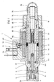
- the pressure relief valve 1 has a valve housing 2, in which a valve cone 4 is guided axially displaceable.
- a seat body 6 is inserted through which an axial port A and a valve seat 8 are formed.
- This seat body 6 can be used for example by press fitting into the housing.
- a radial outlet or tank connection T is formed by an oblique bore star 9.
- the actuation of the valve cone 4 by means of a proportional solenoid 10 which is attached axially to the valve housing 2.
- the proportional magnet 10 has an integrally formed with the valve housing 2 pole tube 12, in which an armature 14 is mounted. At this the valve cone 8 is supported.
- the armature 14 is by means of a control spring 16 in the closing direction of the valve cone eighth biased.
- the bias of the control spring 16 can be changed by means of an adjusting device 18.
- the proportional magnet 10 further has a pole tube 12 encompassing coil housing 20 in which a magnetic coil 22 is received.
- the power supply of the proportional magnet 10 via in Fig. 1 overhead terminals 24, which are combined in a connector body and placed on the coil housing 20.
- the pressure limiting valve 1 designed as a screw-in valve is provided with a connection protection cap 26 placed on the valve housing 2 and a protective cap 28 placed on a lock nut 76 of the adjustment device.
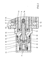
- valve housing Details of the valve housing will be explained below with reference to the enlarged view of Figure 2.
- the seat body 6 has an approximately cup-shaped structure, wherein in a bottom 30 of the valve seat 8 is formed.
- the port A is formed by an axial bore 32 of the seat body 6, which opens into the valve seat 8.
- the outer end face of the bottom 30 is bounded by a receiving bore 34 of the valve housing 2, a tank space 36 in which the extending to the outer peripheral surface of the valve body 2 Schrägbohrungsstern 9 (terminal T) opens.
- the remote from the seat body 6 end face of the receiving bore 34 is formed by a housing web 38 which is penetrated by a coaxial with the receiving bore 34 extending guide bore 40.
- the pole tube 12 is attached to the valve housing 2.
- This can - as in the described embodiment - be designed in one piece with the valve housing 2 or as a separate attached component.
- the armature 14 is guided with its outer circumference in an anchor hole 42 of the pole tube 12.
- the inner circumferential wall of the anchor bore 42 is lined with a foil 44, for example of Teflon material.
- This film 44 forms a sliding bearing for the armature 14, so that it is easily displaceable within the pole tube 12. In order to prevent jamming of the armature 14, this is performed with a certain play, which may be, for example, 1/10 mm.
- the armature 14 divides the receiving space of the pole tube 12 (see also FIG. 1) into a valve cone-side armature space 46 and a rear armature space 48. These two armatures 46, 48 are connected by means of throttle bores 50, which are axially parallel to the valve axis through the armature 14 in the illustrated embodiment extend through.
- the armature has valve seat side a blind hole 52 which extends from the left in Figure 2 end face of the armature 14 to approximately in the axially central region.
- the bottom of the blind hole 52 is provided with V-shaped mutually arranged inclined surfaces 54 on which a ball 56 is supported.
- the valve cone 4 is supported.
- the valve cone 4 has a dargestellen in the closed position in sections in the seat body 6 dipping cone 58, which is seated with an outer peripheral portion on the valve seat 8.
- the cone 58 is adjoined by a cylindrical guide section 60, which passes through the guide bore 40.
- An immersed in the armature 14 end portion 62 is radially stepped back, wherein the outer diameter of this end portion 62 corresponds approximately to the diameter of the ball 56.
- spheres of a conventional ball bearing are used as a ball. These are characterized by high strength and good wear resistance.
- the contact surface of the end portion 62 to the ball 56 is also provided with inclined abutment surfaces 64.
- inclined surfaces 54 and the inclined bearing surfaces 64 is a centering of the ball 56 with respect to the blind hole 52 and correspondingly a centering of the end portion 62 of the valve cone 4 with respect to the ball 56th
- this game is less than the prescribed game between the end portion 62 and the armature 14.
- the game in the region of the guide portion 60 is selected so that in the pole tube 12 befindliches Pressure medium in the idle state does not escape through the annular gap between the guide portion 60 and the guide bore 40 therethrough and the pole tube, so to speak, idles.
- a centering projection 66 is formed on the rear side of the armature 14, onto which a contact disk is placed and which serves for centering the control spring 16 resting against the contact disk. This dips into the inner bore 68 of a closure piece 70 inserted into the pole tube 12. This is positively connected to the pole tube 12, wherein in the illustrated embodiment, the connection is made by crimping.
- a locking screw 72 is screwed over which the coil housing 20 is pressed axially against a shoulder of the valve housing 2.
- a clamping bolt 74 is screwed, via which the bias of the control spring 16 is adjustable.
- the spring-side end portion of the clamping bolt 74 is also provided with a centering pin 66 for the control spring.
- a lock nut 76 is screwed, which is brought to fix the position of the clamping bolt 74 in abutment with the adjacent end face of the closure piece 70.
- the protective cap 28 is placed on the lock nut 76.
- sealing elements are provided on the outer circumference of the closure piece 70 and on the outer circumference of the clamping bolt.
- the pole tube 12 is further divided by a ring 78 of non-magnetic material.
- the above-described construction is characterized by a very simple structural design with small dead spaces, so that when filling the pole tube 12, the formation of air pockets (air pockets) is avoided.
- the seat body 6 is pressed into the valve housing 2. Before this Einspressvorgang the poppet 4 is already in its illustrated position. Due to the comparatively small radial play between the guide section 60 of the valve cone 4 and the bore 40, the conical tip threads securely into the seat body 6. The compensation of tolerances between the position of the armature and the position of the seat body is due to the radial clearance between the valve cone 4 and the armature 14 by a slight tilting of the valve cone.
- the pole tube 12 In its basic position, the pole tube 12 is completely filled with pressure medium. If the proportional magnet 10 is now energized, the armature is displaced to the right by the resulting magnetic forces against the force of the control spring 16 and the valve cone 4 is lifted off the valve seat 8 by the pressure acting on the connection A. The armature 14 and the poppet 4 are in response to the force of the control spring 16, the force applied by the proportional magnet 10 magnetic force and the acting compressive forces in a control position, wherein pressure medium from port A via the controlled depending on the armature travel 14 throttle gap in the Pressure chamber 36 and from there via the oblique hole star 9 to the tank port T can flow out.
- the armature 14 When Stromlosschalt the solenoid valve, the armature 14 is moved by the force of the control spring 16 back to the left, wherein pressure medium from the armature chamber 46 is displaced via the throttle holes 50 in the rear armature chamber 48 - the poppet is then moved back accordingly to the left until it the valve seat 8 is seated, wherein pressure medium is sucked through the above-described annular gap.
- the pressure relief valve 1 is "normally closed” executed.
- the pressure relief valve could also be “normally open” executed, d. h.,
- the valve cone 4 would be biased in the basic position in the opening direction.
- a proportionally adjustable pressure limiting valve in which a valve cone by means of an armature of a proportional solenoid is actuated.
- the valve cone is gimbal-supported in the armature.
- An additional guidance of the valve cone via a housing-side guide, wherein the clearance between the valve cone and the housing-side guide is designed to be less than the clearance between the valve cone and the armature.
Landscapes
- Engineering & Computer Science (AREA)
- Physics & Mathematics (AREA)
- General Engineering & Computer Science (AREA)
- Fluid Mechanics (AREA)
- Mechanical Engineering (AREA)
- General Physics & Mathematics (AREA)
- Automation & Control Theory (AREA)
- Magnetically Actuated Valves (AREA)
- Control Of Fluid Pressure (AREA)
- Fluid-Pressure Circuits (AREA)
- Servomotors (AREA)
- Safety Valves (AREA)
Claims (11)
- Soupape de limitation de pression commandée directement et réglable de façon proportionnelle comportant un siège de soupape (8) formé dans un boîtier de soupape (2), et un cône de soupape (4), qui limitent, lorsque le cône de soupape (4) est dans une position de réglage, une fente d'étranglement, par l'intermédiaire de laquelle un raccord d'entrée (A) est relié à un raccord de sortie (T), le cône de soupape (4) prenant appui avec un jeu radial dans une armature disposée en saillie (14) d'un aimant à action proportionnelle (10), caractérisée par un soutien axial centré à la Cardan du cône de soupape (8) sur l'armature (14) et par un système de guidage (40), solidaire du boîtier et disposé axialement entre le siège de soupape (8) et l'armature (14), pour le cône de soupape (4), cet élément de guidage étant réalisé avec un jeu plus faible que le jeu radial côté armature.
- Soupape de limitation de pression selon la revendication 1, dans laquelle le soutien axial dans l'armature (14) s'effectue par l'intermédiaire d'une bille (56) de préférence insérée à force.
- Soupape de limitation de pression selon la revendication 1 ou 2, dans laquelle le soutien axial s'effectue dans une zone médiane, vue dans la direction axiale, de l'armature (14).
- Soupape de limitation de pression selon la revendication 3, dans laquelle l'armature (14) possède un perçage borgne (52), qui s'étend dans la partie médiane et sur le fond (54) duquel prend appui directement le cône de soupape (4).
- Soupape de limitation de pression selon la revendication 4, dans laquelle le fond (54) est pourvu de surfaces obliques (54).
- Soupape de limitation de pression selon l'une des revendications précédentes, dans laquelle un perçage borgne (52) est étagé à l'intérieur de l'armature (14), dans laquelle pénètre le cône de soupape (4), et dans laquelle la bille (56) est insérée à force dans la partie rétrécie du perçage borgne (52), tandis que l'autre partie du perçage borgne (52) reçoit une section (60) du cône de soupape (4), qui s'étend avec un diamètre constant à travers l'élément de guidage (40) solidaire du boîtier, à partir de l'armature (14).
- Soupape de limitation de pression selon l'une des revendications 2 à 6, dans laquelle le cône de soupape (4) possède, sur son côté arrière, un évidement frontal centré comportant des surfaces obliques (64), qui peuvent venir s'appliquer contre la bille (56).
- Soupape de limitation de pression selon l'une des revendications précédentes, dans laquelle l'armature (14) est traversée par au moins un perçage d'étranglement (50), au moyen duquel un espace (46) de l'armature, situé du côté du cône de soupape, est relié à un espace (48) de l'armature, situé côté arrière.
- Soupape de limitation de pression selon l'une des revendications précédentes, dans laquelle l'armature (14) est supportée par une feuille (44) de manière à glisser le long de sa périphérie extérieure.
- Soupape de limitation de pression selon l'une des revendications précédentes, dans laquelle le cône de soupape (4) est logé à l'état flottant dans l'armature (14).
- Soupape de limitation de pression selon l'une des revendications précédentes, dans laquelle l'armature (14) possède, sur son côté arrière, un téton de centrage (66) pour un ressort de réglage (16).
Applications Claiming Priority (3)
| Application Number | Priority Date | Filing Date | Title |
|---|---|---|---|
| DE10255740 | 2002-11-28 | ||
| DE10255740A DE10255740A1 (de) | 2002-11-28 | 2002-11-28 | Direktgesteuertes prop. Druckbegrenzungsventil |
| PCT/DE2003/003740 WO2004048831A1 (fr) | 2002-11-28 | 2003-11-12 | Soupape de limitation de pression a regulation proportionnelle directe |
Publications (2)
| Publication Number | Publication Date |
|---|---|
| EP1565680A1 EP1565680A1 (fr) | 2005-08-24 |
| EP1565680B1 true EP1565680B1 (fr) | 2006-04-12 |
Family
ID=32308831
Family Applications (1)
| Application Number | Title | Priority Date | Filing Date |
|---|---|---|---|
| EP03779685A Expired - Lifetime EP1565680B1 (fr) | 2002-11-28 | 2003-11-12 | Soupape de limitation de pression a regulation proportionnelle directe |
Country Status (8)
| Country | Link |
|---|---|
| US (1) | US7036788B1 (fr) |
| EP (1) | EP1565680B1 (fr) |
| JP (1) | JP4654036B2 (fr) |
| CN (1) | CN100540964C (fr) |
| AT (1) | ATE323255T1 (fr) |
| AU (1) | AU2003287859A1 (fr) |
| DE (2) | DE10255740A1 (fr) |
| WO (1) | WO2004048831A1 (fr) |
Cited By (1)
| Publication number | Priority date | Publication date | Assignee | Title |
|---|---|---|---|---|
| DE102015222745A1 (de) | 2015-11-18 | 2017-05-18 | Robert Bosch Gmbh | Ventil mit Stromregel- und Druckbegrenzungsfunktion |
Families Citing this family (22)
| Publication number | Priority date | Publication date | Assignee | Title |
|---|---|---|---|---|
| DE102006029267B4 (de) | 2006-06-26 | 2009-07-30 | Thomas Magnete Gmbh | Regelventil für R 744-Klimasysteme |
| DE102006036615B4 (de) * | 2006-08-04 | 2008-07-24 | Rausch & Pausch Gmbh | Steuerbares Magnetventil |
| DE102006054941B3 (de) * | 2006-11-22 | 2008-05-21 | Thomas Magnete Gmbh | Elektromagnet |
| DE102006055796A1 (de) * | 2006-11-27 | 2008-05-29 | Robert Bosch Gmbh | Druckregelventil |
| DE102007031981B4 (de) | 2007-07-10 | 2023-01-12 | Robert Bosch Gmbh | Magnetventil |
| DE102007042207A1 (de) * | 2007-09-05 | 2009-03-12 | Zf Friedrichshafen Ag | Druckbegrenzungsventil und Anordnung eines Druckbegrenzungsventils zur Vorsteuerung eines Druckregelventils |
| US8322376B2 (en) * | 2008-06-09 | 2012-12-04 | Bendix Commercial Vehicle Systems, Llc | Solenoid valve |
| WO2010049166A1 (fr) * | 2008-10-31 | 2010-05-06 | Robert Bosch Gmbh | Electro-aimant |
| JP5307517B2 (ja) * | 2008-11-14 | 2013-10-02 | カヤバ工業株式会社 | ソレノイド |
| EP2494244B1 (fr) * | 2009-10-26 | 2013-09-11 | Hydac Fluidtechnik GmbH | Électrovanne |
| DE102011076784B4 (de) * | 2011-05-31 | 2015-07-30 | Continental Automotive Gmbh | Einlassventil für eine Fluidpumpe und Montageverfahren für ein Einlassventil für eine Fluidpumpe |
| JP5641031B2 (ja) * | 2012-01-16 | 2014-12-17 | 株式会社デンソー | 電磁アクチュエータ |
| DE102012218593A1 (de) | 2012-10-12 | 2014-04-17 | Continental Automotive Gmbh | Ventil für eine Pumpe |
| JP2014105757A (ja) * | 2012-11-27 | 2014-06-09 | Denso Corp | 高圧流体用電磁弁装置 |
| DE102015118090A1 (de) * | 2015-10-23 | 2017-04-27 | Kendrion (Villingen) Gmbh | Elektromagnetisches Ventil |
| CN106167014A (zh) * | 2016-06-29 | 2016-11-30 | 浙江科力车辆控制系统有限公司 | 一种气制动阀 |
| CN106640811B (zh) * | 2016-11-24 | 2018-08-24 | 浙江华益精密机械股份有限公司 | 无泄漏压力补偿电比例节流阀 |
| US11313488B2 (en) * | 2017-08-08 | 2022-04-26 | Mando Corporation | Solenoid valve for brake system |
| DE102017214506A1 (de) * | 2017-08-21 | 2019-02-21 | Robert Bosch Gmbh | Proportionalventil zum Steuern eines gasförmigen Mediums |
| DE102018219429A1 (de) | 2018-11-14 | 2020-05-14 | Robert Bosch Gmbh | Elektromagnet und hydraulisches Ventil mit einem Elektromagnet |
| JP2022057491A (ja) * | 2020-09-30 | 2022-04-11 | 日本電産トーソク株式会社 | 電磁弁 |
| DE202022100569U1 (de) | 2021-02-09 | 2022-02-16 | ECO Holding 1 GmbH | Elektromagnetisches Hydraulikventil |
Family Cites Families (14)
| Publication number | Priority date | Publication date | Assignee | Title |
|---|---|---|---|---|
| US4027850A (en) * | 1975-09-05 | 1977-06-07 | Peter Paul Electronics Co., Inc. | Solenoid valve |
| JPS5740775U (fr) * | 1980-08-19 | 1982-03-05 | ||
| US5546987A (en) * | 1981-11-06 | 1996-08-20 | Sule; Akos | Solenoid valve |
| DE3244840A1 (de) | 1981-12-17 | 1983-06-30 | Edi System S.r.l., Modena | Normalerweise geschlossenes zweiwege-nadelventil mit elektromagnetischer steuerung |
| JPS6047972U (ja) * | 1983-09-09 | 1985-04-04 | 株式会社トキメック | 比例ソレノイド形電磁圧力制御弁 |
| DE3528296A1 (de) * | 1985-08-07 | 1987-02-19 | Fluidtech Gmbh | Magnetventil |
| FR2632045B3 (fr) * | 1988-05-26 | 1990-10-05 | Joly Luc | Dispositif de commande de fluide a clapet sans frottement, notamment detendeur pour gaz ultra pur |
| JPH02173485A (ja) * | 1988-12-23 | 1990-07-04 | Tokyo Keiki Co Ltd | 比例ソレノイド |
| DE59501830D1 (de) * | 1994-08-30 | 1998-05-14 | Pierburg Ag | Elektromagnetisches Schaltventil |
| US5785298A (en) * | 1996-04-15 | 1998-07-28 | Teknocraft, Inc. | Proportional solenoid-controlled fluid valve assembly |
| DE19625349A1 (de) * | 1996-06-25 | 1998-01-02 | Rexroth Mannesmann Gmbh | Magnetbetätigtes Sitzventil |
| DE19917756A1 (de) * | 1998-07-06 | 2000-01-13 | Continental Teves Ag & Co Ohg | Elektromagnetventil |
| DE19907732B4 (de) | 1999-02-23 | 2008-08-28 | Bosch Rexroth Aktiengesellschaft | Hydraulisches Magnetventil |
| DE10040763A1 (de) * | 2000-08-19 | 2002-02-28 | Bosch Gmbh Robert | Elektromagnetisch betätigtes Ventil, insbesondere für hydraulische Bremsanlagen in Kraftfahrzeugen |
-
2002
- 2002-11-28 DE DE10255740A patent/DE10255740A1/de not_active Withdrawn
-
2003
- 2003-11-12 CN CNB2003801041140A patent/CN100540964C/zh not_active Expired - Fee Related
- 2003-11-12 US US10/534,727 patent/US7036788B1/en not_active Expired - Lifetime
- 2003-11-12 AT AT03779685T patent/ATE323255T1/de not_active IP Right Cessation
- 2003-11-12 AU AU2003287859A patent/AU2003287859A1/en not_active Abandoned
- 2003-11-12 WO PCT/DE2003/003740 patent/WO2004048831A1/fr active IP Right Grant
- 2003-11-12 EP EP03779685A patent/EP1565680B1/fr not_active Expired - Lifetime
- 2003-11-12 DE DE50302986T patent/DE50302986D1/de not_active Expired - Lifetime
- 2003-11-12 JP JP2004554199A patent/JP4654036B2/ja not_active Expired - Fee Related
Cited By (2)
| Publication number | Priority date | Publication date | Assignee | Title |
|---|---|---|---|---|
| DE102015222745A1 (de) | 2015-11-18 | 2017-05-18 | Robert Bosch Gmbh | Ventil mit Stromregel- und Druckbegrenzungsfunktion |
| US10564652B2 (en) | 2015-11-18 | 2020-02-18 | Robert Bosch Gmbh | Valve with flow control and pressure limitation function |
Also Published As
| Publication number | Publication date |
|---|---|
| JP4654036B2 (ja) | 2011-03-16 |
| CN1717559A (zh) | 2006-01-04 |
| JP2006508305A (ja) | 2006-03-09 |
| DE10255740A1 (de) | 2004-06-09 |
| AU2003287859A1 (en) | 2004-06-18 |
| DE50302986D1 (de) | 2006-05-24 |
| ATE323255T1 (de) | 2006-04-15 |
| WO2004048831A1 (fr) | 2004-06-10 |
| CN100540964C (zh) | 2009-09-16 |
| EP1565680A1 (fr) | 2005-08-24 |
| US7036788B1 (en) | 2006-05-02 |
Similar Documents
| Publication | Publication Date | Title |
|---|---|---|
| EP1565680B1 (fr) | Soupape de limitation de pression a regulation proportionnelle directe | |
| DE602004004254T2 (de) | Servoventil zum Steuern eines Einspritzventils einer Brennkraftmaschine | |
| EP1270930B1 (fr) | Vanne electromagnetique pour piloter un injecteur d'un moteur a combustion interne | |
| DE4211913C2 (de) | Magnetbetätigtes Druckregelventil | |
| EP1592593B1 (fr) | Soupape electromagnetique | |
| EP1882122B1 (fr) | Valve, notamment valve proportionnelle de limitation de pression | |
| DE3823430C2 (fr) | ||
| EP0302068A1 (fr) | Soupape de non-retour. | |
| DE102017214506A1 (de) | Proportionalventil zum Steuern eines gasförmigen Mediums | |
| DE102007025614A1 (de) | Ankerhubeinstellung für Magnetventil | |
| DE3925794A1 (de) | Elektromagnetventil | |
| DE2052307A1 (de) | Elektromagnetisch betätigtes Sitzventil | |
| EP3189289B1 (fr) | Détendeur à commande électromagnétique | |
| DE2506928B2 (de) | Gebirgsschlagventil für hydraulische Grubenstempel | |
| WO2008000370A1 (fr) | Soupape de régulation pour des systèmes de climatisation r 744 | |
| EP0549628B1 (fr) | Dispositif de commande pour un verin hydraulique | |
| DE10014191B4 (de) | Steuerventil | |
| WO2017080707A1 (fr) | Soupape d'aspiration à commande électromagnétique pour pompe à haute pression et pompe à haute pression | |
| DE102013200634B4 (de) | Druckregelventil für einen Kraftstoff-Hochdruckspeicher | |
| DE19625349A1 (de) | Magnetbetätigtes Sitzventil | |
| DE4211551C2 (de) | Verstellpumpe mit einem Druckbegrenzungs- und einem Druckzuschaltventil | |
| EP1317638B1 (fr) | Soupape de distribution | |
| DE102009041591B4 (de) | Magnetventil | |
| DE19936943A1 (de) | Brennstoffeinspritzventil | |
| EP3359851A1 (fr) | Électrovanne de commande |
Legal Events
| Date | Code | Title | Description |
|---|---|---|---|
| PUAI | Public reference made under article 153(3) epc to a published international application that has entered the european phase |
Free format text: ORIGINAL CODE: 0009012 |
|
| 17P | Request for examination filed |
Effective date: 20050512 |
|
| AK | Designated contracting states |
Kind code of ref document: A1 Designated state(s): AT BE BG CH CY CZ DE DK EE ES FI FR GB GR HU IE IT LI LU MC NL PT RO SE SI SK TR |
|
| AX | Request for extension of the european patent |
Extension state: AL LT LV MK |
|
| GRAP | Despatch of communication of intention to grant a patent |
Free format text: ORIGINAL CODE: EPIDOSNIGR1 |
|
| GRAS | Grant fee paid |
Free format text: ORIGINAL CODE: EPIDOSNIGR3 |
|
| GRAA | (expected) grant |
Free format text: ORIGINAL CODE: 0009210 |
|
| DAX | Request for extension of the european patent (deleted) | ||
| AK | Designated contracting states |
Kind code of ref document: B1 Designated state(s): AT BE BG CH CY CZ DE DK EE ES FI FR GB GR HU IE IT LI LU MC NL PT RO SE SI SK TR |
|
| PG25 | Lapsed in a contracting state [announced via postgrant information from national office to epo] |
Ref country code: SI Free format text: LAPSE BECAUSE OF FAILURE TO SUBMIT A TRANSLATION OF THE DESCRIPTION OR TO PAY THE FEE WITHIN THE PRESCRIBED TIME-LIMIT Effective date: 20060412 Ref country code: IE Free format text: LAPSE BECAUSE OF FAILURE TO SUBMIT A TRANSLATION OF THE DESCRIPTION OR TO PAY THE FEE WITHIN THE PRESCRIBED TIME-LIMIT Effective date: 20060412 Ref country code: IT Free format text: LAPSE BECAUSE OF FAILURE TO SUBMIT A TRANSLATION OF THE DESCRIPTION OR TO PAY THE FEE WITHIN THE PRESCRIBED TIME-LIMIT;WARNING: LAPSES OF ITALIAN PATENTS WITH EFFECTIVE DATE BEFORE 2007 MAY HAVE OCCURRED AT ANY TIME BEFORE 2007. THE CORRECT EFFECTIVE DATE MAY BE DIFFERENT FROM THE ONE RECORDED. Effective date: 20060412 Ref country code: RO Free format text: LAPSE BECAUSE OF FAILURE TO SUBMIT A TRANSLATION OF THE DESCRIPTION OR TO PAY THE FEE WITHIN THE PRESCRIBED TIME-LIMIT Effective date: 20060412 Ref country code: SK Free format text: LAPSE BECAUSE OF FAILURE TO SUBMIT A TRANSLATION OF THE DESCRIPTION OR TO PAY THE FEE WITHIN THE PRESCRIBED TIME-LIMIT Effective date: 20060412 Ref country code: CZ Free format text: LAPSE BECAUSE OF FAILURE TO SUBMIT A TRANSLATION OF THE DESCRIPTION OR TO PAY THE FEE WITHIN THE PRESCRIBED TIME-LIMIT Effective date: 20060412 Ref country code: NL Free format text: LAPSE BECAUSE OF FAILURE TO SUBMIT A TRANSLATION OF THE DESCRIPTION OR TO PAY THE FEE WITHIN THE PRESCRIBED TIME-LIMIT Effective date: 20060412 Ref country code: FI Free format text: LAPSE BECAUSE OF FAILURE TO SUBMIT A TRANSLATION OF THE DESCRIPTION OR TO PAY THE FEE WITHIN THE PRESCRIBED TIME-LIMIT Effective date: 20060412 |
|
| REG | Reference to a national code |
Ref country code: GB Ref legal event code: FG4D Free format text: NOT ENGLISH |
|
| REG | Reference to a national code |
Ref country code: CH Ref legal event code: EP |
|
| REF | Corresponds to: |
Ref document number: 50302986 Country of ref document: DE Date of ref document: 20060524 Kind code of ref document: P |
|
| REG | Reference to a national code |
Ref country code: IE Ref legal event code: FG4D Free format text: LANGUAGE OF EP DOCUMENT: GERMAN |
|
| PG25 | Lapsed in a contracting state [announced via postgrant information from national office to epo] |
Ref country code: SE Free format text: LAPSE BECAUSE OF FAILURE TO SUBMIT A TRANSLATION OF THE DESCRIPTION OR TO PAY THE FEE WITHIN THE PRESCRIBED TIME-LIMIT Effective date: 20060712 Ref country code: DK Free format text: LAPSE BECAUSE OF FAILURE TO SUBMIT A TRANSLATION OF THE DESCRIPTION OR TO PAY THE FEE WITHIN THE PRESCRIBED TIME-LIMIT Effective date: 20060712 |
|
| PG25 | Lapsed in a contracting state [announced via postgrant information from national office to epo] |
Ref country code: ES Free format text: LAPSE BECAUSE OF FAILURE TO SUBMIT A TRANSLATION OF THE DESCRIPTION OR TO PAY THE FEE WITHIN THE PRESCRIBED TIME-LIMIT Effective date: 20060723 |
|
| GBT | Gb: translation of ep patent filed (gb section 77(6)(a)/1977) | ||
| PG25 | Lapsed in a contracting state [announced via postgrant information from national office to epo] |
Ref country code: PT Free format text: LAPSE BECAUSE OF FAILURE TO SUBMIT A TRANSLATION OF THE DESCRIPTION OR TO PAY THE FEE WITHIN THE PRESCRIBED TIME-LIMIT Effective date: 20060912 |
|
| NLV1 | Nl: lapsed or annulled due to failure to fulfill the requirements of art. 29p and 29m of the patents act | ||
| REG | Reference to a national code |
Ref country code: IE Ref legal event code: FD4D |
|
| PG25 | Lapsed in a contracting state [announced via postgrant information from national office to epo] |
Ref country code: MC Free format text: LAPSE BECAUSE OF NON-PAYMENT OF DUE FEES Effective date: 20061130 Ref country code: BE Free format text: LAPSE BECAUSE OF NON-PAYMENT OF DUE FEES Effective date: 20061130 |
|
| PLBE | No opposition filed within time limit |
Free format text: ORIGINAL CODE: 0009261 |
|
| STAA | Information on the status of an ep patent application or granted ep patent |
Free format text: STATUS: NO OPPOSITION FILED WITHIN TIME LIMIT |
|
| 26N | No opposition filed |
Effective date: 20070115 |
|
| EN | Fr: translation not filed | ||
| BERE | Be: lapsed |
Owner name: BOSCH REXROTH A.G. Effective date: 20061130 |
|
| PG25 | Lapsed in a contracting state [announced via postgrant information from national office to epo] |
Ref country code: AT Free format text: LAPSE BECAUSE OF NON-PAYMENT OF DUE FEES Effective date: 20061112 |
|
| PG25 | Lapsed in a contracting state [announced via postgrant information from national office to epo] |
Ref country code: GR Free format text: LAPSE BECAUSE OF FAILURE TO SUBMIT A TRANSLATION OF THE DESCRIPTION OR TO PAY THE FEE WITHIN THE PRESCRIBED TIME-LIMIT Effective date: 20060713 Ref country code: FR Free format text: LAPSE BECAUSE OF FAILURE TO SUBMIT A TRANSLATION OF THE DESCRIPTION OR TO PAY THE FEE WITHIN THE PRESCRIBED TIME-LIMIT Effective date: 20070309 |
|
| PG25 | Lapsed in a contracting state [announced via postgrant information from national office to epo] |
Ref country code: EE Free format text: LAPSE BECAUSE OF FAILURE TO SUBMIT A TRANSLATION OF THE DESCRIPTION OR TO PAY THE FEE WITHIN THE PRESCRIBED TIME-LIMIT Effective date: 20060412 Ref country code: BG Free format text: LAPSE BECAUSE OF FAILURE TO SUBMIT A TRANSLATION OF THE DESCRIPTION OR TO PAY THE FEE WITHIN THE PRESCRIBED TIME-LIMIT Effective date: 20060712 |
|
| PG25 | Lapsed in a contracting state [announced via postgrant information from national office to epo] |
Ref country code: HU Free format text: LAPSE BECAUSE OF FAILURE TO SUBMIT A TRANSLATION OF THE DESCRIPTION OR TO PAY THE FEE WITHIN THE PRESCRIBED TIME-LIMIT Effective date: 20061013 Ref country code: TR Free format text: LAPSE BECAUSE OF FAILURE TO SUBMIT A TRANSLATION OF THE DESCRIPTION OR TO PAY THE FEE WITHIN THE PRESCRIBED TIME-LIMIT Effective date: 20060412 Ref country code: CH Free format text: LAPSE BECAUSE OF NON-PAYMENT OF DUE FEES Effective date: 20071130 Ref country code: LI Free format text: LAPSE BECAUSE OF NON-PAYMENT OF DUE FEES Effective date: 20071130 Ref country code: LU Free format text: LAPSE BECAUSE OF NON-PAYMENT OF DUE FEES Effective date: 20061112 |
|
| REG | Reference to a national code |
Ref country code: CH Ref legal event code: PL |
|
| PG25 | Lapsed in a contracting state [announced via postgrant information from national office to epo] |
Ref country code: FR Free format text: LAPSE BECAUSE OF FAILURE TO SUBMIT A TRANSLATION OF THE DESCRIPTION OR TO PAY THE FEE WITHIN THE PRESCRIBED TIME-LIMIT Effective date: 20060412 Ref country code: CY Free format text: LAPSE BECAUSE OF FAILURE TO SUBMIT A TRANSLATION OF THE DESCRIPTION OR TO PAY THE FEE WITHIN THE PRESCRIBED TIME-LIMIT Effective date: 20060412 |
|
| PGFP | Annual fee paid to national office [announced via postgrant information from national office to epo] |
Ref country code: DE Payment date: 20210126 Year of fee payment: 18 |
|
| PGFP | Annual fee paid to national office [announced via postgrant information from national office to epo] |
Ref country code: GB Payment date: 20211123 Year of fee payment: 19 |
|
| PGFP | Annual fee paid to national office [announced via postgrant information from national office to epo] |
Ref country code: IT Payment date: 20211130 Year of fee payment: 19 |
|
| REG | Reference to a national code |
Ref country code: DE Ref legal event code: R119 Ref document number: 50302986 Country of ref document: DE |
|
| PG25 | Lapsed in a contracting state [announced via postgrant information from national office to epo] |
Ref country code: DE Free format text: LAPSE BECAUSE OF NON-PAYMENT OF DUE FEES Effective date: 20220601 |
|
| GBPC | Gb: european patent ceased through non-payment of renewal fee |
Effective date: 20221112 |
|
| PG25 | Lapsed in a contracting state [announced via postgrant information from national office to epo] |
Ref country code: IT Free format text: LAPSE BECAUSE OF NON-PAYMENT OF DUE FEES Effective date: 20221112 Ref country code: GB Free format text: LAPSE BECAUSE OF NON-PAYMENT OF DUE FEES Effective date: 20221112 |