EP1565652B1 - Anschlussblock für eine hydrostatische kolbenmaschine - Google Patents
Anschlussblock für eine hydrostatische kolbenmaschine Download PDFInfo
- Publication number
- EP1565652B1 EP1565652B1 EP04790264A EP04790264A EP1565652B1 EP 1565652 B1 EP1565652 B1 EP 1565652B1 EP 04790264 A EP04790264 A EP 04790264A EP 04790264 A EP04790264 A EP 04790264A EP 1565652 B1 EP1565652 B1 EP 1565652B1
- Authority
- EP
- European Patent Office
- Prior art keywords
- connection block
- working
- pressure
- pressure duct
- working pressure
- Prior art date
- Legal status (The legal status is an assumption and is not a legal conclusion. Google has not performed a legal analysis and makes no representation as to the accuracy of the status listed.)
- Expired - Lifetime
Links
- 230000002706 hydrostatic effect Effects 0.000 title claims abstract description 25
- 210000003734 kidney Anatomy 0.000 claims description 15
- 230000006835 compression Effects 0.000 description 6
- 238000007906 compression Methods 0.000 description 6
- 238000010586 diagram Methods 0.000 description 3
- 238000012423 maintenance Methods 0.000 description 3
- 238000005266 casting Methods 0.000 description 2
- 230000001419 dependent effect Effects 0.000 description 2
- 239000012530 fluid Substances 0.000 description 2
- 230000010354 integration Effects 0.000 description 2
- 238000003754 machining Methods 0.000 description 2
- 238000007789 sealing Methods 0.000 description 2
- 238000010276 construction Methods 0.000 description 1
- 230000008878 coupling Effects 0.000 description 1
- 238000010168 coupling process Methods 0.000 description 1
- 238000005859 coupling reaction Methods 0.000 description 1
- 238000011161 development Methods 0.000 description 1
- 230000018109 developmental process Effects 0.000 description 1
- 238000007599 discharging Methods 0.000 description 1
- 238000005553 drilling Methods 0.000 description 1
- 230000002349 favourable effect Effects 0.000 description 1
- 238000001914 filtration Methods 0.000 description 1
- 239000012535 impurity Substances 0.000 description 1
- 238000005461 lubrication Methods 0.000 description 1
- 238000003801 milling Methods 0.000 description 1
- 230000007935 neutral effect Effects 0.000 description 1
- 230000000149 penetrating effect Effects 0.000 description 1
- 230000001105 regulatory effect Effects 0.000 description 1
Images


Classifications
-
- F—MECHANICAL ENGINEERING; LIGHTING; HEATING; WEAPONS; BLASTING
- F04—POSITIVE - DISPLACEMENT MACHINES FOR LIQUIDS; PUMPS FOR LIQUIDS OR ELASTIC FLUIDS
- F04B—POSITIVE-DISPLACEMENT MACHINES FOR LIQUIDS; PUMPS
- F04B23/00—Pumping installations or systems
- F04B23/04—Combinations of two or more pumps
- F04B23/06—Combinations of two or more pumps the pumps being all of reciprocating positive-displacement type
-
- F—MECHANICAL ENGINEERING; LIGHTING; HEATING; WEAPONS; BLASTING
- F04—POSITIVE - DISPLACEMENT MACHINES FOR LIQUIDS; PUMPS FOR LIQUIDS OR ELASTIC FLUIDS
- F04B—POSITIVE-DISPLACEMENT MACHINES FOR LIQUIDS; PUMPS
- F04B1/00—Multi-cylinder machines or pumps characterised by number or arrangement of cylinders
- F04B1/12—Multi-cylinder machines or pumps characterised by number or arrangement of cylinders having cylinder axes coaxial with, or parallel or inclined to, main shaft axis
- F04B1/20—Multi-cylinder machines or pumps characterised by number or arrangement of cylinders having cylinder axes coaxial with, or parallel or inclined to, main shaft axis having rotary cylinder block
- F04B1/2014—Details or component parts
- F04B1/2064—Housings
-
- F—MECHANICAL ENGINEERING; LIGHTING; HEATING; WEAPONS; BLASTING
- F04—POSITIVE - DISPLACEMENT MACHINES FOR LIQUIDS; PUMPS FOR LIQUIDS OR ELASTIC FLUIDS
- F04B—POSITIVE-DISPLACEMENT MACHINES FOR LIQUIDS; PUMPS
- F04B1/00—Multi-cylinder machines or pumps characterised by number or arrangement of cylinders
- F04B1/12—Multi-cylinder machines or pumps characterised by number or arrangement of cylinders having cylinder axes coaxial with, or parallel or inclined to, main shaft axis
- F04B1/20—Multi-cylinder machines or pumps characterised by number or arrangement of cylinders having cylinder axes coaxial with, or parallel or inclined to, main shaft axis having rotary cylinder block
- F04B1/22—Multi-cylinder machines or pumps characterised by number or arrangement of cylinders having cylinder axes coaxial with, or parallel or inclined to, main shaft axis having rotary cylinder block having two or more sets of cylinders or pistons
Definitions
- the invention relates to a connection block for a hydrostatic piston machine, which is provided for simultaneous operation in a first and in a second hydraulic circuit.
- An axial piston machine which is suitable for operation in a first and in a second hydraulic circuit is known from DE 34 13 867 A1 known.
- a connection block is provided in which working pressure channels are arranged.
- the working pressure channels open at the end face of the connection block to a control plate out, are formed in the control kidneys. Cylinder spaces of a rotatably mounted cylinder drum are temporarily connected to the working lines during rotation of the cylinder drum via the control elements.
- the US 2002/0157391 A1 shows a hydrostatic piston engine with a terminal block according to the preamble of claim 1.
- the piston engine is suitable for operation in two circuits.
- a first and a second working pressure channel are formed, via which a first or second working line of the hydraulic circuit can be connected to a first or second control kidney of a control plate.
- a third and a fourth working pressure channel is formed, via which a third or fourth working line of the hydraulic circuit can be connected to a third or fourth control kidney of a control plate.
- connection block for a hydrostatic piston engine which allows a compact hydraulic system.
- a feed pressure channel is additionally formed in the connection block.
- This feed pressure channel can be connected via a separate feed device with a working pressure channel.
- the connection block is a compact unit, which is installed together with the hydrostatic piston engine in a hydraulic system, without an additional supply of the feed pressure outside of the hydrostatic piston machine and the connection block is made to the working lines.
- connection block it is advantageous to also integrate the feed devices into the connection block.
- recesses are formed in the connection block into which the feed devices can be inserted.
- the feeders are designed for this purpose as a compact unit with the valves required for the supply, which can be screwed together as an assembly, the so-called cartridge, in the corresponding recess in the terminal block.
- each feed device with a high pressure relief valve.
- each working pressure channel is assigned its own high-pressure relief valve. Relief can take place when a pressure limit in a single working line is exceeded, separated from the other working lines or the associated working pressure channels. Both the infeed and the high pressure limitation are thus integrated in the connection block.
- connection block it is advantageous, at least for a hydraulic circuit, to arrange the two working pressure channels in the connection block such that the two connections are located on one side of the connection block. On another side of the terminal block so that the arrangement of all dining facilities is possible.
- the proximity of the common arrangement of the feed devices in turn leads to a favorable, approximately symmetrical geometry of the feed pressure channel. Further integration is achieved by placing an auxiliary pump in the terminal block.
- the auxiliary pump is arranged in a recess of the connection block, wherein the auxiliary pump is preferably designed as a sickle pump whose high-pressure kidney is connected within the connection block with the feed pressure channel.
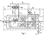
- the hydrostatic piston machine 1 comprises a pump 2 for the parallel conveying of pressure medium into two separate, closed hydraulic circuits.
- the delivery rate of the pump 2 can be changed together by an adjusting device 3 for both hydraulic circuits.
- the adjusting device 3 consists of a cylinder and a control piston 4 arranged therein, which is acted upon in a known manner at opposite mutually oriented piston surfaces in each case a control pressure chamber with a control pressure.
- the two control pressure chambers are connected via a respective control pressure line 6a, 6b with a control pressure control valve 5.
- the first hydraulic circuit is formed from a first working line 7 and a second working line 8.
- the pump 2 promotes either in the first working line 7 or in the second working line 8.
- a promotion in the first working line 7 takes place simultaneously due to the common adjustment of a promotion of pressure medium in a third working line 7 'of the second hydraulic circuit or, in promotion in the second working line 8 of the first hydraulic circuit, in a fourth working line 8 'of the second hydraulic circuit.
- the first hydraulic circuit consisting of the first working line 7 and the second working line 8 is hydraulically independent of the second hydraulic circuit, consisting of its third working line 7 'and its fourth working line 8'.
- the auxiliary pump 9 When starting the pump 2, first the first hydraulic circuit and the second hydraulic circuit is fed by an auxiliary pump 9 with pressure medium.
- the auxiliary pump 9 sucks pressure medium via a suction line 10 from a tank volume 11.
- a filter 12 is arranged in the suction line 10 outside the housing of the hydrostatic piston machine 1, which frees the sucked pressure fluid from impurities.
- a first feed device 13 and a second feed device 14 are provided, wherein the first Feed device 13 is connected to the first working line 7 of the first hydraulic circuit and the second feed device 14 to the second working line 8 of the first hydraulic circuit.
- a third feeder 13 ' is connected to the third working line 7' of the second hydraulic circuit and a fourth feeder 14 'is connected to the fourth working line 8' of the second hydraulic circuit.
- the first to fourth feeders 13, 13 ', 14 and 14' are connected in common with a feed pressure channel 15, in which the auxiliary pump 9 promotes the sucked pressure medium.
- a check valve 17 which, for supplying pressure medium, a flow path from the feed pressure channel 15 in the direction of the respectively connected working line 7, 8, 7 'or 'opens, as long as the pressure in the feed pressure channel 15 is greater than the respective working pressure.
- Parallel to the check valve 17 is a respective high pressure relief valve 18 in the feeders 13, 13 ', 14 and 14' are arranged. When a critical pressure in the respective working line 7, 8, 7 ', or 8' is exceeded, the respective high-pressure relief valve 18 opens in the direction of the feed pressure channel 15.
- the control pressure control valve 5 is designed as a 4/3-way valve, which is continuously adjustable. To set a specific position, the control pressure regulating valve 5 is acted upon by a force acting in the axial direction starting from its neutral position in which it is held by compression springs. This force is generated as a force difference between two proportional magnets 20a and 20b, which act in the same direction with a respective compression spring on a valve piston of the control pressure control valve 5. The respectively adjusted position of the control piston 4 is taken into account in the regulation of the control pressure by a valve sleeve of the control pressure control valve 5 is connected to the actuating piston 4 via a coupling rod 21.
- control pressure control valve 5 is connected to the supply pressure duct 15 via a control pressure supply 16.
- the adjusting device 3 can thus be actuated when starting the pump 2 from the time at which the auxiliary pump 9 has built a pressure in the feed pressure channel 15.
- the adjusting device 3 can thus be operated independently of the funded by the pump 2 in the first hydraulic circuit or second hydraulic circuit pressure medium quantity.
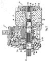
- the auxiliary pump 9 and the pump 2 are driven in the illustrated embodiment by a common drive shaft 22.
- the common drive shaft 22 is supported by a roller bearing 23 at one end of a pump housing 24.
- the common drive shaft 22 is mounted in a sliding bearing 26, which in a Terminal block 25 is arranged, which closes the pump housing 24 at the opposite end.
- the terminal block 25 is a, the terminal block completely penetrating in the axial direction recess 33 is formed, in which on the one hand the sliding bearing 26 is arranged and which is penetrated to the other by the common drive shaft 22.
- the auxiliary pump 9 is inserted into a radial extension of the recess 33.
- the common drive shaft 22 has a toothing 27.1, which is in engagement with the corresponding toothing of the auxiliary pump shaft 28.
- the auxiliary pump shaft 28 is supported in the recess 33 by a first auxiliary pump sliding bearing 34 and by a second auxiliary pump sliding bearing 35 in the auxiliary pump connecting plate 31.
- a gear 29 is arranged, which is in engagement with a ring gear 30.
- the ring gear 30 which is rotatably arranged in the auxiliary pump connection plate 31, also driven by the auxiliary pump shaft 28 and thus ultimately by the common drive shaft 22.
- the suction and the pressure-side connection for the auxiliary pump 9 are formed.
- the auxiliary pump 9 is fixed in the radial extension of the recess 33 of the connection block 25 by a cover 32 which is mounted on the connection block 25.
- connection block 25 In a particularly preferred embodiment of the connection block 25 according to the invention, the suction and the pressure-side connection are formed in the connection block 25, as described below in the detailed description of the connection block 25 according to the invention with reference to FIG Fig. 3 to 8 is explained.
- the inner ring of the roller bearing 23 is fixed in the axial direction on the common drive shaft 22.
- the inner ring rests on the one hand on a collar 36 of the common drive shaft 22 and is held on the other side by a locking ring 37 in this axial position, which is inserted in a groove of the common drive shaft 22.
- the axial position of the roller bearing 23 with respect to the pump housing 24 is determined by a locking ring 38 which is inserted into a circumferential groove of the shaft opening 39.
- a sealing ring 40 and finally a further locking ring 41 is disposed in the shaft opening 39, wherein the locking ring 41 is inserted into a circumferential groove of the shaft opening 39.
- a drive toothing 42 is formed, via which the hydrostatic piston engine is driven by a drive machine, not shown.
- a cylinder drum 43 is arranged, which has a central passage opening 44, which is penetrated by the common drive shaft 22. Via a further drive toothing 45, the cylinder drum 43 is secured against rotation, but slidably connected in the axial direction with the common drive shaft 22, so that a rotational movement of the common drive shaft 22 transmits to the cylinder drum 43.
- a further securing ring 46 is used, on which a first support plate 47 rests.
- the first support disk 47 forms a first spring bearing for a compression spring 48.
- a second spring bearing for the compression spring 48 is formed by a second support plate 49, located on the front side of the other Drive toothing 45 is supported.
- the compression spring 48 thus exerts on the one hand on the common drive shaft 42 and on the other hand on the cylinder drum 43 in each case a force in the opposite axial direction.
- the common drive shaft 22 is loaded so that the outer ring of the roller bearing 23 is supported on the disc 38.
- the compression spring 48 acts on the cylindrical drum 43, which is held with a formed on the end face of the cylindrical drum 43 spherical recess 51 in contact with a control plate 52.
- the control plate 52 in turn bears sealingly against the connection block 25 with the side remote from the cylinder drum 43.
- the cylinder drum 43 is centered.
- the control plate 52 may also be made flat.
- the position of the control plate 52 in the radial direction is determined by the outer circumference of the sliding bearing 26.
- the sliding bearing 26 is used for this purpose only partially in the recess 33 in the terminal block 25.
- cylinder bores 53 are distributed over a common pitch circle introduced, in which piston 54 'are arranged, which are longitudinally displaceable in the cylinder bores 53.
- pistons 54 protrude partially out of the cylinder drum 43.
- a respective sliding shoe 55 is attached to the piston 54, via which the piston 54 is supported on a running surface 56 of a swash plate 57.
- the angle which the running surface 56 of the swashplate 57 encloses with the central axis can be changed.
- the swash plate 57 can be adjusted by the adjusting device 3 in its inclination.
- the swash plate 57 is roller-mounted in the pump housing 24.
- connection block 25 For connecting the hydrostatic piston machine 1 to a first hydraulic circuit and to a second hydraulic circuit, a first connection 58 for a first working power and a second connection 58 'for a second working line are shown schematically in the connection block 25, which in a manner not shown on the Control plate 52 are connected to the cylinder bores 53.
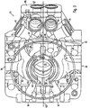
- Fig. 3 shows a perspective view of a terminal block according to the invention 25.
- the terminal block 25 is shown substantially from the side of the control plate 52 from.
- a first working pressure channel 60 and a second working pressure channel 61 are arranged.
- the first working pressure channel 60 and the second working pressure channel 61 are associated with the first hydraulic circuit.
- the second hydraulic circuit, a third working pressure channel 62 and a fourth working pressure channel 63 are assigned.
- the four working pressure channels 60 to 63 connect the suction or pressure-side working lines 7, 7 ', 8 and 8' of the first and second hydraulic circuits to the corresponding control elements of the control plate 52.
- a first connection 64 is formed, to which the first working line 7 of the first hydraulic circuit can be connected.
- a second connection 65 is formed on the end of the second working pressure channel 61 located diametrically opposite the longitudinal axis of the connection block 25.
- a third port 66 and a fourth port 67 are formed on the outside of the port block 25.
- the third terminal 66 and the fourth terminal 67 are disposed on the same side of the terminal block 25.
- the respectively remote from the terminals 64 to 67 ends of the working pressure channels 60 to 63 terminate in a surface of the terminal block 25, at which the control plate 52 is tight.
- the orifices are kidney-shaped.
- the position of the mouths of the first working pressure channel 60 and the second working pressure channel 61 corresponds to the position of a first control kidney and a second control kidney in the control plate 52 and are provided in the drawing by the reference numerals 68 and 69.
- the terminals 64 and 65 are subsequently produced by preferably machining processes to provide sufficient surface quality for sealing engagement with the first and second Ensure work lead 7 and 8.
- the kidney-shaped orifices 68 and 69 are also introduced into the cast blank, e.g. by milling.
- the connections and recesses to be described below, which are located on the outside of the connection block 25, are likewise produced by machining, the channels connected to them each being already produced during the casting of the blank by means of molded parts.
- Control plate 52 further comprises a third control kidney 70 'and a fourth control kidney 71' which extend along a respective portion of another arc of a smaller diameter.
- Corresponding outlets 70 and 71 of the third working pressure channel 62 and the fourth working pressure channel 63 correspond to the position of the third control kidney 70 'and the fourth control kidney 71' in the control plate 52.
- the orifices 68 to 71 of the working pressure channels 60 to 63 are flow-connected to the control kidneys 68 to 71.
- the first working pressure channel 60 is connected via a first connecting channel 72 with a first recess 76.
- the second, third and fourth working pressure ducts 61, 62 and 63 are also connected via a second, third and fourth connecting channel 73, 74 and 75 to a second, third and fourth recess 77, 78 and 79.
- a common feed pressure channel 80 is connected to the first to fourth recesses 76 to 79.
- the first to fourth recesses 76 to 79 are for receiving the in the Fig. 3 Not shown dining facilities 13, 14, 13 'and 14' are provided.
- the feeders 13, 14, 13 'and 14' each include a check valve 17, which opens in the direction of the respective working pressure channel 60 to 63.
- the check valve 17 is open pressure medium flows from the common feed pressure channel 80 in the corresponding working pressure duct 60 to 63, as long as the pressure in the feed pressure channel 80 is higher than in the respective working line 7, 8, 7 'and 8'.
- the pressures in the four working pipes 7, 8, 7 'and 8' can be measured separately via a first to fourth measuring connection.
- a second measuring channel 81 branches off from the second connecting channel 73, which opens a second measuring port 82 on the outer side of the housing.
- the first recess 76 and the second recess 77 provided for receiving the feed devices 13 and 14 of the first hydraulic circuit are arranged in a V-shape and are introduced into the connection block 25 on the side remote from the third connection 66 and the fourth connection 67.
- the third recess 78 and the fourth recess 79 are also arranged in a V-shape with a preferably identical opening angle.
- the third recess 78 and the fourth recess 79 assigned to the second hydraulic circuit are arranged offset in the axial direction with respect to the longitudinal axis to the first recess 76 and the second recess 77. Accordingly, the feed pressure channel 80 extends in the axial direction.
- a crizoventilausnaturalung 83 and a Niederbuchventilausnaturalung 84 are further arranged.
- the Regelventilausnaturalung 83 can in Fig. 1 shown control valve 120 used, preferably screwed.
- the crizventilausnaturalung 83 and the Niederbuchventilaus Principleung 84 are oriented parallel to the longitudinal axis introduced into the extension 85 and are each also with the feed pressure duct 80 via a connection channel 80 'in connection.
- the crizoventilausnaturalung 83 is provided for receiving a cartridge which generates a speed-dependent control pressure depending on the drive speed of the pump.
- the pressure relief valve 19 is used.
- auxiliary pressure channel 86 connects an auxiliary pressure output of the auxiliary pump 9 with the feed pressure channel 80.
- the auxiliary pressure channel 86 is laterally led out through the extension 85 from the terminal block 25, wherein the opening 87 is closed during operation with a stopper, if it is provided to operate in the terminal block 25, an auxiliary pump 9. If an external auxiliary pressure source is used, its auxiliary pressure supply line is connected to the auxiliary pressure channel 86.
- the arrangement of the first to fourth recesses 76 to 79, and the Stelltikventilaus principleung 83 and the Niederchristventilaus principleung 84 is approximately symmetrical with respect to a plane passing through a first divider 101 and a second divider 102 symmetry plane 103rd
- Fig. 4 is a plan view of the control plate 52 facing side of the terminal block 25 is shown. It is only the first recess 76 and the second recess 77 and the first connection channel 72 and the second connection channel 73 can be seen.
- the equivalent recesses or connection channels for the second hydraulic circuit are in the illustration of Fig. 4 not to be seen, since they are hidden, offset in the axial direction are arranged.
- the control valve recess 83 intersects with the auxiliary pressure channel 86, so that the control valve inserted into the Regelventilaus Principleung 83 is supplied via the auxiliary pressure channel 86 of the feed pressure generated by the auxiliary pump 9.
- a suction connection 88 can be seen, which is connected to a suction kidney of the auxiliary pump 9.
- a suction connection 88 is connected to a suction kidney of the auxiliary pump 9.
- slide bearing 26 with pressure medium for lubrication
- a leakage oil hole 90 penetrates the control valve recess 83 and opens into a discharge channel 91, which is introduced from the outside by drilling into the extension 85 and is connected to the low-pressure valve recess 84. Via the drainage channel 91, both the leakage oil of the control valve and the pressure fluid flowing out through the relief when the pressure-limiting valve 19 is opened are discharged into the housing volume.
- first working pressure channel 60 and the second working pressure channel 61 widen in the direction of the orifices 68 and 69, and the first and second connecting channels 72 and 73 open in this widened region from the side of the extension 85.
- a side view of the side of the first terminal 64 is shown. Good to see the axially offset arrangement of the first recess 76 and the second. Recess 78 and the course of the first connection channel 72 and the third connection channel 74.
- a first measuring port 97 is provided, which via a first connection hole 92nd is connected to the first working pressure channel 60.
- a third measuring connection 93 is provided for measuring the pressure prevailing in the third working line 7 '.
- the third measuring connection 93 is formed on the end of a measuring bore arranged on the outside of the connection block 25, which is in the third Connecting channel 74 opens and is connected to this.
- a system of intersecting holes 104 is formed, which together form a control channel system.
- the holes on the outside of the terminal block 25 are closed with plugs.
- Fig. 6 shows a side view of the in the representation of Fig. 5 side opposite.
- the second measuring port 81 is shown, which is connected via a measuring bore directly to the second connecting channel 73.
- a fourth measuring connection 94 is shown, which is likewise connected directly to the fourth connecting channel 75 via a measuring bore.
- an auxiliary pressure port 95 is formed, which is connected via a bore 95 'to the feed pressure channel 80.
- about the auxiliary pressure port 95 z. B. more hydraulic consumers are supplied with the feed pressure of the auxiliary pump 9.
- All fastening bores 105 have an enlargement of the diameter at the side facing the auxiliary pump 9, the sinking of the fastening screws, which are screwed into a provided in the housing, not shown, the housing of the piston engine allow.
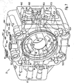
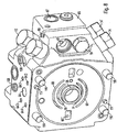
- Fig. 7 shows the terminal block 25 from the side on which the auxiliary pump 9 is arranged.
- a suction kidney 106 and a Hilfstikniere 107 are introduced in the recessed area, which accommodates the auxiliary pump 9, a suction kidney 106 and a Hilfstikniere 107 are introduced.
- the Hilfstikniere 107 is connected via the auxiliary pressure channel 86 to the feed pressure channel 80, as with reference to Fig. 3 has already been explained.
- the suction kidney 106 is connected via a suction channel 108 to the terminal 88, to which in turn the suction line 1 is connected.
- FIG Fig. 8 A perspective view of the terminal block is shown in FIG Fig. 8 shown.
- the feeders 13, 13 ', 14 and 14' which are designed as cartridges, inserted into the corresponding recesses 76 to 79.
- the pressure limiting valve 19 is inserted into the Niedertownventilaus Principleung 84.
- the terminal block 25 is a preassembled unit in which all the components are already present, which are required on the one hand for feeding the two hydraulic circuits when starting the piston engine and on the other hand an increase in the pressure in the working lines over a critical value for each working line 7, 8, 7 'and 8' individually prevent.
- the measuring connections are closed with plugs 109. From the mounting holes 105 protrude in the direction of the hydrostatic piston engine screws 110 and introduced into corresponding recesses in the front side dowel pins 111 for the exact definition of the position of the terminal block 25 with respect to the hydrostatic piston engine out.
- the arrangement described not only allows a high degree of integration with respect to the functionality of the terminal block 25, but due to the guidance of the individual channels, as well as the arrangement of the corresponding terminals on the outside of the terminal block 25, to keep the overall length of the terminal block 25 small.
- all valves, where maintenance may possibly be required are arranged on only one side of the terminal block 25. This results in a simplified maintenance, since in the assembled state, the valves are all accessible from the same side.
- no lines have to be dismantled since all the necessary connections are formed as channels in the interior of the connection block 25 and the valves used are used only in recesses provided for this purpose as cartridges.
Landscapes
- Engineering & Computer Science (AREA)
- Mechanical Engineering (AREA)
- General Engineering & Computer Science (AREA)
- Reciprocating Pumps (AREA)
Abstract
Description
- Die Erfindung betrifft einen Anschlussblock für eine hydrostatische Kolbenmaschine, die zum gleichzeitigen Betrieb in einem ersten und in einem zweiten hydraulischen Kreislauf vorgesehen ist.
- Eine Axialkolbenmaschine, die zum Betrieb in einem ersten und in einem zweiten hydraulischen Kreislauf geeignet ist, ist aus der
DE 34 13 867 A1 bekannt. Zum Verbinden der Arbeitsleitungen der beiden hydraulischen Kreisläufe ist ein Anschlussblock vorgesehen, in dem Arbeitsdruckkanäle angeordnet sind. Die Arbeitsdruckkanäle münden an der Stirnseite des Anschlussblocks zu einer Steuerplatte hin aus, in der Steuernieren ausgebildet sind. Über die Steuernieren sind Zylinderräume einer drehbar gelagerten Zylindertrommel bei Rotation der Zylindertrommel zeitweilig mit den Arbeitsleitungen verbunden. - Nachteilig dabei ist es, dass in dem Anschlussblock nur die Anschlusskanäle vorgesehen sind und der Anschlussblock damit ausschließlich der Verbindung der hydrostatischen Kolbenmaschine mit den Arbeitsleitungen dient. Eine Einspeisung von Druckmittel beim Anfahren der Kolbenmaschine muss dagegen durch zusätzliche Leitungsverbindungen vorgenommen werden. Damit erhöht sich der Aufwand beim Aufbau der hydraulischen Anlage. Insbesondere steigt durch die außerhalb des Anschlussblocks geführten Leitungen der erforderliche Bauraum, womit sich gleichzeitig die zugänglichkeit für Wartungsmaßnahmen verschlechtert.
- Die
US 2002/0157391 A1 zeigt eine hydrostatische Kolbenmaschine mit einem Anschlussblock gemäβ dem Oberbegriff von Anspruch 1. Die Kolbenmaschine ist zum Betrieb in zwei Kreisläufen geeignet. Im Anschlussblock sind ein erster und ein zweiter Arbeitsdruckkanal ausgebildet, über die eine erste bzw. zweite Arbeitsleitung des hydraulischen Kreislaufs mit eine ersten bzw. zweiten Steuerniere einer Steuerplatte verbindbar sind. Im Anschlussblock ist ein dritter und ein vierter Arbeitsdruckkanal ausgebildet, über die eine dritte bzw. vierte Arbeitsleitung des hydraulischen Kreislaufs mit einer dritten bzw. vierten Steuerniere einer Steuerplatte verbindbar sind. - Es ist die Aufgabe der Erfindung einen Anschlussblock für eine hydrostatische Kolbenmaschine zu schaffen, die eine kompakte hydraulische Anlage ermöglicht.
- Die Aufgabe wird durch den erfindungsgemäßen Anschlussblock mit den Merkmalen des Anspruchs 1 gelöst.
- Bei dem erfindungsgemäßen Anschlussblock ist neben den Arbeitsdruckkanälen zusätzlich in dem Anschlussblock ein Speisedruckkanal ausgebildet. Dieser Speisedruckkanal ist über jeweils eine separate Speiseeinrichtung mit einem Arbeitsdruckkanal verbindbar. Durch die Integration des Speisedruckkanals in den Anschlussblock werden zusätzliche Leitungen außerhalb des Anschlussblocks vermieden. Der Anschlussblock ist eine kompakte Einheit, die gemeinsam mit der hydrostatischen Kolbenmaschine in einer hydraulischen Anlage verbaut wird, ohne dass eine zusätzliche Zuführung des Speisedrucks außerhalb der hydrostatischen Kolbenmaschine und des Anschlussblocks zu den Arbeitsleitungen erfolgt.
- Die in den Unteransprüchen ausgeführten Maßnahmen betreffen vorteilhafte Weiterbildungen des erfindungsgemäßen Anschlussblocks.
- Insbesondere ist es vorteilhaft, auch die Speiseeinrichtungen mit in den Anschlussblock zu integrieren. Dazu sind in dem Anschlussblock Ausnehmungen ausgebildet, in die die Speiseeinrichtungen einsetzbar sind. Die Speiseeinrichtungen sind hierfür als eine kompakte Einheit mit den für die Speisung erforderlichen Ventilen ausgebildet, die als eine Baugruppe, die sogenannte Patrone, gemeinsam in die entsprechende Ausnehmung in den Anschlussblock eingeschraubt werden kann.
- Weiterhin ist es vorteilhaft, jede Speiseeinrichtung mit einem Hochdruckbegrenzungsventil zu versehen. Damit ist jedem Arbeitsdruckkanal ein eigenes Hochdruckbegrenzungsventil zugeordnet. Eine Entlastung kann bei Überschreiten eines Druckgrenzwerts in einer einzelnen Arbeitsleitung getrennt von den übrigen Arbeitsleitungen bzw. den damit verbundenen Arbeitsdruckkanälen erfolgen. Sowohl die Einspeisung als auch die Hochdruckegrenzung sind damit in den Anschlussblock integriert.
- Weiterhin ist es vorteilhaft, zumindest für einen hydraulischen Kreislauf die beiden Arbeitsdruckkanäle so in dem Anschlussblock anzuordnen, dass die beiden Anschlüsse an einer Seite des Anschlussblocks liegen. An einer anderen Seite des Anschlussblocks wird damit die Anordnung aller Speiseeinrichtungen ermöglicht. Die Nähe der gemeinsamen Anordnung der Speiseeinrichtungen führt wiederum zu einer günstigen, etwa symmetrischen Geometrie des Speisedruckkanals. Eine weitergehende Integration wird durch das Anordnen einer Hilfspumpe in dem Anschlussblock erreicht.
- Die Hilfspumpe ist in einer Ausnehmung des Anschlussblocks angeordnet, wobei die Hilfspumpe vorzugsweise als Sichelpumpe ausgeführt ist, deren Hochdruckniere innerhalb des Anschlussblocks mit dem Speisedruckkanal verbunden ist.
- Eine bevorzugte Ausführungsform des erfindungsgemäßen Anschlussblocks ist in der Zeichnung dargestellt und wird in der nachfolgenden Beschreibung näher erläutert. Es zeigen:
- Fig. 1
- einen hydraulischen Schaltplan einer in zwei hydraulischen Kreisläufen betriebenen hydrostatischen Kolbenmaschine,
- Fig. 2
- eine Schnittdarstellung einer hydrostatischen Kolbenmaschine zum Betrieb in zwei hydraulischen Kreisläufen,
- Fig. 3
- eine erste perspektivische Darstellung eines Ausführungsbeispiels eines erfindungsgemäßen Anschlussblocks,
- Fig. 4
- eine erste Draufsicht des Ausführungsbeispiels des erfindungsgemäßen Anschlussblocks,
- Fig.5
- eine zweite perspektivische Darstellung des Ausführungsbeispiels eines erfindungsgemäßen Anschlussblocks,
- Fig. 6
- eine dritte perspektivische Darstellung des Ausführungsbeispiels eines erfindungsgemäßen Anschlussblocks,
- Fig. 7
- eine vierte perspektivische Darstellung des Ausführungsbeispiels eines erfindungsgemäßen Anschlussblocks und
- Fig. 8
- eine Außenansicht eines Anschlussblocks als vormontierte Einheit.
- Bevor auf die konstruktive Ausgestaltung eines Ausführungsbeispiels einer erfindungsgemäßen hydrostatischen Kolbenmaschine 1 ausführlich eingegangen wird, soll zunächst der prinzipielle Aufbau einer an zwei hydrostatischen Kreisläufen betriebenen Kolbenmaschine 1 anhand des hydraulischen Schaltplans in
Fig. 1 erläutert werden. Im dargestellten Ausführungsbeispiel umfasst die hydrostatische Kolbenmaschine 1 eine Pumpe 2 zum parallelen Fördern von Druckmittel in zwei getrennte, geschlossene hydraulische Kreisläufe. - Die Fördermenge der Pumpe 2 ist durch eine Verstelleinrichtung 3 für beide hydraulische Kreisläufe gemeinsam veränderbar. Die Verstelleinrichtung 3 besteht aus einem Zylinder und einem darin angeordneten Stellkolben 4, der in bekannter Weise an entgegengesetzt zueinander orientierten Kolbenflächen in jeweils einer Stelldruckkammer mit einem Stelldruck beaufschlagt wird. Die beiden Stelldruckkammern sind über jeweils eine Stelldruckleitung 6a, 6b mit einem Stelldruckregelventil 5 verbunden.
- Durch Beaufschlagen der einen Stelldruckkammer und Entlasten der anderen Stelldruckkammer wirkt auf den Stellkolben 4 ein Differenzdruck, durch den der Stellkolben 4 aus seiner Mittellage ausgelenkt wird, in der er durch zwei Zentrierfedern gehalten wird. Durch die Auslenkung des Stellkolbens 4 wird die Pumpe 2 auf ein verändertes Fördervolumen eingestellt. Die Verstellung wirkt gleichermaßen auf den ersten und den zweiten hydraulischen Kreislauf.
- Der erste hydraulische Kreislauf wird aus einer ersten Arbeitsleitung 7 und einer zweiten Arbeitsleitung 8 gebildet. Die Pumpe 2 fördert entweder in die erste Arbeitsleitung 7 oder in die zweite Arbeitsleitung 8. Bei einer Förderung in die erste Arbeitsleitung 7 erfolgt gleichzeitig aufgrund der gemeinsamen Verstellung eine Förderung von Druckmittel in eine dritte Arbeitsleitung 7' des zweiten hydraulischen Kreislaufs oder, bei Förderung in die zweite Arbeitsleitung 8 des ersten hydraulischen Kreislaufs, in eine vierte Arbeitsleitung 8' des zweiten hydraulischen Kreislaufs.
- Der erste hydraulische Kreislauf, bestehend aus dessen erster Arbeitsleitung 7 und dessen zweiter Arbeitsleitung 8, ist hydraulisch von dem zweiten hydraulischen Kreislauf, bestehend aus dessen dritter Arbeitsleitung 7' und dessen vierter Arbeitsleitung 8', unabhängig.
- Beim Anfahren der Pumpe 2 wird zunächst der erste hydraulische Kreislauf und der zweite hydraulische Kreislauf durch eine Hilfspumpe 9 mit Druckmittel gespeist. Die Hilfspumpe 9 saugt hierzu über eine Saugleitung 10 aus einem Tankvolumen 11 Druckmittel an. Zum Filtern des Druckmittels ist in der Saugleitung 10 außerhalb des Gehäuses der hydrostatischen Kolbenmaschine 1 ein Filter 12 angeordnet, das das angesaugte Druckmittel von Verunreinigungen befreit.
- Zum Einspeisen in den ersten hydraulischen Kreislauf ist eine erste Speiseeinrichtung 13 und eine zweite Speiseeinrichtung 14 vorgesehen, wobei die erste Speiseeinrichtung 13 mit der ersten Arbeitsleitung 7 des ersten hydraulischen Kreislaufs und die zweite Speiseeinrichtung 14 mit der zweiten Arbeitsleitung 8 des ersten hydraulischen Kreislaufs verbunden ist. Analog dazu ist eine dritte Speiseeinrichtung 13' mit der dritten Arbeitsleitung 7' des zweiten hydraulischen Kreislaufs und eine vierte Speiseeinrichtung 14' mit der vierten Arbeitsleitung 8' des zweiten hydraulischen Kreislaufs verbunden.
- Die erste bis vierte Speiseeinrichtung 13, 13', 14 und 14' sind gemeinsam mit einem Speisedruckkanal 15 verbunden, in den die Hilfspumpe 9 das angesaugte Druckmittel fördert. In bekannter Weise ist, wie es in der
Fig. 1 lediglich bei der vierten Speiseeinrichtung 14' mit Bezugszeichen illustriert ist, in den Speiseeinrichtungen 13 bis 14' jeweils ein Rückschlagventil 17 angeordnet, welches zum Einspeisen von Druckmittel einen Strömungsweg von dem Speisedruckkanal 15 in Richtung der jeweils angeschlossenen Arbeitsleitung 7, 8, 7' oder 8' öffnet, solange der Druck in dem Speisedruckkanal 15 größer ist als der jeweilige Arbeitsdruck. Parallel zu dem Rückschlagventil 17 ist jeweils ein Hochdruckbegrenzungsventil 18 in den Speiseeinrichtungen 13, 13', 14 und 14' angeordnet. Bei Überschreiten eines kritischen Drucks in der jeweiligen Arbeitsleitung 7, 8, 7', oder 8' öffnet das jeweilige Hochdruckbegrenzungsventil 18 in Richtung des Speisedruckkanals 15. - Steigt z. B. beim Öffnen eines solchen Hochdruckbegrenzungsventils 18 der Druck in dem Speisedruckkanal 15 an, so wird oberhalb eines Grenzwertes für den Speisedruck ein Druckbegrenzungsventil 19 geöffnet, durch welches der Speisedruckkanal 15 in das Tankvolumen 11 entspannt wird. Damit wird in dem Speisedruckkanal 15 ein definiertes Druckniveau aufrechterhalten, da auch bei gestiegener Förderleistung z. B. durch Erhöhen der Hilfspumpendrehzahl, das Druckbegrenzungsventil 18 öffnet.
- Das Stelldruckregelventil 5 ist als 4/3-Wegeventil ausgeführt, welches kontinuierlich verstellbar ist. Zum Einstellen einer bestimmten Position wird das Stelldruckregelventil 5 ausgehend von seiner Neutrallage, in der es durch Druckfedern gehalten wird, mit einer in axialer Richtung wirkenden Kraft beaufschlagt. Diese Kraft wird als Kraftdifferenz zwischen zwei Proportionalmagneten 20a und 20b erzeugt, die mit jeweils einer Druckfeder gleichsinnig auf einen Ventilkolben des Stelldruckregelventils 5 wirken. Die jeweils eingeregelte Position des Stellkolbens 4 wird bei der Regelung des Stelldrucks berücksichtigt, indem eine Ventilhülse des Stelldruckregelventils 5 mit dem Stellkolben 4 über eine Koppelstange 21 verbunden ist.
- Um die Stelldruckkammern mit einem Stelldruck beaufschlagen zu können, ist das Stelldruckregelventil 5 über eine Stelldruckzuführung 16 mit dem Speisedruckkanal 15 verbunden. Die Verstelleinrichtung 3 kann damit beim Anfahren der Pumpe 2 ab dem Zeitpunkt betätigt werden, zu dem die Hilfspumpe 9 einen Druck in dem Speisedruckkanal 15 aufgebaut hat. Die Verstelleinrichtung 3 kann damit unabhängig von der von der Pumpe 2 in den ersten hydraulischen Kreislauf bzw. zweiten hydraulischen Kreislauf geförderten Druckmittelmenge betätigt werden.
- Die Hilfspumpe 9 und die Pumpe 2 sind im dargestellten Ausführungsbeispiel durch eine gemeinsame Antriebswelle 22 angetrieben.
- In dem in
Fig. 2 dargestellten Längsschnitt der erfindungsgemäßen hydrostatischen Kolbenmaschine ist gezeigt, wie die gemeinsame Antriebswelle 22 durch ein Rollenlager 23 an einem Ende eines Pumpengehäuses 24 gelagert ist. Zusätzlich ist die gemeinsame Antriebswelle 22 in einem Gleitlager 26 gelagert, welches in einem Anschlussblock 25 angeordnet ist, der das Pumpengehäuse 24 an dem gegenüberliegenden Ende verschließt. - In dem Anschlussblock 25 ist eine, den Anschlussblock vollständig in axialer Richtung durchdringende Ausnehmung 33 ausgebildet, in der zum einen das Gleitlager 26 angeordnet ist und die zum anderen von der gemeinsamen Antriebswelle 22 durchdrungen ist. Auf der von dem Pumpengehäuse 24 abgewandten Seite des Anschlussblocks 25 ist in eine radiale Erweiterung der Ausnehmung 33 die hilfspumpe 9 eingesetzt. Zum Antreiben der Hilfspumpe 9 weist die gemeinsame Antriebswelle 22 eine Verzahnung 27.1 auf, die mit der entsprechenden Verzahnung der Hilfspumpenwelle 28 im Eingriff ist. Die Hilfspumpenwelle 28 ist in der Ausnehmung 33 durch ein erstes Hilfspumpengleitlager 34 und durch ein zweites Hilfspumpengleitlager 35 in der Hilfspumpenanschlussplatte 31 gelagert.
- Auf der Hilfspumpenwelle 28 ist ein Zahnrad 29 angeordnet, welches im Eingriff mit einem Hohlrad 30 ist. Über das Zahnrad 29 wird das Hohlrad 30, das drehbar in der Hilfspumpenanschlussplatte 31 angeordnet ist, ebenfalls von der Hilfspumpenwelle 28 und damit letztlich von der gemeinsamen Antriebswelle 22 angetrieben. In der Hilfspumpenanschlussplatte 31 sind der saug- und der druckseitige Anschluss für die Hilfspumpe 9 ausgebildet. Die Hilfspumpe 9 wird durch einen Deckel 32, der an dem Anschlussblock 25 montiert ist, in der radialen Erweiterung der Ausnehmung 33 des Anschlussblocks 25 fixiert.
- Bei einer besonders bevorzugten Ausführungsform des erfindungsgemäßen Anschlussblocks 25 sind der saug- und der druckseitige Anschluss in dem Anschlussblock 25 ausgebildet, wie es nachfolgend noch bei der detaillierten Beschreibung des erfindungsgemäßen Anschlussblocks 25 anhand der
Fig. 3 bis 8 erläutert wird. - Der Innenring des Rollenlagers 23 ist in axialer Richtung auf der gemeinsamen Antriebswelle 22 fixiert. Der Innenring liegt einerseits an einem Bund 36 der gemeinsamen Antriebswelle 22 an und ist auf der anderen Seite durch einen Sicherungsring 37 in dieser axialen Position gehalten, der in einer Nut der gemeinsamen Antriebswelle 22 eingesetzt ist. Die axiale Position des Rollenlagers 23 bezüglich des Pumpengehäuses 24 wird durch einen Sicherungsring 38 bestimmt, der in eine umlaufende Nut der Wellenöffnung 39 eingesetzt ist. In Richtung der Außenseite des Pumpengehäuses 24 ist in der Wellenöffnung 39 außerdem ein Dichtring 40 und abschließend ein weiterer Sicherungsring 41 angeordnet, wobei der Sicherungsring 41 in eine umlaufende Nut der Wellenöffnung 39 eingesetzt ist.
- An dem aus dem Pumpengehäuse 24 herausragenden Ende der gemeinsamen Antriebswelle 22 ist eine Antriebsverzahnung 42 ausgebildet, über die die hydrostatische Kolbenmaschine durch eine nicht dargestellte Antriebsmaschine angetrieben wird.
- Im Inneren des Pumpengehäuses 24 ist eine Zylindertrommel 43 angeordnet, die eine zentrale Durchgangsöffnung 44 aufweist, welche von der gemeinsamen Antriebswelle 22 durchdrungen wird. Über eine weitere Antriebsverzahnung 45 ist die Zylindertrommel 43 verdrehgesichert, aber in axialer Richtung verschiebbar mit der gemeinsamen Antriebswelle 22 verbunden, so dass sich eine Drehbewegung der gemeinsamen Antriebswelle 22 auf die Zylindertrommel 43 überträgt.
- In eine in der zentralen Durchgangsöffnung 44 ausgebildeten Nut ist ein weiterer Sicherungsring 46 eingesetzt, an dem eine erste Stützscheibe 47 anliegt. Die erste Stützscheibe 47 bildet ein erstes Federlager für eine Druckfeder 48 aus. Ein zweites Federlager für die Druckfeder 48 wird durch eine zweite Stützscheibe 49 gebildet, die sich an der Stirnseite der weiteren Antriebsverzahnung 45 abstützt. Die Druckfeder 48 übt damit einerseits auf die gemeinsame Antriebswelle 42 und andererseits auf die Zylindertrommel 43 jeweils eine Kraft in entgegengesetzt axialer Richtung aus. Die gemeinsame Antriebswelle 22 wird so belastet, dass der Außenring des Rollenlagers 23 sich an der Scheibe 38 abstützt.
- In entgegengesetzter Richtung wirkt die Druckfeder 48 auf die Zylindertrommel 43, die mit einer an der Stirnseite der Zylindertrommel 43 ausgebildeten sphärischen Vertiefung 51 in Anlage an einer Steuerplatte 52 gehalten wird. Die-Steuerplatte 52 liegt wiederum mit der von der Zylindertrommel 43 abgewandten Seite dichtend an dem Anschlussblock 25 an. Durch die sphärische Vertiefung 51, die mit einer entsprechenden sphärischen Ausformung der Steuerplatte 52 korrespondiert, wird die Zylindertrommel 43 zentriert. Die Steuerplatte 52 kann auch eben ausgeführt sein.
- Die Position der Steuerplatte 52 in radialer Richtung wird durch den äußeren Umfang des Gleitlagers 26 festgelegt. Das Gleitlager 26 ist zu diesem Zweck nur zum Teil in die Ausnehmung 33 in den Anschlussblock 25 eingesetzt.
- In die Zylindertrommel 43 sind über einen gemeinsamen Teilkreis verteilt Zylinderbohrungen 53 eingebracht, in denen Kolben 54' angeordnet sind, die in den Zylinderbohrungen 53 längsverschieblich sind. An dem von der sphärischen Vertiefung 51 abgewandten Ende ragen die Kolben 54 teilweise aus der Zylindertrommel 43 heraus. An diesem Ende ist an den Kolben 54 jeweils ein Gleitschuh 55 befestigt, über den sich die Kolben 54 auf einer Lauffläche 56 einer Schwenkscheibe 57 abstützen.
- Zum Erzeugen einer Hubbewegung der Kolben 54 ist der Winkel, den die Lauffläche 56 der Schwenkscheibe 57 mit der Mittelachse einschließt, veränderbar. Die Schwenkscheibe 57 kann hierzu durch die Verstelleinrichtung 3 in ihrer Neigung verstellt werden.
- Zum Aufnehmen der Kräfte, die durch die Gleitschuhe 55 auf die Schwenkscheibe 57 übertragen werden, ist die Schwenkscheibe 57 in dem Pumpengehäuse 24 rollengelagert.
- Zum Anschließen der hydrostatischen Kolbenmaschine 1 an einen ersten hydraulischen Kreislauf und an einen zweiten hydraulischen Kreislauf sind in dem Anschlussblock 25 schematisch ein erster Anschluss 58 für eine erste Arbeitsleistung und ein zweiter Anschluss 58' für eine zweite Arbeitsleitung dargestellt, die in nicht gezeigter Weise über die Steuerplatte 52 mit den Zylinderbohrungen 53 verbindbar sind.
-
Fig. 3 zeigt eine perspektivische Darstellung eines erfindungsgemäßen Anschlussblocks 25. Der Anschlussblock 25 ist im wesentlichen von der Seite der Steuerplatte 52 aus dargestellt. In dem Anschlussblock 25 sind ein erster Arbeitsdruckkanal 60 und ein zweiter Arbeitsdruckkanal 61 angeordnet. Der erste Arbeitsdruckkanal 60 und der zweite Arbeitsdruckkanal 61 sind dem ersten hydraulischen Kreislauf zugeordnet. Dem zweiten hydraulischen Kreislauf sind ein dritter Arbeitsdruckkanal 62 und ein vierter Arbeitsdruckkanal 63 zugeordnet. Die vier Arbeitsdruckkanäle 60 bis 63 verbinden je nach Arbeitsrichtung der Pumpe 2 die saug- bzw. druckseitigen Arbeitsleitungen 7, 7', 8 und 8' des ersten bzw. zweiten hydraulischen Kreislaufs mit den entsprechenden Steuernieren der Steuerplatte 52. - An dem auf der Außenseite des Anschlussblocks 25 ausgebildeten Ende des Arbeitsdruckkanals 60 ist ein erster Anschluss 64 ausgebildet, an dem die erste Arbeitsleitung 7 des ersten hydraulischen Kreislaufs anschließbar ist. Zum Anschluss der zweiten Arbeitsleitung 8 des ersten hydraulischen Kreislaufs ist an der bezüglich der Längsachse des Anschlussblocks 25 diametral gegenüberliegenden Seite an dem an der Außenseite befindlichen Ende des zweiten Arbeitsdruckkanals 61 ein zweiter Anschluss 65 ausgebildet.
- Dementsprechend ist auch für den dritten Arbeitsdruckkanal 62 und den vierten Arbeitsdruckkanal 63 ein dritter anschluß 66 und ein vierter Anschluss 67 an der Außenseite des Anschlussblocks 25 ausgebildet. Der dritte Anschluss 66 und der vierte Anschluss 67 sind jedoch an derselben Seite des Anschlussblocks 25 angeordnet. Die jeweils von den Anschlüssen 64 bis 67 abgewandten Enden der Arbeitsdruckkanäle 60 bis 63 münden in einer Fläche des Anschlussblocks 25 aus, an der die Steuerplatte 52 dichten anliegt. Die Ausmündungen sind nierenförmig. Die Lage der Ausmündungen des ersten Arbeitsdruckkanals 60 und des zweiten Arbeitsdruckkanals 61 korrespondiert mit der Lage einer ersten Steuerniere und einer zweiten Steuerniere in der Steuerplatte 52 und sind in der Zeichnung mit den Bezugszeichen 68 und 69 versehen.
- Während die Arbeitsdruckkanäle 60 bis 63 durch Einsetzen von entsprechenden Formteilen bereits während des Gießvorgangs eines Rohteils des Anschlussblocks 25 erzeugt werden, werden die Anschlüsse 64 und 65 nachträglich mit vorzugsweise spanabhebenden Verfahren erzeugt, um eine ausreichende Oberflächenqualität für eine dichtende Verbindung mit der ersten und der zweiten Arbeitsleitung 7 und 8 sicherzustellen. Die nierenförmigen Ausmündungen 68 und 69 werden ebenfalls in das gegossene Rohteil eingebracht, z.B. durch Fräsen. Die nachfolgend noch zu beschreibenden, an der Außenseite des Anschlussblocks 25 liegenden Anschlüsse und Ausnehmungen werden ebenfalls spanabhebend erzeugt, wobei die damit verbundenen Kanäle jeweils bereits beim Gießen des Rohteils durch Formteile erzeugt werden.
- In der in der
Fig. 3 nicht dargestellten Steuerplatte 52 sind weiterhin eine dritte Steuerniere 70' und eine vierte Steuerniere 71' ausgebildet, welche sich entlang jeweils eines Abschnitts eines weiteren Kreisbogens mit einem kleineren Durchmesser erstrecken. Entsprechende Ausmündungen 70 und 71 des dritten Arbeitsdruckkanals 62 und des vierten Arbeitsdruckkanals 63 korrespondieren mit der Lage der dritten Steuerniere 70' und der vierten Steuerniere 71' in der Steuerplatte 52. Die Ausmündungen 68 bis 71 der Arbeitsdruckkanäle 60 bis 63 sind damit durchströmbar mit den Steuernieren 68 bis 71 verbunden. - Der erste Arbeitsdruckkanal 60 ist über einen ersten Verbindungskanal 72 mit einer ersten Ausnehmung 76 verbunden. Dementsprechend sind auch der zweite, dritte und vierte Arbeitsdruckkanal 61, 62 und 63 über jeweils einen zweiten, dritten und vierten Verbindungskanal 73, 74 und 75 mit einer zweiten, dritten und vierten Ausnehmung 77, 78 und 79 verbunden.
- Weiterhin ist mit der ersten bis vierten Ausnehmung 76 bis 79 ein gemeinsamer Speisedruckkanal 80 verbunden. Die erste bis vierte Ausnehmung 76 bis 79 sind zur Aufnahme von den in der
Fig. 3 nicht dargestellten Speiseeinrichtungen 13, 14, 13' und 14' vorgesehen. Wie es bei der Erläuterung des hydraulischen Schaltplans inFig. 1 bereits ausgeführt wurde, enthalten die Speiseeinrichtungen 13, 14, 13' und 14' jeweils ein Rückschlagventil 17, welches in Richtung des jeweiligen Arbeitsdruckkanals 60 bis 63 öffnet. Bei geöffnetem Rückschlagventil 17 strömt Druckmittel aus dem gemeinsamen Speisedruckkanal 80 in den entsprechenden Arbeitsdruckkanal 60 bis 63, solange der Druck in dem Speisedruckkanal 80 höher ist, als in der jeweiligen Arbeitsleitung 7, 8, 7' bzw. 8'. - Die Drücke in den vier Arbetisleitungen 7, 8, 7' und 8' sind über einen ersten bis vierten Messanschluss separat messbar. Zum Erfassen des in der zweiten Arbeitsleitung 8 des ersten hydraulischen Kreislaufs herrschenden Drucks zweigt von dem zweiten Verbindungskanal 73 ein zweiter Messkanal 81 ab, der an der Gehäuseaußenseite einen zweiten Messanschluss 82 mündet. Der zum Messen des Arbeitsleitungsdrucks der ersten Arbeitsleitung 7 vorgesehene erste Messanschluss wird unter Bezugnahme auf die nachfolgenden Figurenbeschreibung noch erläutert.
- Die zur Aufnahme der Speiseeinrichtungen 13 und 14 des ersten hydraulischen Kreislaufs vorgesehene erste Ausnehmung 76 und die zweite Ausnehmung 77 sind V-förmig angeordnet und auf der von dem dritten Anschluss 66 und dem vierten Anschluss 67 abgewandten Seite in den Anschlussblock 25 eingebracht. Die dritte Ausnehmung 78 und die vierte Ausnehmung 79 sind ebenfalls V-förmig mit einem vorzugsweise identischen Öffnungswinkel angeordnet. Die dem zweiten hydraulischen Kreislauf zugeordnete dritte Ausnehmung 78 und vierte Ausnehmung 79 sind in axialer Richtung bezüglich der Längsachse versetzt zu der ersten Ausnehmung 76 und der zweiten Ausnehmung 77 angeordnet. Dementsprechend erstreckt sich auch der Speisedruckkanal 80 in axialer Richtung. Die Verbindung des Speisedruckkanals 80 mit den Ausnehmungen 76 bis 79 erfolgt über jeweils einen Speisedruckverbindungskanal 76' bis 79'. In der
Fig. 3 sind im Vordergrund lediglich die zu der ersten Ausnehmung 76 und der zweiten Ausnehmung 77 führenden Speisedruckverbindungskanäle 76' und 77' zu sehen, während die beiden übrigen Speisedruckverbindungskanäle 78' und 79' der dritten und vierten Ausnehmung 78 und 79 verdeckt sind. - In einem Fortsatz 85 des Anschlussblocks 25 sind weiterhin eine Regelventilausnehmung 83 und eine Niederdruckventilausnehmung 84 angeordnet. In die Regelventilausnehmung 83 kann ein in
Fig. 1 dargestelltes Regelventil 120 eingesetzt, vorzugsweise eingeschraubt werden. Die Regelventilausnehmung 83 und die Niederdruckventilausnehmung 84 sind parallel zu der Längsachse orientiert in den Fortsatz 85 eingebracht und stehen jeweils ebenfalls mit dem Speisedruckkanal 80 über einen Anschlusskanal 80' in Verbindung. Die Regelventilausnehmung 83 ist zur Aufnahme einer Patrone vorgesehen, die abhängig von der Antriebsdrehzahl der Pumpe einen drehzahlabhängigen Steuerdruck erzeugt. In die Niederdruckventilausnehmung 84 wird dagegen das Druckbegrenzungsventil 19 eingesetzt. - Im Hintergrund der
Fig. 3 ist ein Hilfsdruckkanal 86 zu erkennen, der einen Hilfsdruckausgang der Hilfspumpe 9 mit dem Speisedruckkanal 80 verbindet. Der Hilfsdruckkanal 86 wird seitlich durch den Fortsatz 85 hindurch aus dem Anschlussblock 25 herausgeführt, wobei dessen Öffnung 87 im Betrieb mit einem Stopfen verschlossen ist, sofern vorgesehen ist, in dem Anschlussblock 25 eine Hilfspumpe 9 zu betreiben. Wird eine externe Hilfsdruckquelle verwendet, so wird dessen Hilfsdruckzuleitung an dem Hilfsdruckkanal 86 angeschlossen. - Die Anordnung der ersten bis vierten Ausnehmung 76 bis 79, sowie der Stelldruckregelventilausnehmung 83 und der Niederdruckventilausnehmung 84 ist etwa symmetrisch bezüglich einer durch einen ersten Trennsteg 101 und einen zweiten Trennsteg 102 verlaufende Symmetrieebene 103.
- In
Fig. 4 ist eine Draufsicht auf die zu der Steuerplatte 52 gewandten Seite des Anschlussblocks 25 dargestellt. Es ist lediglich die erste Ausnehmung 76 und die zweite Ausnehmung 77 sowie der erste Verbindungskanal 72 und der zweite Verbindungskanal 73 zu erkennen. Die äquivalenten Ausnehmungen bzw. Verbindungskanäle für den zweiten hydraulischen Kreislauf sind in der Darstellung derFig. 4 nicht zu sehen, da sie verdeckt, in axialer Richtung versetzt dazu angeordnet sind. Zu erkennen ist weiterhin, dass die Regelventilausnehmung 83 sich mit dem Hilfsdruckkanal 86 schneidet, so dass dem in die Regelventilausnehmung 83 eingesetzten Regelventil über den Hilfsdruckkanal 86 der von der Hilfspumpe 9 erzeugte Speisedruck zugeführt wird. - Von dem zweiten Anschluss 65 teilweise verdeckt ist ein Sauganschluss 88 zu erkennen, der mit einer Saugniere der Hilfspumpe 9 verbunden ist. Um das in der Ausnehmung 33 angeordnete Gleitlager 26 mit Druckmittel zur Schmierung zu versehen, sind eine Querbohrung 89' und eine Längsbohrung 89" so in dem Anschlussblock 25 angeordnet, dass eine durchgehende Verbindung von der Stirnseite des Anschlussblocks 25 zu der Ausnehmung 33 führt.
- Zum Abführen von Leckagedruckmittel durchdringt eine Leckölbohrung 90 die Regelventilausnehmung 83 und mündet in einen Ablaufkanal 91, der von der Außenseite her durch Bohren in den Fortsatz 85 eingebracht ist und mit der Niederdruckventilausnehmung 84 verbunden ist. Über den Ablaufkanal 91 wird sowohl das Lecköl des Regelventils als auch das durch die Entlastung bei geöffnetem Druckbegrenzungsventil 19 abfließende Druckmittel in das Gehäusevolumen abgeführt.
- Weiterhin ist in der
Fig. 4 zu erkennen, dass sich der erste Arbeitsdruckkanal 60 und der zweite Arbeitsdruckkanal 61 in Richtung der Ausmündungen 68 und 69 verbreitern und der erste und der zweite Verbindungskanal 72 und 73 in diesem verbreiterten Bereich von der Seite des Fortsatzes 85 her einmünden. - In
Fig. 5 ist eine Seitenansicht der Seite des ersten Anschlusses 64 dargestellt. Gut zu erkennen sind die axial versetzte Anordnung der ersten Ausnehmung 76 und der zweiten. Ausnehmung 78 sowie der Verlauf des ersten Verbindungskanals 72 und des dritten Verbindungskanals 74. Zum Messen des in dem ersten Arbeitsdruckkanal 60 und in der damit verbundenen ersten Arbeitsleitung 7 des ersten hydraulischen Kreislaufs herrschenden Drucks ist ein erster Messanschluss 97 vorgesehen, der über eine erste Verbindungsbohrung 92 mit dem ersten Arbeitsdruckkanal 60 verbunden ist. - Zum Messen des in der dritten Arbeitsleitung 7' herrschenden Drucks ist ein dritter Messanschluss 93 vorgesehen. Der dritte Messanschluss 93 ist an dem an der Außenseite des Anschlussblocks 25 angeordneten Ende einer Messbohrung ausgebildet, die in den dritten Verbindungskanal 74 mündet und so mit diesem verbunden ist.
- In der
Fig. 5 ist weiterhin ein System aus sich schneidenden Bohrungen 104 ausgebildet, die gemeinsam ein Steuerkanalsystem bilden. Um ein abgeschlossenes Steuerkanalsystem zu erzeugen, werden die Bohrungen an der Außenseite des Anschlussblocks 25 mit Stopfen verschlossen. - Um den ersten Anschluss 64 herum sind in den Anschlussblock 25 vier Sacklöcher 64.1 bis 64.4 eingebracht, die mit einem Gewinde versehen zur Befestigung der ersten Arbeitsleitung 7 dienen.
- Zur Befestigung des gesamten Anschlussblocks 25 an einer Kolbenmaschine durchdringen in axialer Richtung Befestigungsbohrungen 105 den Anschlussblock, wobei zwei Befestigungsbohrungen in der
Fig. 5 dargestellt und mit den Bezugszeichen 105.1 und 105.2 versehen sind. -
Fig. 6 zeigt eine Seitenansicht der der in der Darstellung derFig. 5 gezeigten Seite gegenüberliegenden Seite. Dort ist der zweite Messanschluss 81 gezeigt, der über eine Messbohrung direkt mit dem zweiten Verbindungskanal 73 verbunden ist. Weiterhin ist ein vierter Messanschluss 94 gezeigt, der ebenfalls über eine Messbohrung direkt mit dem vierten Verbindungskanal 75 verbunden ist. Zwischen dem zweiten Messanschluss 81 und dem vierten Messanschluss 94 ist ein Hilfsdruckanschluss 95 ausgebildet, der über eine Bohrung 95' mit dem Speisedruckkanal 80 verbunden ist. Über den Hilfsdruckanschluss 95 können z. B. weitere hydraulische Verbraucher mit dem Speisedruck der Hilfspumpe 9 versorgt werden. - In dieser Ansicht sind auch die beiden übrigen Befestigungsbohrungen 105.3 und 105.4 gezeigt. Sämtliche Befestigungsbohrungen 105 weisen an der zur Hilfspumpe 9 weisendenden Seite eine Vergrößerung des Durchmessers auf, die ein Versenken der Befestigungsschrauben, die in ein in dem nicht dargestellten Gehäuse der Kolbenmaschine vorgesehene Gewinde geschraubt werden, ermöglichen.
- Zur Befestigung der zweiten Arbeitsleitung 8 an dem Anschlussblock 25 sind wiederum vier Sacklöcher 65.1 bis 65.4 um den zweiten Anschluss 65 herum in den Anschlussblock 25 eingebracht.
-
Fig. 7 zeigt den Anschlussblock 25 von der Seite, an der die Hilfspumpe 9 angeordnet ist. In dem vertieften Bereich, der die Hilfspumpe 9 aufnimmt, sind eine Saugniere 106 und eine Hilfsdruckniere 107 eingebracht. Die Hilfsdruckniere 107 ist über den Hilfsdruckkanal 86 mit dem Speisedruckkanal 80 verbunden, wie es unter Bezugnahme aufFig. 3 bereits erläutert wurde. Die Saugniere 106 ist über einen Saugkanal 108 mit dem Anschluss 88 verbunden, mit dem wiederum die Saugleitung 1 verbunden ist. - Die im übrigen in der
Fig. 7 dargestellten Kanäle und Bohrungen sind bereits bei der Beschreibung derFig. 3 bis 6 erläutert worden. Um unnötige Wiederholungen zu vermeiden, wird auf eine erneute Beschreibung daher verzichtet. - Eine perspektivische Ansicht des Anschlussblocks ist in
Fig. 8 gezeigt. Dabei sind die Speiseeinrichtungen 13, 13', 14 und 14', die als Patronen ausgeführt sind, in die entsprechenden Ausnehmungen 76 bis 79 eingesetzt. Ferner ist das Druckbegrenzungsventil 19 in die Niederdruckventilausnehmung 84 eingesetzt. Damit ist der Anschlussblock 25 eine vormontierte Einheit, in der bereits sämtliche Bauelemente vorhanden sind, die einerseits zum Speisen der beiden hydraulischen Kreisläufe beim Anfahren der Kolbenmaschine erforderlich sind und die andererseits ein Ansteigen des Drucks in den Arbeitsleitungen über einen kritischen Wert für jede Arbeitsleitung 7, 8, 7' und 8' einzeln verhindern. - Die Messanschlüsse sind mit Stopfen 109 verschlossen. Aus den Befestigungsbohrungen 105 ragen in Richtung der hydrostatischen Kolbenmaschine Schrauben 110 und in entsprechende Ausnehmungen in der Stirnseite eingebrachte Passstifte 111 zur exakten Definition der Lage des Anschlussblocks 25 bezüglich der hydrostatischen Kolbenmaschine heraus.
- Die beschriebene Anordnung ermöglicht nicht nur eine hohe Integration hinsichtlich der Funktionalität des Anschlussblocks 25, sondern erlaubt es aufgrund der Führung der einzelnen Kanäle, sowie der Anordnung der entsprechenden Anschlüsse an der Aussenseite des Anschlussblocks 25, die Baulänge des Anschlussblocks 25 klein zu halten. Außerdem sind sämtiche Ventile, an denen eventuell Wartungsarbeiten erforderlich sein können, an nur einer Seite des Anschlussblocks 25 angeordnet. Damit ergibt sich eine vereinfachte Wartung, da in montiertem Zustand die Ventile allesamt von derselben Seite her zugänglich sind. Es müssen ferner keine Leitungen demontiert werden, da alle erforderlichen Verbindungen als Kanäle im Inneren des Anschlussblocks 25 ausgebildet sind und die verwendeten Ventile lediglich in dafür vorgesehene Ausnehmungen als Patronen eingesetzt werden.
Claims (8)
- Anschlussblock für eine hydrostatische Kolbenmaschine, die zum gleichzeitigen Betrieb in einem ersten hydraulischen Kreislauf und einem zweiten hydraulischen Kreislauf vorgesehen ist,
wobei in dem Anschlussblock ein erster Arbeitsdruckkanal (60) und ein zweiter Arbeitsdruckkanal (61) ausgebildet sind, über die eine erste bzw. eine zweite Arbeitsleitung (7, 8) des ersten hydraulischen Kreislaufs mit einer ersten bzw. einer zweiten Steuerniere (68', 69') einer Steuerplatte (52) der hydrostatischen Kolbenmaschine verbindbar sind und
wobei in dem Anschlussblock (25) ein dritter Arbeitsdruckkanal (62) und ein vierter Arbeitsdruckkanal (63) ausgebildet sind, über die eine dritte bzw. eine vierte Arbeitsleitung (7', 8') des zweiten hydraulischen Kreislaufs mit einer dritten bzw. einer vierten Steuerniere (70', 71') der Steuerplatte (52) der hydrostatischen Kolbenmaschine verbindbar sind,
wobei in dem Anschlussblock (25) ein gemeinsamer Speisedruckkanal (80) vorgesehen ist,
und wobei der gemeinsame Speisedruckkanal (80) mit dem ersten bis vierten Arbeitsdruckkanal (60, 61, 62, 63) jeweils über eine separate Speiseeinrichtung (13, 13', 14, 14') verbindbar ist,
dadurch gekennzeichnet,
dass die Arbeitsdruckkanäle (60, 61, 62, 63) an ihren von den Arbeitsleitungen (7, 8, 7', 8') abgewandten Enden an einer zu der Steuerplatte (52) hin orientierten Stirnfläche des Anschlussblocks (25) nierenförmig ausmünden. - Anschlussblock nach Anspruch 1,
dadurch gekennzeichnet,
dass die Speiseeinrichtungen (13, 13', 14, 14') in Ausnehmungen (76, 77, 78, 79) des Anschlussblocks (25) einsetzbar sind. - Anschlussblock nach Anspruch 1 oder 2,
dadurch gekennzeichnet,
dass in jeder der vier Speiseeinrichtungen (13, 13', 14, 14') ein Hochdruckbegrenzungsventil (18) vorgesehen ist, durch welches bei Überschreiten eines Druckgrenzwerts der Druck in der entsprechenden, mit dem ersten bis vierten Arbeitsdruckkanal (60, 61, 62, 63) verbundenen Arbeitsleitung (7, 8, 7', 8') in den gemeinsamen Speisedruckkanal (80) des Anschlussblocks (25) entlastet wird. - Anschlussblock nach einem der Ansprüche 1 bis 3,
dadurch gekennzeichnet,
dass zumindest der erste und der zweite Arbeitsdruckkanal (60, 61) oder der dritte und der vierte Arbeitsdruckkanal (62, 63) an einer Seite des Anschlussblocks (25) ausmünden. - Anschlussblock nach einem der Ansprüche 1 bis 4,
dadurch gekennzeichnet,
dass die nierenförmigen Ausmündungen (68, 69) des ersten und des zweiten Arbeitsdruckkanals (60, 61) sich entlang eines ersten Teilkreises an der Stirnseite des Anschlussblocks (25) erstrecken. - Anschlussblock nach Anspruch 4 oder 5,
dadurch gekennzeichnet,
dass die nierenförmigen Ausmündungen (70, 71) des dritten und des vierten Arbeitsdruckkanals (62, 63) sich entlang eines zweiten Teilkreises an der Stirnseite des Anschlussblocks (25) erstrecken. - Anschlussblock nach einem der Ansprüche 1 bis 6,
dadurch gekennzeichnet,
dass auf der von der hydrostatischen Kolbenmaschine abgewandten Seite des Anschlussblocks (25) eine Hilfspumpe (9) in den Anschlussblock einsetzbar ist, die in den Speisedruckkanal (80) fördert. - Anschlussblock nach einem der Ansprüche 1 bis 7,
dadurch gekennzeichnet,
dass alle Speiseeinrichtungen (13, 13', 14, 14') auf einer gemeinsamen Seite des Anschlussblocks angeordnet sind.
Applications Claiming Priority (3)
| Application Number | Priority Date | Filing Date | Title |
|---|---|---|---|
| DE10349599 | 2003-10-24 | ||
| DE10349599A DE10349599B3 (de) | 2003-10-24 | 2003-10-24 | Anschlussblock für eine hydrostatische Kolbenmaschine |
| PCT/EP2004/011357 WO2005042973A1 (de) | 2003-10-24 | 2004-10-11 | Anschlussblock für eine hydrostatische kolbenmaschine |
Publications (2)
| Publication Number | Publication Date |
|---|---|
| EP1565652A1 EP1565652A1 (de) | 2005-08-24 |
| EP1565652B1 true EP1565652B1 (de) | 2012-04-11 |
Family
ID=34529752
Family Applications (1)
| Application Number | Title | Priority Date | Filing Date |
|---|---|---|---|
| EP04790264A Expired - Lifetime EP1565652B1 (de) | 2003-10-24 | 2004-10-11 | Anschlussblock für eine hydrostatische kolbenmaschine |
Country Status (4)
| Country | Link |
|---|---|
| US (1) | US7437873B2 (de) |
| EP (1) | EP1565652B1 (de) |
| DE (1) | DE10349599B3 (de) |
| WO (1) | WO2005042973A1 (de) |
Cited By (3)
| Publication number | Priority date | Publication date | Assignee | Title |
|---|---|---|---|---|
| DE102020215991A1 (de) | 2020-12-16 | 2022-06-23 | Robert Bosch Gesellschaft mit beschränkter Haftung | Anschlussblock |
| DE102022200038A1 (de) | 2022-01-05 | 2023-07-06 | Robert Bosch Gesellschaft mit beschränkter Haftung | Anschlussblock |
| DE102023207507A1 (de) * | 2023-08-04 | 2025-02-06 | Robert Bosch Gesellschaft mit beschränkter Haftung | Zentrierung der Gehäuseteile einer Axialkolbenmaschine |
Families Citing this family (8)
| Publication number | Priority date | Publication date | Assignee | Title |
|---|---|---|---|---|
| DE102009037733B4 (de) | 2009-08-17 | 2021-12-09 | Robert Bosch Gmbh | Regelventilanordnung und Verstellpumpe |
| DE102010048068B4 (de) | 2010-04-16 | 2022-11-10 | Robert Bosch Gmbh | Ventilanordnung |
| CN102906416B (zh) * | 2010-04-16 | 2016-05-18 | 罗伯特·博世有限公司 | 用于流体静力的活塞机的连接板 |
| DE102012016068B4 (de) * | 2012-08-14 | 2023-07-20 | Robert Bosch Gmbh | Anschlussvorrichtung für hydrostatische Maschine und hydrostatische Maschine |
| DE102013208453A1 (de) | 2013-05-08 | 2014-11-13 | Robert Bosch Gmbh | Hydrostatische Doppelpumpe, insbesondere Axialkolbendoppelpumpe in Schrägscheibenbauweise |
| DK3137768T3 (da) * | 2014-04-30 | 2021-01-18 | Anthony George Hurter | Anordning og fremgangsmåde til oprensning af brugt brændselsolie med superkritisk vand |
| CN104533741A (zh) * | 2014-12-30 | 2015-04-22 | 南京萨伯工业设计研究院有限公司 | 伺服控制变量柱塞泵及其控制方法 |
| CN108180130B (zh) * | 2018-03-09 | 2024-02-06 | 江苏徐工工程机械研究院有限公司 | 变量伺服阀、液压系统及变量泵 |
Family Cites Families (10)
| Publication number | Priority date | Publication date | Assignee | Title |
|---|---|---|---|---|
| US2445281A (en) * | 1945-10-04 | 1948-07-13 | Charles H Rystrom | Hydraulic pump |
| DE3026765A1 (de) * | 1980-07-15 | 1982-02-11 | Linde Ag, 6200 Wiesbaden | Axialkolbenpumpe fuer zwei foerderstroeme |
| DE3413867C2 (de) * | 1983-04-13 | 1995-04-06 | Linde Ag | Axialkolbenpumpe für zwei Förderströme |
| DE3333812C2 (de) * | 1983-09-19 | 1986-08-07 | Hydromatik GmbH, 7915 Elchingen | Schwenktrommel-Axialkolbenmaschine |
| DE3723988A1 (de) * | 1987-07-20 | 1989-02-09 | Hydromatik Gmbh | Axialkolbenmaschine, deren kolben als stufenkolben ausgebildet sind |
| DE4225380B4 (de) * | 1992-07-31 | 2004-07-15 | Linde Ag | Hydrostatisches Aggregat mit einer Hauptpumpe und einer Nebenpumpe |
| US5495713A (en) * | 1994-11-22 | 1996-03-05 | Leker; Richard E. | Hydrostatic differential transmission |
| DE19536997C1 (de) * | 1995-10-04 | 1997-02-20 | Brueninghaus Hydromatik Gmbh | Doppelpumpe mit Ladepumpe |
| JP2000087904A (ja) * | 1998-09-14 | 2000-03-28 | Komatsu Ltd | 圧油供給装置 |
| US6425244B1 (en) * | 1999-10-18 | 2002-07-30 | Kanzaki Kokyukoki Mfg. Co., Ltd. | Pump unit |
-
2003
- 2003-10-24 DE DE10349599A patent/DE10349599B3/de not_active Expired - Fee Related
-
2004
- 2004-10-11 US US10/577,004 patent/US7437873B2/en not_active Expired - Fee Related
- 2004-10-11 WO PCT/EP2004/011357 patent/WO2005042973A1/de not_active Ceased
- 2004-10-11 EP EP04790264A patent/EP1565652B1/de not_active Expired - Lifetime
Cited By (4)
| Publication number | Priority date | Publication date | Assignee | Title |
|---|---|---|---|---|
| DE102020215991A1 (de) | 2020-12-16 | 2022-06-23 | Robert Bosch Gesellschaft mit beschränkter Haftung | Anschlussblock |
| DE102022200038A1 (de) | 2022-01-05 | 2023-07-06 | Robert Bosch Gesellschaft mit beschränkter Haftung | Anschlussblock |
| US12609334B2 (en) | 2022-01-05 | 2026-04-21 | Robert Bosch Gmbh | Connection block |
| DE102023207507A1 (de) * | 2023-08-04 | 2025-02-06 | Robert Bosch Gesellschaft mit beschränkter Haftung | Zentrierung der Gehäuseteile einer Axialkolbenmaschine |
Also Published As
| Publication number | Publication date |
|---|---|
| US7437873B2 (en) | 2008-10-21 |
| EP1565652A1 (de) | 2005-08-24 |
| DE10349599B3 (de) | 2005-07-07 |
| WO2005042973A1 (de) | 2005-05-12 |
| US20070130930A1 (en) | 2007-06-14 |
Similar Documents
| Publication | Publication Date | Title |
|---|---|---|
| EP2092192B1 (de) | Hydrostatische axialkolbenmaschine | |
| DE2821593C2 (de) | Zweistufenpumpe | |
| DE2848208C2 (de) | Vorgesteuertes Druckbegrenzungsventil mit Einspeisefunktion | |
| DE102017121882B3 (de) | Schraubenspindelpumpe | |
| EP1212517B1 (de) | Nockenwellenversteller für brennkraftmaschinen | |
| EP1565652B1 (de) | Anschlussblock für eine hydrostatische kolbenmaschine | |
| DE4428667C2 (de) | Kombiniertes Stromregel- und Druckregelventil für eine Pumpe und mit patronenförmigem Ventilgehäuse | |
| DE4317786C1 (de) | Ventilanordnung | |
| DE102022200140A1 (de) | Axialkolbenmaschine mit zumindest teilweise spanend hergestellten Vorkompressionsräumen | |
| DE102004061861A1 (de) | Druckabschneidungsventileinheit und damit versehener hydraulischer Kreislauf | |
| DE3516747C2 (de) | Steuereinrichtung für ein hydrostatisches Getriebe | |
| DE3117743C2 (de) | Ölpumpe | |
| EP0509077B1 (de) | Kolbenpumpe, insbesondere radialkolbenpumpe | |
| DE102018216831A1 (de) | Regelvorrichtung für Pumpendruck und -volumenstrom mit konzentrischen Steuerschiebern | |
| EP1278960A1 (de) | Hydrostatische maschine | |
| DE10347085B3 (de) | Hydrostatische Kolbenmaschine mit zwei hydraulischen Kreisläufen | |
| DE3242983A1 (de) | Regelbare fluegelzellenpumpe | |
| DE102015223037A1 (de) | Vibrationsantrieb mit hydraulischer Pulserzeugungsvorrichtung | |
| DE1293599B (de) | Zahnradpumpe | |
| EP1694965B1 (de) | Summenleistungsregelvorrichtung | |
| DE102021205558A1 (de) | Hydromaschine mit Speise- und Hauptpumpe und flexiblen Tankanschlüssen | |
| DE2231003A1 (de) | Pumpe mit veraenderbarer verdraengung und druckausgleichssteuerung | |
| DE3627375A1 (de) | Verstellvorrichtung fuer einen axialkolben-schraegachsenhydrostaten | |
| DE102014202411A1 (de) | Elektrisch angesteuertes Druckregelventil für eine verstellbare hydrostatische Pumpe und eine verstellbare hydrostatische Pumpe mit einem Druckregelventil | |
| DE102009012560B4 (de) | Ventilvorrichtung für eine Regelungsvorrichtung |
Legal Events
| Date | Code | Title | Description |
|---|---|---|---|
| PUAI | Public reference made under article 153(3) epc to a published international application that has entered the european phase |
Free format text: ORIGINAL CODE: 0009012 |
|
| 17P | Request for examination filed |
Effective date: 20050613 |
|
| AK | Designated contracting states |
Kind code of ref document: A1 Designated state(s): AT BE BG CH CY CZ DE DK EE ES FI FR GB GR HU IE IT LI LU MC NL PL PT RO SE SI SK TR |
|
| AX | Request for extension of the european patent |
Extension state: AL HR LT LV MK |
|
| DAX | Request for extension of the european patent (deleted) | ||
| RBV | Designated contracting states (corrected) |
Designated state(s): DE FR GB IT SE |
|
| 17Q | First examination report despatched |
Effective date: 20101026 |
|
| RAP1 | Party data changed (applicant data changed or rights of an application transferred) |
Owner name: BOSCH REXROTH AG |
|
| GRAP | Despatch of communication of intention to grant a patent |
Free format text: ORIGINAL CODE: EPIDOSNIGR1 |
|
| GRAS | Grant fee paid |
Free format text: ORIGINAL CODE: EPIDOSNIGR3 |
|
| GRAA | (expected) grant |
Free format text: ORIGINAL CODE: 0009210 |
|
| AK | Designated contracting states |
Kind code of ref document: B1 Designated state(s): DE FR GB IT SE |
|
| REG | Reference to a national code |
Ref country code: GB Ref legal event code: FG4D Free format text: NOT ENGLISH |
|
| REG | Reference to a national code |
Ref country code: DE Ref legal event code: R096 Ref document number: 502004013439 Country of ref document: DE Effective date: 20120606 |
|
| PG25 | Lapsed in a contracting state [announced via postgrant information from national office to epo] |
Ref country code: SE Free format text: LAPSE BECAUSE OF FAILURE TO SUBMIT A TRANSLATION OF THE DESCRIPTION OR TO PAY THE FEE WITHIN THE PRESCRIBED TIME-LIMIT Effective date: 20120411 |
|
| PGFP | Annual fee paid to national office [announced via postgrant information from national office to epo] |
Ref country code: FR Payment date: 20121113 Year of fee payment: 9 |
|
| PLBE | No opposition filed within time limit |
Free format text: ORIGINAL CODE: 0009261 |
|
| STAA | Information on the status of an ep patent application or granted ep patent |
Free format text: STATUS: NO OPPOSITION FILED WITHIN TIME LIMIT |
|
| PGFP | Annual fee paid to national office [announced via postgrant information from national office to epo] |
Ref country code: IT Payment date: 20121025 Year of fee payment: 9 Ref country code: GB Payment date: 20121023 Year of fee payment: 9 |
|
| 26N | No opposition filed |
Effective date: 20130114 |
|
| REG | Reference to a national code |
Ref country code: DE Ref legal event code: R097 Ref document number: 502004013439 Country of ref document: DE Effective date: 20130114 |
|
| GBPC | Gb: european patent ceased through non-payment of renewal fee |
Effective date: 20131011 |
|
| PG25 | Lapsed in a contracting state [announced via postgrant information from national office to epo] |
Ref country code: GB Free format text: LAPSE BECAUSE OF NON-PAYMENT OF DUE FEES Effective date: 20131011 |
|
| REG | Reference to a national code |
Ref country code: FR Ref legal event code: ST Effective date: 20140630 |
|
| PG25 | Lapsed in a contracting state [announced via postgrant information from national office to epo] |
Ref country code: IT Free format text: LAPSE BECAUSE OF NON-PAYMENT OF DUE FEES Effective date: 20131011 Ref country code: FR Free format text: LAPSE BECAUSE OF NON-PAYMENT OF DUE FEES Effective date: 20131031 |
|
| PGFP | Annual fee paid to national office [announced via postgrant information from national office to epo] |
Ref country code: DE Payment date: 20141208 Year of fee payment: 11 |
|
| REG | Reference to a national code |
Ref country code: DE Ref legal event code: R119 Ref document number: 502004013439 Country of ref document: DE |
|
| PG25 | Lapsed in a contracting state [announced via postgrant information from national office to epo] |
Ref country code: DE Free format text: LAPSE BECAUSE OF NON-PAYMENT OF DUE FEES Effective date: 20160503 |