EP1565652B1 - Bloc de raccordement d'une machine a piston hydrostatique - Google Patents
Bloc de raccordement d'une machine a piston hydrostatique Download PDFInfo
- Publication number
- EP1565652B1 EP1565652B1 EP04790264A EP04790264A EP1565652B1 EP 1565652 B1 EP1565652 B1 EP 1565652B1 EP 04790264 A EP04790264 A EP 04790264A EP 04790264 A EP04790264 A EP 04790264A EP 1565652 B1 EP1565652 B1 EP 1565652B1
- Authority
- EP
- European Patent Office
- Prior art keywords
- connection block
- working
- pressure
- pressure duct
- working pressure
- Prior art date
- Legal status (The legal status is an assumption and is not a legal conclusion. Google has not performed a legal analysis and makes no representation as to the accuracy of the status listed.)
- Expired - Lifetime
Links
- 230000002706 hydrostatic effect Effects 0.000 title claims abstract description 25
- 210000003734 kidney Anatomy 0.000 claims description 15
- 230000006835 compression Effects 0.000 description 6
- 238000007906 compression Methods 0.000 description 6
- 238000010586 diagram Methods 0.000 description 3
- 238000012423 maintenance Methods 0.000 description 3
- 238000005266 casting Methods 0.000 description 2
- 230000001419 dependent effect Effects 0.000 description 2
- 239000012530 fluid Substances 0.000 description 2
- 230000010354 integration Effects 0.000 description 2
- 238000003754 machining Methods 0.000 description 2
- 238000007789 sealing Methods 0.000 description 2
- 238000010276 construction Methods 0.000 description 1
- 230000008878 coupling Effects 0.000 description 1
- 238000010168 coupling process Methods 0.000 description 1
- 238000005859 coupling reaction Methods 0.000 description 1
- 238000011161 development Methods 0.000 description 1
- 230000018109 developmental process Effects 0.000 description 1
- 238000007599 discharging Methods 0.000 description 1
- 238000005553 drilling Methods 0.000 description 1
- 230000002349 favourable effect Effects 0.000 description 1
- 238000001914 filtration Methods 0.000 description 1
- 239000012535 impurity Substances 0.000 description 1
- 238000005461 lubrication Methods 0.000 description 1
- 238000003801 milling Methods 0.000 description 1
- 230000007935 neutral effect Effects 0.000 description 1
- 230000000149 penetrating effect Effects 0.000 description 1
- 230000001105 regulatory effect Effects 0.000 description 1
Images


Classifications
-
- F—MECHANICAL ENGINEERING; LIGHTING; HEATING; WEAPONS; BLASTING
- F04—POSITIVE - DISPLACEMENT MACHINES FOR LIQUIDS; PUMPS FOR LIQUIDS OR ELASTIC FLUIDS
- F04B—POSITIVE-DISPLACEMENT MACHINES FOR LIQUIDS; PUMPS
- F04B23/00—Pumping installations or systems
- F04B23/04—Combinations of two or more pumps
- F04B23/06—Combinations of two or more pumps the pumps being all of reciprocating positive-displacement type
-
- F—MECHANICAL ENGINEERING; LIGHTING; HEATING; WEAPONS; BLASTING
- F04—POSITIVE - DISPLACEMENT MACHINES FOR LIQUIDS; PUMPS FOR LIQUIDS OR ELASTIC FLUIDS
- F04B—POSITIVE-DISPLACEMENT MACHINES FOR LIQUIDS; PUMPS
- F04B1/00—Multi-cylinder machines or pumps characterised by number or arrangement of cylinders
- F04B1/12—Multi-cylinder machines or pumps characterised by number or arrangement of cylinders having cylinder axes coaxial with, or parallel or inclined to, main shaft axis
- F04B1/20—Multi-cylinder machines or pumps characterised by number or arrangement of cylinders having cylinder axes coaxial with, or parallel or inclined to, main shaft axis having rotary cylinder block
- F04B1/2014—Details or component parts
- F04B1/2064—Housings
-
- F—MECHANICAL ENGINEERING; LIGHTING; HEATING; WEAPONS; BLASTING
- F04—POSITIVE - DISPLACEMENT MACHINES FOR LIQUIDS; PUMPS FOR LIQUIDS OR ELASTIC FLUIDS
- F04B—POSITIVE-DISPLACEMENT MACHINES FOR LIQUIDS; PUMPS
- F04B1/00—Multi-cylinder machines or pumps characterised by number or arrangement of cylinders
- F04B1/12—Multi-cylinder machines or pumps characterised by number or arrangement of cylinders having cylinder axes coaxial with, or parallel or inclined to, main shaft axis
- F04B1/20—Multi-cylinder machines or pumps characterised by number or arrangement of cylinders having cylinder axes coaxial with, or parallel or inclined to, main shaft axis having rotary cylinder block
- F04B1/22—Multi-cylinder machines or pumps characterised by number or arrangement of cylinders having cylinder axes coaxial with, or parallel or inclined to, main shaft axis having rotary cylinder block having two or more sets of cylinders or pistons
Definitions
- the invention relates to a connection block for a hydrostatic piston machine, which is provided for simultaneous operation in a first and in a second hydraulic circuit.
- An axial piston machine which is suitable for operation in a first and in a second hydraulic circuit is known from DE 34 13 867 A1 known.
- a connection block is provided in which working pressure channels are arranged.
- the working pressure channels open at the end face of the connection block to a control plate out, are formed in the control kidneys. Cylinder spaces of a rotatably mounted cylinder drum are temporarily connected to the working lines during rotation of the cylinder drum via the control elements.
- the US 2002/0157391 A1 shows a hydrostatic piston engine with a terminal block according to the preamble of claim 1.
- the piston engine is suitable for operation in two circuits.
- a first and a second working pressure channel are formed, via which a first or second working line of the hydraulic circuit can be connected to a first or second control kidney of a control plate.
- a third and a fourth working pressure channel is formed, via which a third or fourth working line of the hydraulic circuit can be connected to a third or fourth control kidney of a control plate.
- connection block for a hydrostatic piston engine which allows a compact hydraulic system.
- a feed pressure channel is additionally formed in the connection block.
- This feed pressure channel can be connected via a separate feed device with a working pressure channel.
- the connection block is a compact unit, which is installed together with the hydrostatic piston engine in a hydraulic system, without an additional supply of the feed pressure outside of the hydrostatic piston machine and the connection block is made to the working lines.
- connection block it is advantageous to also integrate the feed devices into the connection block.
- recesses are formed in the connection block into which the feed devices can be inserted.
- the feeders are designed for this purpose as a compact unit with the valves required for the supply, which can be screwed together as an assembly, the so-called cartridge, in the corresponding recess in the terminal block.
- each feed device with a high pressure relief valve.
- each working pressure channel is assigned its own high-pressure relief valve. Relief can take place when a pressure limit in a single working line is exceeded, separated from the other working lines or the associated working pressure channels. Both the infeed and the high pressure limitation are thus integrated in the connection block.
- connection block it is advantageous, at least for a hydraulic circuit, to arrange the two working pressure channels in the connection block such that the two connections are located on one side of the connection block. On another side of the terminal block so that the arrangement of all dining facilities is possible.
- the proximity of the common arrangement of the feed devices in turn leads to a favorable, approximately symmetrical geometry of the feed pressure channel. Further integration is achieved by placing an auxiliary pump in the terminal block.
- the auxiliary pump is arranged in a recess of the connection block, wherein the auxiliary pump is preferably designed as a sickle pump whose high-pressure kidney is connected within the connection block with the feed pressure channel.
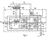
- the hydrostatic piston machine 1 comprises a pump 2 for the parallel conveying of pressure medium into two separate, closed hydraulic circuits.
- the delivery rate of the pump 2 can be changed together by an adjusting device 3 for both hydraulic circuits.
- the adjusting device 3 consists of a cylinder and a control piston 4 arranged therein, which is acted upon in a known manner at opposite mutually oriented piston surfaces in each case a control pressure chamber with a control pressure.
- the two control pressure chambers are connected via a respective control pressure line 6a, 6b with a control pressure control valve 5.
- the first hydraulic circuit is formed from a first working line 7 and a second working line 8.
- the pump 2 promotes either in the first working line 7 or in the second working line 8.
- a promotion in the first working line 7 takes place simultaneously due to the common adjustment of a promotion of pressure medium in a third working line 7 'of the second hydraulic circuit or, in promotion in the second working line 8 of the first hydraulic circuit, in a fourth working line 8 'of the second hydraulic circuit.
- the first hydraulic circuit consisting of the first working line 7 and the second working line 8 is hydraulically independent of the second hydraulic circuit, consisting of its third working line 7 'and its fourth working line 8'.
- the auxiliary pump 9 When starting the pump 2, first the first hydraulic circuit and the second hydraulic circuit is fed by an auxiliary pump 9 with pressure medium.
- the auxiliary pump 9 sucks pressure medium via a suction line 10 from a tank volume 11.
- a filter 12 is arranged in the suction line 10 outside the housing of the hydrostatic piston machine 1, which frees the sucked pressure fluid from impurities.
- a first feed device 13 and a second feed device 14 are provided, wherein the first Feed device 13 is connected to the first working line 7 of the first hydraulic circuit and the second feed device 14 to the second working line 8 of the first hydraulic circuit.
- a third feeder 13 ' is connected to the third working line 7' of the second hydraulic circuit and a fourth feeder 14 'is connected to the fourth working line 8' of the second hydraulic circuit.
- the first to fourth feeders 13, 13 ', 14 and 14' are connected in common with a feed pressure channel 15, in which the auxiliary pump 9 promotes the sucked pressure medium.
- a check valve 17 which, for supplying pressure medium, a flow path from the feed pressure channel 15 in the direction of the respectively connected working line 7, 8, 7 'or 'opens, as long as the pressure in the feed pressure channel 15 is greater than the respective working pressure.
- Parallel to the check valve 17 is a respective high pressure relief valve 18 in the feeders 13, 13 ', 14 and 14' are arranged. When a critical pressure in the respective working line 7, 8, 7 ', or 8' is exceeded, the respective high-pressure relief valve 18 opens in the direction of the feed pressure channel 15.
- the control pressure control valve 5 is designed as a 4/3-way valve, which is continuously adjustable. To set a specific position, the control pressure regulating valve 5 is acted upon by a force acting in the axial direction starting from its neutral position in which it is held by compression springs. This force is generated as a force difference between two proportional magnets 20a and 20b, which act in the same direction with a respective compression spring on a valve piston of the control pressure control valve 5. The respectively adjusted position of the control piston 4 is taken into account in the regulation of the control pressure by a valve sleeve of the control pressure control valve 5 is connected to the actuating piston 4 via a coupling rod 21.
- control pressure control valve 5 is connected to the supply pressure duct 15 via a control pressure supply 16.
- the adjusting device 3 can thus be actuated when starting the pump 2 from the time at which the auxiliary pump 9 has built a pressure in the feed pressure channel 15.
- the adjusting device 3 can thus be operated independently of the funded by the pump 2 in the first hydraulic circuit or second hydraulic circuit pressure medium quantity.
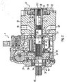
- the auxiliary pump 9 and the pump 2 are driven in the illustrated embodiment by a common drive shaft 22.
- the common drive shaft 22 is supported by a roller bearing 23 at one end of a pump housing 24.
- the common drive shaft 22 is mounted in a sliding bearing 26, which in a Terminal block 25 is arranged, which closes the pump housing 24 at the opposite end.
- the terminal block 25 is a, the terminal block completely penetrating in the axial direction recess 33 is formed, in which on the one hand the sliding bearing 26 is arranged and which is penetrated to the other by the common drive shaft 22.
- the auxiliary pump 9 is inserted into a radial extension of the recess 33.
- the common drive shaft 22 has a toothing 27.1, which is in engagement with the corresponding toothing of the auxiliary pump shaft 28.
- the auxiliary pump shaft 28 is supported in the recess 33 by a first auxiliary pump sliding bearing 34 and by a second auxiliary pump sliding bearing 35 in the auxiliary pump connecting plate 31.
- a gear 29 is arranged, which is in engagement with a ring gear 30.
- the ring gear 30 which is rotatably arranged in the auxiliary pump connection plate 31, also driven by the auxiliary pump shaft 28 and thus ultimately by the common drive shaft 22.
- the suction and the pressure-side connection for the auxiliary pump 9 are formed.
- the auxiliary pump 9 is fixed in the radial extension of the recess 33 of the connection block 25 by a cover 32 which is mounted on the connection block 25.
- connection block 25 In a particularly preferred embodiment of the connection block 25 according to the invention, the suction and the pressure-side connection are formed in the connection block 25, as described below in the detailed description of the connection block 25 according to the invention with reference to FIG Fig. 3 to 8 is explained.
- the inner ring of the roller bearing 23 is fixed in the axial direction on the common drive shaft 22.
- the inner ring rests on the one hand on a collar 36 of the common drive shaft 22 and is held on the other side by a locking ring 37 in this axial position, which is inserted in a groove of the common drive shaft 22.
- the axial position of the roller bearing 23 with respect to the pump housing 24 is determined by a locking ring 38 which is inserted into a circumferential groove of the shaft opening 39.
- a sealing ring 40 and finally a further locking ring 41 is disposed in the shaft opening 39, wherein the locking ring 41 is inserted into a circumferential groove of the shaft opening 39.
- a drive toothing 42 is formed, via which the hydrostatic piston engine is driven by a drive machine, not shown.
- a cylinder drum 43 is arranged, which has a central passage opening 44, which is penetrated by the common drive shaft 22. Via a further drive toothing 45, the cylinder drum 43 is secured against rotation, but slidably connected in the axial direction with the common drive shaft 22, so that a rotational movement of the common drive shaft 22 transmits to the cylinder drum 43.
- a further securing ring 46 is used, on which a first support plate 47 rests.
- the first support disk 47 forms a first spring bearing for a compression spring 48.
- a second spring bearing for the compression spring 48 is formed by a second support plate 49, located on the front side of the other Drive toothing 45 is supported.
- the compression spring 48 thus exerts on the one hand on the common drive shaft 42 and on the other hand on the cylinder drum 43 in each case a force in the opposite axial direction.
- the common drive shaft 22 is loaded so that the outer ring of the roller bearing 23 is supported on the disc 38.
- the compression spring 48 acts on the cylindrical drum 43, which is held with a formed on the end face of the cylindrical drum 43 spherical recess 51 in contact with a control plate 52.
- the control plate 52 in turn bears sealingly against the connection block 25 with the side remote from the cylinder drum 43.
- the cylinder drum 43 is centered.
- the control plate 52 may also be made flat.
- the position of the control plate 52 in the radial direction is determined by the outer circumference of the sliding bearing 26.
- the sliding bearing 26 is used for this purpose only partially in the recess 33 in the terminal block 25.
- cylinder bores 53 are distributed over a common pitch circle introduced, in which piston 54 'are arranged, which are longitudinally displaceable in the cylinder bores 53.
- pistons 54 protrude partially out of the cylinder drum 43.
- a respective sliding shoe 55 is attached to the piston 54, via which the piston 54 is supported on a running surface 56 of a swash plate 57.
- the angle which the running surface 56 of the swashplate 57 encloses with the central axis can be changed.
- the swash plate 57 can be adjusted by the adjusting device 3 in its inclination.
- the swash plate 57 is roller-mounted in the pump housing 24.
- connection block 25 For connecting the hydrostatic piston machine 1 to a first hydraulic circuit and to a second hydraulic circuit, a first connection 58 for a first working power and a second connection 58 'for a second working line are shown schematically in the connection block 25, which in a manner not shown on the Control plate 52 are connected to the cylinder bores 53.
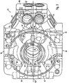
- Fig. 3 shows a perspective view of a terminal block according to the invention 25.
- the terminal block 25 is shown substantially from the side of the control plate 52 from.
- a first working pressure channel 60 and a second working pressure channel 61 are arranged.
- the first working pressure channel 60 and the second working pressure channel 61 are associated with the first hydraulic circuit.
- the second hydraulic circuit, a third working pressure channel 62 and a fourth working pressure channel 63 are assigned.
- the four working pressure channels 60 to 63 connect the suction or pressure-side working lines 7, 7 ', 8 and 8' of the first and second hydraulic circuits to the corresponding control elements of the control plate 52.
- a first connection 64 is formed, to which the first working line 7 of the first hydraulic circuit can be connected.
- a second connection 65 is formed on the end of the second working pressure channel 61 located diametrically opposite the longitudinal axis of the connection block 25.
- a third port 66 and a fourth port 67 are formed on the outside of the port block 25.
- the third terminal 66 and the fourth terminal 67 are disposed on the same side of the terminal block 25.
- the respectively remote from the terminals 64 to 67 ends of the working pressure channels 60 to 63 terminate in a surface of the terminal block 25, at which the control plate 52 is tight.
- the orifices are kidney-shaped.
- the position of the mouths of the first working pressure channel 60 and the second working pressure channel 61 corresponds to the position of a first control kidney and a second control kidney in the control plate 52 and are provided in the drawing by the reference numerals 68 and 69.
- the terminals 64 and 65 are subsequently produced by preferably machining processes to provide sufficient surface quality for sealing engagement with the first and second Ensure work lead 7 and 8.
- the kidney-shaped orifices 68 and 69 are also introduced into the cast blank, e.g. by milling.
- the connections and recesses to be described below, which are located on the outside of the connection block 25, are likewise produced by machining, the channels connected to them each being already produced during the casting of the blank by means of molded parts.
- Control plate 52 further comprises a third control kidney 70 'and a fourth control kidney 71' which extend along a respective portion of another arc of a smaller diameter.
- Corresponding outlets 70 and 71 of the third working pressure channel 62 and the fourth working pressure channel 63 correspond to the position of the third control kidney 70 'and the fourth control kidney 71' in the control plate 52.
- the orifices 68 to 71 of the working pressure channels 60 to 63 are flow-connected to the control kidneys 68 to 71.
- the first working pressure channel 60 is connected via a first connecting channel 72 with a first recess 76.
- the second, third and fourth working pressure ducts 61, 62 and 63 are also connected via a second, third and fourth connecting channel 73, 74 and 75 to a second, third and fourth recess 77, 78 and 79.
- a common feed pressure channel 80 is connected to the first to fourth recesses 76 to 79.
- the first to fourth recesses 76 to 79 are for receiving the in the Fig. 3 Not shown dining facilities 13, 14, 13 'and 14' are provided.
- the feeders 13, 14, 13 'and 14' each include a check valve 17, which opens in the direction of the respective working pressure channel 60 to 63.
- the check valve 17 is open pressure medium flows from the common feed pressure channel 80 in the corresponding working pressure duct 60 to 63, as long as the pressure in the feed pressure channel 80 is higher than in the respective working line 7, 8, 7 'and 8'.
- the pressures in the four working pipes 7, 8, 7 'and 8' can be measured separately via a first to fourth measuring connection.
- a second measuring channel 81 branches off from the second connecting channel 73, which opens a second measuring port 82 on the outer side of the housing.
- the first recess 76 and the second recess 77 provided for receiving the feed devices 13 and 14 of the first hydraulic circuit are arranged in a V-shape and are introduced into the connection block 25 on the side remote from the third connection 66 and the fourth connection 67.
- the third recess 78 and the fourth recess 79 are also arranged in a V-shape with a preferably identical opening angle.
- the third recess 78 and the fourth recess 79 assigned to the second hydraulic circuit are arranged offset in the axial direction with respect to the longitudinal axis to the first recess 76 and the second recess 77. Accordingly, the feed pressure channel 80 extends in the axial direction.
- a crizoventilausnaturalung 83 and a Niederbuchventilausnaturalung 84 are further arranged.
- the Regelventilausnaturalung 83 can in Fig. 1 shown control valve 120 used, preferably screwed.
- the crizventilausnaturalung 83 and the Niederbuchventilaus Principleung 84 are oriented parallel to the longitudinal axis introduced into the extension 85 and are each also with the feed pressure duct 80 via a connection channel 80 'in connection.
- the crizoventilausnaturalung 83 is provided for receiving a cartridge which generates a speed-dependent control pressure depending on the drive speed of the pump.
- the pressure relief valve 19 is used.
- auxiliary pressure channel 86 connects an auxiliary pressure output of the auxiliary pump 9 with the feed pressure channel 80.
- the auxiliary pressure channel 86 is laterally led out through the extension 85 from the terminal block 25, wherein the opening 87 is closed during operation with a stopper, if it is provided to operate in the terminal block 25, an auxiliary pump 9. If an external auxiliary pressure source is used, its auxiliary pressure supply line is connected to the auxiliary pressure channel 86.
- the arrangement of the first to fourth recesses 76 to 79, and the Stelltikventilaus principleung 83 and the Niederchristventilaus principleung 84 is approximately symmetrical with respect to a plane passing through a first divider 101 and a second divider 102 symmetry plane 103rd
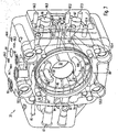
- Fig. 4 is a plan view of the control plate 52 facing side of the terminal block 25 is shown. It is only the first recess 76 and the second recess 77 and the first connection channel 72 and the second connection channel 73 can be seen.
- the equivalent recesses or connection channels for the second hydraulic circuit are in the illustration of Fig. 4 not to be seen, since they are hidden, offset in the axial direction are arranged.
- the control valve recess 83 intersects with the auxiliary pressure channel 86, so that the control valve inserted into the Regelventilaus Principleung 83 is supplied via the auxiliary pressure channel 86 of the feed pressure generated by the auxiliary pump 9.
- a suction connection 88 can be seen, which is connected to a suction kidney of the auxiliary pump 9.
- a suction connection 88 is connected to a suction kidney of the auxiliary pump 9.
- slide bearing 26 with pressure medium for lubrication
- a leakage oil hole 90 penetrates the control valve recess 83 and opens into a discharge channel 91, which is introduced from the outside by drilling into the extension 85 and is connected to the low-pressure valve recess 84. Via the drainage channel 91, both the leakage oil of the control valve and the pressure fluid flowing out through the relief when the pressure-limiting valve 19 is opened are discharged into the housing volume.
- first working pressure channel 60 and the second working pressure channel 61 widen in the direction of the orifices 68 and 69, and the first and second connecting channels 72 and 73 open in this widened region from the side of the extension 85.
- a side view of the side of the first terminal 64 is shown. Good to see the axially offset arrangement of the first recess 76 and the second. Recess 78 and the course of the first connection channel 72 and the third connection channel 74.
- a first measuring port 97 is provided, which via a first connection hole 92nd is connected to the first working pressure channel 60.
- a third measuring connection 93 is provided for measuring the pressure prevailing in the third working line 7 '.
- the third measuring connection 93 is formed on the end of a measuring bore arranged on the outside of the connection block 25, which is in the third Connecting channel 74 opens and is connected to this.
- a system of intersecting holes 104 is formed, which together form a control channel system.
- the holes on the outside of the terminal block 25 are closed with plugs.
- Fig. 6 shows a side view of the in the representation of Fig. 5 side opposite.
- the second measuring port 81 is shown, which is connected via a measuring bore directly to the second connecting channel 73.
- a fourth measuring connection 94 is shown, which is likewise connected directly to the fourth connecting channel 75 via a measuring bore.
- an auxiliary pressure port 95 is formed, which is connected via a bore 95 'to the feed pressure channel 80.
- about the auxiliary pressure port 95 z. B. more hydraulic consumers are supplied with the feed pressure of the auxiliary pump 9.
- All fastening bores 105 have an enlargement of the diameter at the side facing the auxiliary pump 9, the sinking of the fastening screws, which are screwed into a provided in the housing, not shown, the housing of the piston engine allow.
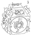
- Fig. 7 shows the terminal block 25 from the side on which the auxiliary pump 9 is arranged.
- a suction kidney 106 and a Hilfstikniere 107 are introduced in the recessed area, which accommodates the auxiliary pump 9, a suction kidney 106 and a Hilfstikniere 107 are introduced.
- the Hilfstikniere 107 is connected via the auxiliary pressure channel 86 to the feed pressure channel 80, as with reference to Fig. 3 has already been explained.
- the suction kidney 106 is connected via a suction channel 108 to the terminal 88, to which in turn the suction line 1 is connected.
- FIG Fig. 8 A perspective view of the terminal block is shown in FIG Fig. 8 shown.
- the feeders 13, 13 ', 14 and 14' which are designed as cartridges, inserted into the corresponding recesses 76 to 79.
- the pressure limiting valve 19 is inserted into the Niedertownventilaus Principleung 84.
- the terminal block 25 is a preassembled unit in which all the components are already present, which are required on the one hand for feeding the two hydraulic circuits when starting the piston engine and on the other hand an increase in the pressure in the working lines over a critical value for each working line 7, 8, 7 'and 8' individually prevent.
- the measuring connections are closed with plugs 109. From the mounting holes 105 protrude in the direction of the hydrostatic piston engine screws 110 and introduced into corresponding recesses in the front side dowel pins 111 for the exact definition of the position of the terminal block 25 with respect to the hydrostatic piston engine out.
- the arrangement described not only allows a high degree of integration with respect to the functionality of the terminal block 25, but due to the guidance of the individual channels, as well as the arrangement of the corresponding terminals on the outside of the terminal block 25, to keep the overall length of the terminal block 25 small.
- all valves, where maintenance may possibly be required are arranged on only one side of the terminal block 25. This results in a simplified maintenance, since in the assembled state, the valves are all accessible from the same side.
- no lines have to be dismantled since all the necessary connections are formed as channels in the interior of the connection block 25 and the valves used are used only in recesses provided for this purpose as cartridges.
Landscapes
- Engineering & Computer Science (AREA)
- Mechanical Engineering (AREA)
- General Engineering & Computer Science (AREA)
- Reciprocating Pumps (AREA)
Abstract
Claims (8)
- Bloc de raccordement pour une machine hydrostatique à piston, qui est prévue pour fonctionner simultanément dans un premier circuit hydraulique et dans un deuxième circuit hydraulique, l'ensemble présentant les particularités suivantes :dans le bloc de raccordement sont réalisés un premier canal de pression de travail (60) et un deuxième canal de pression de travail (61), par l'intermédiaire desquels une première respectivement une deuxième conduite de travail (7, 8) du premier circuit hydraulique peuvent être reliées à une première respectivement une deuxième lumière de commande réniforme (68', 69') d'un plateau de commande (52) de la machine hydrostatique à piston, etdans le bloc de raccordement (25) sont réalisés un troisième canal de pression de travail (62) et un quatrième canal de pression de travail (63), par l'intermédiaire desquels une troisième respectivement une quatrième conduite de travail (7', 8') du deuxième circuit hydraulique peuvent être reliées à une troisième respectivement une quatrième lumière de commande réniforme (70', 71') du plateau de commande (52) de la machine hydrostatique à piston,dans le bloc de raccordement (25) est prévu un canal de pression d'alimentation (80) commun,et le canal de pression d'alimentation (80) commun peut être relié au premier et jusqu'au quatrième canal de pression de travail (60, 61, 62, 63), respectivement par l'intermédiaire d'un dispositif d'alimentation séparé (13, 13', 14, 14'),caractériséen ce que les canaux de pression de travail (60, 61, 62, 63) débouchent de manière réniforme, à leurs extrémités opposées à celles dirigées vers les conduites de travail (7, 8, 7', 8'), dans une surface frontale du bloc de raccordement (25), qui est orientée vers le plateau de commande (52).
- Bloc de raccordement selon la revendication 1, caractérisé en ce que les dispositifs d'alimentation (13, 13', 14, 14') peuvent être insérés dans des évidements (76, 77, 78, 79) du bloc de raccordement (25).
- Bloc de raccordement selon la revendication 1 ou la revendication 2,
caractérisé en ce que dans chacun des quatre dispositifs d'alimentation (13, 13', 14, 14') est prévue une soupape de limitation de haute pression (18), par l'intermédiaire de laquelle, en cas de dépassement d'une valeur de pression limite, la pression dans la conduite de travail correspondante (7, 8, 7', 8') reliée au premier et jusqu'au quatrième canal de pression de travail (60, 61, 62, 63), est délestée dans le canal d'alimentation (80) commun du bloc de raccordement (25). - Bloc de raccordement selon l'une des revendications 1 à 3,
caractérisé en ce qu'au moins le premier et le deuxième canal de pression de travail (60, 61) ou le troisième et le quatrième canal de pression de travail (62, 63) débouchent sur un côté du bloc de raccordement (25). - Bloc de raccordement selon l'une des revendications 1 à 4,
caractérisé en ce que les orifices de sortie (68, 69) réniformes du premier et du deuxième canal de pression de travail (60, 61) s'étendent le long d'un premier cercle primitif sur le côté frontal du bloc de raccordement (25). - Bloc de raccordement selon la revendication 4 ou la revendication 5,
caractérisé en ce que les orifices de sortie (70, 71) réniformes du troisième et du quatrième canal de pression de travail (62, 63) s'étendent le long d'un deuxième cercle primitif sur le côté frontal du bloc de raccordement (25). - Bloc de raccordement selon l'une des revendications 1 à 6,
caractérisé en ce que sur le côté du bloc de raccordement (25), qui est opposé à celui dirigé vers la machine hydrostatique à piston, une pompe auxiliaire (9) peut être insérée dans le bloc de raccordement et refoule dans le canal de pression d'alimentation (80). - Bloc de raccordement selon l'une des revendications 1 à 7,
caractérisé en ce que tous les dispositifs d'alimentation (13, 13', 14, 14') sont agencés sur un côté commun du bloc de raccordement.
Applications Claiming Priority (3)
| Application Number | Priority Date | Filing Date | Title |
|---|---|---|---|
| DE10349599A DE10349599B3 (de) | 2003-10-24 | 2003-10-24 | Anschlussblock für eine hydrostatische Kolbenmaschine |
| DE10349599 | 2003-10-24 | ||
| PCT/EP2004/011357 WO2005042973A1 (fr) | 2003-10-24 | 2004-10-11 | Bloc de raccordement d'une machine a piston hydrostatique |
Publications (2)
| Publication Number | Publication Date |
|---|---|
| EP1565652A1 EP1565652A1 (fr) | 2005-08-24 |
| EP1565652B1 true EP1565652B1 (fr) | 2012-04-11 |
Family
ID=34529752
Family Applications (1)
| Application Number | Title | Priority Date | Filing Date |
|---|---|---|---|
| EP04790264A Expired - Lifetime EP1565652B1 (fr) | 2003-10-24 | 2004-10-11 | Bloc de raccordement d'une machine a piston hydrostatique |
Country Status (4)
| Country | Link |
|---|---|
| US (1) | US7437873B2 (fr) |
| EP (1) | EP1565652B1 (fr) |
| DE (1) | DE10349599B3 (fr) |
| WO (1) | WO2005042973A1 (fr) |
Cited By (3)
| Publication number | Priority date | Publication date | Assignee | Title |
|---|---|---|---|---|
| DE102020215991A1 (de) | 2020-12-16 | 2022-06-23 | Robert Bosch Gesellschaft mit beschränkter Haftung | Anschlussblock |
| DE102022200038A1 (de) | 2022-01-05 | 2023-07-06 | Robert Bosch Gesellschaft mit beschränkter Haftung | Anschlussblock |
| DE102023207507A1 (de) * | 2023-08-04 | 2025-02-06 | Robert Bosch Gesellschaft mit beschränkter Haftung | Zentrierung der Gehäuseteile einer Axialkolbenmaschine |
Families Citing this family (8)
| Publication number | Priority date | Publication date | Assignee | Title |
|---|---|---|---|---|
| DE102009037733B4 (de) | 2009-08-17 | 2021-12-09 | Robert Bosch Gmbh | Regelventilanordnung und Verstellpumpe |
| DE102010048068B4 (de) | 2010-04-16 | 2022-11-10 | Robert Bosch Gmbh | Ventilanordnung |
| DE102011013779A1 (de) * | 2010-04-16 | 2011-10-20 | Robert Bosch Gmbh | Anschlussplatte für eine hydrostatische Kolbenmaschine |
| DE102012016068B4 (de) * | 2012-08-14 | 2023-07-20 | Robert Bosch Gmbh | Anschlussvorrichtung für hydrostatische Maschine und hydrostatische Maschine |
| DE102013208453A1 (de) | 2013-05-08 | 2014-11-13 | Robert Bosch Gmbh | Hydrostatische Doppelpumpe, insbesondere Axialkolbendoppelpumpe in Schrägscheibenbauweise |
| EP3137768B1 (fr) * | 2014-04-30 | 2020-10-14 | Anthony George Hurter | Appareil et procédé de purification de fioul usagé à l'eau supercritique |
| CN104533741A (zh) * | 2014-12-30 | 2015-04-22 | 南京萨伯工业设计研究院有限公司 | 伺服控制变量柱塞泵及其控制方法 |
| CN108180130B (zh) * | 2018-03-09 | 2024-02-06 | 江苏徐工工程机械研究院有限公司 | 变量伺服阀、液压系统及变量泵 |
Family Cites Families (10)
| Publication number | Priority date | Publication date | Assignee | Title |
|---|---|---|---|---|
| US2445281A (en) * | 1945-10-04 | 1948-07-13 | Charles H Rystrom | Hydraulic pump |
| DE3026765A1 (de) * | 1980-07-15 | 1982-02-11 | Linde Ag, 6200 Wiesbaden | Axialkolbenpumpe fuer zwei foerderstroeme |
| DE3413867C2 (de) * | 1983-04-13 | 1995-04-06 | Linde Ag | Axialkolbenpumpe für zwei Förderströme |
| DE3333812C2 (de) * | 1983-09-19 | 1986-08-07 | Hydromatik GmbH, 7915 Elchingen | Schwenktrommel-Axialkolbenmaschine |
| DE3723988A1 (de) * | 1987-07-20 | 1989-02-09 | Hydromatik Gmbh | Axialkolbenmaschine, deren kolben als stufenkolben ausgebildet sind |
| DE4225380B4 (de) * | 1992-07-31 | 2004-07-15 | Linde Ag | Hydrostatisches Aggregat mit einer Hauptpumpe und einer Nebenpumpe |
| US5495713A (en) * | 1994-11-22 | 1996-03-05 | Leker; Richard E. | Hydrostatic differential transmission |
| DE19536997C1 (de) | 1995-10-04 | 1997-02-20 | Brueninghaus Hydromatik Gmbh | Doppelpumpe mit Ladepumpe |
| JP2000087904A (ja) * | 1998-09-14 | 2000-03-28 | Komatsu Ltd | 圧油供給装置 |
| US6425244B1 (en) | 1999-10-18 | 2002-07-30 | Kanzaki Kokyukoki Mfg. Co., Ltd. | Pump unit |
-
2003
- 2003-10-24 DE DE10349599A patent/DE10349599B3/de not_active Expired - Fee Related
-
2004
- 2004-10-11 EP EP04790264A patent/EP1565652B1/fr not_active Expired - Lifetime
- 2004-10-11 WO PCT/EP2004/011357 patent/WO2005042973A1/fr not_active Ceased
- 2004-10-11 US US10/577,004 patent/US7437873B2/en not_active Expired - Fee Related
Cited By (4)
| Publication number | Priority date | Publication date | Assignee | Title |
|---|---|---|---|---|
| DE102020215991A1 (de) | 2020-12-16 | 2022-06-23 | Robert Bosch Gesellschaft mit beschränkter Haftung | Anschlussblock |
| DE102022200038A1 (de) | 2022-01-05 | 2023-07-06 | Robert Bosch Gesellschaft mit beschränkter Haftung | Anschlussblock |
| US12609334B2 (en) | 2022-01-05 | 2026-04-21 | Robert Bosch Gmbh | Connection block |
| DE102023207507A1 (de) * | 2023-08-04 | 2025-02-06 | Robert Bosch Gesellschaft mit beschränkter Haftung | Zentrierung der Gehäuseteile einer Axialkolbenmaschine |
Also Published As
| Publication number | Publication date |
|---|---|
| US7437873B2 (en) | 2008-10-21 |
| US20070130930A1 (en) | 2007-06-14 |
| WO2005042973A1 (fr) | 2005-05-12 |
| DE10349599B3 (de) | 2005-07-07 |
| EP1565652A1 (fr) | 2005-08-24 |
Similar Documents
| Publication | Publication Date | Title |
|---|---|---|
| EP2092192B1 (fr) | Machine à piston axial hydrostatique | |
| DE2821593C2 (de) | Zweistufenpumpe | |
| DE2848208C2 (de) | Vorgesteuertes Druckbegrenzungsventil mit Einspeisefunktion | |
| DE102017121882B3 (de) | Schraubenspindelpumpe | |
| EP1212517B1 (fr) | Dispositif de reglage d'un arbre a cames destine a des moteurs a combustion interne | |
| EP1565652B1 (fr) | Bloc de raccordement d'une machine a piston hydrostatique | |
| DE4428667C2 (de) | Kombiniertes Stromregel- und Druckregelventil für eine Pumpe und mit patronenförmigem Ventilgehäuse | |
| DE102022200140A1 (de) | Axialkolbenmaschine mit zumindest teilweise spanend hergestellten Vorkompressionsräumen | |
| DE102004061861A1 (de) | Druckabschneidungsventileinheit und damit versehener hydraulischer Kreislauf | |
| DE3516747C2 (de) | Steuereinrichtung für ein hydrostatisches Getriebe | |
| DE3117743C2 (de) | Ölpumpe | |
| EP0509077B1 (fr) | Pompe a pistons, notamment pompe a pistons radiaux | |
| DE102018216831A1 (de) | Regelvorrichtung für Pumpendruck und -volumenstrom mit konzentrischen Steuerschiebern | |
| EP1278960A1 (fr) | Machine hydrostatique | |
| DE10347085B3 (de) | Hydrostatische Kolbenmaschine mit zwei hydraulischen Kreisläufen | |
| DE3242983A1 (de) | Regelbare fluegelzellenpumpe | |
| DE102015223037A1 (de) | Vibrationsantrieb mit hydraulischer Pulserzeugungsvorrichtung | |
| DE102007032102A1 (de) | Pumpeneinheit mit Hauptpumpe und Hilfspumpe | |
| DE1293599B (de) | Zahnradpumpe | |
| EP1694965B1 (fr) | Dispositif de regulation de puissance totale | |
| DE102021205558A1 (de) | Hydromaschine mit Speise- und Hauptpumpe und flexiblen Tankanschlüssen | |
| DE2231003A1 (de) | Pumpe mit veraenderbarer verdraengung und druckausgleichssteuerung | |
| DE3627375A1 (de) | Verstellvorrichtung fuer einen axialkolben-schraegachsenhydrostaten | |
| DE102014202411A1 (de) | Elektrisch angesteuertes Druckregelventil für eine verstellbare hydrostatische Pumpe und eine verstellbare hydrostatische Pumpe mit einem Druckregelventil | |
| DE102009012560B4 (de) | Ventilvorrichtung für eine Regelungsvorrichtung |
Legal Events
| Date | Code | Title | Description |
|---|---|---|---|
| PUAI | Public reference made under article 153(3) epc to a published international application that has entered the european phase |
Free format text: ORIGINAL CODE: 0009012 |
|
| 17P | Request for examination filed |
Effective date: 20050613 |
|
| AK | Designated contracting states |
Kind code of ref document: A1 Designated state(s): AT BE BG CH CY CZ DE DK EE ES FI FR GB GR HU IE IT LI LU MC NL PL PT RO SE SI SK TR |
|
| AX | Request for extension of the european patent |
Extension state: AL HR LT LV MK |
|
| DAX | Request for extension of the european patent (deleted) | ||
| RBV | Designated contracting states (corrected) |
Designated state(s): DE FR GB IT SE |
|
| 17Q | First examination report despatched |
Effective date: 20101026 |
|
| RAP1 | Party data changed (applicant data changed or rights of an application transferred) |
Owner name: BOSCH REXROTH AG |
|
| GRAP | Despatch of communication of intention to grant a patent |
Free format text: ORIGINAL CODE: EPIDOSNIGR1 |
|
| GRAS | Grant fee paid |
Free format text: ORIGINAL CODE: EPIDOSNIGR3 |
|
| GRAA | (expected) grant |
Free format text: ORIGINAL CODE: 0009210 |
|
| AK | Designated contracting states |
Kind code of ref document: B1 Designated state(s): DE FR GB IT SE |
|
| REG | Reference to a national code |
Ref country code: GB Ref legal event code: FG4D Free format text: NOT ENGLISH |
|
| REG | Reference to a national code |
Ref country code: DE Ref legal event code: R096 Ref document number: 502004013439 Country of ref document: DE Effective date: 20120606 |
|
| PG25 | Lapsed in a contracting state [announced via postgrant information from national office to epo] |
Ref country code: SE Free format text: LAPSE BECAUSE OF FAILURE TO SUBMIT A TRANSLATION OF THE DESCRIPTION OR TO PAY THE FEE WITHIN THE PRESCRIBED TIME-LIMIT Effective date: 20120411 |
|
| PGFP | Annual fee paid to national office [announced via postgrant information from national office to epo] |
Ref country code: FR Payment date: 20121113 Year of fee payment: 9 |
|
| PLBE | No opposition filed within time limit |
Free format text: ORIGINAL CODE: 0009261 |
|
| STAA | Information on the status of an ep patent application or granted ep patent |
Free format text: STATUS: NO OPPOSITION FILED WITHIN TIME LIMIT |
|
| PGFP | Annual fee paid to national office [announced via postgrant information from national office to epo] |
Ref country code: IT Payment date: 20121025 Year of fee payment: 9 Ref country code: GB Payment date: 20121023 Year of fee payment: 9 |
|
| 26N | No opposition filed |
Effective date: 20130114 |
|
| REG | Reference to a national code |
Ref country code: DE Ref legal event code: R097 Ref document number: 502004013439 Country of ref document: DE Effective date: 20130114 |
|
| GBPC | Gb: european patent ceased through non-payment of renewal fee |
Effective date: 20131011 |
|
| PG25 | Lapsed in a contracting state [announced via postgrant information from national office to epo] |
Ref country code: GB Free format text: LAPSE BECAUSE OF NON-PAYMENT OF DUE FEES Effective date: 20131011 |
|
| REG | Reference to a national code |
Ref country code: FR Ref legal event code: ST Effective date: 20140630 |
|
| PG25 | Lapsed in a contracting state [announced via postgrant information from national office to epo] |
Ref country code: IT Free format text: LAPSE BECAUSE OF NON-PAYMENT OF DUE FEES Effective date: 20131011 Ref country code: FR Free format text: LAPSE BECAUSE OF NON-PAYMENT OF DUE FEES Effective date: 20131031 |
|
| PGFP | Annual fee paid to national office [announced via postgrant information from national office to epo] |
Ref country code: DE Payment date: 20141208 Year of fee payment: 11 |
|
| REG | Reference to a national code |
Ref country code: DE Ref legal event code: R119 Ref document number: 502004013439 Country of ref document: DE |
|
| PG25 | Lapsed in a contracting state [announced via postgrant information from national office to epo] |
Ref country code: DE Free format text: LAPSE BECAUSE OF NON-PAYMENT OF DUE FEES Effective date: 20160503 |