EP1564446B1 - Verfahren und Vorrichtung zum Steuern eines Gangwechsels in einem Parallelschaltgetriebe eines Fahrzeuges - Google Patents
Verfahren und Vorrichtung zum Steuern eines Gangwechsels in einem Parallelschaltgetriebe eines Fahrzeuges Download PDFInfo
- Publication number
- EP1564446B1 EP1564446B1 EP05000775A EP05000775A EP1564446B1 EP 1564446 B1 EP1564446 B1 EP 1564446B1 EP 05000775 A EP05000775 A EP 05000775A EP 05000775 A EP05000775 A EP 05000775A EP 1564446 B1 EP1564446 B1 EP 1564446B1
- Authority
- EP
- European Patent Office
- Prior art keywords
- clutch
- transmission
- transmission ratio
- torque
- slip
- Prior art date
- Legal status (The legal status is an assumption and is not a legal conclusion. Google has not performed a legal analysis and makes no representation as to the accuracy of the status listed.)
- Expired - Lifetime
Links
- 230000008859 change Effects 0.000 title claims abstract description 59
- 230000005540 biological transmission Effects 0.000 title claims description 72
- 238000000034 method Methods 0.000 title claims description 18
- 230000001276 controlling effect Effects 0.000 claims description 12
- 230000001133 acceleration Effects 0.000 claims description 10
- 230000001105 regulatory effect Effects 0.000 claims description 7
- 230000004913 activation Effects 0.000 claims 5
- 230000007363 regulatory process Effects 0.000 claims 1
- 230000008878 coupling Effects 0.000 description 7
- 238000010168 coupling process Methods 0.000 description 7
- 238000005859 coupling reaction Methods 0.000 description 7
- 230000007423 decrease Effects 0.000 description 4
- 238000010586 diagram Methods 0.000 description 4
- 230000008901 benefit Effects 0.000 description 2
- 230000033228 biological regulation Effects 0.000 description 2
- 230000009467 reduction Effects 0.000 description 2
- 230000007704 transition Effects 0.000 description 2
- 230000003213 activating effect Effects 0.000 description 1
- 230000000386 athletic effect Effects 0.000 description 1
- 238000002485 combustion reaction Methods 0.000 description 1
- 238000004891 communication Methods 0.000 description 1
- 238000001514 detection method Methods 0.000 description 1
- 230000006870 function Effects 0.000 description 1
- 230000015654 memory Effects 0.000 description 1
- 230000001360 synchronised effect Effects 0.000 description 1
- 230000001960 triggered effect Effects 0.000 description 1
Images


Classifications
-
- F—MECHANICAL ENGINEERING; LIGHTING; HEATING; WEAPONS; BLASTING
- F16—ENGINEERING ELEMENTS AND UNITS; GENERAL MEASURES FOR PRODUCING AND MAINTAINING EFFECTIVE FUNCTIONING OF MACHINES OR INSTALLATIONS; THERMAL INSULATION IN GENERAL
- F16H—GEARING
- F16H61/00—Control functions within control units of change-speed- or reversing-gearings for conveying rotary motion ; Control of exclusively fluid gearing, friction gearing, gearings with endless flexible members or other particular types of gearing
- F16H61/04—Smoothing ratio shift
- F16H61/0437—Smoothing ratio shift by using electrical signals
-
- E—FIXED CONSTRUCTIONS
- E03—WATER SUPPLY; SEWERAGE
- E03C—DOMESTIC PLUMBING INSTALLATIONS FOR FRESH WATER OR WASTE WATER; SINKS
- E03C1/00—Domestic plumbing installations for fresh water or waste water; Sinks
- E03C1/12—Plumbing installations for waste water; Basins or fountains connected thereto; Sinks
- E03C1/28—Odour seals
- E03C1/284—Odour seals having U-shaped trap
-
- F—MECHANICAL ENGINEERING; LIGHTING; HEATING; WEAPONS; BLASTING
- F16—ENGINEERING ELEMENTS AND UNITS; GENERAL MEASURES FOR PRODUCING AND MAINTAINING EFFECTIVE FUNCTIONING OF MACHINES OR INSTALLATIONS; THERMAL INSULATION IN GENERAL
- F16H—GEARING
- F16H61/00—Control functions within control units of change-speed- or reversing-gearings for conveying rotary motion ; Control of exclusively fluid gearing, friction gearing, gearings with endless flexible members or other particular types of gearing
- F16H61/04—Smoothing ratio shift
- F16H2061/0462—Smoothing ratio shift by controlling slip rate during gear shift transition
-
- F—MECHANICAL ENGINEERING; LIGHTING; HEATING; WEAPONS; BLASTING
- F16—ENGINEERING ELEMENTS AND UNITS; GENERAL MEASURES FOR PRODUCING AND MAINTAINING EFFECTIVE FUNCTIONING OF MACHINES OR INSTALLATIONS; THERMAL INSULATION IN GENERAL
- F16H—GEARING
- F16H2306/00—Shifting
- F16H2306/40—Shifting activities
- F16H2306/44—Removing torque from current gears
-
- F—MECHANICAL ENGINEERING; LIGHTING; HEATING; WEAPONS; BLASTING
- F16—ENGINEERING ELEMENTS AND UNITS; GENERAL MEASURES FOR PRODUCING AND MAINTAINING EFFECTIVE FUNCTIONING OF MACHINES OR INSTALLATIONS; THERMAL INSULATION IN GENERAL
- F16H—GEARING
- F16H2306/00—Shifting
- F16H2306/40—Shifting activities
- F16H2306/52—Applying torque to new gears
-
- F—MECHANICAL ENGINEERING; LIGHTING; HEATING; WEAPONS; BLASTING
- F16—ENGINEERING ELEMENTS AND UNITS; GENERAL MEASURES FOR PRODUCING AND MAINTAINING EFFECTIVE FUNCTIONING OF MACHINES OR INSTALLATIONS; THERMAL INSULATION IN GENERAL
- F16H—GEARING
- F16H61/00—Control functions within control units of change-speed- or reversing-gearings for conveying rotary motion ; Control of exclusively fluid gearing, friction gearing, gearings with endless flexible members or other particular types of gearing
- F16H61/68—Control functions within control units of change-speed- or reversing-gearings for conveying rotary motion ; Control of exclusively fluid gearing, friction gearing, gearings with endless flexible members or other particular types of gearing specially adapted for stepped gearings
- F16H61/684—Control functions within control units of change-speed- or reversing-gearings for conveying rotary motion ; Control of exclusively fluid gearing, friction gearing, gearings with endless flexible members or other particular types of gearing specially adapted for stepped gearings without interruption of drive
- F16H61/688—Control functions within control units of change-speed- or reversing-gearings for conveying rotary motion ; Control of exclusively fluid gearing, friction gearing, gearings with endless flexible members or other particular types of gearing specially adapted for stepped gearings without interruption of drive with two inputs, e.g. selection of one of two torque-flow paths by clutches
-
- F—MECHANICAL ENGINEERING; LIGHTING; HEATING; WEAPONS; BLASTING
- F16—ENGINEERING ELEMENTS AND UNITS; GENERAL MEASURES FOR PRODUCING AND MAINTAINING EFFECTIVE FUNCTIONING OF MACHINES OR INSTALLATIONS; THERMAL INSULATION IN GENERAL
- F16H—GEARING
- F16H63/00—Control outputs from the control unit to change-speed- or reversing-gearings for conveying rotary motion or to other devices than the final output mechanism
- F16H63/40—Control outputs from the control unit to change-speed- or reversing-gearings for conveying rotary motion or to other devices than the final output mechanism comprising signals other than signals for actuating the final output mechanisms
- F16H63/50—Signals to an engine or motor
Definitions
- the invention relates to a method and a device for controlling a gear change, in particular a traction upshift, in a parallel transmission of a vehicle.
- Fig. 5 shows the drive train of a conventional vehicle.
- a drive motor 2, 10 is connected via a coupling device 12 to a transmission 14, the output shaft 16 is connected in the illustrated example via a propeller shaft 18 and a differential 20 with the rear wheels 22 of a vehicle.
- a clutch actuator 24 is provided for actuating the clutch device 12.
- actuators 26 and 28 are provided.
- the actuators 24, 26, 28 are controlled by an electronic control device 30 with a microprocessor and associated memories. Inputs of the electronic control device 30 are connected to positioners contained in the actuators and speed sensors 32 and 34 for detecting, for example, a rotational speed of a gear shaft and the rotational speed of the propeller shaft 34 and the output shaft 16. Further, an input of the controller 30 is connected to a position sensor 36 of a selector lever 38 for activating various programs of the controller 30.
- an engine control unit 40 To control the drive motor 10 is an engine control unit 40, whose inputs with a position sensor 42 for detecting the position of an accelerator pedal, a speed sensor 46 for detecting the rotational speed of the crankshaft of the internal combustion engine, a temperature sensor 48 for detecting an engine temperature, sensors 50 for detecting further operating parameters of Motors and a position sensor for detecting the position of an actuator 52 for a load actuator 54 of the drive motor 10 are connected. Further, sensors 54 for detecting the rotational speeds of the front wheels 56 and the rear wheels 22 may be provided, which are connected to the engine control unit 40.
- the engine control unit 40 is connected to the Transmission control device 30 via a data line, such as a CAN-BUS 58, connected, via which a data communication.
- a data line such as a CAN-BUS 58
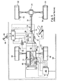
- FIG. 6 schematically shows the structure of the coupling device 12 and the transmission 14.
- An output shaft 58 of the drive motor 10 is rotatably connected to two parallel transmission branches 60 and 62, which are rotatably connected respectively via a gear unit 64 and 66 to the output shaft 16.
- the gear units 64 and 66 may be conventional transmissions whose gears are rotatably connected in a conventional manner via an actuator 68 and 70, respectively.
- the clutches K1 and K2 can be actuated by means of actuators 24 1 and 24 2 .
- Fig. 7 shows the structure of a Doppelkupplungs- or parallel transmission, which has a total of three shafts, namely two input shafts 72 and 74, which can be rotatably connected via different sets of wheels with one of the common output shaft 16.
- the wheelsets are in constant contact with each other.
- the wheels of the input shafts 72 and 74 can be synchronized in a conventional manner by means of axially displaceable on the shafts coupling members 76 with the shafts and brought into rotationally fixed engagement.
- an actuator 78 is provided with a selector member 80 and a switching member 82, wherein the selector, for example, from the actuator 26 (FIGS. Fig.
- the clutches K1 and K2 are on the input side in rotationally fixed engagement with the output shaft 58 of the drive motor.
- the clutches K1 and K2 are from the clutch actuators 24 1 and 24 2 ( Fig. 6 ).
- one of the gears of the transmission branch 62 can be switched with the clutch K2 open, so that by merely opening the clutch K1 and simultaneous closing of the clutch K2 a tensile force free translation change can be made from a gear of the transmission branch 60 to a gear of the transmission branch 62.
- This gear or gear ratio should be as comfortable as possible for the driver of a vehicle, depending on the position of the selector lever 38 in the control device 30th different programs can be activated, according to which the gear change as quickly as possible athletic, as soft and comfortable or otherwise optimized.
- the actuation of the clutches K1 and K2 and the load actuator of the drive motor 10 thus takes place according to programs that are stored, for example, in the controller 30, from where via the bus 58 and the controller 40 and the actuator 52 of the load actuator 53 can be actuated.
- the transmission-side half of the new clutch rotates with the speed of the transmission input shaft plus the slip speed, but the transmission-side half of the new clutch rotates at the speed of the transmission input shaft, is then reduced by a subsequent lowering of the engine torque below the clutch torque of the new clutch pulled down the engine speed to the speed of the newly effective transmission input shaft.
- Braking the engine adds additional torque derived from the energy stored in the flywheel of the engine and acting on the transmission output shaft via the transmission input shaft.
- the reduction of the engine torque corresponds to the torque contribution due to the deceleration of the engine, so that no additional torque is brought to the transmission output shaft by the deceleration of the engine.
- the new clutch is now fully closed and the engine torque is returned to its original value.
- From the DE 103 08 700 A1 is known to zoom at a traction-free ratio change of a parallel shift or dual-clutch transmission, the initially torque-transmitting clutch to its slip limit and to increase the engine torque for a short time, so that the torque-transmitting clutch slips with a reserve and the new clutch does not adhere to the transition from the "old" clutch to the "new” clutch.
- the DE 199 39 334 A1 is disclosed as the closest prior art and discloses the features of the preamble of claim 1. It discloses a dual-clutch transmission and method of shifting the dual-clutch transmission without interruption of traction. The switching operations are carried out by controlling and / or regulating the clutches and the drive motor.
- the invention has for its object to provide a method and an apparatus for its implementation, with which or a gear change a parallel shift transmission, in particular a traction upshift, under all conditions can be made as comfortable as possible.
- an implementation of the method according to the invention is such that the torque of the clutch transmitting the old transmission is continuously changed from about zero to a predetermined value during the gear ratio change to approximately zero and the torque of the clutch transmitting the new gear ratio is continuously changed.
- the load of the drive motor is advantageously precontrolled in accordance with the sum of the instantaneous torques that can be transmitted by the clutches.
- the load of the drive motor is advantageously controlled by means of a D-controller, to which the time derivative of the actual slip is supplied as an input variable.
- the load of the drive motor for keeping constant the slip of the clutches is alternatively or additionally controlled by means of a P-controller, which is fed as an input variable, the difference from the instantaneous slip and slip at the beginning of the ratio change.
- the clutch actuator 24 contains two actuators which can be controlled independently of one another by the control device 30 in accordance therewith and with which the two clutches K1 and K2 (FIG. Fig. 5 and 6 ) are independently operable in such a way that at each clutch a defined clutch torque is transferable.
- the slip of the clutches can be measured via their input speed (detected by the speed sensor 46) and the speeds of the output shafts 72 and 74 (FIG. Fig. 6 ), detected by the sensors 32, or from the rotational speed of the output shaft 16 (detected by the sensor 34) and the respective effective gears (known from the control device 30) are determined.
- the clutch of the old gear is opened and the clutch of the target gear (new clutch) is closed at a certain moment.
- the actual, effective on the vehicle translation translation or the gear change takes place.
- the torque acting on the output shaft 16 changes according to the gear ratio.
- the prerequisite for a smooth transition is that both clutches slip over the entire course.
- the clutch torques are controlled, whereas the engine torque is controlled.
- the control takes place such that the drive motor 10 by changing the position of its load actuator 53 on the output shaft 58 ( Fig. 5 ) emits a torque that leads to a slip of the controlled actuated clutches.
- the regulation of the position of the load actuator 53 and the torque of the output shaft 58 takes place under a pilot control, which is superimposed on the actual control.
- t phase is given a predetermined, for example, by the activated by means of the selector lever program certain period of time during which a ratio change occurs.
- the dashed line I of Fig. 1 indicates the pilot-controlled torque on the output shaft of the drive motor; the dashed-one-point curve II indicates the transferable from the old clutch torque. The dashed double-dotted curve III indicates the transferable from the new clutch torque.
- the torque of the old clutch is slightly lowered before the start of a gear change, so that the old clutch slips.
- This initial slip of the old clutch which can be specified in the program, is maintained at a constant value by changing the engine torque throughout the gear change, which slip applies to both the old clutch and the new clutch.
- the torque transmitted by the old clutch is lowered linearly from the beginning of the gear change until the end of the gear shift according to the predetermined time t phase of the gear change to a very small value.
- the transmittable by the new clutch torque is increased according to the line III preferably linearly controlled up to a final value at the end of the ratio change, wherein the transmittable at the end of the new clutch torque preferably behaves to the transmittable at the beginning of the ratio change of the old clutch torque like the initial gear ratio to the final gear ratio, ie, for example, in a Switzerlandrochscrien the final torque is so much greater than the initial torque, as at the same speed of the drive motor, the output shaft rotates faster in the shorter gear than in the longer gear.
- the result is the pilot straight line IV, which is equal to the sum of the momentarily transferable clutch torques, namely M Cl, Alt + M Cl, New .
- M Err is added, which is the clutch torque error at the old clutch at the beginning of the overlap that contains the friction and touch point errors and naturally drops to zero at the end of the gear change.
- M Err M Eng - M Cl, Alt - M Cl , New - M Dyn, Alt, Begin - M Acc.
- M Dyn, Alt, Begin is determined at the beginning of the translation change.
- M Err is a moment that applies only to the old clutch and is not transferable to the new one. Thus, M Err decreases to zero during the gear shift.
- the torque M Acc which decreases linearly during the ratio change, is added to the precontrol engine torque M Eng, pilot control .
- the time period t phase can be preset and remains constant during a ratio change.
- the dashed curve VI shows the course of the engine speed ⁇ Eng , the dotted line VI the speed ⁇ old of the "old” input shaft and the double-dotted line VII the speed ⁇ new of the "new" input shaft.
- Fig. 1 The basis of the Fig. 1 explained pilot control of the output torque from the drive motor is superimposed to maintain the slip of the clutches a scheme that contains a D-controller, which uses as an input the time derivative of the actual slip ⁇ Act .
- a P-controller is switched whose input contains the difference between the actual slip ⁇ Act and the slip at the beginning of the phase or the beginning of the ratio change ⁇ Anf .
- the job of the P-Regulator is to prevent the slippage from breaking down completely.
- the P controller is turned on only when the absolute amount of slip becomes smaller than the slip determined at the beginning of the speed change.
- K is a stored proportionality constant.
- step 92 In the event that the condition of step 92 is not present, the proportional engine torque is set to 0 in step 96 and the program immediately proceeds to step 94.
- the clutch torque of the old clutch (curve II) is linearly reduced until its complete opening.
- the overlap time or the duration of the gear ratio change is predetermined and depends, for example, on the particular driving program selected.
- the clutch torque of the new clutch is kept at 0 before a gear ratio change, which ensures that the clutch can react as quickly as possible to the torque request during the gear ratio change and a possible backlash in the transmission is overcome.
- Fig. 3 represent: the curve a) the driver command torque M FW , the curve b) the target torque M Cl, Alt, target the old clutch, the curve c) the actual torque M Cl, Alt, Is the old clutch, the curve d) the target torque M Cl, new, the new clutch and the curve e) the actual torque M Cl, New, is the new clutch.
- the parameters of the min function are determined experimentally and adapted to the respective vehicle.
- the larger of the two moments M ' Cl, New and M'' Cl, New is always used.
- the torque of the new clutch corresponds to the value of the driver's desired torque.
Landscapes
- Engineering & Computer Science (AREA)
- General Engineering & Computer Science (AREA)
- Mechanical Engineering (AREA)
- Environmental & Geological Engineering (AREA)
- Health & Medical Sciences (AREA)
- Life Sciences & Earth Sciences (AREA)
- Hydrology & Water Resources (AREA)
- Public Health (AREA)
- Water Supply & Treatment (AREA)
- Control Of Transmission Device (AREA)
- Hydraulic Clutches, Magnetic Clutches, Fluid Clutches, And Fluid Joints (AREA)
- Control Of Vehicle Engines Or Engines For Specific Uses (AREA)
Description
- Die Erfindung betrifft ein Verfahren und eine Vorrichtung zum Steuern eines Gangwechsels, insbesondere einer Zughochschaltung, in einem Parallelschaltgetriebe eines Fahrzeuges.
- In jüngerer Zeit sind Parallelschaltgetriebe für den Einsatz in Personenkraftwagen von steigendem Interesse, insbesondere weil sie gegenüber herkömmlichen automatischen Planetengetrieben Verbrauchsvorteile ermöglichen.
-
Fig. 5 zeigt den Antriebsstrang eines konventionellen Fahrzeuges. Ein Antriebsmotors 2, 10 ist über eine Kupplungseinrichtung 12 mit einem Getriebe 14 verbunden, dessen Ausgangswelle 16 im dargestellten Beispiel über eine Kardanwelle 18 und ein Differential 20 mit den Hinterrädern 22 eines Fahrzeuges verbunden ist. - Zur Betätigung der Kupplungseinrichtung 12 ist ein Kupplungsaktor 24 vorgesehen. Zur Betätigung des Getriebes 14 sind Aktoren 26 und 28 vorgesehen. Die Aktoren 24, 26, 28 werden von einer elektronischen Steuereinrichtung 30 mit einem Mikroprozessor und zugehörigen Speichern gesteuert. Eingänge der elektronischen Steuereinrichtung 30 sind mit in den Aktoren enthaltenen Stellungsgebern sowie Drehzahlsensoren 32 und 34 zum Erfassen beispielsweise einer Drehzahl einer Getriebewelle und der Drehzahl der Kardanwelle 34 bzw. der Ausgangswelle 16 verbunden. Weiter ist ein Eingang der Steuereinrichtung 30 mit einem Stellungsfühler 36 eines Wählhebels 38 zur Aktivierung verschiedener Programme der Steuereinrichtung 30 verbunden.
- Zur Steuerung des Antriebsmotors 10 dient ein Motorsteuergerät 40, dessen Eingänge mit einem Stellungsgeber 42 zum Erfassen der Stellung eines Fahrpedals, einem Drehzahlsensor 46 zum Erfassen der Drehzahl der Kurbelwelle der Brennkraftmaschine, einem Temperatursensor 48 zum Erfassen einer Motortemperatur, Sensoren 50 zur Erfassung weiterer Betriebsparameter des Motors und einem Stellungsgeber zur Erfassung der Stellung eines Aktors 52 für ein Laststellglied 54 des Antriebsmotors 10 verbunden sind. Weiter können Sensoren 54 zum Erfassen der Drehzahlen der Vorderräder 56 und der Hinterräder 22 vorgesehen sein, die mit dem Motorsteuergerät 40 verbunden sind. Das Motorsteuergerät 40 ist mit der Getriebesteuereinrichtung 30 über eine Datenleitung, beispielsweise einem CAN-BUS 58, verbunden, über die eine Datenkommunikation erfolgt.
Fig. 6 zeigt schematisch den Aufbau der Kupplungseinrichtung 12 und des Getriebes 14. Eine Abtriebswelle 58 des Antriebsmotors 10 ist drehfest mit zwei parallelen Getriebezweigen 60 und 62 verbunden, die jeweils über eine Getriebeeinheit 64 bzw. 66 mit der Ausgangswelle 16 drehfest verbunden sind. Die Getriebeeinheiten 64 und 66 können herkömmliche Schaltgetriebe sein, deren Gänge jeweils in an sich bekannter Weise über eine Betätigungseinrichtung 68 bzw. 70 drehfest verbunden sind. Die Kupplungen K1 bzw. K2 sind mittels Aktoren 241 bzw. 242 betätigbar. -
Fig. 7 zeigt den Aufbau eines Doppelkupplungs- bzw. Parallelschaltgetriebes, das insgesamt drei Wellen aufweist, nämlich zwei Eingangswellen 72 bzw. 74, die über unterschiedliche Radsätze mit einer der gemeinsamen Ausgangswelle 16 drehfest verbunden werden können. Die Radsätze sind im ständigen Eingriff miteinander. Die Räder der Eingangswellen 72 bzw. 74 können in an sich bekannter Weise mittels axial auf den Wellen verschiebbaren Kupplungsgliedern 76 mit den Wellen synchronisiert und in drehfesten Eingriff gebracht werden. Zum Bewegen der Kupplungsglieder 76 und damit Schalten der Gänge ist eine Betätigungseinrichtung 78 mit einem Wählglied 80 und einem Schaltglied 82 vorgesehen, wobei das Wählglied beispielsweise vom Aktor 26 (Fig. 4 ) und das Schaltglied vom Aktor 28 in an sich bekannter Weise zum Schalten der einzelnen Gänge betätigbar ist. Die Kupplungen K1 und K2 sind eingangsseitig in drehfestem Eingriff mit der Abtriebswelle 58 des Antriebsmotors. Die Kupplungen K1 und K2 werden von den Kupplungsaktoren 241 und 242 (Fig. 6 ) betätigt. - Wenn beispielsweise die Kupplung K1 geschlossen ist und zwischen der Abtriebswelle 58 und der Ausgangswelle 16 eine durch den Getriebezweig 60 definierte Übersetzung entsprechend im dargestellten Beispiel im ersten, dritten oder fünften Gang besteht, kann bei offener Kupplung K2 einer der Gänge des Getriebezweiges 62 geschaltet werden, so dass durch bloßes Öffnen der Kupplung K1 und gleichzeitiges Schließen der Kupplung K2 eine Zugkraft freie Übersetzungsänderung von einem Gang des Getriebezweiges 60 zu einem Gang des Getriebezweiges 62 erfolgen kann.
- Dieser Gang- bzw. Übersetzungswechsel soll für den Fahrer eines Fahrzeuges möglichst komfortabel erfolgen, wobei je nach Stellung des Wählhebels 38 in der Steuereinrichtung 30 unterschiedliche Programme aktiviert werden können, entsprechend denen der Gangwechsel möglichst rasch sportlich, möglichst weich und komfortabel oder sonst wie optimiert erfolgt.
- Die Betätigung der Kupplungen K1 und K2 und des Laststellgliedes des Antriebsmotors 10 erfolgt somit entsprechend Programmen, die beispielsweise in der Steuereinrichtung 30 abgelegt sind, von wo aus über den BUS 58 und das Steuergerät 40 auch der Aktor 52 des Laststellgliedes 53 betätigbar ist.
- Aus der
DE 101 60 308 A1 ist bekannt, bei einem Gang- bzw. Übersetzungswechsel das von der zunächst geschlossenen Kupplung übertragene Moment zunächst etwas abzusenken und das Motormoment kurzzeitig über das abgesenkte Kupplungsmoment anzuheben, so dass die Kupplung schlupft. Die Schlupfdrehzahl von beispielsweise 10 bis 20 U/min wird durch Regelung des Kupplungsaktors während eines Gangwechsels beibehalten. Die die neue Übersetzung übertragende Kupplung wird durch gesteuertes Ansteuern ihres Aktors geschlossen, wodurch das Öffnen der anfänglich das Drehmoment übertragenden Kupplung geregelt erfolgt, da deren Schlupfdrehzahl konstant gehalten wird. Sobald die "Halte"-Kupplung vollständig geöffnet ist, überträgt die "neue" Kupplung das gesamte Motormoment und wird dann zunächst nicht weiter geschlossen. Da sich der Motor und damit auch die motorseitige Hälfte der neuen Kupplung mit der Drehzahl der Getriebeeingangswelle zuzüglich der Schlupfdrehzahl dreht, die getriebeseitige Hälfte der neuen Kupplung aber mit der Drehzahl der Getriebeeingangswelle dreht, wird durch ein anschließendes Absenken des Motormoments unter das Kupplungsmoment der neuen Kupplung die Motordrehzahl auf die Drehzahl der neu wirksamen Getriebeeingangswelle heruntergezogen. Das Abbremsen des Motors bringt ein zusätzliches Drehmoment, das aus der im Schwungrad des Motors gespeicherten Energie stammt und über die Getriebeeingangswelle auf die Getriebeausgangswelle wirkt. Die Absenkung des Motormoments entspricht dem Momentenbeitrag aufgrund der Abbremsung des Motors, so dass durch das Abbremsen des Motors kein zusätzliches Moment auf die Getriebeausgangswelle gebracht wird. Die neue Kupplung wird nun vollständig geschlossen und das Motormoment wird auf seinen ursprünglichen Wert zurückgeführt. - Aus der
DE 103 08 700 A1 ist bekannt, bei einem zugkraftfreien Übersetzungswechsel eines Parallelschalt- bzw. Doppelkupplungsgetriebes die zunächst drehmomentübertragende Kupplung an ihre Schlupfgrenze heranzufahren und das Motormoment kurzzeitig zu erhöhen, so dass die drehmomentübertragende Kupplung mit einer Reserve schlupft und beim Übergang von der "alten" Kupplung auf die "neue" Kupplung die neue Kupplung nicht haftet. - Die
DE 199 39 334 A1 wird als nächster Stand der Technik angesehen und offenbart die Merkmale des Oberbegriffs des Anspruchs 1. Sie offenbart ein Doppelkupplungsgetriebe und Verfahren zum Schalten des Doppelkupplungsgetriebes ohne Zugkraftunterbrechung. Die Schaltvorgänge erfolgen durch Steuerung und/oder Regelung der Kupplungen und des Antriebsmotors. - Der Erfindung liegt die Aufgabe zugrunde, ein Verfahren und eine Vorrichtung zu dessen Durchführung anzugeben, mit dem bzw. der ein Gangwechsel eines Parallelschaltgetriebes, insbesondere eine Zughochschaltung, unter allen Bedingungen möglichst komfortabel gestaltet werden kann.
- Der das Verfahren betreffende Teil der Aufgabe wird mit einem Verfahren mit den Merkmalen gemäß Anspruch 1 gelöst.
- Bei dem erfindungsgemäßen Verfahren werden somit die von den Kupplungen übertragbaren Momente während eines Übersetzungswechsels gesteuert, d.h. nach einem fest vorgegebenen Programm geändert, wo hingegen das Motormoment während des Übersetzungswechsels derart geregelt geändert wird, dass ein vorbestimmter Kupplungsschlupf erhalten bleibt. Dies hat den Vorteil, dass die für die Qualität des an der Ausgangswelle des Getriebes wirksamen Moments entscheidenden Kupplungsmomente unabhängig und somit bezüglich des erwünschten Ausgangsmoments des Getriebes optimal angesteuert werden können. Ein Ziel dieser Regelung liegt darin, den Schlupf, der unmittelbar vor Beginn der Übersetzungsänderung eingestellt wurde, zu halten. Das Ansteigen des Schlupfes würde vom Fahrer unangenehm als ein Wegdrehen der Motordrehzahl empfunden. Ein Vorzeichenwechsel des Schlupfes ist ebenso unangenehm, da dies sich durch einen Momentensprung am Ausgang des Getriebes bemerkbar machen würde.
- Bevorzugt ist somit eine Durchführungsform des erfindungsgemäßen Verfahrens, bei dem vor Beginn des Übersetzungswechsels an der die alte Übersetzung übertragenden Kupplung ein vorbestimmter Schlupf eingestellt wird, der während des Übersetzungswechsels aufrechterhalten wird.
- Bevorzugt ist eine Durchführung des erfindungsgemäßen Verfahrens derart, dass das Moment der die alte Übersetzung übertragenden Kupplung während des Übersetzungswechsels kontinuierlich auf etwa Null und das Moment der die neue Übersetzung übertragenden Kupplung kontinuierlich von etwa Null auf einen vorbestimmten Wert verändert wird.
- Bevorzugt ändert sich die Summe aus den von beiden Kupplungen übertragbaren Momenten während des Übersetzungswechsels kontinuierlich von einem Anfangswert auf einen Endwert und verhält sich der Anfangswert zum Endwert etwa wie die alte Übersetzung zur neuen Übersetzung.
- Zur Aufrechterhaltung des Kupplungsschlupfes wird die Last des Antriebsmotors vorteilhafterweise entsprechend der Summe aus den augenblicklichen, von den Kupplungen übertragbaren Momenten vorgesteuert.
- Vorteilhafterweise wird die Vorsteuerung der Last des Antriebsmotors zusätzlich entsprechend einer Zusatzgröße gesteuert, die wenigstens eine der folgenden Größen enthält:
- dynamischer Anteil aus der Beschleunigung der die alte Übersetzung übertragenden Eingangswelle,
- Moment, das sich aus der Differenz zwischen den Beschleunigungen der Drehzahl des Antriebsmotors und der die alte Übersetzung übertragenden Eingangswelle zu Beginn des Übersetzungswechsels ergibt,
- Kupplungsmomentenfehler an der die alte Übersetzung übertragenden Kupplung zu Beginn des Übersetzungswechsels.
- Zur Konstanthaltung des Schlupfes der Kupplungen wird die Last des Antriebsmotors vorteilhafterweise mittels eines D-Reglers geregelt, dem als Eingangsgröße die zeitliche Ableitung des aktuellen Schlupfes zugeführt wird.
- Bevorzugt wird die Last des Antriebsmotors zur Konstanthaltung des Schlupfes der Kupplungen alternativ oder zusätzlich mit Hilfe eines P-Reglers geregelt, dem als Eingangsgröße die Differenz aus dem augenblicklichen Schlupf und dem Schlupf zu Beginn des Übersetzungswechsels zugeführt wird.
- Der auf eine Vorrichtung gerichtete Teil der Erfindungsaufgabe wird mit einer Vorrichtung mit den Merkmalen gemäß Anspruch 8 gelöst.
- Die Erfindung wird im Folgenden anhand schematischer Zeichnungen beispielsweise und mit weiteren Einzelheiten erläutert.
- Es stellen dar:
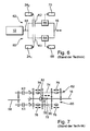
- Fig. 1
- Diagramme zur Erläuterung von für die Vorsteuerung des Antriebsmotors relevanten Größen,
- Fig. 2
- ein Flussdiagramm zur Erläuterung der Regelung des Motormoments,
- Fig. 3
- Diagramme zur Erläuterung eines Übersetzungswechsels mit Änderung eines Fahrerwunschmoments,
- Fig. 4
- Diagramme ähnlich der
Fig. 3 , - Fig. 5
- einen an sich bekannten Fahrzeugantriebsstrang, in den die Erfindung implementierbar ist,
- Fig. 6
- eine Prinzipdarstellung eines bekannten Parallelschaltgetriebes, und
- Fig. 7
- einen beispielhaften Aufbau eines 3-Wellen-Parallelschaltgetriebes.
- Bei der nachfolgenden Beschreibung der Erfindung wird auf einen Fahrzeugstrang beispielsweise gemäß
Fig. 5 Bezug genommen, in dem der Kupplungsaktor 24 zwei unabhängig voneinander von der Steuereinrichtung 30 entsprechend dort gespeicherten Programmen ansteuerbare Aktoren enthält, mit denen die beiden Kupplungen K1 und K2 (Fig. 5 und6 ) unabhängig von einander derart betätigbar sind, dass an jeder Kupplung ein definiertes Kupplungsmoment übertragbar ist. Der Schlupf der Kupplungen kann über deren Eingangsdrehzahl (vom Drehzahlsensor 46 erfasst) und die Drehzahlen der Ausgangswellen 72 und 74 (Fig. 6 ), von den Sensoren 32 erfasst, oder aus der Drehzahl der Ausgangswelle 16 (vom Sensor 34 erfasst) und den jeweils wirksamen Gängen (von der Steuereinrichtung 30 bekannt) ermittelt werden. - Während einer Gangschaltung bzw. einem Übersetzungswechsel wird die Kupplung des alten Gangs (alte Kupplung) geöffnet und die Kupplung des Zielgangs (neue Kupplung) auf ein bestimmtes Moment geschlossen. Dabei findet die eigentliche, am Fahrzeug wirksame Übersetzungsänderung bzw. der Gangwechsel statt. Durch das Öffnen der alten und Schließen der neuen Kupplung ändert sich das an der Ausgangswelle 16 wirksame Moment entsprechend der Gangübersetzung. Voraussetzung für einen ruckelfreien Übergang ist, dass im gesamten Verlauf beide Kupplungen schlupfen. Die Kupplungsmomente werden gesteuert, wohingegen das Motormoment geregelt wird. Die Regelung erfolgt derart, dass der Antriebsmotor 10 durch Veränderung der Stellung seines Laststellgliedes 53 an der Abtriebswelle 58 (
Fig. 5 ) ein Moment abgibt, das zu einem Schlupf der gesteuert betätigten Kupplungen führt. Die Regelung der Stellung des Laststellgliedes 53 bzw. des Moments der Abtriebswelle 58 erfolgt unter einer Vorsteuerung, der die eigentliche Regelung überlagert wird. - Im Folgenden wird anhand der
Fig. 1 die Vorsteuerung erläutert, wobei auf der Abszisse die Zeit angegeben ist und im oberen Teil derFig. 1 auf der Ordinate verschiedene Momente und im unteren Teil verschiedene Drehzahlen angegeben sind. Mit tPhase ist eine vorgebbare, beispielsweise durch das mit Hilfe des Wählhebels aktivierte Programm bestimmte Zeitdauer angegeben, während der ein Übersetzungswechsel erfolgt. - Die gestrichelte Linie I der
Fig. 1 gibt das vorgesteuerte Moment an der Abtriebswelle des Antriebsmotors an; die gestrichelt-einpunktige Kurve II gibt das von der alten Kupplung übertragbare Moment an. Die gestrichelt doppelpunktige Kurve III gibt das von der neuen Kupplung übertragbare Moment an. - Wie ersichtlich, wird vor Beginn eines Übersetzungswechsels das Moment der alten Kupplung leicht abgesenkt, so dass die alte Kupplung schlupft. Dieser anfängliche Schlupf der alten Kupplung, der im Programm vorgebbar ist, wird durch Veränderung des Motormoments während des gesamten Übersetzungswechsels auf einem konstanten Wert gehalten, wobei dieser Schlupf sowohl für die alte Kupplung als auch für die neue Kupplung gilt. Das von der alten Kupplung übertragene Moment wird beginnend mit dem Beginn der Übersetzungsänderung bis zum Ende der Übersetzungsänderung linear entsprechend der vorbestimmten Zeitdauer tPhase der Übersetzungsänderung auf einen sehr kleinen Wert abgesenkt. Das von der neuen Kupplung übertragbare Moment wird gemäß der Linie III vorzugsweise linear bis zu einem Endwert am Ende des Übersetzungswechsels gesteuert vergrößert, wobei das am Ende von der neuen Kupplung übertragbare Moment sich vorzugsweise zu dem zu Beginn der Übersetzungsänderung von der alten Kupplung übertragbaren Moment verhält wie die Anfangsübersetzung zur Endübersetzung, d.h. beispielsweise bei einer Zughochschaltung ist das Endmoment um so viel größer als das Anfangsmoment, wie sich bei gleicher Drehzahl des Antriebsmotors die Ausgangswelle bei dem kürzeren Gang schneller dreht als bei dem längeren Gang. Es ergibt sich die Vorsteuergerade IV, die gleich der Summe aus den jeweils augenblicklich übertragbaren Kupplungsmomenten ist, nämlich MCl, Alt + MCl,Neu.
- Dem Vorsteuermoment gemäß der Linie IV wird ein Moment MDyn,Alt, Begin überlagert, das dem dynamischen Anteil aus der Beschleunigung der alten Getriebeeingangswelle entspricht, d.h. MDyn,Alt = JEng• ωAlt· Dieser dynamische Anteil nimmt während des Übersetzungswechsels leicht ab.
- Zusätzlich wird ein Term MErr addiert, der der Kupplungsmomentenfehler an der alten Kupplung am Anfang der Überschneidung ist, der den Reibwert- sowie Tastpunktfehler enthält und naturgemäß zum Ende der Übersetzungsänderung hin auf Null abfällt.
- Für MErr gilt: MErr = MEng - MCl,Alt - MCl, Neu - MDyn,Alt, Begin - MAcc.
- MDyn, Alt,Begin wird bei Beginn der Übersetzungsänderung bestimmt. Bei MErr handelt es sich um ein Moment, das nur für die alte Kupplung gilt und nicht auf die neue übertragbar ist. Somit vermindert sich MErr während des Gangwechsels auf Null.
- MAcc ist ein Moment, das sich aus der Differenz zwischen den Beschleunigungen der Motordrehzahl und der alten Getriebeeingangswelle, gemessen am Anfang des Übersetzungswechsels, ergibt, und das beträgt:

- Für das Vorsteuerungsmotormoment ergibt sich somit insgesamt:

- Wenn man in vorstehende Formel die vorgenannte Formel für MErr einsetzt, ergibt sich für den Zeitpunkt t = 0:

- Zu dem Vorsteuerungs-Motormoment MEng, Vorsteuer kommt noch das Moment MAcc hinzu, das während des Übersetzungswechsels linear abnimmt.
- Die Zeitdauer tPhase ist voreinstellbar und bleibt während eines Übersetzungswechsels konstant.
- In den zu den Drehzahlen gehörenden Kurven zeigt die gestrichelte Kurve VI den Verlauf der Motordrehzahl ωEng, die einfach gepunktete Linie VI die Drehzahl ωalt der "alten" Eingangswelle und die doppelt gepunktete Linie VII die Drehzahl ωneu der "neuen" Eingangswelle.
- ωAcc stellt den über die Beschleunigung ωAlt hinausgehenden Teil der Beschleunigung der Motordrehzahl dar, d.h.:

- Ein Ziel der Schaltstrategie liegt darin, eine Beschleunigung der Motordrehzahl ωEng ZU erreichen, die gleich der Beschleunigung der alten Getriebeeingangswelle ist, d.h. ωAcc = 0.
- Der anhand der
Fig. 1 erläuterten Vorsteuerung des vom Antriebsmotor abgegebenen Moments wird zur Konstanthaltung des Schlupfes der Kupplungen eine Regelung überlagert, die einen D-Regler enthält, der als Eingangsgröße die zeitliche Ableitung des aktuellen Schlupfes ΔωAct benutzt. Parallel dazu wird ein P-Regler geschaltet, dessen Eingang die Differenz zwischen dem aktuellen Schlupf ΔωAct und dem Schlupf am Phasenanfang bzw. dem Anfang der Übersetzungsänderung ΔωAnf enthält. Die Aufgabe des P-Reglers liegt darin, zu verhindern, dass der Schlupf vollständig abgebaut wird. Der P-Regler wird erst dann eingeschaltet, wenn der Absolutbetrag des Schlupfes kleiner wird als der Schlupf, der am Anfang der Übersetzungsänderung bestimmt wurde. - Anhand des Flussdiagramms gemäß
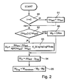
Fig. 2 wird im Folgenden eine Regelroutine erläutert:
Eine Regelroutine wird von der Steuereinrichtung 30 ausgelöst, die einen bevorstehenden Übersetzungswechsel anzeigt. Liegt dann der Beginn des Übersetzungswechsels vor (t=0; Schritt 90), so wird der Anfangsschlupf ΔωAnf gleich dem aktuellen bzw. augenblicklichen Schlupf ΔωAct gesetzt. Das Programm schreitet zum Schritt 92 fort, in dem überprüft wird, ob der Absolutwert von ΔωAct kleiner gleich dem Absolutwert von ΔωAnf ist. Ist dies der Fall, so wird im Schritt 93 vom Proportionalregler ein proportionales Motormoment Mp in folgender Größe bestimmt:
- Anschließend geht das Programm zum Schritt 94 weiter, in dem vom Differentialregler ein Motormoment MD = Δω Act.JEng errechnet wird, so dass in Schritt 95 ein Motormoment MEng = MVorsteuer- MD - MP eingestellt: wird.
- Für den Fall, dass die Bedingung des Schrittes 92 nicht vorliegt, wird das proportionale Motormoment im Schritt 96 auf 0 gesetzt und das Programm geht unmittelbar zum Schritt 94 weiter.
- Es sei darauf hingewiesen, dass auch andere Arten von Regelungen möglich sind und das nicht zwangsläufig beide, der D-Regler und der P-Regler vorhanden sein müssen.
- Im Folgenden wird die Steuerung der Kupplungsmomente erläutert:
- Wie anhand der
Fig. 1 dargestellt, wird das Kupplungsmoment der alten Kupplung (Kurve II) bis zu deren vollständiger Öffnung linear abgebaut. Die Überschneidungszeit bzw. die Zeitdauer des Übersetzungswechsels ist vorbestimmt und hängt beispielsweise vom jeweils gewählten Fahrprogramm ab. - Das Kupplungsmoment der neuen Kupplung wird vor einem Übersetzungswechsel auf 0 gehalten, wodurch gewährleistet ist, dass die Kupplung beim Übersetzungswechsel möglichst rasch auf die Momentenanforderung reagieren kann und ein mögliches Spiel im Getriebe überwunden wird.
- Um einer möglichen Änderung des Fahrerwunschmoments MFB während eines Übersetzungswechsels Rechnung tragen zu können, wird das Moment der neuen Kupplung MCl, Neu in jedem Interrupt nach folgender Formel neu berechnet (siehe
Fig. 3 ):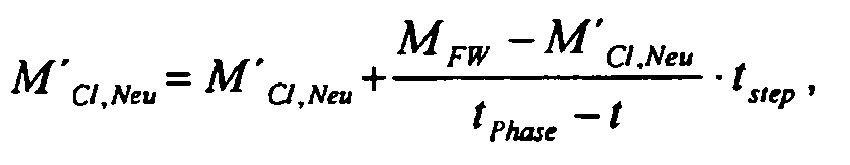
- In
Fig. 3 stellen dar:
die Kurve a) das Fahrerwunschmoment MFW, die Kurve b) das Sollmoment MCl,Alt, Soll der alten Kupplung, die Kurve c) das Ist-Moment M Cl, Alt, Ist der alten Kupplung, die Kurve d) das Sollmoment M Cl, Neu, Soll der neuen Kupplung und die Kurve e) das Ist-Moment M Cl, Neu, Ist der neuen Kupplung. - Damit die Kupplung am Anfang eines Übersetzungswechsels schneller "anspricht", wird parallel zu dem vorherigen Kupplungsmoment noch ein weiteres wie folgt berechnet:

- Die Parameter der min-Funktion werden experimentell bestimmt und an das jeweilige Fahrzeug angepasst. Verwendet wird immer das größere der beiden Momente M'Cl, Neu und M''Cl, Neu.
- Anhand der
Fig. 4 wird die Berechnung des Moments MCl,neu anhand der Formel
- Zum Zeitpunkt t=0:

- Zum Zeitpunkt t=10 ms:

- Zum Zeitpunkt t=20 ms:

- Zum Zeitpunkt t=30 ms (MFWM = ONm):

- Zum Zeitpunkt t=40 ms (MFWM = ONm):
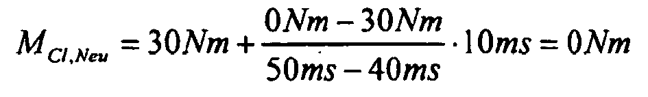
- Wie sich aus dem vorstehenden ergibt, ist durch die Berechnung sichergestellt, dass am Ende der Überschneidungsphase das Moment der neuen Kupplung dem Wert des Fahrerwunschmoments entspricht.
- Bei Volllastschaltungen, bei denen keine Erhöhung des Motormoments mehr möglich ist und die neue Kupplung wesentlich mehr Moment überträgt als angenommen, kann es vorkommen, dass die der Vorsteuerung überlagerte Regelung des Motormoments nicht ausreicht, um einen zu starken Schlupfabbau zu verhindern. In diesem Fall muss mit den Kupplungen reagiert werden. Bei Erkennung einer solchen Situation wird ein Bit gesetzt und das "Hochrampen" bzw. der Drehmomentanstieg der neuen Kupplung gestoppt.
-
- 10
- Antriebsmotor
- 12
- Kupplungseinrichtung
- 14
- Getriebe
- 16
- Ausgangswelle
- 18
- Kardanwelle
- 20
- Differential
- 22
- Hinterrad
- 24
- Kupplungsaktor
- 26
- Aktor
- 28
- Aktor
- 30
- Steuereinrichtung
- 32
- Drehzahlsensor
- 34
- Drehzahlsensor
- 36
- Stellungsgeber
- 38
- Wählhebel
- 40
- Motorsteuergerät
- 42
- Stellungsgeber
- 44
- Fahrpedal
- 46
- Drehzahlsensor
- 48
- Temperatursensor
- 50
- Sensoren
- 52
- Aktor
- 53
- Laststellglied
- 54
- Sensor
- 56
- Vorderrad
- 58
- Abtriebswelle
- 60
- Getriebezweig
- 62
- Getriebezweig
- 64
- Getriebeeinheit
- 66
- Getriebeeinheit
- 68
- Betätigungseinrichtung
- 70
- Betätigungseinrichtung
- 72
- Eingangswelle
- 74
- Eingangswelle
- 76
- Kupplungsglied
- 78
- Betätigungseinrichtung
- 80
- Wellglied
- 82
- Schaltglied
Claims (8)
- Verfahren zum Steuern eines Gangwechsels, insbesondere einer Zughochschaltung, in einem Parallelschaltgetriebe eines Fahrzeugs, welches Parallelschaltgetriebe zwei parallel zwischen einer Abtriebswelle (58) eines Antriebsmotors (10) des Fahrzeugs und einer Getriebeausgangswelle (16) liegende Getriebezweige (60, 62) aufweist, wobei eine Eingangswelle (72, 74) jedes Getriebezweiges mittels einer ihm zugeordneten Kupplung (K1, K2) mit der Ausgangswelle kuppelbar ist und die Eingangswelle jedes Getriebezweiges mit der Ausgangswelle mit wenigstens einer vorbestimmten Übersetzung in drehfesten Eingriff bringbar ist, so dass durch Öffnen der einen Kupplung und Schließen der anderen Kupplung ein zugkraftunterbrechungsfreier Wechsel der Übersetzung zwischen der Abtriebswelle und der Ausgangswelle möglich ist, wobei während eines Übersetzungswechsels die von den Kupplungen übertragbaren Momente in vorbestimmter Weise gesteuert verändert werden und die Last des Antriebsmotors (10) derart geregelt wird, dass ein vorbestimmter Schlupf der Kupplungen aufrechterhalten wird, wobei vor Beginn des Übersetzungswechsels an der die alte Übersetzung übertragenden Kupplung ein vorbestimmter Schlupf eingestellt wird, der während des Übersetzungswechsels aufrechterhalten wird, dadurch gekennzeichnet, dass die Kupplungsmomente gesteuert werden, und wobei die Last des Antriebsmotors (10) geregelt wird, und wobei die Regelung derart erfolgt, dass der Antriebsmotor (10) durch Veränderung der Stellung seines Laststeltgliedes (53) an der Abtriebswelle (58) ein Moment abgibt, das zu einem Schlupf der gesteuert betätigten Kupplungen führt.
- Verfahren zum Steuern eines Gangwechsels nach Anspruch 1, wobei das Moment der die alte Übersetzung übertragenden Kupplung während des Übersetzungswechsels kontinuierlich auf etwa Null und das Moment der die neue Übersetzung übertragenden Kupplung kontinuierlich von etwa Null auf einen vorbestimmten Wert verändert wird.
- Verfahren zum Steuern eines Gangwechsels nach Anspruch 2, wobei sich die Summe aus den von beiden Kupplungen übertragbaren Momenten während des Übersetzungswechsels kontinuierlich von einem Anfangswert auf einen Endwert ändert und sich der Anfangswert zum Endwert etwa wie die alte Übersetzung zur neuen Übersetzung verhält.
- Verfahren zum Steuern eines Gangwechsels nach einem der Ansprüche 1 bis 3, wobei die Last des Antriebsmotors entsprechend der Summe aus den augenblicklichen, von den Kupplungen übertragbaren Momenten vorgesteuert wird.
- Verfahren zum Steuern eines Gangwechsels nach Anspruch 4, wobei die Vorsteuerung der Last des Antriebsmotors zusätzlich entsprechend einer Zusatzgröße gesteuert wird, die wenigstens eine der folgenden Größen enthält:- dynamischer Anteil aus der Beschleunigung der die alte Übersetzung übertragenden Eingangswelle,- Moment, das sich aus der Differenz zwischen den Beschleunigungen der Drehzahl des Antriebsmotors und der die alte Übersetzung übertragenden Eingangswelle zu Beginn des Übersetzungswechsels ergibt,- Kupplungsmomentenfehler an der die alte Übersetzung übertragenden Kupplung zu Beginn des Übersetzungswechsels.
- Verfahren zum Steuern eines Gangwechsels nach einem der Ansprüche 1 bis 5, wobei die Last des Antriebsmotors zur Konstanthaltung des Schlupfes der Kupplungen mit Hilfe eines D-Reglers geregelt wird, dem als Eingangsgröße die zeitliche Ableitung des aktuellen Schlupfes zugeführt wird.
- Verfahren zum Steuern eines Gangwechsels nach einem der Ansprüche 1 bis 6, wobei die Last des Antriebsmotors zur Konstanthaltung des Schlupfes der Kupplungen mit Hilfe eines P-Reglers geregelt wird, dem als Eingangsgröße die Differenz aus dem augenblicklichen Schlupf und dem Schlupf zu Beginn des Übersetzungswechsels zugeführt wird.
- Vorrichtung zum Steuern eines Gangwechsels, insbesondere einer Zughochschaltung, in einem Parallelschaltgetriebe eines Fahrzeugs, welches Parallelschaltgetriebe zwei parallel zwischen einer Abtriebswelle (58) eines Antriebsmotors (10) des Fahrzeugs und einer Getriebeausgangswelle (16) liegende Getriebezweige (60, 62) aufweist, wobei eine Eingangswelle jedes Getriebezweiges mittels einer ihm zugeordneten Kupplung (K1, K2) mit der Ausgangswelle kuppelbar ist und die Eingangswelle jedes Getriebezweiges mit der Ausgangswelle mit wenigstens einer vorbestimmten Übersetzung in drehfesten Eingriff bringbar ist, so dass durch Öffnen der einen Kupplung und Schließen der anderen Kupplung ein zugkraftunterbrechungsfreier Wechsel der Übersetzung zwischen der Abtriebswelle und der Ausgangswelle möglich ist, welche Vorrichtung enthält:- eine Betätigungseinrichtung (241) für die Kupplung des ersten Getriebezweigs,- eine Betätigungseinrichtung (242) für die Kupplung des zweiten Getriebezweigs,- eine Betätigungseinrichtung (52) für ein Laststellglied des Antriebsmotors,- Sensoreinrichtungen zum Erfassen des Schlupfes der ersten Kupplung und der zweiten Kupplung, und- eine mit den Betätigungseinrichtungen und den Sensoreinrichtungen verbundene Steuereinrichtung (30) zum Steuern des Betriebs der Betätigungseinrichtungen derart, dass ein Verfahren nach einem der Ansprüche 1 bis 7 durchgeführt wird.
Applications Claiming Priority (2)
| Application Number | Priority Date | Filing Date | Title |
|---|---|---|---|
| DE102004007101 | 2004-02-13 | ||
| DE102004007101 | 2004-02-13 |
Publications (3)
| Publication Number | Publication Date |
|---|---|
| EP1564446A2 EP1564446A2 (de) | 2005-08-17 |
| EP1564446A3 EP1564446A3 (de) | 2010-02-24 |
| EP1564446B1 true EP1564446B1 (de) | 2012-03-14 |
Family
ID=34684038
Family Applications (1)
| Application Number | Title | Priority Date | Filing Date |
|---|---|---|---|
| EP05000775A Expired - Lifetime EP1564446B1 (de) | 2004-02-13 | 2005-01-15 | Verfahren und Vorrichtung zum Steuern eines Gangwechsels in einem Parallelschaltgetriebe eines Fahrzeuges |
Country Status (7)
| Country | Link |
|---|---|
| US (1) | US7337050B2 (de) |
| EP (1) | EP1564446B1 (de) |
| JP (1) | JP4867054B2 (de) |
| KR (1) | KR101238153B1 (de) |
| CN (1) | CN100532173C (de) |
| AT (1) | ATE549550T1 (de) |
| DE (1) | DE102005001981A1 (de) |
Families Citing this family (18)
| Publication number | Priority date | Publication date | Assignee | Title |
|---|---|---|---|---|
| DE102005022314A1 (de) * | 2005-05-10 | 2006-11-16 | Zf Friedrichshafen Ag | Verfahren zur Steuerung eines Getriebes eines Fahrzeugs |
| GB0609333D0 (en) | 2006-05-11 | 2006-06-21 | Zeroshift Ltd | Engagement member actuator control |
| GB0510129D0 (en) | 2005-05-18 | 2005-06-22 | Zeroshift Ltd | Sequential hub layout |
| JP4367399B2 (ja) * | 2005-10-21 | 2009-11-18 | トヨタ自動車株式会社 | 車両の駆動力制御装置 |
| DE102006024277A1 (de) * | 2006-05-24 | 2007-12-27 | Zf Friedrichshafen Ag | Verfahren und Vorrichtung zur Steuerung eines automatisierten Schaltgetriebes |
| JP5091953B2 (ja) * | 2007-10-22 | 2012-12-05 | 株式会社小松製作所 | 作業車両のエンジン出力制御装置および方法 |
| US7985163B2 (en) * | 2007-12-13 | 2011-07-26 | Ford Global Technologies, Llc | Adaptive clutch torque control for a powershift transmission |
| JP5205408B2 (ja) * | 2010-03-24 | 2013-06-05 | 株式会社小松製作所 | 作業車両及び作業車両の制御方法 |
| US8682545B2 (en) * | 2010-06-15 | 2014-03-25 | Ford Global Technologies, Llc | Damping oscillations during a gear ratio change of a dual clutch powershift transmission |
| FR2964715B1 (fr) * | 2010-09-13 | 2012-08-31 | Renault Sas | Procede de rangement de rapports montant pour boite de vitesses automatique d'un vehicule automobile |
| GB201109100D0 (en) | 2011-05-27 | 2011-07-13 | Zeroshift Ltd | Transmission system |
| US8775044B2 (en) * | 2011-06-08 | 2014-07-08 | Ford Global Technologies, Llc | Clutch torque trajectory correction to provide torque hole filling during a ratio upshift |
| CN104395648B (zh) | 2012-03-23 | 2017-06-30 | 环太平洋工程产品(1987)有限公司 | 具有提供替选传动比的替选扭矩传输路径的双离合器式动力变速器 |
| EP2828621B1 (de) | 2012-03-23 | 2017-09-06 | Pacific Rim Engineered Products (1987) Ltd. | Getriebekupplungsmechanismus für getriebe und zugehörige verfahren |
| CN105008169B (zh) * | 2012-12-19 | 2018-05-11 | 沃尔沃卡车公司 | 车辆的换档操作装置 |
| US9327733B2 (en) * | 2014-08-07 | 2016-05-03 | GM Global Technology Operations LLC | Method of controlling a vehicle during a clutch-to-clutch power upshift of a transmission |
| US9551415B2 (en) * | 2014-08-26 | 2017-01-24 | Ford Global Technologies, Llc | Output torque control method |
| US9551418B1 (en) * | 2015-07-10 | 2017-01-24 | Deere & Company | System and method for reducing engine flywheel power reduction while protecting drivetrain components |
Family Cites Families (22)
| Publication number | Priority date | Publication date | Assignee | Title |
|---|---|---|---|---|
| JPS5877138A (ja) * | 1981-11-04 | 1983-05-10 | Toyota Motor Corp | 自動変速機の変速制御方法 |
| JPS6189127A (ja) * | 1984-10-08 | 1986-05-07 | Nissan Motor Co Ltd | 自動変速機の変速シヨツク軽減装置 |
| JPH0721313B2 (ja) * | 1985-06-11 | 1995-03-08 | 三菱自動車工業株式会社 | 流体継手用クラッチの制御装置 |
| US4860607A (en) * | 1986-06-20 | 1989-08-29 | Toyota Jidosha Kabushiki Kaisha | Automatic transmission for automotive vehicle |
| US4790418A (en) * | 1987-04-30 | 1988-12-13 | Ford Motor Company | Transmission clutch loop transfer control |
| DE4204401A1 (de) * | 1992-02-14 | 1993-08-19 | Bosch Gmbh Robert | Einrichtung zur steuerung des abtriebsmoments eines automatischen schaltgetriebes |
| DE4333899A1 (de) * | 1993-10-05 | 1995-07-13 | Bosch Gmbh Robert | Verfahren zur Steuerung des Abtriebsmoments eines automatischen Schaltgetriebes |
| JP3706650B2 (ja) * | 1995-03-02 | 2005-10-12 | 本田技研工業株式会社 | 油圧作動式変速機の制御装置 |
| FR2732278B1 (fr) * | 1995-04-03 | 1997-06-20 | Magneti Marelli France | Systeme a boite de vitesses mecanique robotisee comprenant des moyens de commande perfectionnes a l'arret du vehicule |
| DE19631983C1 (de) * | 1996-08-08 | 1998-02-12 | Volkswagen Ag | Verfahren zum Schalten eines Doppelkupplungsgetriebes und Doppelkupplungsgetriebe mit Synchronisiereinrichtung |
| DE19939334A1 (de) * | 1999-08-19 | 2001-03-08 | Daimler Chrysler Ag | Verfahren zum Schalten eines Doppelkupplungsgetriebes und Doppelkupplungsgetriebe |
| DE10004530B4 (de) * | 2000-02-02 | 2012-11-15 | Volkswagen Ag | Verfahren zur Steuerung eines Doppelkupplungsgetriebes |
| JP2003522670A (ja) * | 2000-02-15 | 2003-07-29 | ルーク ラメレン ウント クツプルングスバウ ベタイリグングス コマンディートゲゼルシャフト | 変速機 |
| JP2003533658A (ja) * | 2000-05-17 | 2003-11-11 | ルーク ラメレン ウント クツプルングスバウ ベタイリグングス コマンディートゲゼルシャフト | クラッチを備えた伝動装置及びクラッチの操作のための方法 |
| DE10160308A1 (de) | 2001-01-12 | 2002-07-18 | Zf Sachs Ag | Verfahren zum Betrieb eines eine Mehrfach-Kupplungseinrichtung und ein Lastschaltgetriebe aufweisenden Antriebsstrangs und derartiger Antriebsstrang mit entprechender Steuereinheit |
| US6463821B1 (en) | 2001-06-29 | 2002-10-15 | Daimlerchrysler Corporation | Method of controlling a transmission having a dual clutch system |
| JP2003094987A (ja) * | 2001-09-20 | 2003-04-03 | Toyota Motor Corp | エンジンおよび変速機の制御装置 |
| JP3812432B2 (ja) * | 2001-12-10 | 2006-08-23 | 株式会社デンソー | 自動変速機の制御装置 |
| DE10390837D2 (de) * | 2002-03-07 | 2005-06-02 | Luk Lamellen & Kupplungsbau | Doppelkupplungsgetriebe und ein Verfahren zum Durchführen einer Hochschaltung von einem Anfangsgang in einen Zielgang bei dem Doppelkupplungsgetriebe eines Fahrzeuges |
| JP4034089B2 (ja) * | 2002-03-07 | 2008-01-16 | 株式会社日立製作所 | 自動変速機のクリープ制御装置及び方法 |
| EP1485269B1 (de) | 2002-03-07 | 2005-11-16 | LuK Lamellen und Kupplungsbau Beteiligungs KG | Doppelkupplungsgetriebe und ein verfahren zum durchführen einer hochschaltung von einem anfangsgang in einen zielgang bei dem doppelkupplungsgetriebe eines fahrzeuges |
| EP1485270A2 (de) * | 2002-03-07 | 2004-12-15 | LuK Lamellen und Kupplungsbau Beteiligungs KG | Verfahren zum durchführen einer schaltung bei einem doppelkupplungsgetriebe |
-
2005
- 2005-01-15 EP EP05000775A patent/EP1564446B1/de not_active Expired - Lifetime
- 2005-01-15 DE DE200510001981 patent/DE102005001981A1/de not_active Withdrawn
- 2005-01-15 AT AT05000775T patent/ATE549550T1/de active
- 2005-02-04 KR KR1020050010301A patent/KR101238153B1/ko not_active Expired - Fee Related
- 2005-02-08 CN CNB2005100913133A patent/CN100532173C/zh not_active Expired - Fee Related
- 2005-02-11 US US10/906,276 patent/US7337050B2/en not_active Expired - Fee Related
- 2005-02-14 JP JP2005036872A patent/JP4867054B2/ja not_active Expired - Fee Related
Also Published As
| Publication number | Publication date |
|---|---|
| KR101238153B1 (ko) | 2013-02-27 |
| CN1721248A (zh) | 2006-01-18 |
| EP1564446A3 (de) | 2010-02-24 |
| EP1564446A2 (de) | 2005-08-17 |
| JP2005226836A (ja) | 2005-08-25 |
| CN100532173C (zh) | 2009-08-26 |
| DE102005001981A1 (de) | 2005-09-01 |
| US20050182544A1 (en) | 2005-08-18 |
| ATE549550T1 (de) | 2012-03-15 |
| JP4867054B2 (ja) | 2012-02-01 |
| KR20060041679A (ko) | 2006-05-12 |
| US7337050B2 (en) | 2008-02-26 |
Similar Documents
| Publication | Publication Date | Title |
|---|---|---|
| EP1564446B1 (de) | Verfahren und Vorrichtung zum Steuern eines Gangwechsels in einem Parallelschaltgetriebe eines Fahrzeuges | |
| EP1439087B1 (de) | Verfahren zur Steuerung und Regelung des Kupplungs- und Motordrehmoments während eines Schaltvorgangs eines automatisierten Schaltgetriebes oder eines Doppelkupplungsgetriebes | |
| DE112010002949B4 (de) | Verfahren und Vorrichtung zum Steuern eines Doppelkupplungsgetriebes | |
| DE112013001042B4 (de) | Verfahren zur Ermittlung eines Tastpunkts | |
| DE10228709A1 (de) | Verfahren zum Adaptieren der Einstellung einer Kupplung in einem unkonventionellen Antriebsstrang eines Fahrzeugs | |
| WO2002094601A2 (de) | Steuerverfahren für kraftfahrzeuge mit automatisierter kupplunsvorrichtung | |
| EP1497151A1 (de) | Verfahren, vorrichtung und deren verwendung zum betrieb eines kraftfahrzeuges | |
| DE10230612A1 (de) | Verfahren, Vorrichtung und deren Verwendung zum Betrieb eines Kraftfahrzeuges, insbesondere zum Verbessern eines Anfahrvorganges | |
| DE112012006767T5 (de) | Fahrzeuggetriebesteuerung | |
| DE19709417A1 (de) | Vorrichtung zur Ansteuerung eines Drehmomentübertragungssystems und eines Getriebes, sowie ein Verfahren hierfür | |
| DE19932755A1 (de) | Steuerungsvorrichtung | |
| EP2240709B1 (de) | Vorrichtung und verfahren zum verhindern von fehlschaltungen in automatischen getrieben von kraftfahrzeugen | |
| DE102014208557B4 (de) | Verfahren zur Steuerung und/oder Regelung der Schaltung eines Doppelkupplungsgetriebes eines Kraftfahrzeugs | |
| EP1382479B1 (de) | Verfahren zur Durchführung eines Anfahrvorgangs bei einem eine Doppel- oder Mehrfach-Kupplungseinrichtung aufweisenden Kraftfahrzeug-Antriebssystem | |
| WO2008104148A1 (de) | Verfahren und vorrichtung zum steuern der kupplungen eines parallelschaltgetriebes bei einem gangwechsel | |
| DE10261723B4 (de) | Verfahren zur Adaptation einer Schaltkennlinie einer Lastschaltkupplung eines Kraftfahrzeuggetriebes | |
| DE102004033716A1 (de) | Verfahren zum Betrieb eines eine Mehrfach-Kupplungseinrichtung und ein Lastschaltgetriebe aufweisenden Antriebsstrangs und derartiger Antriebsstrang mit entsprechender Steuereinheit | |
| EP3760889B1 (de) | Antriebsstrang eines fahrzeugs sowie verfahren zum betreiben eines antriebsstrangs eines fahrzeugs | |
| AT508077B1 (de) | Verfahren zum betreiben eines ein lastschalt-wendegetriebe aufweisenden kraftfahrzeuges | |
| DE10312397A1 (de) | Verfahren, Vorrichtung und deren Verwendung zum Betrieb eines Kraftfahrzeuge insbesondere zur Ansteuerung eines automatisierten Schaltgetriebes | |
| DE10322619A1 (de) | Automatisiertes Schaltgetriebe sowie Verfahren zum Betreiben einer Getriebeeinrichtung | |
| WO2004059195A1 (de) | Verfahren und vorrichtung zur fehlerüberwachung einer elektronischen steuereinrichtung eines im antriebsstrang eines kraftfahrzeugs angeordneten automatischen getriebes | |
| EP1566560B1 (de) | Verfahren zum Durchführen einer Tastpunktadaption an zumindest einer Kupplung eines automatisierten Getriebes und Einrichtung, insbesondere zum Durchführen des Verfahrens | |
| DE102021209152B3 (de) | Verfahren zur Steuerung eines Schaltvorganges | |
| EP1637424B1 (de) | Verfahren und Vorrichtung zum Regeln der Fahrstabilität eines Kraftfahrzeugs |
Legal Events
| Date | Code | Title | Description |
|---|---|---|---|
| PUAI | Public reference made under article 153(3) epc to a published international application that has entered the european phase |
Free format text: ORIGINAL CODE: 0009012 |
|
| AK | Designated contracting states |
Kind code of ref document: A2 Designated state(s): AT BE BG CH CY CZ DE DK EE ES FI FR GB GR HU IE IS IT LI LT LU MC NL PL PT RO SE SI SK TR |
|
| AX | Request for extension of the european patent |
Extension state: AL BA HR LV MK YU |
|
| PUAL | Search report despatched |
Free format text: ORIGINAL CODE: 0009013 |
|
| AK | Designated contracting states |
Kind code of ref document: A3 Designated state(s): AT BE BG CH CY CZ DE DK EE ES FI FR GB GR HU IE IS IT LI LT LU MC NL PL PT RO SE SI SK TR |
|
| AX | Request for extension of the european patent |
Extension state: AL BA HR LV MK YU |
|
| 17P | Request for examination filed |
Effective date: 20100824 |
|
| 17Q | First examination report despatched |
Effective date: 20100924 |
|
| AKX | Designation fees paid |
Designated state(s): AT BE BG CH CY CZ DE DK EE ES FI FR GB GR HU IE IS IT LI LT LU MC NL PL PT RO SE SI SK TR |
|
| R17C | First examination report despatched (corrected) |
Effective date: 20100930 |
|
| RAP1 | Party data changed (applicant data changed or rights of an application transferred) |
Owner name: SCHAEFFLER TECHNOLOGIES GMBH & CO. KG |
|
| 17Q | First examination report despatched |
Effective date: 20110311 |
|
| GRAP | Despatch of communication of intention to grant a patent |
Free format text: ORIGINAL CODE: EPIDOSNIGR1 |
|
| GRAS | Grant fee paid |
Free format text: ORIGINAL CODE: EPIDOSNIGR3 |
|
| GRAA | (expected) grant |
Free format text: ORIGINAL CODE: 0009210 |
|
| AK | Designated contracting states |
Kind code of ref document: B1 Designated state(s): AT BE BG CH CY CZ DE DK EE ES FI FR GB GR HU IE IS IT LI LT LU MC NL PL PT RO SE SI SK TR |
|
| RAP1 | Party data changed (applicant data changed or rights of an application transferred) |
Owner name: SCHAEFFLER TECHNOLOGIES AG & CO. KG |
|
| REG | Reference to a national code |
Ref country code: GB Ref legal event code: FG4D Free format text: NOT ENGLISH |
|
| REG | Reference to a national code |
Ref country code: AT Ref legal event code: REF Ref document number: 549550 Country of ref document: AT Kind code of ref document: T Effective date: 20120315 Ref country code: CH Ref legal event code: EP |
|
| REG | Reference to a national code |
Ref country code: IE Ref legal event code: FG4D Free format text: LANGUAGE OF EP DOCUMENT: GERMAN |
|
| REG | Reference to a national code |
Ref country code: DE Ref legal event code: R096 Ref document number: 502005012522 Country of ref document: DE Effective date: 20120503 |
|
| REG | Reference to a national code |
Ref country code: NL Ref legal event code: VDEP Effective date: 20120314 |
|
| PG25 | Lapsed in a contracting state [announced via postgrant information from national office to epo] |
Ref country code: LT Free format text: LAPSE BECAUSE OF FAILURE TO SUBMIT A TRANSLATION OF THE DESCRIPTION OR TO PAY THE FEE WITHIN THE PRESCRIBED TIME-LIMIT Effective date: 20120314 |
|
| LTIE | Lt: invalidation of european patent or patent extension |
Effective date: 20120314 |
|
| PG25 | Lapsed in a contracting state [announced via postgrant information from national office to epo] |
Ref country code: FI Free format text: LAPSE BECAUSE OF FAILURE TO SUBMIT A TRANSLATION OF THE DESCRIPTION OR TO PAY THE FEE WITHIN THE PRESCRIBED TIME-LIMIT Effective date: 20120314 Ref country code: GR Free format text: LAPSE BECAUSE OF FAILURE TO SUBMIT A TRANSLATION OF THE DESCRIPTION OR TO PAY THE FEE WITHIN THE PRESCRIBED TIME-LIMIT Effective date: 20120615 |
|
| PG25 | Lapsed in a contracting state [announced via postgrant information from national office to epo] |
Ref country code: CY Free format text: LAPSE BECAUSE OF FAILURE TO SUBMIT A TRANSLATION OF THE DESCRIPTION OR TO PAY THE FEE WITHIN THE PRESCRIBED TIME-LIMIT Effective date: 20120314 |
|
| PG25 | Lapsed in a contracting state [announced via postgrant information from national office to epo] |
Ref country code: PL Free format text: LAPSE BECAUSE OF FAILURE TO SUBMIT A TRANSLATION OF THE DESCRIPTION OR TO PAY THE FEE WITHIN THE PRESCRIBED TIME-LIMIT Effective date: 20120314 Ref country code: CZ Free format text: LAPSE BECAUSE OF FAILURE TO SUBMIT A TRANSLATION OF THE DESCRIPTION OR TO PAY THE FEE WITHIN THE PRESCRIBED TIME-LIMIT Effective date: 20120314 Ref country code: RO Free format text: LAPSE BECAUSE OF FAILURE TO SUBMIT A TRANSLATION OF THE DESCRIPTION OR TO PAY THE FEE WITHIN THE PRESCRIBED TIME-LIMIT Effective date: 20120314 Ref country code: IS Free format text: LAPSE BECAUSE OF FAILURE TO SUBMIT A TRANSLATION OF THE DESCRIPTION OR TO PAY THE FEE WITHIN THE PRESCRIBED TIME-LIMIT Effective date: 20120714 Ref country code: EE Free format text: LAPSE BECAUSE OF FAILURE TO SUBMIT A TRANSLATION OF THE DESCRIPTION OR TO PAY THE FEE WITHIN THE PRESCRIBED TIME-LIMIT Effective date: 20120314 Ref country code: SE Free format text: LAPSE BECAUSE OF FAILURE TO SUBMIT A TRANSLATION OF THE DESCRIPTION OR TO PAY THE FEE WITHIN THE PRESCRIBED TIME-LIMIT Effective date: 20120314 Ref country code: SI Free format text: LAPSE BECAUSE OF FAILURE TO SUBMIT A TRANSLATION OF THE DESCRIPTION OR TO PAY THE FEE WITHIN THE PRESCRIBED TIME-LIMIT Effective date: 20120314 |
|
| PG25 | Lapsed in a contracting state [announced via postgrant information from national office to epo] |
Ref country code: SK Free format text: LAPSE BECAUSE OF FAILURE TO SUBMIT A TRANSLATION OF THE DESCRIPTION OR TO PAY THE FEE WITHIN THE PRESCRIBED TIME-LIMIT Effective date: 20120314 Ref country code: PT Free format text: LAPSE BECAUSE OF FAILURE TO SUBMIT A TRANSLATION OF THE DESCRIPTION OR TO PAY THE FEE WITHIN THE PRESCRIBED TIME-LIMIT Effective date: 20120716 |
|
| PLBE | No opposition filed within time limit |
Free format text: ORIGINAL CODE: 0009261 |
|
| STAA | Information on the status of an ep patent application or granted ep patent |
Free format text: STATUS: NO OPPOSITION FILED WITHIN TIME LIMIT |
|
| PG25 | Lapsed in a contracting state [announced via postgrant information from national office to epo] |
Ref country code: DK Free format text: LAPSE BECAUSE OF FAILURE TO SUBMIT A TRANSLATION OF THE DESCRIPTION OR TO PAY THE FEE WITHIN THE PRESCRIBED TIME-LIMIT Effective date: 20120314 Ref country code: NL Free format text: LAPSE BECAUSE OF FAILURE TO SUBMIT A TRANSLATION OF THE DESCRIPTION OR TO PAY THE FEE WITHIN THE PRESCRIBED TIME-LIMIT Effective date: 20120314 |
|
| 26N | No opposition filed |
Effective date: 20121217 |
|
| PG25 | Lapsed in a contracting state [announced via postgrant information from national office to epo] |
Ref country code: IT Free format text: LAPSE BECAUSE OF FAILURE TO SUBMIT A TRANSLATION OF THE DESCRIPTION OR TO PAY THE FEE WITHIN THE PRESCRIBED TIME-LIMIT Effective date: 20120314 |
|
| REG | Reference to a national code |
Ref country code: DE Ref legal event code: R097 Ref document number: 502005012522 Country of ref document: DE Effective date: 20121217 |
|
| PG25 | Lapsed in a contracting state [announced via postgrant information from national office to epo] |
Ref country code: ES Free format text: LAPSE BECAUSE OF FAILURE TO SUBMIT A TRANSLATION OF THE DESCRIPTION OR TO PAY THE FEE WITHIN THE PRESCRIBED TIME-LIMIT Effective date: 20120625 |
|
| BERE | Be: lapsed |
Owner name: SCHAEFFLER TECHNOLOGIES A.G. & CO. KG Effective date: 20130131 |
|
| PG25 | Lapsed in a contracting state [announced via postgrant information from national office to epo] |
Ref country code: BG Free format text: LAPSE BECAUSE OF FAILURE TO SUBMIT A TRANSLATION OF THE DESCRIPTION OR TO PAY THE FEE WITHIN THE PRESCRIBED TIME-LIMIT Effective date: 20120614 |
|
| PG25 | Lapsed in a contracting state [announced via postgrant information from national office to epo] |
Ref country code: MC Free format text: LAPSE BECAUSE OF NON-PAYMENT OF DUE FEES Effective date: 20130131 |
|
| REG | Reference to a national code |
Ref country code: CH Ref legal event code: PL |
|
| GBPC | Gb: european patent ceased through non-payment of renewal fee |
Effective date: 20130115 |
|
| REG | Reference to a national code |
Ref country code: IE Ref legal event code: MM4A |
|
| PG25 | Lapsed in a contracting state [announced via postgrant information from national office to epo] |
Ref country code: BE Free format text: LAPSE BECAUSE OF NON-PAYMENT OF DUE FEES Effective date: 20130131 Ref country code: CH Free format text: LAPSE BECAUSE OF NON-PAYMENT OF DUE FEES Effective date: 20130131 Ref country code: LI Free format text: LAPSE BECAUSE OF NON-PAYMENT OF DUE FEES Effective date: 20130131 |
|
| PG25 | Lapsed in a contracting state [announced via postgrant information from national office to epo] |
Ref country code: GB Free format text: LAPSE BECAUSE OF NON-PAYMENT OF DUE FEES Effective date: 20130115 |
|
| PG25 | Lapsed in a contracting state [announced via postgrant information from national office to epo] |
Ref country code: IE Free format text: LAPSE BECAUSE OF NON-PAYMENT OF DUE FEES Effective date: 20130115 |
|
| REG | Reference to a national code |
Ref country code: AT Ref legal event code: MM01 Ref document number: 549550 Country of ref document: AT Kind code of ref document: T Effective date: 20130115 |
|
| REG | Reference to a national code |
Ref country code: DE Ref legal event code: R081 Ref document number: 502005012522 Country of ref document: DE Owner name: SCHAEFFLER TECHNOLOGIES AG & CO. KG, DE Free format text: FORMER OWNER: LUK LAMELLEN UND KUPPLUNGSBAU BETEILIGUNGS KG, 77815 BUEHL, DE Effective date: 20120314 Ref country code: DE Ref legal event code: R081 Ref document number: 502005012522 Country of ref document: DE Owner name: SCHAEFFLER TECHNOLOGIES AG & CO. KG, DE Free format text: FORMER OWNER: SCHAEFFLER TECHNOLOGIES AG & CO. KG, 91074 HERZOGENAURACH, DE Effective date: 20140213 Ref country code: DE Ref legal event code: R081 Ref document number: 502005012522 Country of ref document: DE Owner name: SCHAEFFLER TECHNOLOGIES GMBH & CO. KG, DE Free format text: FORMER OWNER: LUK LAMELLEN UND KUPPLUNGSBAU BETEILIGUNGS KG, 77815 BUEHL, DE Effective date: 20120314 Ref country code: DE Ref legal event code: R081 Ref document number: 502005012522 Country of ref document: DE Owner name: SCHAEFFLER TECHNOLOGIES GMBH & CO. KG, DE Free format text: FORMER OWNER: SCHAEFFLER TECHNOLOGIES AG & CO. KG, 91074 HERZOGENAURACH, DE Effective date: 20140213 |
|
| PG25 | Lapsed in a contracting state [announced via postgrant information from national office to epo] |
Ref country code: AT Free format text: LAPSE BECAUSE OF NON-PAYMENT OF DUE FEES Effective date: 20130115 |
|
| REG | Reference to a national code |
Ref country code: DE Ref legal event code: R081 Ref document number: 502005012522 Country of ref document: DE Owner name: SCHAEFFLER TECHNOLOGIES AG & CO. KG, DE Free format text: FORMER OWNER: SCHAEFFLER TECHNOLOGIES GMBH & CO. KG, 91074 HERZOGENAURACH, DE Effective date: 20150213 |
|
| PG25 | Lapsed in a contracting state [announced via postgrant information from national office to epo] |
Ref country code: TR Free format text: LAPSE BECAUSE OF FAILURE TO SUBMIT A TRANSLATION OF THE DESCRIPTION OR TO PAY THE FEE WITHIN THE PRESCRIBED TIME-LIMIT Effective date: 20120314 |
|
| PG25 | Lapsed in a contracting state [announced via postgrant information from national office to epo] |
Ref country code: LU Free format text: LAPSE BECAUSE OF NON-PAYMENT OF DUE FEES Effective date: 20130115 Ref country code: HU Free format text: LAPSE BECAUSE OF FAILURE TO SUBMIT A TRANSLATION OF THE DESCRIPTION OR TO PAY THE FEE WITHIN THE PRESCRIBED TIME-LIMIT; INVALID AB INITIO Effective date: 20050115 |
|
| REG | Reference to a national code |
Ref country code: FR Ref legal event code: PLFP Year of fee payment: 12 |
|
| REG | Reference to a national code |
Ref country code: FR Ref legal event code: PLFP Year of fee payment: 13 |
|
| REG | Reference to a national code |
Ref country code: FR Ref legal event code: PLFP Year of fee payment: 14 |
|
| PGFP | Annual fee paid to national office [announced via postgrant information from national office to epo] |
Ref country code: FR Payment date: 20210121 Year of fee payment: 17 |
|
| PGFP | Annual fee paid to national office [announced via postgrant information from national office to epo] |
Ref country code: DE Payment date: 20210319 Year of fee payment: 17 |
|
| REG | Reference to a national code |
Ref country code: DE Ref legal event code: R119 Ref document number: 502005012522 Country of ref document: DE |
|
| PG25 | Lapsed in a contracting state [announced via postgrant information from national office to epo] |
Ref country code: DE Free format text: LAPSE BECAUSE OF NON-PAYMENT OF DUE FEES Effective date: 20220802 |
|
| PG25 | Lapsed in a contracting state [announced via postgrant information from national office to epo] |
Ref country code: FR Free format text: LAPSE BECAUSE OF NON-PAYMENT OF DUE FEES Effective date: 20220131 |
|
| P01 | Opt-out of the competence of the unified patent court (upc) registered |
Effective date: 20230523 |