EP1564446A2 - Verfahren und Vorrichtung zum Steuern eines Gangwechsels in einem Parallelschaltgetriebe eines Fahrzeuges - Google Patents
Verfahren und Vorrichtung zum Steuern eines Gangwechsels in einem Parallelschaltgetriebe eines Fahrzeuges Download PDFInfo
- Publication number
- EP1564446A2 EP1564446A2 EP05000775A EP05000775A EP1564446A2 EP 1564446 A2 EP1564446 A2 EP 1564446A2 EP 05000775 A EP05000775 A EP 05000775A EP 05000775 A EP05000775 A EP 05000775A EP 1564446 A2 EP1564446 A2 EP 1564446A2
- Authority
- EP
- European Patent Office
- Prior art keywords
- clutch
- transmission
- output shaft
- change
- gear
- Prior art date
- Legal status (The legal status is an assumption and is not a legal conclusion. Google has not performed a legal analysis and makes no representation as to the accuracy of the status listed.)
- Granted
Links
Images


Classifications
-
- E—FIXED CONSTRUCTIONS
- E03—WATER SUPPLY; SEWERAGE
- E03C—DOMESTIC PLUMBING INSTALLATIONS FOR FRESH WATER OR WASTE WATER; SINKS
- E03C1/00—Domestic plumbing installations for fresh water or waste water; Sinks
- E03C1/12—Plumbing installations for waste water; Basins or fountains connected thereto; Sinks
- E03C1/28—Odour seals
- E03C1/284—Odour seals having U-shaped trap
-
- F—MECHANICAL ENGINEERING; LIGHTING; HEATING; WEAPONS; BLASTING
- F16—ENGINEERING ELEMENTS AND UNITS; GENERAL MEASURES FOR PRODUCING AND MAINTAINING EFFECTIVE FUNCTIONING OF MACHINES OR INSTALLATIONS; THERMAL INSULATION IN GENERAL
- F16H—GEARING
- F16H61/00—Control functions within control units of change-speed- or reversing-gearings for conveying rotary motion ; Control of exclusively fluid gearing, friction gearing, gearings with endless flexible members or other particular types of gearing
- F16H61/04—Smoothing ratio shift
- F16H61/0437—Smoothing ratio shift by using electrical signals
-
- F—MECHANICAL ENGINEERING; LIGHTING; HEATING; WEAPONS; BLASTING
- F16—ENGINEERING ELEMENTS AND UNITS; GENERAL MEASURES FOR PRODUCING AND MAINTAINING EFFECTIVE FUNCTIONING OF MACHINES OR INSTALLATIONS; THERMAL INSULATION IN GENERAL
- F16H—GEARING
- F16H61/00—Control functions within control units of change-speed- or reversing-gearings for conveying rotary motion ; Control of exclusively fluid gearing, friction gearing, gearings with endless flexible members or other particular types of gearing
- F16H61/04—Smoothing ratio shift
- F16H2061/0462—Smoothing ratio shift by controlling slip rate during gear shift transition
-
- F—MECHANICAL ENGINEERING; LIGHTING; HEATING; WEAPONS; BLASTING
- F16—ENGINEERING ELEMENTS AND UNITS; GENERAL MEASURES FOR PRODUCING AND MAINTAINING EFFECTIVE FUNCTIONING OF MACHINES OR INSTALLATIONS; THERMAL INSULATION IN GENERAL
- F16H—GEARING
- F16H2306/00—Shifting
- F16H2306/40—Shifting activities
- F16H2306/44—Removing torque from current gears
-
- F—MECHANICAL ENGINEERING; LIGHTING; HEATING; WEAPONS; BLASTING
- F16—ENGINEERING ELEMENTS AND UNITS; GENERAL MEASURES FOR PRODUCING AND MAINTAINING EFFECTIVE FUNCTIONING OF MACHINES OR INSTALLATIONS; THERMAL INSULATION IN GENERAL
- F16H—GEARING
- F16H2306/00—Shifting
- F16H2306/40—Shifting activities
- F16H2306/52—Applying torque to new gears
-
- F—MECHANICAL ENGINEERING; LIGHTING; HEATING; WEAPONS; BLASTING
- F16—ENGINEERING ELEMENTS AND UNITS; GENERAL MEASURES FOR PRODUCING AND MAINTAINING EFFECTIVE FUNCTIONING OF MACHINES OR INSTALLATIONS; THERMAL INSULATION IN GENERAL
- F16H—GEARING
- F16H61/00—Control functions within control units of change-speed- or reversing-gearings for conveying rotary motion ; Control of exclusively fluid gearing, friction gearing, gearings with endless flexible members or other particular types of gearing
- F16H61/68—Control functions within control units of change-speed- or reversing-gearings for conveying rotary motion ; Control of exclusively fluid gearing, friction gearing, gearings with endless flexible members or other particular types of gearing specially adapted for stepped gearings
- F16H61/684—Control functions within control units of change-speed- or reversing-gearings for conveying rotary motion ; Control of exclusively fluid gearing, friction gearing, gearings with endless flexible members or other particular types of gearing specially adapted for stepped gearings without interruption of drive
- F16H61/688—Control functions within control units of change-speed- or reversing-gearings for conveying rotary motion ; Control of exclusively fluid gearing, friction gearing, gearings with endless flexible members or other particular types of gearing specially adapted for stepped gearings without interruption of drive with two inputs, e.g. selection of one of two torque-flow paths by clutches
-
- F—MECHANICAL ENGINEERING; LIGHTING; HEATING; WEAPONS; BLASTING
- F16—ENGINEERING ELEMENTS AND UNITS; GENERAL MEASURES FOR PRODUCING AND MAINTAINING EFFECTIVE FUNCTIONING OF MACHINES OR INSTALLATIONS; THERMAL INSULATION IN GENERAL
- F16H—GEARING
- F16H63/00—Control outputs from the control unit to change-speed- or reversing-gearings for conveying rotary motion or to other devices than the final output mechanism
- F16H63/40—Control outputs from the control unit to change-speed- or reversing-gearings for conveying rotary motion or to other devices than the final output mechanism comprising signals other than signals for actuating the final output mechanisms
- F16H63/50—Signals to an engine or motor
Definitions
- the invention relates to a method and a device for controlling a gear change, in particular a traction upshift, in a parallel transmission of a vehicle.
- Fig. 5 shows the drive train of a conventional vehicle.
- a drive motor 2, 10 is connected via a coupling device 12 with a gear 14, the output shaft 16 in the illustrated example via a propeller shaft 18 and a differential 20 with the rear wheels 22 of a vehicle is connected.
- a clutch actuator 24 is provided for actuating the clutch device 12.
- actuators 26 and 28 are provided.
- the actuators 24, 26, 28 are from an electronic control device 30 with a microprocessor and associated Save controlled.
- Inputs of the electronic control device 30 are in the actuators contained position sensors and speed sensors 32 and 34 for detecting, for example a speed of a transmission shaft and the speed of the propeller shaft 34 and the Output shaft 16 connected.
- Next is an input of the controller 30 with a Position sensor 36 of a selector lever 38 for activating various programs of Control device 30 connected.
- an engine control unit 40 To control the drive motor 10 is an engine control unit 40, whose inputs with a position sensor 42 for detecting the position of an accelerator pedal, a speed sensor 46 for detecting the rotational speed of the crankshaft of the internal combustion engine, a temperature sensor 48 for detecting an engine temperature, sensors 50 for detecting further operating parameters of Motors and a position sensor for detecting the position of an actuator 52 for a load actuator 54 of the drive motor 10 are connected. Further, sensors 54 for detecting the rotational speeds of the front wheels 56 and the rear wheels 22 may be provided, which are connected to the engine control unit 40.
- the engine control unit 40 is connected to the transmission control device 30 via a data line, for example a CAN bus 58, via which data communication takes place. Fig.
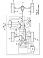
- FIG. 6 shows schematically the structure of the coupling device 12 and the transmission 14.
- An output shaft 58 of the drive motor 10 is rotatably connected to two parallel transmission branches 60 and 62, which are rotatably connected respectively via a gear unit 64 and 66 to the output shaft 16.
- the gear units 64 and 66 may be conventional transmissions whose gears are rotatably connected in a conventional manner via an actuator 68 and 70, respectively.
- the clutches K1 and K2 can be actuated by means of actuators 24 1 and 24 2 .
- Fig. 7 shows the structure of a Doppelkupplungs- or parallel transmission, which has a total of three shafts, namely two input shafts 72 and 74, which can be rotatably connected via different sets of wheels with one of the common output shaft 16.
- the wheelsets are in constant contact with each other.
- the wheels of the input shafts 72 and 74 can be synchronized in a conventional manner by means of axially displaceable on the shafts coupling members 76 with the shafts and brought into rotationally fixed engagement.
- an actuator 78 with a selector member 80 and a switching member 82 is provided, wherein the selector, for example, the actuator 26 (FIG.
- the clutches K1 and K2 are on the input side in rotationally fixed engagement with the output shaft 58 of the drive motor.
- the clutches K1 and K2 are actuated by the clutch actuators 24 1 and 24 2 (FIG. 6).
- K2 with open clutch one of the gears of the transmission branch 62 are switched, so that by merely opening the Clutch K1 and simultaneous closing of the clutch K2 a traction free Translation change from a gear of the transmission branch 60 to a gear of the Transmission branch 62 can be done.
- This gear or gear ratio should as possible for the driver of a vehicle be carried out comfortably, depending on the position of the selector lever 38 in the control device 30th different programs can be activated, according to which the gear change as quickly as possible sporty, as soft and comfortable as possible or otherwise optimized.
- the actuation of the clutches K1 and K2 and the load actuator of the drive motor 10th is thus carried out according to programs that are stored for example in the control device 30 are, from where via the bus 58 and the controller 40 and the actuator 52 of the Load actuator 53 is actuated.
- the transmission side Half of the new clutch but rotates with the speed of the transmission input shaft is through a subsequent lowering of the engine torque below the clutch torque of the new Clutch the engine speed to the speed of the newly effective transmission input shaft pulled down.
- the deceleration of the engine brings an additional torque that comes from the energy stored in the flywheel of the engine comes from and via the transmission input shaft acts on the transmission output shaft.
- the reduction of the engine torque corresponds to the Torque contribution due to the deceleration of the engine, so that by slowing down the Motors is brought no additional moment on the transmission output shaft.
- the new Clutch is now fully closed and the engine torque is on his original value.
- the invention is based on the object, a method and an apparatus for its Specify implementation, with the or a gear change of a parallel transmission, In particular, a pull-up, designed as comfortable as possible under all conditions can be.
- the process part of the object is provided with a method for controlling a Gear change, in particular a traction upshift, in a parallel transmission of a Vehicle solved, which parallel shift two parallel between an output shaft a drive motor of the vehicle and a transmission output shaft lying Has transmission branches, wherein an input shaft of each transmission branch by means of a him associated clutch is coupled to the output shaft and the input shaft each Transmission branch with the output shaft with at least one predetermined translation in rotatable engagement can be brought, so that by opening the one clutch and closing the other coupling a traction interruption free change of the translation between the Output shaft and the output shaft is possible, in which method during a Translation change the transferable from the clutches moments in a predetermined Modified controlled manner and the load of the drive motor is controlled such that a predetermined slip of the clutches is maintained.
- an implementation of the method according to the invention is such that the moment the old transmission transmitting clutch during the translation change continuously at about zero and the moment of transferring the new translation Clutch is continuously changed from about zero to a predetermined value.
- the sum of the transferable from both clutches moments changes continuously during the translation change from an initial value to a final value and the initial value to end value approximates the old translation to the new one Translation.
- the load of the drive motor Advantageously regulated by means of a D-controller, as the input the temporal Derivation of the current slip is supplied.
- the load of the drive motor to keep constant the slip of the clutches alternatively or additionally regulated by means of a P-controller, as the input Difference between the instantaneous slip and the slip at the beginning of the Translation change is supplied.
- the clutch actuator 24 two independent from each other from the controller 30 corresponding programs stored therein includes actuatable actuators, with which the two clutches K1 and K2 (FIGS. 5 and 6) independently of each other are actuated such that at each coupling a defined Clutch torque is transferable.
- the slip of the couplings can over their Input speed (detected by the speed sensor 46) and the rotational speeds of the output shafts 72nd and 74 (FIG. 6) detected by the sensors 32 or from the rotational speed of the output shaft 16 (from FIG Sensor 34 detected) and the respective effective gears (known from the control device 30) be determined.
- the clutch of the old Gangs open and the clutch of the target gear (new clutch) on closed certain moment. It finds the actual, effective on the vehicle Translation change or the gear change instead.
- By opening the old and closing the new clutch changes the effective torque on the output shaft 16 accordingly the gear ratio.
- Condition for a smooth transition is that throughout Course slip both clutches.
- the clutch torques are controlled, whereas the engine torque is regulated.
- the control is such that the drive motor 10 by Changing the position of its load actuator 53 on the output shaft 58 (Fig. 5) a moment which leads to a slip of the controlled actuated clutches.
- the regulation of Position of the load actuator 53 and the torque of the output shaft 58 takes place under a Feedforward, which is superimposed on the actual control.
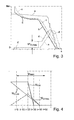
- t phase is given a predetermined, for example, by the activated by means of the selector lever program certain period of time during which a ratio change occurs.
- the dashed line I of FIG. 1 is the pilot-controlled torque on the output shaft of the Drive motor on; the dashed-one-point curve II gives that of the old clutch transferable moment. The dashed double-dotted curve III gives that of the new Clutch transferable moment.
- the torque of the old clutch is slightly lowered before the start of a gear change, so that the old clutch slips.
- This initial slip of the old clutch which can be specified in the program, is maintained at a constant value by changing the engine torque throughout the gear change, which slip applies to both the old clutch and the new clutch.
- the torque transmitted by the old clutch is lowered linearly from the beginning of the gear change until the end of the gear shift according to the predetermined time t phase of the gear change to a very small value.
- the transmittable by the new clutch torque is increased according to the line III preferably linearly controlled up to a final value at the end of the ratio change, wherein the transmittable at the end of the new clutch torque preferably behaves to the transmittable at the beginning of the ratio change of the old clutch torque like the initial gear ratio to the final gear ratio, ie, for example, in a Switzerlandrochscrien the final torque is so much greater than the initial torque, as at the same speed of the drive motor, the output shaft rotates faster in the shorter gear than in the longer gear.
- the result is the pilot straight line IV, which is equal to the sum of the momentarily transferable clutch torques, namely M Cl, Alt + M Cl, New .
- M Err is added, which is the clutch torque error at the old clutch at the beginning of the overlap that contains the friction and touch point errors and naturally drops to zero at the end of the gear change.
- M Err M Eng - M Cl, Alt - M Cl , New - M Dyn, Alt, Begin - M Acc.
- M Dyn, Alt, Begin is determined at the beginning of the translation change.
- M Err is a moment that applies only to the old clutch and is not transferable to the new one. Thus, M Err decreases to zero during the gear shift.
- the torque M Acc which decreases linearly during the ratio change, is added to the precontrol engine torque M Eng, pilot control .
- the time period t phase can be preset and remains constant during a ratio change.
- the dashed curve VI shows the course of the engine speed ⁇ Eng , the dotted line VI the speed ⁇ old of the "old” input shaft and the double-dotted line VII the speed ⁇ new of the "new" input shaft.
- pilot control of the output torque from the drive motor is superimposed to maintain the slip of the clutches a scheme that contains a D-controller, which uses the time derivative of the actual slip ⁇ Act as an input.
- a P-controller is switched whose input contains the difference between the actual slip ⁇ Act and the slip at the beginning of the phase or the beginning of the ratio change ⁇ Anf .
- the job of the P-Regulator is to prevent the slippage from breaking down completely.
- the P controller is turned on only when the absolute amount of slip becomes smaller than the slip determined at the beginning of the speed change.
- step 92 In the event that the condition of step 92 is not present, the proportional Motor torque is set to 0 in step 96 and the program immediately proceeds to step 94 further.
- the clutch torque of the old clutch (curve II) is up to the complete opening linear degraded.
- the overlap time or the duration of the Translation change is predetermined and depends, for example, on the selected one Driving program off.
- the clutch torque of the new clutch is 0 before a gear ratio change which ensures that the clutch during the translation change as possible can respond quickly to the torque request and a possible game in the transmission is overcome.
- t phase is the interchange time period
- t step is the step size.
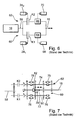
- Fig. 3 represent: the curve a) the driver command torque M FW , the curve b) the target torque M Cl, Alt, target the old clutch, the curve c) the actual torque M Cl, Alt, Is the old clutch, the curve d) the target torque M Cl, new, the new clutch and the curve e) the actual torque M Cl, New, is the new clutch.
- the parameters of the min function are determined experimentally and adapted to the respective vehicle.
- the larger of the two moments M ' Cl, New and M'' Cl, New is always used.
- the calculation ensures that at the end the overlapping phase the moment of the new clutch the value of Driver request torque corresponds.
Landscapes
- Engineering & Computer Science (AREA)
- General Engineering & Computer Science (AREA)
- Mechanical Engineering (AREA)
- Environmental & Geological Engineering (AREA)
- Health & Medical Sciences (AREA)
- Life Sciences & Earth Sciences (AREA)
- Hydrology & Water Resources (AREA)
- Public Health (AREA)
- Water Supply & Treatment (AREA)
- Control Of Transmission Device (AREA)
- Hydraulic Clutches, Magnetic Clutches, Fluid Clutches, And Fluid Joints (AREA)
- Control Of Vehicle Engines Or Engines For Specific Uses (AREA)
Abstract
Description
Fig. 6 zeigt schematisch den Aufbau der Kupplungseinrichtung 12 und des Getriebes 14. Eine Abtriebswelle 58 des Antriebsmotors 10 ist drehfest mit zwei parallelen Getriebezweigen 60 und 62 verbunden, die jeweils über eine Getriebeeinheit 64 bzw. 66 mit der Ausgangswelle 16 drehfest verbunden sind. Die Getriebeeinheiten 64 und 66 können herkömmliche Schaltgetriebe sein, deren Gänge jeweils in an sich bekannter Weise über eine Betätigungseinrichtung 68 bzw. 70 drehfest verbunden sind. Die Kupplungen K1 bzw. K2 sind mittels Aktoren 241 bzw. 242 betätigbar.
- dynamischer Anteil aus der Beschleunigung der die alte Übersetzung übertragenden Eingangswelle,
- Moment, das sich aus der Differenz zwischen den Beschleunigungen der Drehzahl des Antriebsmotors und der die alte Übersetzung übertragenden Eingangswelle zu Beginn des Übersetzungswechsels ergibt,
- Kupplungsmomentenfehler an der die alte Übersetzung übertragenden Kupplung zu Beginn des Übersetzungswechsels.
- eine Betätigungseinrichtung für die Kupplung des ersten Getriebezweigs,
- eine Betätigungseinrichtung für die Kupplung des zweiten Getriebezweigs,
- eine Betätigungseinrichtung für ein Laststellglied des Antriebsmotors,
- Sensoreinrichtungen zum Erfassen des Schlupfes der ersten Kupplung und der zweiten Kupplung, und
- eine mit den Betätigungseinrichtungen und den Sensoreinrichtungen verbundene Steuereinrichtung zum Steuern des Betriebs der Betätigungseinrichtungen derart, dass ein Verfahren nach einem der Ansprüche 1 bis 8 durchgeführt wird.
- Fig. 1
- Diagramme zur Erläuterung von für die Vorsteuerung des Antriebsmotors relevanten Größen,
- Fig. 2
- ein Flussdiagramm zur Erläuterung der Regelung des Motormoments,
- Fig. 3
- Diagramme zur Erläuterung eines Übersetzungswechsels mit Änderung eines Fahrerwunschmoments,
- Fig. 4
- Diagramme ähnlich der Fig. 3,
- Fig. 5
- einen an sich bekannten Fahrzeugantriebsstrang, in den die Erfindung implementierbar ist,
- Fig. 6
- eine Prinzipdarstellung eines bekannten Parallelschaltgetriebes, und
- Fig. 7
- einen beispielhaften Aufbau eines 3-Wellen-Parallelschaltgetriebes.
Eine Regelroutine wird von der Steuereinrichtung 30 ausgelöst, die einen bevorstehenden Übersetzungswechsel anzeigt. Liegt dann der Beginn des Übersetzungswechsels vor (t=0; Schritt 90), so wird der Anfangsschlupf ΔωAnf gleich dem aktuellen bzw. augenblicklichen Schlupf ΔωAct gesetzt. Das Programm schreitet zum Schritt 92 fort, in dem überprüft wird, ob der Absolutwert von ΔωAct kleiner gleich dem Absolutwert von ΔωAnf ist. Ist dies der Fall, so wird im Schritt 93 vom Proportionalregler ein proportionales Motormoment Mp in folgender Größe bestimmt:
die Kurve a) das Fahrerwunschmoment MFW, die Kurve b) das Sollmoment MCl,Alt, Soll der alten Kupplung, die Kurve c) das Ist-Moment M Cl, Alt, Ist der alten Kupplung, die Kurve d) das Sollmoment M Cl, Neu, Soll der neuen Kupplung und die Kurve e) das Ist-Moment M Cl, Neu, Ist der neuen Kupplung.
- 10
- Antriebsmotor
- 12
- Kupplungseinrichtung
- 14
- Getriebe
- 16
- Ausgangswelle
- 18
- Kardanwelle
- 20
- Differential
- 22
- Hinterrad
- 24
- Kupplungsaktor
- 26
- Aktor
- 28
- Aktor
- 30
- Steuereinrichtung
- 32
- Drehzahlsensor
- 34
- Drehzahlsensor
- 36
- Stellungsgeber
- 38
- Wählhebel
- 40
- Motorsteuergerät
- 42
- Stellungsgeber
- 44
- Fahrpedal
- 46
- Drehzahlsensor
- 48
- Temperatursensor
- 50
- Sensoren
- 52
- Aktor
- 53
- Laststellglied
- 54
- Sensor
- 56
- Vorderrad
- 58
- Abtriebswelle
- 60
- Getriebezweig
- 62
- Getriebezweig
- 64
- Getriebeeinheit
- 66
- Getriebeeinheit
- 68
- Betätigungseinrichtung
- 70
- Betätigungseinrichtung
- 72
- Eingangswelle
- 74
- Eingangswelle
- 76
- Kupplungsglied
- 78
- Betätigungseinrichtung
- 80
- Wellglied
- 82
- Schaltglied
Claims (9)
- Verfahren zum Steuern eines Gangwechsels, insbesondere einer Zughochschaltung, in einem Parallelschaltgetriebe eines Fahrzeugs, welches Parallelschaltgetriebe zwei parallel zwischen einer Abtriebswelle (58) eines Antriebsmotors (10) des Fahrzeugs und einer Getriebeausgangswelle (16) liegende Getriebezweige (60, 62) aufweist, wobei eine Eingangswelle (72, 74) jedes Getriebezweiges mittels einer ihm zugeordneten Kupplung (K1, K2) mit der Ausgangswelle kuppelbar ist und die Eingangswelle jedes Getriebezweiges mit der Ausgangswelle mit wenigstens einer vorbestimmten Übersetzung in drehfesten Eingriff bringbar ist, so dass durch Öffnen der einen Kupplung und Schließen der anderen Kupplung ein zugkraftunterbrechungsfreier Wechsel der Übersetzung zwischen der Abtriebswelle und der Ausgangswelle möglich ist,
bei welchem Verfahren während eines Übersetzungswechsels die von den Kupplungen übertragbaren Momente in vorbestimmter Weise gesteuert verändert werden und die Last des Antriebsmotors (10) derart geregelt wird, dass ein vorbestimmter Schlupf der Kupplungen aufrechterhalten wird. - Verfahren zum Steuern eines Gangwechsels nach Anspruch 1, wobei vor Beginn des Übersetzungswechsels an der die alte Übersetzung übertragenden Kupplung ein vorbestimmter Schlupf eingestellt wird, der während des Übersetzungswechsels aufrechterhalten wird.
- Verfahren zum Steuern eines Gangwechsels nach Anspruch 1 oder 2, wobei das Moment der die alte Übersetzung übertragenden Kupplung während des Übersetzungswechsels kontinuierlich auf etwa Null und das Moment der die neue Übersetzung übertragenden Kupplung kontinuierlich von etwa Null auf einen vorbestimmten Wert verändert wird.
- Verfahren zum Steuern eines Gangwechsels nach Anspruch 3, wobei sich die Summe aus den von beiden Kupplungen übertragbaren Momenten während des Übersetzungswechsels kontinuierlich von einem Anfangswert auf einen Endwert ändert und sich der Anfangswert zum Endwert etwa wie die alte Übersetzung zur neuen Übersetzung verhält.
- Verfahren zum Steuern eines Gangwechsels nach einem der Ansprüche 1 bis 4, wobei die Last des Antriebsmotors entsprechend der Summe aus den augenblicklichen, von den Kupplungen übertragbaren Momenten vorgesteuert wird.
- Verfahren zum Steuern eines Gangwechsels nach Anspruch 5, wobei die Vorsteuerung der Last des Antriebsmotors zusätzlich entsprechend einer Zusatzgröße gesteuert wird, die wenigstens eine der folgenden Größen enthält:dynamischer Anteil aus der Beschleunigung der die alte Übersetzung übertragenden Eingangswelle,Moment, das sich aus der Differenz zwischen den Beschleunigungen der Drehzahl des Antriebsmotors und der die alte Übersetzung übertragenden Eingangswelle zu Beginn des Übersetzungswechsels ergibt,Kupplungsmomentenfehler an der die alte Übersetzung übertragenden Kupplung zu Beginn des Übersetzungswechsels.
- Verfahren zum Steuern eines Gangwechsels nach einem der Ansprüche 1 bis 6, wobei die Last des Antriebsmotors zur Konstanthaltung des Schlupfes der Kupplungen mit Hilfe eines D-Reglers geregelt wird, dem als Eingangsgröße die zeitliche Ableitung des aktuellen Schlupfes zugeführt wird.
- Verfahren zum Steuern eines Gangwechsels nach einem der Ansprüche 1 bis 7, wobei die Last des Antriebsmotors zur Konstanthaltung des Schlupfes der Kupplungen mit Hilfe eines P-Reglers geregelt wird, dem als Eingangsgröße die Differenz aus dem augenblicklichen Schlupf und dem Schlupf zu Beginn des Übersetzungswechsels zugeführt wird.
- Vorrichtung zum Steuern eines Gangwechsels, insbesondere einer Zughochschaltung, in einem Parallelschaltgetriebe eines Fahrzeugs, welches Parallelschaltgetriebe zwei parallel zwischen einer Abtriebswelle (58) eines Antriebsmotors (10) des Fahrzeugs und einer Getriebeausgangswelle (16) liegende Getriebezweige (60, 62) aufweist, wobei eine Eingangswelle jedes Getriebezweiges mittels einer ihm zugeordneten Kupplung (K1, K2) mit der Ausgangswelle kuppelbar ist und die Eingangswelle jedes Getriebezweiges mit der Ausgangswelle mit wenigstens einer vorbestimmten Übersetzung in drehfesten Eingriff bringbar ist, so dass durch Öffnen der einen Kupplung und Schließen der anderen Kupplung ein zugkraftunterbrechungsfreier Wechsel der Übersetzung zwischen der Abtriebswelle und der Ausgangswelle möglich ist, welche Vorrichtung enthält:eine Betätigungseinrichtung (241) für die Kupplung des ersten Getriebezweigs,eine Betätigungseinrichtung (242) für die Kupplung des zweiten Getriebezweigs,eine Betätigungseinrichtung (52) für ein Laststellglied des Antriebsmotors,Sensoreinrichtungen zum Erfassen des Schlupfes der ersten Kupplung und der zweiten Kupplung, undeine mit den Betätigungseinrichtungen und den Sensoreinrichtungen verbundene Steuereinrichtung (30) zum Steuern des Betriebs der Betätigungseinrichtungen derart, dass ein Verfahren nach einem der Ansprüche 1 bis 8 durchgeführt wird.
Applications Claiming Priority (2)
| Application Number | Priority Date | Filing Date | Title |
|---|---|---|---|
| DE102004007101 | 2004-02-13 | ||
| DE102004007101 | 2004-02-13 |
Publications (3)
| Publication Number | Publication Date |
|---|---|
| EP1564446A2 true EP1564446A2 (de) | 2005-08-17 |
| EP1564446A3 EP1564446A3 (de) | 2010-02-24 |
| EP1564446B1 EP1564446B1 (de) | 2012-03-14 |
Family
ID=34684038
Family Applications (1)
| Application Number | Title | Priority Date | Filing Date |
|---|---|---|---|
| EP05000775A Expired - Lifetime EP1564446B1 (de) | 2004-02-13 | 2005-01-15 | Verfahren und Vorrichtung zum Steuern eines Gangwechsels in einem Parallelschaltgetriebe eines Fahrzeuges |
Country Status (7)
| Country | Link |
|---|---|
| US (1) | US7337050B2 (de) |
| EP (1) | EP1564446B1 (de) |
| JP (1) | JP4867054B2 (de) |
| KR (1) | KR101238153B1 (de) |
| CN (1) | CN100532173C (de) |
| AT (1) | ATE549550T1 (de) |
| DE (1) | DE102005001981A1 (de) |
Cited By (5)
| Publication number | Priority date | Publication date | Assignee | Title |
|---|---|---|---|---|
| WO2007132209A3 (en) * | 2006-05-11 | 2008-01-24 | Zeroshift Ltd | Transmission system and method for performing a gearshift |
| US8291784B2 (en) | 2005-05-18 | 2012-10-23 | Zeroshift Limited | Transmission layout |
| CN105008169A (zh) * | 2012-12-19 | 2015-10-28 | 沃尔沃卡车公司 | 车辆的换档操作装置 |
| CN105387197A (zh) * | 2014-08-26 | 2016-03-09 | 福特全球技术公司 | 输出扭矩控制方法 |
| US9303731B2 (en) | 2011-05-27 | 2016-04-05 | Zeroshift Transmissions Limited | Transmission system |
Families Citing this family (13)
| Publication number | Priority date | Publication date | Assignee | Title |
|---|---|---|---|---|
| DE102005022314A1 (de) * | 2005-05-10 | 2006-11-16 | Zf Friedrichshafen Ag | Verfahren zur Steuerung eines Getriebes eines Fahrzeugs |
| JP4367399B2 (ja) * | 2005-10-21 | 2009-11-18 | トヨタ自動車株式会社 | 車両の駆動力制御装置 |
| DE102006024277A1 (de) * | 2006-05-24 | 2007-12-27 | Zf Friedrichshafen Ag | Verfahren und Vorrichtung zur Steuerung eines automatisierten Schaltgetriebes |
| JP5091953B2 (ja) * | 2007-10-22 | 2012-12-05 | 株式会社小松製作所 | 作業車両のエンジン出力制御装置および方法 |
| US7985163B2 (en) * | 2007-12-13 | 2011-07-26 | Ford Global Technologies, Llc | Adaptive clutch torque control for a powershift transmission |
| JP5205408B2 (ja) * | 2010-03-24 | 2013-06-05 | 株式会社小松製作所 | 作業車両及び作業車両の制御方法 |
| US8682545B2 (en) * | 2010-06-15 | 2014-03-25 | Ford Global Technologies, Llc | Damping oscillations during a gear ratio change of a dual clutch powershift transmission |
| FR2964715B1 (fr) * | 2010-09-13 | 2012-08-31 | Renault Sas | Procede de rangement de rapports montant pour boite de vitesses automatique d'un vehicule automobile |
| US8775044B2 (en) * | 2011-06-08 | 2014-07-08 | Ford Global Technologies, Llc | Clutch torque trajectory correction to provide torque hole filling during a ratio upshift |
| CN104395648B (zh) | 2012-03-23 | 2017-06-30 | 环太平洋工程产品(1987)有限公司 | 具有提供替选传动比的替选扭矩传输路径的双离合器式动力变速器 |
| EP2828621B1 (de) | 2012-03-23 | 2017-09-06 | Pacific Rim Engineered Products (1987) Ltd. | Getriebekupplungsmechanismus für getriebe und zugehörige verfahren |
| US9327733B2 (en) * | 2014-08-07 | 2016-05-03 | GM Global Technology Operations LLC | Method of controlling a vehicle during a clutch-to-clutch power upshift of a transmission |
| US9551418B1 (en) * | 2015-07-10 | 2017-01-24 | Deere & Company | System and method for reducing engine flywheel power reduction while protecting drivetrain components |
Citations (2)
| Publication number | Priority date | Publication date | Assignee | Title |
|---|---|---|---|---|
| DE10160308A1 (de) | 2001-01-12 | 2002-07-18 | Zf Sachs Ag | Verfahren zum Betrieb eines eine Mehrfach-Kupplungseinrichtung und ein Lastschaltgetriebe aufweisenden Antriebsstrangs und derartiger Antriebsstrang mit entprechender Steuereinheit |
| DE10308700A1 (de) | 2002-03-07 | 2003-10-09 | Luk Lamellen & Kupplungsbau | Doppelkupplungsgetriebe und ein Verfahren zum Durchführen einer Hochschaltung von einem Anfangsgang in einen Zielgang bei dem Doppelkupplungsgetriebe eines Fahrzeuges |
Family Cites Families (20)
| Publication number | Priority date | Publication date | Assignee | Title |
|---|---|---|---|---|
| JPS5877138A (ja) * | 1981-11-04 | 1983-05-10 | Toyota Motor Corp | 自動変速機の変速制御方法 |
| JPS6189127A (ja) * | 1984-10-08 | 1986-05-07 | Nissan Motor Co Ltd | 自動変速機の変速シヨツク軽減装置 |
| JPH0721313B2 (ja) * | 1985-06-11 | 1995-03-08 | 三菱自動車工業株式会社 | 流体継手用クラッチの制御装置 |
| US4860607A (en) * | 1986-06-20 | 1989-08-29 | Toyota Jidosha Kabushiki Kaisha | Automatic transmission for automotive vehicle |
| US4790418A (en) * | 1987-04-30 | 1988-12-13 | Ford Motor Company | Transmission clutch loop transfer control |
| DE4204401A1 (de) * | 1992-02-14 | 1993-08-19 | Bosch Gmbh Robert | Einrichtung zur steuerung des abtriebsmoments eines automatischen schaltgetriebes |
| DE4333899A1 (de) * | 1993-10-05 | 1995-07-13 | Bosch Gmbh Robert | Verfahren zur Steuerung des Abtriebsmoments eines automatischen Schaltgetriebes |
| JP3706650B2 (ja) * | 1995-03-02 | 2005-10-12 | 本田技研工業株式会社 | 油圧作動式変速機の制御装置 |
| FR2732278B1 (fr) * | 1995-04-03 | 1997-06-20 | Magneti Marelli France | Systeme a boite de vitesses mecanique robotisee comprenant des moyens de commande perfectionnes a l'arret du vehicule |
| DE19631983C1 (de) * | 1996-08-08 | 1998-02-12 | Volkswagen Ag | Verfahren zum Schalten eines Doppelkupplungsgetriebes und Doppelkupplungsgetriebe mit Synchronisiereinrichtung |
| DE19939334A1 (de) * | 1999-08-19 | 2001-03-08 | Daimler Chrysler Ag | Verfahren zum Schalten eines Doppelkupplungsgetriebes und Doppelkupplungsgetriebe |
| DE10004530B4 (de) * | 2000-02-02 | 2012-11-15 | Volkswagen Ag | Verfahren zur Steuerung eines Doppelkupplungsgetriebes |
| JP2003522670A (ja) * | 2000-02-15 | 2003-07-29 | ルーク ラメレン ウント クツプルングスバウ ベタイリグングス コマンディートゲゼルシャフト | 変速機 |
| JP2003533658A (ja) * | 2000-05-17 | 2003-11-11 | ルーク ラメレン ウント クツプルングスバウ ベタイリグングス コマンディートゲゼルシャフト | クラッチを備えた伝動装置及びクラッチの操作のための方法 |
| US6463821B1 (en) | 2001-06-29 | 2002-10-15 | Daimlerchrysler Corporation | Method of controlling a transmission having a dual clutch system |
| JP2003094987A (ja) * | 2001-09-20 | 2003-04-03 | Toyota Motor Corp | エンジンおよび変速機の制御装置 |
| JP3812432B2 (ja) * | 2001-12-10 | 2006-08-23 | 株式会社デンソー | 自動変速機の制御装置 |
| DE10390837D2 (de) * | 2002-03-07 | 2005-06-02 | Luk Lamellen & Kupplungsbau | Doppelkupplungsgetriebe und ein Verfahren zum Durchführen einer Hochschaltung von einem Anfangsgang in einen Zielgang bei dem Doppelkupplungsgetriebe eines Fahrzeuges |
| JP4034089B2 (ja) * | 2002-03-07 | 2008-01-16 | 株式会社日立製作所 | 自動変速機のクリープ制御装置及び方法 |
| EP1485270A2 (de) * | 2002-03-07 | 2004-12-15 | LuK Lamellen und Kupplungsbau Beteiligungs KG | Verfahren zum durchführen einer schaltung bei einem doppelkupplungsgetriebe |
-
2005
- 2005-01-15 EP EP05000775A patent/EP1564446B1/de not_active Expired - Lifetime
- 2005-01-15 DE DE200510001981 patent/DE102005001981A1/de not_active Withdrawn
- 2005-01-15 AT AT05000775T patent/ATE549550T1/de active
- 2005-02-04 KR KR1020050010301A patent/KR101238153B1/ko not_active Expired - Fee Related
- 2005-02-08 CN CNB2005100913133A patent/CN100532173C/zh not_active Expired - Fee Related
- 2005-02-11 US US10/906,276 patent/US7337050B2/en not_active Expired - Fee Related
- 2005-02-14 JP JP2005036872A patent/JP4867054B2/ja not_active Expired - Fee Related
Patent Citations (2)
| Publication number | Priority date | Publication date | Assignee | Title |
|---|---|---|---|---|
| DE10160308A1 (de) | 2001-01-12 | 2002-07-18 | Zf Sachs Ag | Verfahren zum Betrieb eines eine Mehrfach-Kupplungseinrichtung und ein Lastschaltgetriebe aufweisenden Antriebsstrangs und derartiger Antriebsstrang mit entprechender Steuereinheit |
| DE10308700A1 (de) | 2002-03-07 | 2003-10-09 | Luk Lamellen & Kupplungsbau | Doppelkupplungsgetriebe und ein Verfahren zum Durchführen einer Hochschaltung von einem Anfangsgang in einen Zielgang bei dem Doppelkupplungsgetriebe eines Fahrzeuges |
Cited By (8)
| Publication number | Priority date | Publication date | Assignee | Title |
|---|---|---|---|---|
| US8291784B2 (en) | 2005-05-18 | 2012-10-23 | Zeroshift Limited | Transmission layout |
| WO2007132209A3 (en) * | 2006-05-11 | 2008-01-24 | Zeroshift Ltd | Transmission system and method for performing a gearshift |
| US8171814B2 (en) | 2006-05-11 | 2012-05-08 | Zeroshift Limited | Transmission system and method for performing a gearshift |
| US9303731B2 (en) | 2011-05-27 | 2016-04-05 | Zeroshift Transmissions Limited | Transmission system |
| CN105008169A (zh) * | 2012-12-19 | 2015-10-28 | 沃尔沃卡车公司 | 车辆的换档操作装置 |
| US9890854B2 (en) | 2012-12-19 | 2018-02-13 | Volvo Truck Corporation | Vehicular shift operation apparatus |
| CN105387197A (zh) * | 2014-08-26 | 2016-03-09 | 福特全球技术公司 | 输出扭矩控制方法 |
| CN105387197B (zh) * | 2014-08-26 | 2019-01-29 | 福特全球技术公司 | 输出扭矩控制方法 |
Also Published As
| Publication number | Publication date |
|---|---|
| KR101238153B1 (ko) | 2013-02-27 |
| CN1721248A (zh) | 2006-01-18 |
| EP1564446A3 (de) | 2010-02-24 |
| JP2005226836A (ja) | 2005-08-25 |
| CN100532173C (zh) | 2009-08-26 |
| EP1564446B1 (de) | 2012-03-14 |
| DE102005001981A1 (de) | 2005-09-01 |
| US20050182544A1 (en) | 2005-08-18 |
| ATE549550T1 (de) | 2012-03-15 |
| JP4867054B2 (ja) | 2012-02-01 |
| KR20060041679A (ko) | 2006-05-12 |
| US7337050B2 (en) | 2008-02-26 |
Similar Documents
| Publication | Publication Date | Title |
|---|---|---|
| EP1564446B1 (de) | Verfahren und Vorrichtung zum Steuern eines Gangwechsels in einem Parallelschaltgetriebe eines Fahrzeuges | |
| EP2131075B1 (de) | System und Verfahren zum Betreiben eines automatisierten Getriebes bei Ausfall eines Motordrehzahlgebers oder einer Busverbindung zwischen Steuermodulen | |
| EP2269882B1 (de) | Verfahren zum Betreiben eines Fahrzeugs in einem Segelnmodus | |
| WO2011006466A1 (de) | Kupplungstastpunkte | |
| EP2063152B1 (de) | Verfahren zum Schalten eines Doppelkupplungsgetriebes | |
| DE102008023360A1 (de) | Verfahren zum Plausibilisieren der Stellung des Kupplungsaktors einer Kupplung, Verfahren zum Bestimmen des Tastpunktes einer Kupplung sowie Vorrichtung zum Durchführen der Verfahren | |
| DE112012006767T5 (de) | Fahrzeuggetriebesteuerung | |
| DE19721034A1 (de) | Kraftfahrzeug | |
| DE102011018316A1 (de) | Verfahren zur Steuerung eines automatisierten Schaltgetriebes | |
| EP2240709B1 (de) | Vorrichtung und verfahren zum verhindern von fehlschaltungen in automatischen getrieben von kraftfahrzeugen | |
| EP0759513B1 (de) | Steuerung einer automatischen Kupplung in Abhängigkeit vom Motordrehmoment | |
| EP1382479B1 (de) | Verfahren zur Durchführung eines Anfahrvorgangs bei einem eine Doppel- oder Mehrfach-Kupplungseinrichtung aufweisenden Kraftfahrzeug-Antriebssystem | |
| EP1321329A2 (de) | Kraftfahrzeug mit einem Mehrfachkupplungs-Mehrganggetriebe | |
| DE112008000375B4 (de) | Verfahren und Vorrichtung zum Steuern der Kupplungen eines Parallelschaltgetriebes bei einem Gangwechsel | |
| EP3232093B1 (de) | Verfahren zum mindern von störungen in einem kraftfahrzeug-antriebsstrang bei einem gangwechsel | |
| DE102004033716A1 (de) | Verfahren zum Betrieb eines eine Mehrfach-Kupplungseinrichtung und ein Lastschaltgetriebe aufweisenden Antriebsstrangs und derartiger Antriebsstrang mit entsprechender Steuereinheit | |
| EP1509710A1 (de) | Automatisiertes schaltgetriebe sowie verfahren zum betreiben einer getriebeeinrichtung | |
| DE10312397A1 (de) | Verfahren, Vorrichtung und deren Verwendung zum Betrieb eines Kraftfahrzeuge insbesondere zur Ansteuerung eines automatisierten Schaltgetriebes | |
| EP1566560B1 (de) | Verfahren zum Durchführen einer Tastpunktadaption an zumindest einer Kupplung eines automatisierten Getriebes und Einrichtung, insbesondere zum Durchführen des Verfahrens | |
| EP1762450B1 (de) | Verfahren und Vorrichtung zum Steuern des Betriebs einer Kupplung und eines Antriebsmotors im Antriebsstrang eines Fahrzeugs | |
| DE102004029076A1 (de) | Verfahren zum Ansteuern einer Kupplung in einem Getriebe, insbesondere einem automatisierten Getriebe, eines Fahrzeuges und Ansteuereinrichtung | |
| DE102021209152B3 (de) | Verfahren zur Steuerung eines Schaltvorganges | |
| EP1637424B1 (de) | Verfahren und Vorrichtung zum Regeln der Fahrstabilität eines Kraftfahrzeugs | |
| EP1661781A2 (de) | Verfahren zum Erkennen der Drehrichtung der Sekundärseite einer Anfahrkupplung | |
| DE102005034525A1 (de) | Kraftfahrzeug-Getriebeeinrichtung sowie Verfahren zur Steuerung eines Kraftfahrzeuges, und insbesondere zur Steuerung einer Getriebeeinrichtung eines Kraftfahrzeuges |
Legal Events
| Date | Code | Title | Description |
|---|---|---|---|
| PUAI | Public reference made under article 153(3) epc to a published international application that has entered the european phase |
Free format text: ORIGINAL CODE: 0009012 |
|
| AK | Designated contracting states |
Kind code of ref document: A2 Designated state(s): AT BE BG CH CY CZ DE DK EE ES FI FR GB GR HU IE IS IT LI LT LU MC NL PL PT RO SE SI SK TR |
|
| AX | Request for extension of the european patent |
Extension state: AL BA HR LV MK YU |
|
| PUAL | Search report despatched |
Free format text: ORIGINAL CODE: 0009013 |
|
| AK | Designated contracting states |
Kind code of ref document: A3 Designated state(s): AT BE BG CH CY CZ DE DK EE ES FI FR GB GR HU IE IS IT LI LT LU MC NL PL PT RO SE SI SK TR |
|
| AX | Request for extension of the european patent |
Extension state: AL BA HR LV MK YU |
|
| 17P | Request for examination filed |
Effective date: 20100824 |
|
| 17Q | First examination report despatched |
Effective date: 20100924 |
|
| AKX | Designation fees paid |
Designated state(s): AT BE BG CH CY CZ DE DK EE ES FI FR GB GR HU IE IS IT LI LT LU MC NL PL PT RO SE SI SK TR |
|
| R17C | First examination report despatched (corrected) |
Effective date: 20100930 |
|
| RAP1 | Party data changed (applicant data changed or rights of an application transferred) |
Owner name: SCHAEFFLER TECHNOLOGIES GMBH & CO. KG |
|
| 17Q | First examination report despatched |
Effective date: 20110311 |
|
| GRAP | Despatch of communication of intention to grant a patent |
Free format text: ORIGINAL CODE: EPIDOSNIGR1 |
|
| GRAS | Grant fee paid |
Free format text: ORIGINAL CODE: EPIDOSNIGR3 |
|
| GRAA | (expected) grant |
Free format text: ORIGINAL CODE: 0009210 |
|
| AK | Designated contracting states |
Kind code of ref document: B1 Designated state(s): AT BE BG CH CY CZ DE DK EE ES FI FR GB GR HU IE IS IT LI LT LU MC NL PL PT RO SE SI SK TR |
|
| RAP1 | Party data changed (applicant data changed or rights of an application transferred) |
Owner name: SCHAEFFLER TECHNOLOGIES AG & CO. KG |
|
| REG | Reference to a national code |
Ref country code: GB Ref legal event code: FG4D Free format text: NOT ENGLISH |
|
| REG | Reference to a national code |
Ref country code: AT Ref legal event code: REF Ref document number: 549550 Country of ref document: AT Kind code of ref document: T Effective date: 20120315 Ref country code: CH Ref legal event code: EP |
|
| REG | Reference to a national code |
Ref country code: IE Ref legal event code: FG4D Free format text: LANGUAGE OF EP DOCUMENT: GERMAN |
|
| REG | Reference to a national code |
Ref country code: DE Ref legal event code: R096 Ref document number: 502005012522 Country of ref document: DE Effective date: 20120503 |
|
| REG | Reference to a national code |
Ref country code: NL Ref legal event code: VDEP Effective date: 20120314 |
|
| PG25 | Lapsed in a contracting state [announced via postgrant information from national office to epo] |
Ref country code: LT Free format text: LAPSE BECAUSE OF FAILURE TO SUBMIT A TRANSLATION OF THE DESCRIPTION OR TO PAY THE FEE WITHIN THE PRESCRIBED TIME-LIMIT Effective date: 20120314 |
|
| LTIE | Lt: invalidation of european patent or patent extension |
Effective date: 20120314 |
|
| PG25 | Lapsed in a contracting state [announced via postgrant information from national office to epo] |
Ref country code: FI Free format text: LAPSE BECAUSE OF FAILURE TO SUBMIT A TRANSLATION OF THE DESCRIPTION OR TO PAY THE FEE WITHIN THE PRESCRIBED TIME-LIMIT Effective date: 20120314 Ref country code: GR Free format text: LAPSE BECAUSE OF FAILURE TO SUBMIT A TRANSLATION OF THE DESCRIPTION OR TO PAY THE FEE WITHIN THE PRESCRIBED TIME-LIMIT Effective date: 20120615 |
|
| PG25 | Lapsed in a contracting state [announced via postgrant information from national office to epo] |
Ref country code: CY Free format text: LAPSE BECAUSE OF FAILURE TO SUBMIT A TRANSLATION OF THE DESCRIPTION OR TO PAY THE FEE WITHIN THE PRESCRIBED TIME-LIMIT Effective date: 20120314 |
|
| PG25 | Lapsed in a contracting state [announced via postgrant information from national office to epo] |
Ref country code: PL Free format text: LAPSE BECAUSE OF FAILURE TO SUBMIT A TRANSLATION OF THE DESCRIPTION OR TO PAY THE FEE WITHIN THE PRESCRIBED TIME-LIMIT Effective date: 20120314 Ref country code: CZ Free format text: LAPSE BECAUSE OF FAILURE TO SUBMIT A TRANSLATION OF THE DESCRIPTION OR TO PAY THE FEE WITHIN THE PRESCRIBED TIME-LIMIT Effective date: 20120314 Ref country code: RO Free format text: LAPSE BECAUSE OF FAILURE TO SUBMIT A TRANSLATION OF THE DESCRIPTION OR TO PAY THE FEE WITHIN THE PRESCRIBED TIME-LIMIT Effective date: 20120314 Ref country code: IS Free format text: LAPSE BECAUSE OF FAILURE TO SUBMIT A TRANSLATION OF THE DESCRIPTION OR TO PAY THE FEE WITHIN THE PRESCRIBED TIME-LIMIT Effective date: 20120714 Ref country code: EE Free format text: LAPSE BECAUSE OF FAILURE TO SUBMIT A TRANSLATION OF THE DESCRIPTION OR TO PAY THE FEE WITHIN THE PRESCRIBED TIME-LIMIT Effective date: 20120314 Ref country code: SE Free format text: LAPSE BECAUSE OF FAILURE TO SUBMIT A TRANSLATION OF THE DESCRIPTION OR TO PAY THE FEE WITHIN THE PRESCRIBED TIME-LIMIT Effective date: 20120314 Ref country code: SI Free format text: LAPSE BECAUSE OF FAILURE TO SUBMIT A TRANSLATION OF THE DESCRIPTION OR TO PAY THE FEE WITHIN THE PRESCRIBED TIME-LIMIT Effective date: 20120314 |
|
| PG25 | Lapsed in a contracting state [announced via postgrant information from national office to epo] |
Ref country code: SK Free format text: LAPSE BECAUSE OF FAILURE TO SUBMIT A TRANSLATION OF THE DESCRIPTION OR TO PAY THE FEE WITHIN THE PRESCRIBED TIME-LIMIT Effective date: 20120314 Ref country code: PT Free format text: LAPSE BECAUSE OF FAILURE TO SUBMIT A TRANSLATION OF THE DESCRIPTION OR TO PAY THE FEE WITHIN THE PRESCRIBED TIME-LIMIT Effective date: 20120716 |
|
| PLBE | No opposition filed within time limit |
Free format text: ORIGINAL CODE: 0009261 |
|
| STAA | Information on the status of an ep patent application or granted ep patent |
Free format text: STATUS: NO OPPOSITION FILED WITHIN TIME LIMIT |
|
| PG25 | Lapsed in a contracting state [announced via postgrant information from national office to epo] |
Ref country code: DK Free format text: LAPSE BECAUSE OF FAILURE TO SUBMIT A TRANSLATION OF THE DESCRIPTION OR TO PAY THE FEE WITHIN THE PRESCRIBED TIME-LIMIT Effective date: 20120314 Ref country code: NL Free format text: LAPSE BECAUSE OF FAILURE TO SUBMIT A TRANSLATION OF THE DESCRIPTION OR TO PAY THE FEE WITHIN THE PRESCRIBED TIME-LIMIT Effective date: 20120314 |
|
| 26N | No opposition filed |
Effective date: 20121217 |
|
| PG25 | Lapsed in a contracting state [announced via postgrant information from national office to epo] |
Ref country code: IT Free format text: LAPSE BECAUSE OF FAILURE TO SUBMIT A TRANSLATION OF THE DESCRIPTION OR TO PAY THE FEE WITHIN THE PRESCRIBED TIME-LIMIT Effective date: 20120314 |
|
| REG | Reference to a national code |
Ref country code: DE Ref legal event code: R097 Ref document number: 502005012522 Country of ref document: DE Effective date: 20121217 |
|
| PG25 | Lapsed in a contracting state [announced via postgrant information from national office to epo] |
Ref country code: ES Free format text: LAPSE BECAUSE OF FAILURE TO SUBMIT A TRANSLATION OF THE DESCRIPTION OR TO PAY THE FEE WITHIN THE PRESCRIBED TIME-LIMIT Effective date: 20120625 |
|
| BERE | Be: lapsed |
Owner name: SCHAEFFLER TECHNOLOGIES A.G. & CO. KG Effective date: 20130131 |
|
| PG25 | Lapsed in a contracting state [announced via postgrant information from national office to epo] |
Ref country code: BG Free format text: LAPSE BECAUSE OF FAILURE TO SUBMIT A TRANSLATION OF THE DESCRIPTION OR TO PAY THE FEE WITHIN THE PRESCRIBED TIME-LIMIT Effective date: 20120614 |
|
| PG25 | Lapsed in a contracting state [announced via postgrant information from national office to epo] |
Ref country code: MC Free format text: LAPSE BECAUSE OF NON-PAYMENT OF DUE FEES Effective date: 20130131 |
|
| REG | Reference to a national code |
Ref country code: CH Ref legal event code: PL |
|
| GBPC | Gb: european patent ceased through non-payment of renewal fee |
Effective date: 20130115 |
|
| REG | Reference to a national code |
Ref country code: IE Ref legal event code: MM4A |
|
| PG25 | Lapsed in a contracting state [announced via postgrant information from national office to epo] |
Ref country code: BE Free format text: LAPSE BECAUSE OF NON-PAYMENT OF DUE FEES Effective date: 20130131 Ref country code: CH Free format text: LAPSE BECAUSE OF NON-PAYMENT OF DUE FEES Effective date: 20130131 Ref country code: LI Free format text: LAPSE BECAUSE OF NON-PAYMENT OF DUE FEES Effective date: 20130131 |
|
| PG25 | Lapsed in a contracting state [announced via postgrant information from national office to epo] |
Ref country code: GB Free format text: LAPSE BECAUSE OF NON-PAYMENT OF DUE FEES Effective date: 20130115 |
|
| PG25 | Lapsed in a contracting state [announced via postgrant information from national office to epo] |
Ref country code: IE Free format text: LAPSE BECAUSE OF NON-PAYMENT OF DUE FEES Effective date: 20130115 |
|
| REG | Reference to a national code |
Ref country code: AT Ref legal event code: MM01 Ref document number: 549550 Country of ref document: AT Kind code of ref document: T Effective date: 20130115 |
|
| REG | Reference to a national code |
Ref country code: DE Ref legal event code: R081 Ref document number: 502005012522 Country of ref document: DE Owner name: SCHAEFFLER TECHNOLOGIES AG & CO. KG, DE Free format text: FORMER OWNER: LUK LAMELLEN UND KUPPLUNGSBAU BETEILIGUNGS KG, 77815 BUEHL, DE Effective date: 20120314 Ref country code: DE Ref legal event code: R081 Ref document number: 502005012522 Country of ref document: DE Owner name: SCHAEFFLER TECHNOLOGIES AG & CO. KG, DE Free format text: FORMER OWNER: SCHAEFFLER TECHNOLOGIES AG & CO. KG, 91074 HERZOGENAURACH, DE Effective date: 20140213 Ref country code: DE Ref legal event code: R081 Ref document number: 502005012522 Country of ref document: DE Owner name: SCHAEFFLER TECHNOLOGIES GMBH & CO. KG, DE Free format text: FORMER OWNER: LUK LAMELLEN UND KUPPLUNGSBAU BETEILIGUNGS KG, 77815 BUEHL, DE Effective date: 20120314 Ref country code: DE Ref legal event code: R081 Ref document number: 502005012522 Country of ref document: DE Owner name: SCHAEFFLER TECHNOLOGIES GMBH & CO. KG, DE Free format text: FORMER OWNER: SCHAEFFLER TECHNOLOGIES AG & CO. KG, 91074 HERZOGENAURACH, DE Effective date: 20140213 |
|
| PG25 | Lapsed in a contracting state [announced via postgrant information from national office to epo] |
Ref country code: AT Free format text: LAPSE BECAUSE OF NON-PAYMENT OF DUE FEES Effective date: 20130115 |
|
| REG | Reference to a national code |
Ref country code: DE Ref legal event code: R081 Ref document number: 502005012522 Country of ref document: DE Owner name: SCHAEFFLER TECHNOLOGIES AG & CO. KG, DE Free format text: FORMER OWNER: SCHAEFFLER TECHNOLOGIES GMBH & CO. KG, 91074 HERZOGENAURACH, DE Effective date: 20150213 |
|
| PG25 | Lapsed in a contracting state [announced via postgrant information from national office to epo] |
Ref country code: TR Free format text: LAPSE BECAUSE OF FAILURE TO SUBMIT A TRANSLATION OF THE DESCRIPTION OR TO PAY THE FEE WITHIN THE PRESCRIBED TIME-LIMIT Effective date: 20120314 |
|
| PG25 | Lapsed in a contracting state [announced via postgrant information from national office to epo] |
Ref country code: LU Free format text: LAPSE BECAUSE OF NON-PAYMENT OF DUE FEES Effective date: 20130115 Ref country code: HU Free format text: LAPSE BECAUSE OF FAILURE TO SUBMIT A TRANSLATION OF THE DESCRIPTION OR TO PAY THE FEE WITHIN THE PRESCRIBED TIME-LIMIT; INVALID AB INITIO Effective date: 20050115 |
|
| REG | Reference to a national code |
Ref country code: FR Ref legal event code: PLFP Year of fee payment: 12 |
|
| REG | Reference to a national code |
Ref country code: FR Ref legal event code: PLFP Year of fee payment: 13 |
|
| REG | Reference to a national code |
Ref country code: FR Ref legal event code: PLFP Year of fee payment: 14 |
|
| PGFP | Annual fee paid to national office [announced via postgrant information from national office to epo] |
Ref country code: FR Payment date: 20210121 Year of fee payment: 17 |
|
| PGFP | Annual fee paid to national office [announced via postgrant information from national office to epo] |
Ref country code: DE Payment date: 20210319 Year of fee payment: 17 |
|
| REG | Reference to a national code |
Ref country code: DE Ref legal event code: R119 Ref document number: 502005012522 Country of ref document: DE |
|
| PG25 | Lapsed in a contracting state [announced via postgrant information from national office to epo] |
Ref country code: DE Free format text: LAPSE BECAUSE OF NON-PAYMENT OF DUE FEES Effective date: 20220802 |
|
| PG25 | Lapsed in a contracting state [announced via postgrant information from national office to epo] |
Ref country code: FR Free format text: LAPSE BECAUSE OF NON-PAYMENT OF DUE FEES Effective date: 20220131 |
|
| P01 | Opt-out of the competence of the unified patent court (upc) registered |
Effective date: 20230523 |