EP1564446B1 - Méthode et dispostif de commande de changement de vitesse pour transmission véhiculaire à changement parallèle - Google Patents
Méthode et dispostif de commande de changement de vitesse pour transmission véhiculaire à changement parallèle Download PDFInfo
- Publication number
- EP1564446B1 EP1564446B1 EP05000775A EP05000775A EP1564446B1 EP 1564446 B1 EP1564446 B1 EP 1564446B1 EP 05000775 A EP05000775 A EP 05000775A EP 05000775 A EP05000775 A EP 05000775A EP 1564446 B1 EP1564446 B1 EP 1564446B1
- Authority
- EP
- European Patent Office
- Prior art keywords
- clutch
- transmission
- transmission ratio
- torque
- slip
- Prior art date
- Legal status (The legal status is an assumption and is not a legal conclusion. Google has not performed a legal analysis and makes no representation as to the accuracy of the status listed.)
- Not-in-force
Links
Images


Classifications
-
- F—MECHANICAL ENGINEERING; LIGHTING; HEATING; WEAPONS; BLASTING
- F16—ENGINEERING ELEMENTS AND UNITS; GENERAL MEASURES FOR PRODUCING AND MAINTAINING EFFECTIVE FUNCTIONING OF MACHINES OR INSTALLATIONS; THERMAL INSULATION IN GENERAL
- F16H—GEARING
- F16H61/00—Control functions within control units of change-speed- or reversing-gearings for conveying rotary motion ; Control of exclusively fluid gearing, friction gearing, gearings with endless flexible members or other particular types of gearing
- F16H61/04—Smoothing ratio shift
- F16H61/0437—Smoothing ratio shift by using electrical signals
-
- E—FIXED CONSTRUCTIONS
- E03—WATER SUPPLY; SEWERAGE
- E03C—DOMESTIC PLUMBING INSTALLATIONS FOR FRESH WATER OR WASTE WATER; SINKS
- E03C1/00—Domestic plumbing installations for fresh water or waste water; Sinks
- E03C1/12—Plumbing installations for waste water; Basins or fountains connected thereto; Sinks
- E03C1/28—Odour seals
- E03C1/284—Odour seals having U-shaped trap
-
- F—MECHANICAL ENGINEERING; LIGHTING; HEATING; WEAPONS; BLASTING
- F16—ENGINEERING ELEMENTS AND UNITS; GENERAL MEASURES FOR PRODUCING AND MAINTAINING EFFECTIVE FUNCTIONING OF MACHINES OR INSTALLATIONS; THERMAL INSULATION IN GENERAL
- F16H—GEARING
- F16H61/00—Control functions within control units of change-speed- or reversing-gearings for conveying rotary motion ; Control of exclusively fluid gearing, friction gearing, gearings with endless flexible members or other particular types of gearing
- F16H61/04—Smoothing ratio shift
- F16H2061/0462—Smoothing ratio shift by controlling slip rate during gear shift transition
-
- F—MECHANICAL ENGINEERING; LIGHTING; HEATING; WEAPONS; BLASTING
- F16—ENGINEERING ELEMENTS AND UNITS; GENERAL MEASURES FOR PRODUCING AND MAINTAINING EFFECTIVE FUNCTIONING OF MACHINES OR INSTALLATIONS; THERMAL INSULATION IN GENERAL
- F16H—GEARING
- F16H2306/00—Shifting
- F16H2306/40—Shifting activities
- F16H2306/44—Removing torque from current gears
-
- F—MECHANICAL ENGINEERING; LIGHTING; HEATING; WEAPONS; BLASTING
- F16—ENGINEERING ELEMENTS AND UNITS; GENERAL MEASURES FOR PRODUCING AND MAINTAINING EFFECTIVE FUNCTIONING OF MACHINES OR INSTALLATIONS; THERMAL INSULATION IN GENERAL
- F16H—GEARING
- F16H2306/00—Shifting
- F16H2306/40—Shifting activities
- F16H2306/52—Applying torque to new gears
-
- F—MECHANICAL ENGINEERING; LIGHTING; HEATING; WEAPONS; BLASTING
- F16—ENGINEERING ELEMENTS AND UNITS; GENERAL MEASURES FOR PRODUCING AND MAINTAINING EFFECTIVE FUNCTIONING OF MACHINES OR INSTALLATIONS; THERMAL INSULATION IN GENERAL
- F16H—GEARING
- F16H61/00—Control functions within control units of change-speed- or reversing-gearings for conveying rotary motion ; Control of exclusively fluid gearing, friction gearing, gearings with endless flexible members or other particular types of gearing
- F16H61/68—Control functions within control units of change-speed- or reversing-gearings for conveying rotary motion ; Control of exclusively fluid gearing, friction gearing, gearings with endless flexible members or other particular types of gearing specially adapted for stepped gearings
- F16H61/684—Control functions within control units of change-speed- or reversing-gearings for conveying rotary motion ; Control of exclusively fluid gearing, friction gearing, gearings with endless flexible members or other particular types of gearing specially adapted for stepped gearings without interruption of drive
- F16H61/688—Control functions within control units of change-speed- or reversing-gearings for conveying rotary motion ; Control of exclusively fluid gearing, friction gearing, gearings with endless flexible members or other particular types of gearing specially adapted for stepped gearings without interruption of drive with two inputs, e.g. selection of one of two torque-flow paths by clutches
-
- F—MECHANICAL ENGINEERING; LIGHTING; HEATING; WEAPONS; BLASTING
- F16—ENGINEERING ELEMENTS AND UNITS; GENERAL MEASURES FOR PRODUCING AND MAINTAINING EFFECTIVE FUNCTIONING OF MACHINES OR INSTALLATIONS; THERMAL INSULATION IN GENERAL
- F16H—GEARING
- F16H63/00—Control outputs from the control unit to change-speed- or reversing-gearings for conveying rotary motion or to other devices than the final output mechanism
- F16H63/40—Control outputs from the control unit to change-speed- or reversing-gearings for conveying rotary motion or to other devices than the final output mechanism comprising signals other than signals for actuating the final output mechanisms
- F16H63/50—Signals to an engine or motor
Definitions
- the invention relates to a method and a device for controlling a gear change, in particular a traction upshift, in a parallel transmission of a vehicle.
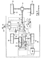
- Fig. 5 shows the drive train of a conventional vehicle.
- a drive motor 2, 10 is connected via a coupling device 12 to a transmission 14, the output shaft 16 is connected in the illustrated example via a propeller shaft 18 and a differential 20 with the rear wheels 22 of a vehicle.
- a clutch actuator 24 is provided for actuating the clutch device 12.
- actuators 26 and 28 are provided.
- the actuators 24, 26, 28 are controlled by an electronic control device 30 with a microprocessor and associated memories. Inputs of the electronic control device 30 are connected to positioners contained in the actuators and speed sensors 32 and 34 for detecting, for example, a rotational speed of a gear shaft and the rotational speed of the propeller shaft 34 and the output shaft 16. Further, an input of the controller 30 is connected to a position sensor 36 of a selector lever 38 for activating various programs of the controller 30.
- an engine control unit 40 To control the drive motor 10 is an engine control unit 40, whose inputs with a position sensor 42 for detecting the position of an accelerator pedal, a speed sensor 46 for detecting the rotational speed of the crankshaft of the internal combustion engine, a temperature sensor 48 for detecting an engine temperature, sensors 50 for detecting further operating parameters of Motors and a position sensor for detecting the position of an actuator 52 for a load actuator 54 of the drive motor 10 are connected. Further, sensors 54 for detecting the rotational speeds of the front wheels 56 and the rear wheels 22 may be provided, which are connected to the engine control unit 40.
- the engine control unit 40 is connected to the Transmission control device 30 via a data line, such as a CAN-BUS 58, connected, via which a data communication.
- a data line such as a CAN-BUS 58
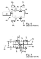
- FIG. 6 schematically shows the structure of the coupling device 12 and the transmission 14.
- An output shaft 58 of the drive motor 10 is rotatably connected to two parallel transmission branches 60 and 62, which are rotatably connected respectively via a gear unit 64 and 66 to the output shaft 16.
- the gear units 64 and 66 may be conventional transmissions whose gears are rotatably connected in a conventional manner via an actuator 68 and 70, respectively.
- the clutches K1 and K2 can be actuated by means of actuators 24 1 and 24 2 .
- Fig. 7 shows the structure of a Doppelkupplungs- or parallel transmission, which has a total of three shafts, namely two input shafts 72 and 74, which can be rotatably connected via different sets of wheels with one of the common output shaft 16.
- the wheelsets are in constant contact with each other.
- the wheels of the input shafts 72 and 74 can be synchronized in a conventional manner by means of axially displaceable on the shafts coupling members 76 with the shafts and brought into rotationally fixed engagement.
- an actuator 78 is provided with a selector member 80 and a switching member 82, wherein the selector, for example, from the actuator 26 (FIGS. Fig.
- the clutches K1 and K2 are on the input side in rotationally fixed engagement with the output shaft 58 of the drive motor.
- the clutches K1 and K2 are from the clutch actuators 24 1 and 24 2 ( Fig. 6 ).
- one of the gears of the transmission branch 62 can be switched with the clutch K2 open, so that by merely opening the clutch K1 and simultaneous closing of the clutch K2 a tensile force free translation change can be made from a gear of the transmission branch 60 to a gear of the transmission branch 62.
- This gear or gear ratio should be as comfortable as possible for the driver of a vehicle, depending on the position of the selector lever 38 in the control device 30th different programs can be activated, according to which the gear change as quickly as possible athletic, as soft and comfortable or otherwise optimized.
- the actuation of the clutches K1 and K2 and the load actuator of the drive motor 10 thus takes place according to programs that are stored, for example, in the controller 30, from where via the bus 58 and the controller 40 and the actuator 52 of the load actuator 53 can be actuated.
- the transmission-side half of the new clutch rotates with the speed of the transmission input shaft plus the slip speed, but the transmission-side half of the new clutch rotates at the speed of the transmission input shaft, is then reduced by a subsequent lowering of the engine torque below the clutch torque of the new clutch pulled down the engine speed to the speed of the newly effective transmission input shaft.
- Braking the engine adds additional torque derived from the energy stored in the flywheel of the engine and acting on the transmission output shaft via the transmission input shaft.
- the reduction of the engine torque corresponds to the torque contribution due to the deceleration of the engine, so that no additional torque is brought to the transmission output shaft by the deceleration of the engine.
- the new clutch is now fully closed and the engine torque is returned to its original value.
- From the DE 103 08 700 A1 is known to zoom at a traction-free ratio change of a parallel shift or dual-clutch transmission, the initially torque-transmitting clutch to its slip limit and to increase the engine torque for a short time, so that the torque-transmitting clutch slips with a reserve and the new clutch does not adhere to the transition from the "old" clutch to the "new” clutch.
- the DE 199 39 334 A1 is disclosed as the closest prior art and discloses the features of the preamble of claim 1. It discloses a dual-clutch transmission and method of shifting the dual-clutch transmission without interruption of traction. The switching operations are carried out by controlling and / or regulating the clutches and the drive motor.
- the invention has for its object to provide a method and an apparatus for its implementation, with which or a gear change a parallel shift transmission, in particular a traction upshift, under all conditions can be made as comfortable as possible.
- an implementation of the method according to the invention is such that the torque of the clutch transmitting the old transmission is continuously changed from about zero to a predetermined value during the gear ratio change to approximately zero and the torque of the clutch transmitting the new gear ratio is continuously changed.
- the load of the drive motor is advantageously precontrolled in accordance with the sum of the instantaneous torques that can be transmitted by the clutches.
- the load of the drive motor is advantageously controlled by means of a D-controller, to which the time derivative of the actual slip is supplied as an input variable.
- the load of the drive motor for keeping constant the slip of the clutches is alternatively or additionally controlled by means of a P-controller, which is fed as an input variable, the difference from the instantaneous slip and slip at the beginning of the ratio change.
- the clutch actuator 24 contains two actuators which can be controlled independently of one another by the control device 30 in accordance therewith and with which the two clutches K1 and K2 (FIG. Fig. 5 and 6 ) are independently operable in such a way that at each clutch a defined clutch torque is transferable.
- the slip of the clutches can be measured via their input speed (detected by the speed sensor 46) and the speeds of the output shafts 72 and 74 (FIG. Fig. 6 ), detected by the sensors 32, or from the rotational speed of the output shaft 16 (detected by the sensor 34) and the respective effective gears (known from the control device 30) are determined.
- the clutch of the old gear is opened and the clutch of the target gear (new clutch) is closed at a certain moment.
- the actual, effective on the vehicle translation translation or the gear change takes place.
- the torque acting on the output shaft 16 changes according to the gear ratio.
- the prerequisite for a smooth transition is that both clutches slip over the entire course.
- the clutch torques are controlled, whereas the engine torque is controlled.
- the control takes place such that the drive motor 10 by changing the position of its load actuator 53 on the output shaft 58 ( Fig. 5 ) emits a torque that leads to a slip of the controlled actuated clutches.
- the regulation of the position of the load actuator 53 and the torque of the output shaft 58 takes place under a pilot control, which is superimposed on the actual control.
- t phase is given a predetermined, for example, by the activated by means of the selector lever program certain period of time during which a ratio change occurs.
- the dashed line I of Fig. 1 indicates the pilot-controlled torque on the output shaft of the drive motor; the dashed-one-point curve II indicates the transferable from the old clutch torque. The dashed double-dotted curve III indicates the transferable from the new clutch torque.
- the torque of the old clutch is slightly lowered before the start of a gear change, so that the old clutch slips.
- This initial slip of the old clutch which can be specified in the program, is maintained at a constant value by changing the engine torque throughout the gear change, which slip applies to both the old clutch and the new clutch.
- the torque transmitted by the old clutch is lowered linearly from the beginning of the gear change until the end of the gear shift according to the predetermined time t phase of the gear change to a very small value.
- the transmittable by the new clutch torque is increased according to the line III preferably linearly controlled up to a final value at the end of the ratio change, wherein the transmittable at the end of the new clutch torque preferably behaves to the transmittable at the beginning of the ratio change of the old clutch torque like the initial gear ratio to the final gear ratio, ie, for example, in a Switzerlandrochscrien the final torque is so much greater than the initial torque, as at the same speed of the drive motor, the output shaft rotates faster in the shorter gear than in the longer gear.
- the result is the pilot straight line IV, which is equal to the sum of the momentarily transferable clutch torques, namely M Cl, Alt + M Cl, New .
- M Err is added, which is the clutch torque error at the old clutch at the beginning of the overlap that contains the friction and touch point errors and naturally drops to zero at the end of the gear change.
- M Err M Eng - M Cl, Alt - M Cl , New - M Dyn, Alt, Begin - M Acc.
- M Dyn, Alt, Begin is determined at the beginning of the translation change.
- M Err is a moment that applies only to the old clutch and is not transferable to the new one. Thus, M Err decreases to zero during the gear shift.
- the torque M Acc which decreases linearly during the ratio change, is added to the precontrol engine torque M Eng, pilot control .
- the time period t phase can be preset and remains constant during a ratio change.
- the dashed curve VI shows the course of the engine speed ⁇ Eng , the dotted line VI the speed ⁇ old of the "old” input shaft and the double-dotted line VII the speed ⁇ new of the "new" input shaft.
- Fig. 1 The basis of the Fig. 1 explained pilot control of the output torque from the drive motor is superimposed to maintain the slip of the clutches a scheme that contains a D-controller, which uses as an input the time derivative of the actual slip ⁇ Act .
- a P-controller is switched whose input contains the difference between the actual slip ⁇ Act and the slip at the beginning of the phase or the beginning of the ratio change ⁇ Anf .
- the job of the P-Regulator is to prevent the slippage from breaking down completely.
- the P controller is turned on only when the absolute amount of slip becomes smaller than the slip determined at the beginning of the speed change.
- K is a stored proportionality constant.
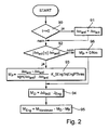
- step 92 In the event that the condition of step 92 is not present, the proportional engine torque is set to 0 in step 96 and the program immediately proceeds to step 94.
- the clutch torque of the old clutch (curve II) is linearly reduced until its complete opening.
- the overlap time or the duration of the gear ratio change is predetermined and depends, for example, on the particular driving program selected.
- the clutch torque of the new clutch is kept at 0 before a gear ratio change, which ensures that the clutch can react as quickly as possible to the torque request during the gear ratio change and a possible backlash in the transmission is overcome.
- Fig. 3 represent: the curve a) the driver command torque M FW , the curve b) the target torque M Cl, Alt, target the old clutch, the curve c) the actual torque M Cl, Alt, Is the old clutch, the curve d) the target torque M Cl, new, the new clutch and the curve e) the actual torque M Cl, New, is the new clutch.
- the parameters of the min function are determined experimentally and adapted to the respective vehicle.
- the larger of the two moments M ' Cl, New and M'' Cl, New is always used.
- the torque of the new clutch corresponds to the value of the driver's desired torque.
Claims (8)
- Procédé de commande d'un changement de rapport de transmission, en particulier du passage à un rapport supérieur, dans une transmission à rapports de transmission parallèles d'un véhicule, laquelle transmission à rapports de transmission parallèles présentant deux branches de transmission (60, 62) disposées en parallèle entre un arbre entraîné (58) d'un moteur d'entraînement (10) du véhicule et un arbre (16) de sortie de la transmission,
un arbre d'entrée (72, 74) de chaque branche de transmission pouvant être accouplé à l'arbre de sortie au moyen d'un embrayage (K1, K2) qui lui est associé et l'arbre d'entrée de chaque branche de la transmission pouvant engager à rotation solidaire l'arbre de sortie à au moins un rapport de transmission prédéterminé, de sorte que par ouverture d'un des embrayages et fermeture de l'autre embrayage, on puisse changer le rapport de transmission entre l'arbre entraîné et l'arbre de sortie sans interruption de la force de traction,
les couples qui peuvent être transmis par les embrayages pendant un changement de rapport de transmission étant modifiés sous contrôle prédéterminé et la charge du moteur d'entraînement (10) étant régulée de manière à maintenir un patinage prédéterminé des embrayages, un patinage prédéterminé étant avant le début du changement de rapport de transmission établi sur l'embrayage qui transférait l'ancien rapport de transmission, ce patinage étant maintenu pendant le changement de rapport de transmission,
caractérisé en ce que
les couples d'embrayage sont commandés et la charge du moteur d'entraînement (10) est régulée et
en ce que la régulation s'effectue de telle sorte que par modification de la position de son organe (53) de réglage de charge, le moteur d'entraînement (10) délivre à l'arbre entraîné (58) un couple qui conduit de manière contrôlée à un patinage des embrayages actionnés. - Procédé de commande d'un changement de rapport de transmission selon la revendication 1, dans lequel le couple de l'embrayage qui transférait l'ancien rapport de transmission est amené progressivement à environ zéro pendant le changement de rapport de transmission et le couple de l'embrayage qui transfère le nouveau rapport de transmission est amené progressivement d'environ zéro jusqu'à une valeur prédéterminée.
- Procédé de commande d'un changement de rapport de transmission selon la revendication 2, dans lequel la somme des couples qui peuvent être transférés par les deux embrayages pendant le changement de rapport de transmission se modifie progressivement depuis une valeur initiale jusqu'à une valeur finale, la valeur initiale présentant par rapport à la valeur finale sensiblement le même rapport que celui entre l'ancien rapport de transmission et le nouveau rapport de transmission.
- Procédé de commande d'un changement de rapport de transmission selon l'une des revendications 1 à 3, dans lequel la charge du moteur d'entraînement est pré-commandée en correspondance à la somme des couples instantanés qui peuvent être transmis par les embrayages.
- Procédé de commande d'un changement de rapport de transmission selon la revendication 4, dans lequel la pré-commande de la charge du moteur d'entraînement est de plus commandée en fonction d'une grandeur supplémentaire qui contient au moins l'une des grandeurs suivantes :- la fraction dynamique de l'accélération de l'arbre d'entrée qui transmet l'ancien rapport de transmission,- le couple qui résulte de la différence entre l'accélération de la vitesse de rotation du moteur d'entraînement et celle de l'arbre d'entrée qui transmet l'ancien rapport de transmission au début du changement de rapport de transmission et- l'erreur de couple d'embrayage sur l'embrayage qui transfère l'ancien rapport de transmission au début du changement de rapport de transmission.
- Procédé de commande d'un changement de rapport de transmission selon l'une des revendications 1 à 5, dans lequel la charge du moteur d'entraînement est régulée de manière à maintenir constant le patinage des embrayages à l'aide d'un régulateur D auquel la dérivée par rapport au temps du patinage effectif est apportée comme grandeur d'entrée.
- Procédé de commande d'un changement de rapport de transmission selon l'une des revendications 1 à 6, dans lequel la charge du moteur d'entraînement est régulée de manière à maintenir constant le patinage des embrayages à l'aide d'un régulateur P auquel la différence entre le patinage instantané et le patinage au début du changement de rapport de transmission est apportée comme grandeur d'entrée.
- Dispositif de commande d'un changement de rapport de transmission et en particulier du passage à un rapport de transmission plus élevé dans une transmission à rapports de transmission parallèles d'un véhicule automobile, laquelle transmission à rapports de transmission parallèles présentant deux branches de transmission (60, 62) disposées en parallèle entre un arbre entraîné (58) d'un moteur d'entraînement (10) du véhicule et un arbre (16) de sortie de la transmission,
un arbre d'entrée de chaque branche de transmission pouvant être accouplé à l'arbre de sortie au moyen d'un embrayage (K1, K2) qui lui est associé et l'arbre d'entrée de chaque branche de la transmission pouvant engager à rotation solidaire l'arbre de sortie à au moins un rapport de transmission prédéterminé, de sorte que par ouverture d'un des embrayages et fermeture de l'autre embrayage, on puisse changer le rapport de transmission entre l'arbre entraîné et l'arbre de sortie sans interruption de la force de traction, le dispositif contenant :- un dispositif (241) d'actionnement de l'embrayage de la première branche de la transmission,- un dispositif (242) d'actionnement de l'embrayage de la deuxième branche de la transmission,- un dispositif (52) d'actionnement d'un organe de réglage de la charge du moteur d'entraînement,- des dispositifs de détection qui détectent le patinage du premier embrayage et du deuxième embrayage et- un dispositif de commande (30) relié aux dispositifs d'actionnement et aux dispositifs de détection et qui commande le fonctionnement des dispositifs d'actionnement de manière à exécuter un procédé selon l'une des revendications 1 à 7.
Applications Claiming Priority (2)
| Application Number | Priority Date | Filing Date | Title |
|---|---|---|---|
| DE102004007101 | 2004-02-13 | ||
| DE102004007101 | 2004-02-13 |
Publications (3)
| Publication Number | Publication Date |
|---|---|
| EP1564446A2 EP1564446A2 (fr) | 2005-08-17 |
| EP1564446A3 EP1564446A3 (fr) | 2010-02-24 |
| EP1564446B1 true EP1564446B1 (fr) | 2012-03-14 |
Family
ID=34684038
Family Applications (1)
| Application Number | Title | Priority Date | Filing Date |
|---|---|---|---|
| EP05000775A Not-in-force EP1564446B1 (fr) | 2004-02-13 | 2005-01-15 | Méthode et dispostif de commande de changement de vitesse pour transmission véhiculaire à changement parallèle |
Country Status (7)
| Country | Link |
|---|---|
| US (1) | US7337050B2 (fr) |
| EP (1) | EP1564446B1 (fr) |
| JP (1) | JP4867054B2 (fr) |
| KR (1) | KR101238153B1 (fr) |
| CN (1) | CN100532173C (fr) |
| AT (1) | ATE549550T1 (fr) |
| DE (1) | DE102005001981A1 (fr) |
Families Citing this family (18)
| Publication number | Priority date | Publication date | Assignee | Title |
|---|---|---|---|---|
| DE102005022314A1 (de) * | 2005-05-10 | 2006-11-16 | Zf Friedrichshafen Ag | Verfahren zur Steuerung eines Getriebes eines Fahrzeugs |
| GB0609333D0 (en) | 2006-05-11 | 2006-06-21 | Zeroshift Ltd | Engagement member actuator control |
| GB0510129D0 (en) | 2005-05-18 | 2005-06-22 | Zeroshift Ltd | Sequential hub layout |
| JP4367399B2 (ja) * | 2005-10-21 | 2009-11-18 | トヨタ自動車株式会社 | 車両の駆動力制御装置 |
| DE102006024277A1 (de) * | 2006-05-24 | 2007-12-27 | Zf Friedrichshafen Ag | Verfahren und Vorrichtung zur Steuerung eines automatisierten Schaltgetriebes |
| WO2009054270A1 (fr) * | 2007-10-22 | 2009-04-30 | Komatsu Ltd. | Système et procédé de commande de sortie de moteur de véhicule de travail |
| US7985163B2 (en) * | 2007-12-13 | 2011-07-26 | Ford Global Technologies, Llc | Adaptive clutch torque control for a powershift transmission |
| JP5205408B2 (ja) * | 2010-03-24 | 2013-06-05 | 株式会社小松製作所 | 作業車両及び作業車両の制御方法 |
| US8682545B2 (en) * | 2010-06-15 | 2014-03-25 | Ford Global Technologies, Llc | Damping oscillations during a gear ratio change of a dual clutch powershift transmission |
| FR2964715B1 (fr) * | 2010-09-13 | 2012-08-31 | Renault Sas | Procede de rangement de rapports montant pour boite de vitesses automatique d'un vehicule automobile |
| GB201109100D0 (en) | 2011-05-27 | 2011-07-13 | Zeroshift Ltd | Transmission system |
| US8775044B2 (en) | 2011-06-08 | 2014-07-08 | Ford Global Technologies, Llc | Clutch torque trajectory correction to provide torque hole filling during a ratio upshift |
| CA2866935A1 (fr) | 2012-03-23 | 2013-09-26 | Pacific Rim Engineered Products (1987) Ltd. | Transmission de puissance a embrayage de type double avec voie de transmission de couple alternative offrant des rapports alternatifs |
| CN104380050B (zh) | 2012-03-23 | 2018-03-23 | 环太平洋工程产品(1987)有限公司 | 用于变速器的齿轮接合机构以及相关方法 |
| EP2937239B1 (fr) * | 2012-12-19 | 2018-09-12 | Volvo Truck Corporation | Dispositif de changement de vitesse pour véhicule |
| US9327733B2 (en) * | 2014-08-07 | 2016-05-03 | GM Global Technology Operations LLC | Method of controlling a vehicle during a clutch-to-clutch power upshift of a transmission |
| US9551415B2 (en) * | 2014-08-26 | 2017-01-24 | Ford Global Technologies, Llc | Output torque control method |
| US9551418B1 (en) * | 2015-07-10 | 2017-01-24 | Deere & Company | System and method for reducing engine flywheel power reduction while protecting drivetrain components |
Family Cites Families (22)
| Publication number | Priority date | Publication date | Assignee | Title |
|---|---|---|---|---|
| JPS5877138A (ja) * | 1981-11-04 | 1983-05-10 | Toyota Motor Corp | 自動変速機の変速制御方法 |
| JPS6189127A (ja) * | 1984-10-08 | 1986-05-07 | Nissan Motor Co Ltd | 自動変速機の変速シヨツク軽減装置 |
| JPH0721313B2 (ja) * | 1985-06-11 | 1995-03-08 | 三菱自動車工業株式会社 | 流体継手用クラッチの制御装置 |
| US4860607A (en) * | 1986-06-20 | 1989-08-29 | Toyota Jidosha Kabushiki Kaisha | Automatic transmission for automotive vehicle |
| US4790418A (en) * | 1987-04-30 | 1988-12-13 | Ford Motor Company | Transmission clutch loop transfer control |
| DE4204401A1 (de) * | 1992-02-14 | 1993-08-19 | Bosch Gmbh Robert | Einrichtung zur steuerung des abtriebsmoments eines automatischen schaltgetriebes |
| DE4333899A1 (de) * | 1993-10-05 | 1995-07-13 | Bosch Gmbh Robert | Verfahren zur Steuerung des Abtriebsmoments eines automatischen Schaltgetriebes |
| JP3706650B2 (ja) * | 1995-03-02 | 2005-10-12 | 本田技研工業株式会社 | 油圧作動式変速機の制御装置 |
| FR2732278B1 (fr) * | 1995-04-03 | 1997-06-20 | Magneti Marelli France | Systeme a boite de vitesses mecanique robotisee comprenant des moyens de commande perfectionnes a l'arret du vehicule |
| DE19631983C1 (de) * | 1996-08-08 | 1998-02-12 | Volkswagen Ag | Verfahren zum Schalten eines Doppelkupplungsgetriebes und Doppelkupplungsgetriebe mit Synchronisiereinrichtung |
| DE19939334A1 (de) * | 1999-08-19 | 2001-03-08 | Daimler Chrysler Ag | Verfahren zum Schalten eines Doppelkupplungsgetriebes und Doppelkupplungsgetriebe |
| DE10004530B4 (de) * | 2000-02-02 | 2012-11-15 | Volkswagen Ag | Verfahren zur Steuerung eines Doppelkupplungsgetriebes |
| JP2003522670A (ja) * | 2000-02-15 | 2003-07-29 | ルーク ラメレン ウント クツプルングスバウ ベタイリグングス コマンディートゲゼルシャフト | 変速機 |
| DE10122084A1 (de) * | 2000-05-17 | 2001-12-13 | Luk Lamellen & Kupplungsbau | Getriebe mit Kupplung sowie Verfahren zum Betreiben einer Kupplung |
| DE10160308A1 (de) | 2001-01-12 | 2002-07-18 | Zf Sachs Ag | Verfahren zum Betrieb eines eine Mehrfach-Kupplungseinrichtung und ein Lastschaltgetriebe aufweisenden Antriebsstrangs und derartiger Antriebsstrang mit entprechender Steuereinheit |
| US6463821B1 (en) * | 2001-06-29 | 2002-10-15 | Daimlerchrysler Corporation | Method of controlling a transmission having a dual clutch system |
| JP2003094987A (ja) * | 2001-09-20 | 2003-04-03 | Toyota Motor Corp | エンジンおよび変速機の制御装置 |
| JP3812432B2 (ja) * | 2001-12-10 | 2006-08-23 | 株式会社デンソー | 自動変速機の制御装置 |
| WO2003074312A2 (fr) * | 2002-03-07 | 2003-09-12 | Luk Lamellen Und Kupplungsbau Beteiligungs Kg | Procede de changement de vitesse dans une boite de vitesses a double embrayage |
| JP4034089B2 (ja) * | 2002-03-07 | 2008-01-16 | 株式会社日立製作所 | 自動変速機のクリープ制御装置及び方法 |
| DE10308700B4 (de) | 2002-03-07 | 2014-09-04 | Schaeffler Technologies Gmbh & Co. Kg | Verfahren zum Durchführen einer Hochschaltung von einem Anfangsgang in einen Zielgang bei dem Doppelkupplungsgetriebe eines Fahrzeuges |
| DE10390914D2 (de) * | 2002-03-07 | 2005-05-19 | Luk Lamellen & Kupplungsbau | Doppelkupplungsgetriebe und Verfahren zum Durchführen einer Schaltung bei einem Doppelkupplungsgetriebe |
-
2005
- 2005-01-15 AT AT05000775T patent/ATE549550T1/de active
- 2005-01-15 EP EP05000775A patent/EP1564446B1/fr not_active Not-in-force
- 2005-01-15 DE DE200510001981 patent/DE102005001981A1/de not_active Withdrawn
- 2005-02-04 KR KR1020050010301A patent/KR101238153B1/ko active IP Right Grant
- 2005-02-08 CN CNB2005100913133A patent/CN100532173C/zh not_active Expired - Fee Related
- 2005-02-11 US US10/906,276 patent/US7337050B2/en not_active Expired - Fee Related
- 2005-02-14 JP JP2005036872A patent/JP4867054B2/ja not_active Expired - Fee Related
Also Published As
| Publication number | Publication date |
|---|---|
| KR20060041679A (ko) | 2006-05-12 |
| CN1721248A (zh) | 2006-01-18 |
| US20050182544A1 (en) | 2005-08-18 |
| JP2005226836A (ja) | 2005-08-25 |
| JP4867054B2 (ja) | 2012-02-01 |
| EP1564446A3 (fr) | 2010-02-24 |
| ATE549550T1 (de) | 2012-03-15 |
| US7337050B2 (en) | 2008-02-26 |
| KR101238153B1 (ko) | 2013-02-27 |
| DE102005001981A1 (de) | 2005-09-01 |
| EP1564446A2 (fr) | 2005-08-17 |
| CN100532173C (zh) | 2009-08-26 |
Similar Documents
| Publication | Publication Date | Title |
|---|---|---|
| EP1564446B1 (fr) | Méthode et dispostif de commande de changement de vitesse pour transmission véhiculaire à changement parallèle | |
| DE112010002949B4 (de) | Verfahren und Vorrichtung zum Steuern eines Doppelkupplungsgetriebes | |
| EP1439087B1 (fr) | Procédé de commande et de régulation du couple moteur et du couple d'embrayage durant un changement de vitesse d'une transmission robotisée ou à double embrayage | |
| DE112013001042B4 (de) | Verfahren zur Ermittlung eines Tastpunkts | |
| DE10228709A1 (de) | Verfahren zum Adaptieren der Einstellung einer Kupplung in einem unkonventionellen Antriebsstrang eines Fahrzeugs | |
| WO2002094601A2 (fr) | Procede de commande de vehicules dotes d'un dispositif d'embrayage automatise | |
| WO2003086804A1 (fr) | Procede, dispositif et leur utilisation pour faire fonctionner un vehicule automobile | |
| DE10230612A1 (de) | Verfahren, Vorrichtung und deren Verwendung zum Betrieb eines Kraftfahrzeuges, insbesondere zum Verbessern eines Anfahrvorganges | |
| DE112012006767T5 (de) | Fahrzeuggetriebesteuerung | |
| DE19709417A1 (de) | Vorrichtung zur Ansteuerung eines Drehmomentübertragungssystems und eines Getriebes, sowie ein Verfahren hierfür | |
| EP2240709B1 (fr) | Dispositif et procede empechant le passage de rapports inadequats dans des transmissions automatiques de vehicules motorises | |
| DE19932755A1 (de) | Steuerungsvorrichtung | |
| DE102014208557B4 (de) | Verfahren zur Steuerung und/oder Regelung der Schaltung eines Doppelkupplungsgetriebes eines Kraftfahrzeugs | |
| EP1382479B1 (fr) | Méthode de démarrage d'un système de transmission de véhicule avec une boîte de vitesse à double embrayage | |
| WO2008104148A1 (fr) | Procédé et dispositif de commande des embrayages d'une boîte de vitesses à couplage parallèle lors d'un changement de vitesse | |
| EP1566560B1 (fr) | Procédé pour régler le point d'activation d'au moins un embrayage d'une boîte de vitesses automatisée et appareil, en particulier pour la réalisation du procédé | |
| DE102004033716A1 (de) | Verfahren zum Betrieb eines eine Mehrfach-Kupplungseinrichtung und ein Lastschaltgetriebe aufweisenden Antriebsstrangs und derartiger Antriebsstrang mit entsprechender Steuereinheit | |
| DE102005034525A1 (de) | Kraftfahrzeug-Getriebeeinrichtung sowie Verfahren zur Steuerung eines Kraftfahrzeuges, und insbesondere zur Steuerung einer Getriebeeinrichtung eines Kraftfahrzeuges | |
| DE10261723B4 (de) | Verfahren zur Adaptation einer Schaltkennlinie einer Lastschaltkupplung eines Kraftfahrzeuggetriebes | |
| AT508077B1 (de) | Verfahren zum betreiben eines ein lastschalt-wendegetriebe aufweisenden kraftfahrzeuges | |
| EP3760889A1 (fr) | Chaine cinématique d'un véhicule ainsi que procédé de fonctionnement d'une chaine cinématique d'un véhicule | |
| DE102021209152B3 (de) | Verfahren zur Steuerung eines Schaltvorganges | |
| DE10312397A1 (de) | Verfahren, Vorrichtung und deren Verwendung zum Betrieb eines Kraftfahrzeuge insbesondere zur Ansteuerung eines automatisierten Schaltgetriebes | |
| DE10322619A1 (de) | Automatisiertes Schaltgetriebe sowie Verfahren zum Betreiben einer Getriebeeinrichtung | |
| WO2004059195A1 (fr) | Procede et dispositif de controle d'erreur d'un dispositif de commande electronique d'une transmission automatique disposee dans la chaine cinematique d'un vehicule |
Legal Events
| Date | Code | Title | Description |
|---|---|---|---|
| PUAI | Public reference made under article 153(3) epc to a published international application that has entered the european phase |
Free format text: ORIGINAL CODE: 0009012 |
|
| AK | Designated contracting states |
Kind code of ref document: A2 Designated state(s): AT BE BG CH CY CZ DE DK EE ES FI FR GB GR HU IE IS IT LI LT LU MC NL PL PT RO SE SI SK TR |
|
| AX | Request for extension of the european patent |
Extension state: AL BA HR LV MK YU |
|
| PUAL | Search report despatched |
Free format text: ORIGINAL CODE: 0009013 |
|
| AK | Designated contracting states |
Kind code of ref document: A3 Designated state(s): AT BE BG CH CY CZ DE DK EE ES FI FR GB GR HU IE IS IT LI LT LU MC NL PL PT RO SE SI SK TR |
|
| AX | Request for extension of the european patent |
Extension state: AL BA HR LV MK YU |
|
| 17P | Request for examination filed |
Effective date: 20100824 |
|
| 17Q | First examination report despatched |
Effective date: 20100924 |
|
| AKX | Designation fees paid |
Designated state(s): AT BE BG CH CY CZ DE DK EE ES FI FR GB GR HU IE IS IT LI LT LU MC NL PL PT RO SE SI SK TR |
|
| R17C | First examination report despatched (corrected) |
Effective date: 20100930 |
|
| RAP1 | Party data changed (applicant data changed or rights of an application transferred) |
Owner name: SCHAEFFLER TECHNOLOGIES GMBH & CO. KG |
|
| 17Q | First examination report despatched |
Effective date: 20110311 |
|
| GRAP | Despatch of communication of intention to grant a patent |
Free format text: ORIGINAL CODE: EPIDOSNIGR1 |
|
| GRAS | Grant fee paid |
Free format text: ORIGINAL CODE: EPIDOSNIGR3 |
|
| GRAA | (expected) grant |
Free format text: ORIGINAL CODE: 0009210 |
|
| AK | Designated contracting states |
Kind code of ref document: B1 Designated state(s): AT BE BG CH CY CZ DE DK EE ES FI FR GB GR HU IE IS IT LI LT LU MC NL PL PT RO SE SI SK TR |
|
| RAP1 | Party data changed (applicant data changed or rights of an application transferred) |
Owner name: SCHAEFFLER TECHNOLOGIES AG & CO. KG |
|
| REG | Reference to a national code |
Ref country code: GB Ref legal event code: FG4D Free format text: NOT ENGLISH |
|
| REG | Reference to a national code |
Ref country code: AT Ref legal event code: REF Ref document number: 549550 Country of ref document: AT Kind code of ref document: T Effective date: 20120315 Ref country code: CH Ref legal event code: EP |
|
| REG | Reference to a national code |
Ref country code: IE Ref legal event code: FG4D Free format text: LANGUAGE OF EP DOCUMENT: GERMAN |
|
| REG | Reference to a national code |
Ref country code: DE Ref legal event code: R096 Ref document number: 502005012522 Country of ref document: DE Effective date: 20120503 |
|
| REG | Reference to a national code |
Ref country code: NL Ref legal event code: VDEP Effective date: 20120314 |
|
| PG25 | Lapsed in a contracting state [announced via postgrant information from national office to epo] |
Ref country code: LT Free format text: LAPSE BECAUSE OF FAILURE TO SUBMIT A TRANSLATION OF THE DESCRIPTION OR TO PAY THE FEE WITHIN THE PRESCRIBED TIME-LIMIT Effective date: 20120314 |
|
| LTIE | Lt: invalidation of european patent or patent extension |
Effective date: 20120314 |
|
| PG25 | Lapsed in a contracting state [announced via postgrant information from national office to epo] |
Ref country code: FI Free format text: LAPSE BECAUSE OF FAILURE TO SUBMIT A TRANSLATION OF THE DESCRIPTION OR TO PAY THE FEE WITHIN THE PRESCRIBED TIME-LIMIT Effective date: 20120314 Ref country code: GR Free format text: LAPSE BECAUSE OF FAILURE TO SUBMIT A TRANSLATION OF THE DESCRIPTION OR TO PAY THE FEE WITHIN THE PRESCRIBED TIME-LIMIT Effective date: 20120615 |
|
| PG25 | Lapsed in a contracting state [announced via postgrant information from national office to epo] |
Ref country code: CY Free format text: LAPSE BECAUSE OF FAILURE TO SUBMIT A TRANSLATION OF THE DESCRIPTION OR TO PAY THE FEE WITHIN THE PRESCRIBED TIME-LIMIT Effective date: 20120314 |
|
| PG25 | Lapsed in a contracting state [announced via postgrant information from national office to epo] |
Ref country code: PL Free format text: LAPSE BECAUSE OF FAILURE TO SUBMIT A TRANSLATION OF THE DESCRIPTION OR TO PAY THE FEE WITHIN THE PRESCRIBED TIME-LIMIT Effective date: 20120314 Ref country code: CZ Free format text: LAPSE BECAUSE OF FAILURE TO SUBMIT A TRANSLATION OF THE DESCRIPTION OR TO PAY THE FEE WITHIN THE PRESCRIBED TIME-LIMIT Effective date: 20120314 Ref country code: RO Free format text: LAPSE BECAUSE OF FAILURE TO SUBMIT A TRANSLATION OF THE DESCRIPTION OR TO PAY THE FEE WITHIN THE PRESCRIBED TIME-LIMIT Effective date: 20120314 Ref country code: IS Free format text: LAPSE BECAUSE OF FAILURE TO SUBMIT A TRANSLATION OF THE DESCRIPTION OR TO PAY THE FEE WITHIN THE PRESCRIBED TIME-LIMIT Effective date: 20120714 Ref country code: EE Free format text: LAPSE BECAUSE OF FAILURE TO SUBMIT A TRANSLATION OF THE DESCRIPTION OR TO PAY THE FEE WITHIN THE PRESCRIBED TIME-LIMIT Effective date: 20120314 Ref country code: SE Free format text: LAPSE BECAUSE OF FAILURE TO SUBMIT A TRANSLATION OF THE DESCRIPTION OR TO PAY THE FEE WITHIN THE PRESCRIBED TIME-LIMIT Effective date: 20120314 Ref country code: SI Free format text: LAPSE BECAUSE OF FAILURE TO SUBMIT A TRANSLATION OF THE DESCRIPTION OR TO PAY THE FEE WITHIN THE PRESCRIBED TIME-LIMIT Effective date: 20120314 |
|
| PG25 | Lapsed in a contracting state [announced via postgrant information from national office to epo] |
Ref country code: SK Free format text: LAPSE BECAUSE OF FAILURE TO SUBMIT A TRANSLATION OF THE DESCRIPTION OR TO PAY THE FEE WITHIN THE PRESCRIBED TIME-LIMIT Effective date: 20120314 Ref country code: PT Free format text: LAPSE BECAUSE OF FAILURE TO SUBMIT A TRANSLATION OF THE DESCRIPTION OR TO PAY THE FEE WITHIN THE PRESCRIBED TIME-LIMIT Effective date: 20120716 |
|
| PLBE | No opposition filed within time limit |
Free format text: ORIGINAL CODE: 0009261 |
|
| STAA | Information on the status of an ep patent application or granted ep patent |
Free format text: STATUS: NO OPPOSITION FILED WITHIN TIME LIMIT |
|
| PG25 | Lapsed in a contracting state [announced via postgrant information from national office to epo] |
Ref country code: DK Free format text: LAPSE BECAUSE OF FAILURE TO SUBMIT A TRANSLATION OF THE DESCRIPTION OR TO PAY THE FEE WITHIN THE PRESCRIBED TIME-LIMIT Effective date: 20120314 Ref country code: NL Free format text: LAPSE BECAUSE OF FAILURE TO SUBMIT A TRANSLATION OF THE DESCRIPTION OR TO PAY THE FEE WITHIN THE PRESCRIBED TIME-LIMIT Effective date: 20120314 |
|
| 26N | No opposition filed |
Effective date: 20121217 |
|
| PG25 | Lapsed in a contracting state [announced via postgrant information from national office to epo] |
Ref country code: IT Free format text: LAPSE BECAUSE OF FAILURE TO SUBMIT A TRANSLATION OF THE DESCRIPTION OR TO PAY THE FEE WITHIN THE PRESCRIBED TIME-LIMIT Effective date: 20120314 |
|
| REG | Reference to a national code |
Ref country code: DE Ref legal event code: R097 Ref document number: 502005012522 Country of ref document: DE Effective date: 20121217 |
|
| PG25 | Lapsed in a contracting state [announced via postgrant information from national office to epo] |
Ref country code: ES Free format text: LAPSE BECAUSE OF FAILURE TO SUBMIT A TRANSLATION OF THE DESCRIPTION OR TO PAY THE FEE WITHIN THE PRESCRIBED TIME-LIMIT Effective date: 20120625 |
|
| BERE | Be: lapsed |
Owner name: SCHAEFFLER TECHNOLOGIES A.G. & CO. KG Effective date: 20130131 |
|
| PG25 | Lapsed in a contracting state [announced via postgrant information from national office to epo] |
Ref country code: BG Free format text: LAPSE BECAUSE OF FAILURE TO SUBMIT A TRANSLATION OF THE DESCRIPTION OR TO PAY THE FEE WITHIN THE PRESCRIBED TIME-LIMIT Effective date: 20120614 |
|
| PG25 | Lapsed in a contracting state [announced via postgrant information from national office to epo] |
Ref country code: MC Free format text: LAPSE BECAUSE OF NON-PAYMENT OF DUE FEES Effective date: 20130131 |
|
| REG | Reference to a national code |
Ref country code: CH Ref legal event code: PL |
|
| GBPC | Gb: european patent ceased through non-payment of renewal fee |
Effective date: 20130115 |
|
| REG | Reference to a national code |
Ref country code: IE Ref legal event code: MM4A |
|
| PG25 | Lapsed in a contracting state [announced via postgrant information from national office to epo] |
Ref country code: BE Free format text: LAPSE BECAUSE OF NON-PAYMENT OF DUE FEES Effective date: 20130131 Ref country code: CH Free format text: LAPSE BECAUSE OF NON-PAYMENT OF DUE FEES Effective date: 20130131 Ref country code: LI Free format text: LAPSE BECAUSE OF NON-PAYMENT OF DUE FEES Effective date: 20130131 |
|
| PG25 | Lapsed in a contracting state [announced via postgrant information from national office to epo] |
Ref country code: GB Free format text: LAPSE BECAUSE OF NON-PAYMENT OF DUE FEES Effective date: 20130115 |
|
| PG25 | Lapsed in a contracting state [announced via postgrant information from national office to epo] |
Ref country code: IE Free format text: LAPSE BECAUSE OF NON-PAYMENT OF DUE FEES Effective date: 20130115 |
|
| REG | Reference to a national code |
Ref country code: AT Ref legal event code: MM01 Ref document number: 549550 Country of ref document: AT Kind code of ref document: T Effective date: 20130115 |
|
| REG | Reference to a national code |
Ref country code: DE Ref legal event code: R081 Ref document number: 502005012522 Country of ref document: DE Owner name: SCHAEFFLER TECHNOLOGIES AG & CO. KG, DE Free format text: FORMER OWNER: LUK LAMELLEN UND KUPPLUNGSBAU BETEILIGUNGS KG, 77815 BUEHL, DE Effective date: 20120314 Ref country code: DE Ref legal event code: R081 Ref document number: 502005012522 Country of ref document: DE Owner name: SCHAEFFLER TECHNOLOGIES AG & CO. KG, DE Free format text: FORMER OWNER: SCHAEFFLER TECHNOLOGIES AG & CO. KG, 91074 HERZOGENAURACH, DE Effective date: 20140213 Ref country code: DE Ref legal event code: R081 Ref document number: 502005012522 Country of ref document: DE Owner name: SCHAEFFLER TECHNOLOGIES GMBH & CO. KG, DE Free format text: FORMER OWNER: LUK LAMELLEN UND KUPPLUNGSBAU BETEILIGUNGS KG, 77815 BUEHL, DE Effective date: 20120314 Ref country code: DE Ref legal event code: R081 Ref document number: 502005012522 Country of ref document: DE Owner name: SCHAEFFLER TECHNOLOGIES GMBH & CO. KG, DE Free format text: FORMER OWNER: SCHAEFFLER TECHNOLOGIES AG & CO. KG, 91074 HERZOGENAURACH, DE Effective date: 20140213 |
|
| PG25 | Lapsed in a contracting state [announced via postgrant information from national office to epo] |
Ref country code: AT Free format text: LAPSE BECAUSE OF NON-PAYMENT OF DUE FEES Effective date: 20130115 |
|
| REG | Reference to a national code |
Ref country code: DE Ref legal event code: R081 Ref document number: 502005012522 Country of ref document: DE Owner name: SCHAEFFLER TECHNOLOGIES AG & CO. KG, DE Free format text: FORMER OWNER: SCHAEFFLER TECHNOLOGIES GMBH & CO. KG, 91074 HERZOGENAURACH, DE Effective date: 20150213 |
|
| PG25 | Lapsed in a contracting state [announced via postgrant information from national office to epo] |
Ref country code: TR Free format text: LAPSE BECAUSE OF FAILURE TO SUBMIT A TRANSLATION OF THE DESCRIPTION OR TO PAY THE FEE WITHIN THE PRESCRIBED TIME-LIMIT Effective date: 20120314 |
|
| PG25 | Lapsed in a contracting state [announced via postgrant information from national office to epo] |
Ref country code: LU Free format text: LAPSE BECAUSE OF NON-PAYMENT OF DUE FEES Effective date: 20130115 Ref country code: HU Free format text: LAPSE BECAUSE OF FAILURE TO SUBMIT A TRANSLATION OF THE DESCRIPTION OR TO PAY THE FEE WITHIN THE PRESCRIBED TIME-LIMIT; INVALID AB INITIO Effective date: 20050115 |
|
| REG | Reference to a national code |
Ref country code: FR Ref legal event code: PLFP Year of fee payment: 12 |
|
| REG | Reference to a national code |
Ref country code: FR Ref legal event code: PLFP Year of fee payment: 13 |
|
| REG | Reference to a national code |
Ref country code: FR Ref legal event code: PLFP Year of fee payment: 14 |
|
| PGFP | Annual fee paid to national office [announced via postgrant information from national office to epo] |
Ref country code: FR Payment date: 20210121 Year of fee payment: 17 |
|
| PGFP | Annual fee paid to national office [announced via postgrant information from national office to epo] |
Ref country code: DE Payment date: 20210319 Year of fee payment: 17 |
|
| REG | Reference to a national code |
Ref country code: DE Ref legal event code: R119 Ref document number: 502005012522 Country of ref document: DE |
|
| PG25 | Lapsed in a contracting state [announced via postgrant information from national office to epo] |
Ref country code: DE Free format text: LAPSE BECAUSE OF NON-PAYMENT OF DUE FEES Effective date: 20220802 |
|
| PG25 | Lapsed in a contracting state [announced via postgrant information from national office to epo] |
Ref country code: FR Free format text: LAPSE BECAUSE OF NON-PAYMENT OF DUE FEES Effective date: 20220131 |
|
| P01 | Opt-out of the competence of the unified patent court (upc) registered |
Effective date: 20230523 |