EP1561996A1 - Absperrvorrichtung für ein Gas führendes Rohr - Google Patents
Absperrvorrichtung für ein Gas führendes Rohr Download PDFInfo
- Publication number
- EP1561996A1 EP1561996A1 EP04026555A EP04026555A EP1561996A1 EP 1561996 A1 EP1561996 A1 EP 1561996A1 EP 04026555 A EP04026555 A EP 04026555A EP 04026555 A EP04026555 A EP 04026555A EP 1561996 A1 EP1561996 A1 EP 1561996A1
- Authority
- EP
- European Patent Office
- Prior art keywords
- shut
- flap
- pipe section
- butterfly valve
- sealing material
- Prior art date
- Legal status (The legal status is an assumption and is not a legal conclusion. Google has not performed a legal analysis and makes no representation as to the accuracy of the status listed.)
- Granted
Links
- 239000003566 sealing material Substances 0.000 claims abstract description 34
- 238000007789 sealing Methods 0.000 claims abstract description 26
- 239000002184 metal Substances 0.000 claims abstract description 7
- 230000002093 peripheral effect Effects 0.000 claims description 8
- 239000000463 material Substances 0.000 claims description 5
- 238000004873 anchoring Methods 0.000 claims description 3
- 239000007789 gas Substances 0.000 description 9
- 230000007704 transition Effects 0.000 description 5
- 230000000694 effects Effects 0.000 description 4
- 229920002943 EPDM rubber Polymers 0.000 description 2
- 238000001746 injection moulding Methods 0.000 description 2
- 229920001296 polysiloxane Polymers 0.000 description 2
- 230000005540 biological transmission Effects 0.000 description 1
- 238000001816 cooling Methods 0.000 description 1
- 230000001419 dependent effect Effects 0.000 description 1
- 238000006073 displacement reaction Methods 0.000 description 1
- 239000003517 fume Substances 0.000 description 1
- 238000010438 heat treatment Methods 0.000 description 1
- 238000002347 injection Methods 0.000 description 1
- 239000007924 injection Substances 0.000 description 1
- 239000000565 sealant Substances 0.000 description 1
- 229910001220 stainless steel Inorganic materials 0.000 description 1
- 239000010935 stainless steel Substances 0.000 description 1
- 238000009423 ventilation Methods 0.000 description 1
- 238000013022 venting Methods 0.000 description 1
Images


Classifications
-
- F—MECHANICAL ENGINEERING; LIGHTING; HEATING; WEAPONS; BLASTING
- F23—COMBUSTION APPARATUS; COMBUSTION PROCESSES
- F23L—SUPPLYING AIR OR NON-COMBUSTIBLE LIQUIDS OR GASES TO COMBUSTION APPARATUS IN GENERAL ; VALVES OR DAMPERS SPECIALLY ADAPTED FOR CONTROLLING AIR SUPPLY OR DRAUGHT IN COMBUSTION APPARATUS; INDUCING DRAUGHT IN COMBUSTION APPARATUS; TOPS FOR CHIMNEYS OR VENTILATING SHAFTS; TERMINALS FOR FLUES
- F23L13/00—Construction of valves or dampers for controlling air supply or draught
- F23L13/02—Construction of valves or dampers for controlling air supply or draught pivoted about a single axis but having not other movement
-
- F—MECHANICAL ENGINEERING; LIGHTING; HEATING; WEAPONS; BLASTING
- F23—COMBUSTION APPARATUS; COMBUSTION PROCESSES
- F23J—REMOVAL OR TREATMENT OF COMBUSTION PRODUCTS OR COMBUSTION RESIDUES; FLUES
- F23J11/00—Devices for conducting smoke or fumes, e.g. flues
- F23J11/12—Smoke conduit systems for factories or large buildings
-
- F—MECHANICAL ENGINEERING; LIGHTING; HEATING; WEAPONS; BLASTING
- F23—COMBUSTION APPARATUS; COMBUSTION PROCESSES
- F23L—SUPPLYING AIR OR NON-COMBUSTIBLE LIQUIDS OR GASES TO COMBUSTION APPARATUS IN GENERAL ; VALVES OR DAMPERS SPECIALLY ADAPTED FOR CONTROLLING AIR SUPPLY OR DRAUGHT IN COMBUSTION APPARATUS; INDUCING DRAUGHT IN COMBUSTION APPARATUS; TOPS FOR CHIMNEYS OR VENTILATING SHAFTS; TERMINALS FOR FLUES
- F23L11/00—Arrangements of valves or dampers after the fire
- F23L11/005—Arrangements of valves or dampers after the fire for closing the flue during interruption of burner function
Definitions
- the present invention relates to a shut-off device for a gas leading Pipe, in particular for an exhaust pipe of a fireplace, comprising a housed in a pipe section of the pipe and a for Pipe section axis substantially orthogonal pivot axis between a shut-off and an open position swiveling butterfly valve from a sheet metal, in particular sheet metal, which in the shut-off position at least approximately orthogonal to the pipe section axis lies and at its perennialsssaum with a surface area on the inner circumference the pipe section sealingly cooperates.
- shut-off device Such a shut-off device is known from DE 196 03 615 A1.
- This shut-off device has a butterfly valve, which in an exhaust pipe is arranged, which connects a fireplace with a fireplace.
- the Butterfly valve is used to close and open the exhaust pipe. To it is coupled with a motor drive, by means of which they are between its shut-off position and its open position is pivotable. While Operation of the fireplace should the butterfly valve in its open position so that the fumes produced by the fireplace in the fireplace can deduct. If the fireplace is not in operation, the butterfly valve should normally closed, u. a. thus a cooling of the room, in which the fireplace is placed, is prevented.
- the object of the present invention is a shut-off device specify the type mentioned above with good sealing effect, with simple means can be realized and works reliably and permanently.
- the butterfly valve on perforated with holes around its peripheral seam, which penetrates with sealing material are.
- the sealing material can in particular Silicone, EPDM and / or PUDF included and by injection molding be upset.
- the shape of the seal assembly in suitable and designed in a simple manner and to the shape of the butterfly valve and the pipe section. For example, you can be provided to increase the sealing effect sealing lips, which are in the shut-off position in particular to a from the inner circumference of the pipe section create radially projecting flange, which serves as an abutment used for the butterfly valve. The shape of this flange must thus not subject to great precision.
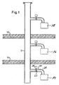
- Fig. 1 shows an example of the use of the shut-off device according to the invention in the exhaust gas discharge system of a modern heating system.
- floor shelves 10a and 10b of a building shown schematically.
- a Abgasab 2015weg 12 passes through the Floors 10a, 10b.
- the Abgasab 2015weg 12 is here as a classic fireplace trained.
- In the individual floors of the building is to the fireplace 12 each have a fireplace 14, 16 and 18 connected. Every fireplace 14, 16 and 18 may be associated with a respective blower (not shown), which expels the exhaust gases towards the fireplace 12.
- the fireplaces 14, 16 and 18 may be identical. The following is an example of the Connection of the fireplace 14 to the chimney 12 further described.
- the fireplace 14 is connected via an exhaust pipe 20 to the chimney 12.
- a butterfly valve 22 is provided, which around a pipe axis orthogonal to the exhaust pipe axis between a the flow cross-section of the tube 20 occluding shut-off and an opening position releasing the flow path is.
- a connection path for exhaust gases between the fireplace 14 and the Chimney 12 can thus be made or broken as needed.
- a motor 26 is provided which is mounted outside the tube 20 and a sealing through the pipe wall Guided motor shaft has, where the butterfly valve is held.
- Fig. 1 the butterfly valve 22 is shown in its open position.
- Fig. 2 shows schematically a first embodiment of the invention Shut-off device in a longitudinal sectional view of the exhaust pipe 20.
- the butterfly valve 22 is arranged in a pipe section 28, the butterfly valve 22 is here in its shut-off position.
- the pipe section 28 and the butterfly valve 22 are formed of a metal sheet, advantageously from a relatively thin stainless steel sheet.
- a radially inwardly extending Flange 29 by narrowing the diameter of the pipe section 28 is formed.
- the constriction is a simple way producible constriction of the pipe.
- the butterfly valve 22 is disc-shaped and at two folds 64 and 66th bent. As a result, a first flap area 32 and a second flap area 34 formed parallel and - related to the axis of the Pipe section 28 in Fig. 2 - axially offset from each other.
- the Butterfly valve 22 has between the two fold lines 64, 66 a light obliquely extending flap area 62, the two flap areas 32, 34 connects and the axial displacement of the two flap areas 32, 34 bridged.
- In the area of the crease 64 is a short shaft approach 42 attached to the butterfly valve 22, which via an opening from the pipe section 28 protrudes and the shaft of the motor 26 is associated.
- the connection point between the pipe section 28 and the shaft extension 42 In the area of this opening is sealed, so that no exhaust gases escape can.
- the shaft extension 42 defines the orthogonal for the butterfly valve 22 to the pipe section axis extending pivot axis fixed to the the butterfly valve 22 by about 90 ° between the shut-off and the open position can be pivoted.
- the two flap areas 32, 34 are each at the peripheral edge with a elastomeric sealing material 36 of silicone, EPDM or PUDF coated.
- This sealing material 36 is at the peripheral edge on both Flap surface sides of the flap areas 32, 34 and on the narrow side applied to the flap circumference, preferably in an injection molding process. Due to the bends of the butterfly valve 22 at the folds 64, 66, the sealing material 36 on the two flap areas 32, 34th the flange 29 in the shut-off position of the butterfly valve 22 of opposite Touch axial sides.
- the flange 29 serves as a seal counter-stop for the sealing material 36 of the two flap regions 32, 34. The joints between the flange 29 and the sealing material 36 are well sealed with the shut-off valve 22 closed.
- Fig. 3 shows the shut-off device according to the first embodiment 2 in its open position.
- the butterfly valve 22 is complete the sealing material 36 against the shut-off by about 90 ° pivoted the pivot axis. Exhaust gases can shut off the device happen.
- the shut-off device is with a plan view of the closed Shut-off valve in the axial direction of the pipe section 28 shown.
- a holder 60 for the motor 26 and possibly a transmission appropriate.
- the butterfly valve 22 is here on one side, by means of the shaft approach 42, at a first bearing 68 on the pipe section 28 and stored at a second bearing point 70 on the holder 60. Due to the staggered arrangement of the flap portions 32, 34 is the sealing material 36 at the first flap portion 32 located here below partially through the Flush 29 concealed.
- the edge of the sealing material 36 on the narrow side the flap circumference at the flap area 32 is as a semicircular arc indicated.
- the flange 29 in turn is partially through the one up here located second flap portion 34 and the sealing material applied thereto 36 hidden.
- the course of the hidden flange 29 at the upper inner peripheral surface of the pipe section 28 is indicated by a dashed line Semicircular arc indicated.
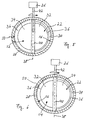
- Fig. 5 shows schematically a second embodiment of the invention Shut-off device.
- the butterfly valve 22 is located in their shut-off position. It is a cut pipe section 28 of the exhaust pipe 20 in its axial flow direction from the hearth 14 to the chimney 12 is shown.
- the butterfly valve 22 has a round cross-section and a disc shape through two opposing flap surface sides and one at the flap perimeter perpendicular to the two Flap face sides extending narrow side 50 is limited.
- the butterfly valve 22 is orthogonal to the axis of the pipe section 28.
- FIG. 2 shows the top view of a first flap surface side 52.
- the dashed line Semicircular arc on the left side of the butterfly valve 22 indicates its edge at the transition of the first flap surface side 52 to the narrow side 50 on.
- the butterfly valve 22 has an orthogonal to the pipe axis section Shaft 40, which defines a pivot axis 38.
- the shaft 40 divided the butterfly valve 22 in the first flap portion 32 and the second Flap area 34 and is at its two ends in the pipe section 28th stored.
- the shaft extension 42 is attached, which has a Opening protrudes from the pipe section 28 and in the adjustment 26th empties.
- the joint between the pipe section 28 and the Shaft 42 in the area of this opening is sealed, so no Exhaust gases can escape.
- the adjusting means 26 serves for pivoting the butterfly valve 22 about the pivot axis 38th
- the butterfly valve 22 is at its peripheral edge with elastomeric sealing material 36 provided.
- the sealing material covers the flap circumference the narrow side 50 and in each case a narrow strip of the edge regions the two flap surface sides 52, 54 and is at the perennialsssaum attached.
- the pipe section 28 has an inner circumferential surface 56, on which a radial inwardly extending first flange portion 30 and second Flange portion 31 (Fig. 6) are formed.
- the flange portions 30, 31 For example, by locally narrowing the diameter of the Pipe section or by a Flanscheinsatz of metal or possibly out be formed elastomeric sealing material. So that the butterfly valve 22 can fit snugly against the two flange portions 30, 31 can this by the width of the butterfly valve 22 and the width of the flap surface sides 52, 54 attached sealing material 36 axially against each other be offset.
- the sealing material 36 is sufficient in the present Embodiment on the flap surface sides 52, 54 radially further inside as the two flange portions 30, 31.
- FIG. 6 shows the top view of the second flap surface side 54.
- the dashed Semicircular arc on the left side of the butterfly valve 22 indicates its edge at the transition of the second flap surface side 54 to the narrow side 50 am Flap circumference on.
- the second flange portion 31 shown on the right side.
- Fig. 7 shows the shut-off device according to the second embodiment in her open position.
- the butterfly valve 22 is opposite to her Position pivoted in accordance with FIG. 5 by 90 °.
- Those of the in operation fireplace 14 exhaust gases generated by the pipe in the Pull off the chimney 12.
- the coated by the sealing material 36 narrow side 50 at the flap circumference and the edges of the transitions to the flap surface sides 52, 54 are indicated by dashed lines.
- Fig. 8 shows the top view of the first flap surface side 52 of the butterfly valve 22 without applied sealing material 36.
- the butterfly valve 22 holes 44 are inserted into the sheet material, which serve to anchor the sealing material 36. That advantageously Injection molded sealant 36 penetrates these holes 44 in particular completely and depends advantageously with the applied on the perennialsssaum the flap surface sides 52, 54 Seal material 36 integrally together. This can be a achieve secure attachment of the sealing material 36.
- FIG. 9 is a section of a preferred variant of the butterfly valve 22 shown.
- the sealing material 36 additionally has a first sealing lip here 46 and a second sealing lip 48, which provides an additional sealing effect guarantee.
- the first sealing lip 46 extends on the second Flap area 34, starting from the sealing material 36 in the edge region the transition from the narrow side 50 at the flap circumference to the flap surface side 54 obliquely to the flap surface side 54 existing Seal material 36.
- the second sealing lip 48 extends on the first flap region 32, starting from the sealing material 36 in the edge region the transition from the narrow side 50 at the flap circumference to the Flap face 52 obliquely to the flap surface side 52 existing Seal material 36.
- the sealing lips 46, 48 In the shut-off position of the butterfly valve 22 are the sealing lips 46, 48 with opposite axial sides of the Flange portions 30, 31 in contact.
- the first sealing lip 46 touches the in Direction of the fireplace 14-facing side of the flange 31 and the second sealing lip 48 touches the facing in the direction of the chimney 12 side flange area 30.
- the illustrated dimensions of the butterfly valve 22 are not to scale. In particular, the lips 46, 48 in various be implemented alternative forms and configurations.
- FIGS. 2 to 4 may be integral have formed from the elastomeric sealing material 36 shaped sealing lips.
- a shut-off device according to the invention is not for use in Limited exhaust systems. It can e.g. alternatively in a ventilation system or a venting system and the like. Use find.
Landscapes
- Engineering & Computer Science (AREA)
- Mechanical Engineering (AREA)
- General Engineering & Computer Science (AREA)
- Chemical & Material Sciences (AREA)
- Combustion & Propulsion (AREA)
- Architecture (AREA)
- Lift Valve (AREA)
- Exhaust Silencers (AREA)
Abstract
Description
- Fig. 1
- eine Skizze zur Erläuterung eines Anwendungsbeispiels erfindungsgemäßer Absperrvorrichtungen in einem mehrstöckigen Gebäude mit separaten Feuerstätten in den Stockwerken,
- Fig. 2
- eine schematische Darstellung eines ersten Ausführungsbeispiels der Absperrvorrichtung mit einer geschlossenen, in einem Rohrabschnitt angeordneten Absperrklappe in einer Schnittdarstellung mit der in Fig. 4 bei II-II angedeuteten Schnittebene,
- Fig. 3
- die Absperrvorrichtung gemäß der Fig. 2 in ihrer geöffneten Stellung in einer entsprechenden Schnittdarstellung,
- Fig. 4
- eine schematische Darstellung des Ausführungsbeispiels der Absperrvorrichtung betrachtet in axialer Richtung des Rohrabschnittes,
- Fig. 5
- eine schematische Darstellung eines zweiten Ausführungsbeispiels der Absperrvorrichtung mit einer geschlossenen, in einem Rohrabschnitt angeordneten Absperrklappe betrachtet in axialer Richtung des Rohrabschnittes,
- Fig. 6
- die Absperrvorrichtung gemäß Fig. 5 betrachtet in entgegengesetzter axialer Richtung des Rohrabschnittes,
- Fig. 7
- die Absperrvorrichtung gemäß Fig. 5 in ihrer geöffneten Stellung,
- Fig. 8
- die Absperrklappe mit Verankerungslöchern und
- Fig. 9
- eine Darstellung eines Ausführungsbeispiels einer Absperrklappe nach der Erfindung mit Dichtlippen.
Claims (7)
- Absperrvorrichtung für ein Gas führendes Rohr, insbesondere für ein Abgasrohr (20) einer Feuerstätte (14), umfassend eine in einem Rohrabschnitt (28) des Rohres untergebrachte und um eine zur Rohrabschnittsachse im Wesentlichen orthogonale Schwenkachse (38) zwischen einer Absperrstellung und einer Öffnungsstellung schwenkbare Absperrklappe (22) aus einem Blech, insbesondere Metallblech, welche in der Absperrstellung zumindest näherungsweise orthogonal zur Rohrabschnittsachse liegt und an ihrem Umfangssaum mit einem Flächenbereich am Innenumfang (56) des Rohrabschnittes (28) dichtend zusammenwirkt,
dadurch gekennzeichnet, dass
die Absperrklappe (22) an ihrem Umfangssaum mit einem daran fixierten und eine Dichtungsanordnung bildenden elastomeren Dichtungsmaterial (36) präpariert ist. - Absperrvorrichtung nach Anspruch 1, dadurch gekennzeichnet, dass sich das Dichtungsmaterial (36) am Klappenumfang über die Schmalseite (50) der Absperrklappe (22) hinweg von einer Klappenflächenseite (52) zur anderen Klappenflächenseite (54) erstreckt.
- Absperrvorrichtung nach Anspruch 1 oder 2, dadurch gekennzeichnet, dass das Blechmaterial der Absperrklappe (22) an deren Umfangssaum mit Verankerungslöchern (44) für das elastomere Dichtungsmaterial (36) perforiert ist, wobei die Perforationen von dem vorzugsweise im Spritzgussverfahren aufgetragenen elastomeren Dichtungsmaterial (36) abdichtend durchsetzt sind.
- Absperrvorrichtung nach Anspruch 2 oder 3, dadurch gekenn zeichnet, dass das zumindest in einem Bereich des Umfangssaums der Absperrklappe (22) auf den einander entgegengesetzten Klappenflächenseiten (52, 54) vorhandene Dichtungsmaterial (36) mit dem die jeweiligen Verankerungslöcher (44) durchsetzenden Dichtungsmaterial (36) integral zusammenhängt.
- Absperrvorrichtung nach einem der vorhergehenden Ansprüche, dadurch gekennzeichnet, dass die Dichtungsanordnung wenigstens eine Dichtlippe (46, 48) aufweist, die in der Absperrstellung der Absperrklappe (22) den Flächenbereich am Innenumfang (56) des Rohrabschnittes (28) beaufschlagt.
- Absperrvorrichtung nach einem der vorhergehenden Ansprüche, dadurch gekennzeichnet, dass der Rohrabschnitt (28) einen an seinem Innenumfang (56) radial nach innen abstehenden, insbesondere durch eine lokale Durchmesserverengung des Rohrabschnittes (28) gebildeten Flansch (29, 30, 31) aufweist, mit dem die Dichtungsanordnung in der Absperrstellung der Absperrklappe (22) abdichtend in Berührung steht.
- Absperrvorrichtung nach Anspruch 6, dadurch gekennzeichnet, dass die Schwenkachse (38) der Absperrklappe (22) und der Flansch (29, 30, 31) zumindest näherungsweise orthogonal zur Achse des Rohrabschnittes (28) verlaufen und die Schwenkachse (38) die Absperrklappe (22) in zwei Klappenbereiche (32, 34) unterteilt, deren jeder eine Dichtlippe (46, 48) der Dichtungsanordnung aufweist und die in der Absperrstellung der Absperrklappe (22) mit entgegengesetzten axialen Seiten des Flansches (29, 30, 31) vermittels der jeweiligen Dichtlippe (46, 48) in Berührung stehen.
Applications Claiming Priority (2)
| Application Number | Priority Date | Filing Date | Title |
|---|---|---|---|
| DE202004001919U | 2004-02-09 | ||
| DE200420001919 DE202004001919U1 (de) | 2004-02-09 | 2004-02-09 | Absperrvorrichtung für ein Gas führendes Rohr |
Publications (2)
| Publication Number | Publication Date |
|---|---|
| EP1561996A1 true EP1561996A1 (de) | 2005-08-10 |
| EP1561996B1 EP1561996B1 (de) | 2012-10-03 |
Family
ID=34673317
Family Applications (1)
| Application Number | Title | Priority Date | Filing Date |
|---|---|---|---|
| EP20040026555 Expired - Lifetime EP1561996B1 (de) | 2004-02-09 | 2004-11-09 | Absperrvorrichtung für ein Gas führendes Rohr |
Country Status (2)
| Country | Link |
|---|---|
| EP (1) | EP1561996B1 (de) |
| DE (1) | DE202004001919U1 (de) |
Cited By (2)
| Publication number | Priority date | Publication date | Assignee | Title |
|---|---|---|---|---|
| DE102011083127A1 (de) | 2011-09-21 | 2013-03-21 | Kutzner + Weber Gmbh | Absperrvorrichtung für ein Rohr |
| US11549415B2 (en) * | 2018-07-06 | 2023-01-10 | Faurecia Korea Ltd. | Valve assembly for vehicle exhaust system |
Families Citing this family (1)
| Publication number | Priority date | Publication date | Assignee | Title |
|---|---|---|---|---|
| DE102007062813B4 (de) * | 2007-12-21 | 2009-11-12 | Khs Ag | Trennwand, insbesondere zur Einhausung von Verpackungsmaschinen für Lebensmittel |
Citations (5)
| Publication number | Priority date | Publication date | Assignee | Title |
|---|---|---|---|---|
| DE8523605U1 (de) | 1985-08-16 | 1985-10-24 | Max Blank GmbH, 8821 Westheim | Verschlußrohr für eine Kamin-Frischluftzufuhr |
| DE3617510A1 (de) | 1985-10-19 | 1987-04-23 | Horst Linz | Kesselanlage mit einer luft-drosselklappe |
| DE4015584A1 (de) | 1990-05-15 | 1991-11-21 | Stober & Morlock | Rauchgasklappenanordnung |
| DE19603615A1 (de) | 1996-02-01 | 1997-08-07 | Kutzner & Weber Gmbh | Abgasabführsystem für gebäudeinstallierte Feuerstätten |
| EP1462722A2 (de) | 2003-03-25 | 2004-09-29 | Kutzner + Weber GmbH | Zugregler |
Family Cites Families (3)
| Publication number | Priority date | Publication date | Assignee | Title |
|---|---|---|---|---|
| DE19918128A1 (de) * | 1999-04-21 | 2000-10-26 | Dieter Moellmann | Absperrklappe für Rohrleitungen und Verfahren zur Herstellung derselben |
| DE10102398A1 (de) * | 2001-01-19 | 2002-07-25 | Zimmer Ag | Verschlusskörper zum Verschließen einer Rohrleitung und Verfahren hierzu |
| DE10132194C1 (de) * | 2001-07-03 | 2002-07-25 | Warex Valve Gmbh | Absperrorgan in einer Rohrleitung für Medien mit hohen Temperaturen |
-
2004
- 2004-02-09 DE DE200420001919 patent/DE202004001919U1/de not_active Expired - Lifetime
- 2004-11-09 EP EP20040026555 patent/EP1561996B1/de not_active Expired - Lifetime
Patent Citations (5)
| Publication number | Priority date | Publication date | Assignee | Title |
|---|---|---|---|---|
| DE8523605U1 (de) | 1985-08-16 | 1985-10-24 | Max Blank GmbH, 8821 Westheim | Verschlußrohr für eine Kamin-Frischluftzufuhr |
| DE3617510A1 (de) | 1985-10-19 | 1987-04-23 | Horst Linz | Kesselanlage mit einer luft-drosselklappe |
| DE4015584A1 (de) | 1990-05-15 | 1991-11-21 | Stober & Morlock | Rauchgasklappenanordnung |
| DE19603615A1 (de) | 1996-02-01 | 1997-08-07 | Kutzner & Weber Gmbh | Abgasabführsystem für gebäudeinstallierte Feuerstätten |
| EP1462722A2 (de) | 2003-03-25 | 2004-09-29 | Kutzner + Weber GmbH | Zugregler |
Cited By (2)
| Publication number | Priority date | Publication date | Assignee | Title |
|---|---|---|---|---|
| DE102011083127A1 (de) | 2011-09-21 | 2013-03-21 | Kutzner + Weber Gmbh | Absperrvorrichtung für ein Rohr |
| US11549415B2 (en) * | 2018-07-06 | 2023-01-10 | Faurecia Korea Ltd. | Valve assembly for vehicle exhaust system |
Also Published As
| Publication number | Publication date |
|---|---|
| EP1561996B1 (de) | 2012-10-03 |
| DE202004001919U1 (de) | 2005-06-23 |
Similar Documents
| Publication | Publication Date | Title |
|---|---|---|
| DE102012101322B4 (de) | Turbolader | |
| DE69301463T2 (de) | Auspuffregelventil für brennkraftmaschine | |
| DE10031991B4 (de) | Luftklappe | |
| DE102016117801A1 (de) | Element einer Abgasleitung mit einem Ventil mit zusätzlichen Anschlägen | |
| DE102011077766A1 (de) | Betätigungseinrichtung für ein Abgasstrom-Steuerelement eines Abgasturboladers | |
| DE19500475A1 (de) | Absperr- oder Drosselventil mit drehbarer Ventilklappe | |
| EP1835238B1 (de) | Luftkanal mit schwerkraftbetätigter Rückschlagklappe | |
| EP1493951A2 (de) | Klappenventil | |
| EP3430250A1 (de) | Ventilvorrichtung für einen turbolader | |
| EP2020544B1 (de) | Ventil, insbesondere Abgasrückführventil | |
| DE202019101676U1 (de) | Ventil für eine Abgasleitung | |
| DE102008034341A1 (de) | Doppelklappenventil | |
| EP1835239B1 (de) | Rückschlagklappenvorrichtung | |
| EP1561996A1 (de) | Absperrvorrichtung für ein Gas führendes Rohr | |
| EP2489914B1 (de) | Zuluft-Wanddurchführung | |
| DE19512874B4 (de) | Drosselklappenstutzen | |
| DE102006032584A1 (de) | Walzenschieberanordnung | |
| EP1573240B1 (de) | Ventil | |
| DE3111188C2 (de) | ||
| DE102006017213A1 (de) | Metallische Flachdichtung mit zerbrechlichen Verbindungsabschnitten | |
| EP1308676A2 (de) | Backofentür | |
| AT412415B (de) | Lüftungs-, insbesondere abluftjalousie | |
| DE3002626A1 (de) | Dichtungsvorrichtung zum abdichten zweier raeume unterschiedlichen druckes | |
| WO2003095815A1 (de) | Klappenventil für luftansaugkanal einer brennkraftmaschine | |
| DE2923885A1 (de) | Drehklappen-absperrventil |
Legal Events
| Date | Code | Title | Description |
|---|---|---|---|
| PUAI | Public reference made under article 153(3) epc to a published international application that has entered the european phase |
Free format text: ORIGINAL CODE: 0009012 |
|
| AK | Designated contracting states |
Kind code of ref document: A1 Designated state(s): AT BE BG CH CY CZ DE DK EE ES FI FR GB GR HU IE IS IT LI LU MC NL PL PT RO SE SI SK TR |
|
| AX | Request for extension of the european patent |
Extension state: AL HR LT LV MK YU |
|
| 17P | Request for examination filed |
Effective date: 20051216 |
|
| AKX | Designation fees paid |
Designated state(s): AT BE BG CH CY CZ DE DK EE ES FI FR GB GR HU IE IS IT LI LU MC NL PL PT RO SE SI SK TR |
|
| 17Q | First examination report despatched |
Effective date: 20110401 |
|
| GRAP | Despatch of communication of intention to grant a patent |
Free format text: ORIGINAL CODE: EPIDOSNIGR1 |
|
| GRAS | Grant fee paid |
Free format text: ORIGINAL CODE: EPIDOSNIGR3 |
|
| GRAA | (expected) grant |
Free format text: ORIGINAL CODE: 0009210 |
|
| AK | Designated contracting states |
Kind code of ref document: B1 Designated state(s): AT BE BG CH CY CZ DE DK EE ES FI FR GB GR HU IE IS IT LI LU MC NL PL PT RO SE SI SK TR |
|
| REG | Reference to a national code |
Ref country code: GB Ref legal event code: FG4D Free format text: NOT ENGLISH |
|
| REG | Reference to a national code |
Ref country code: AT Ref legal event code: REF Ref document number: 578153 Country of ref document: AT Kind code of ref document: T Effective date: 20121015 Ref country code: CH Ref legal event code: NV Representative=s name: E. BLUM & CO. AG PATENT- UND MARKENANWAELTE VSP Ref country code: CH Ref legal event code: EP |
|
| REG | Reference to a national code |
Ref country code: IE Ref legal event code: FG4D Free format text: LANGUAGE OF EP DOCUMENT: GERMAN |
|
| REG | Reference to a national code |
Ref country code: DE Ref legal event code: R096 Ref document number: 502004013788 Country of ref document: DE Effective date: 20121129 |
|
| REG | Reference to a national code |
Ref country code: NL Ref legal event code: T3 |
|
| PG25 | Lapsed in a contracting state [announced via postgrant information from national office to epo] |
Ref country code: SI Free format text: LAPSE BECAUSE OF FAILURE TO SUBMIT A TRANSLATION OF THE DESCRIPTION OR TO PAY THE FEE WITHIN THE PRESCRIBED TIME-LIMIT Effective date: 20121003 |
|
| PG25 | Lapsed in a contracting state [announced via postgrant information from national office to epo] |
Ref country code: IS Free format text: LAPSE BECAUSE OF FAILURE TO SUBMIT A TRANSLATION OF THE DESCRIPTION OR TO PAY THE FEE WITHIN THE PRESCRIBED TIME-LIMIT Effective date: 20130203 Ref country code: FI Free format text: LAPSE BECAUSE OF FAILURE TO SUBMIT A TRANSLATION OF THE DESCRIPTION OR TO PAY THE FEE WITHIN THE PRESCRIBED TIME-LIMIT Effective date: 20121003 Ref country code: ES Free format text: LAPSE BECAUSE OF FAILURE TO SUBMIT A TRANSLATION OF THE DESCRIPTION OR TO PAY THE FEE WITHIN THE PRESCRIBED TIME-LIMIT Effective date: 20130114 Ref country code: SE Free format text: LAPSE BECAUSE OF FAILURE TO SUBMIT A TRANSLATION OF THE DESCRIPTION OR TO PAY THE FEE WITHIN THE PRESCRIBED TIME-LIMIT Effective date: 20121003 |
|
| BERE | Be: lapsed |
Owner name: KUTZNER + WEBER G.M.B.H. Effective date: 20121130 |
|
| PG25 | Lapsed in a contracting state [announced via postgrant information from national office to epo] |
Ref country code: PT Free format text: LAPSE BECAUSE OF FAILURE TO SUBMIT A TRANSLATION OF THE DESCRIPTION OR TO PAY THE FEE WITHIN THE PRESCRIBED TIME-LIMIT Effective date: 20130204 Ref country code: GR Free format text: LAPSE BECAUSE OF FAILURE TO SUBMIT A TRANSLATION OF THE DESCRIPTION OR TO PAY THE FEE WITHIN THE PRESCRIBED TIME-LIMIT Effective date: 20130104 Ref country code: PL Free format text: LAPSE BECAUSE OF FAILURE TO SUBMIT A TRANSLATION OF THE DESCRIPTION OR TO PAY THE FEE WITHIN THE PRESCRIBED TIME-LIMIT Effective date: 20121003 Ref country code: CY Free format text: LAPSE BECAUSE OF FAILURE TO SUBMIT A TRANSLATION OF THE DESCRIPTION OR TO PAY THE FEE WITHIN THE PRESCRIBED TIME-LIMIT Effective date: 20121003 |
|
| PG25 | Lapsed in a contracting state [announced via postgrant information from national office to epo] |
Ref country code: EE Free format text: LAPSE BECAUSE OF FAILURE TO SUBMIT A TRANSLATION OF THE DESCRIPTION OR TO PAY THE FEE WITHIN THE PRESCRIBED TIME-LIMIT Effective date: 20121003 Ref country code: DK Free format text: LAPSE BECAUSE OF FAILURE TO SUBMIT A TRANSLATION OF THE DESCRIPTION OR TO PAY THE FEE WITHIN THE PRESCRIBED TIME-LIMIT Effective date: 20121003 Ref country code: BG Free format text: LAPSE BECAUSE OF FAILURE TO SUBMIT A TRANSLATION OF THE DESCRIPTION OR TO PAY THE FEE WITHIN THE PRESCRIBED TIME-LIMIT Effective date: 20130103 Ref country code: SK Free format text: LAPSE BECAUSE OF FAILURE TO SUBMIT A TRANSLATION OF THE DESCRIPTION OR TO PAY THE FEE WITHIN THE PRESCRIBED TIME-LIMIT Effective date: 20121003 Ref country code: CZ Free format text: LAPSE BECAUSE OF FAILURE TO SUBMIT A TRANSLATION OF THE DESCRIPTION OR TO PAY THE FEE WITHIN THE PRESCRIBED TIME-LIMIT Effective date: 20121003 |
|
| PLBE | No opposition filed within time limit |
Free format text: ORIGINAL CODE: 0009261 |
|
| STAA | Information on the status of an ep patent application or granted ep patent |
Free format text: STATUS: NO OPPOSITION FILED WITHIN TIME LIMIT |
|
| REG | Reference to a national code |
Ref country code: IE Ref legal event code: MM4A |
|
| PG25 | Lapsed in a contracting state [announced via postgrant information from national office to epo] |
Ref country code: RO Free format text: LAPSE BECAUSE OF FAILURE TO SUBMIT A TRANSLATION OF THE DESCRIPTION OR TO PAY THE FEE WITHIN THE PRESCRIBED TIME-LIMIT Effective date: 20121003 Ref country code: BE Free format text: LAPSE BECAUSE OF NON-PAYMENT OF DUE FEES Effective date: 20121130 |
|
| 26N | No opposition filed |
Effective date: 20130704 |
|
| PG25 | Lapsed in a contracting state [announced via postgrant information from national office to epo] |
Ref country code: IE Free format text: LAPSE BECAUSE OF NON-PAYMENT OF DUE FEES Effective date: 20121109 |
|
| REG | Reference to a national code |
Ref country code: DE Ref legal event code: R097 Ref document number: 502004013788 Country of ref document: DE Effective date: 20130704 |
|
| PG25 | Lapsed in a contracting state [announced via postgrant information from national office to epo] |
Ref country code: TR Free format text: LAPSE BECAUSE OF FAILURE TO SUBMIT A TRANSLATION OF THE DESCRIPTION OR TO PAY THE FEE WITHIN THE PRESCRIBED TIME-LIMIT Effective date: 20121003 Ref country code: MC Free format text: LAPSE BECAUSE OF NON-PAYMENT OF DUE FEES Effective date: 20121130 |
|
| PG25 | Lapsed in a contracting state [announced via postgrant information from national office to epo] |
Ref country code: LU Free format text: LAPSE BECAUSE OF NON-PAYMENT OF DUE FEES Effective date: 20121109 |
|
| PG25 | Lapsed in a contracting state [announced via postgrant information from national office to epo] |
Ref country code: HU Free format text: LAPSE BECAUSE OF FAILURE TO SUBMIT A TRANSLATION OF THE DESCRIPTION OR TO PAY THE FEE WITHIN THE PRESCRIBED TIME-LIMIT Effective date: 20041109 |
|
| PGFP | Annual fee paid to national office [announced via postgrant information from national office to epo] |
Ref country code: GB Payment date: 20141119 Year of fee payment: 11 Ref country code: FR Payment date: 20141119 Year of fee payment: 11 |
|
| PGFP | Annual fee paid to national office [announced via postgrant information from national office to epo] |
Ref country code: NL Payment date: 20141119 Year of fee payment: 11 |
|
| PGFP | Annual fee paid to national office [announced via postgrant information from national office to epo] |
Ref country code: IT Payment date: 20141128 Year of fee payment: 11 |
|
| GBPC | Gb: european patent ceased through non-payment of renewal fee |
Effective date: 20151109 |
|
| PG25 | Lapsed in a contracting state [announced via postgrant information from national office to epo] |
Ref country code: IT Free format text: LAPSE BECAUSE OF NON-PAYMENT OF DUE FEES Effective date: 20151109 |
|
| REG | Reference to a national code |
Ref country code: NL Ref legal event code: MM Effective date: 20151201 |
|
| REG | Reference to a national code |
Ref country code: FR Ref legal event code: ST Effective date: 20160729 |
|
| PG25 | Lapsed in a contracting state [announced via postgrant information from national office to epo] |
Ref country code: NL Free format text: LAPSE BECAUSE OF NON-PAYMENT OF DUE FEES Effective date: 20151201 |
|
| PG25 | Lapsed in a contracting state [announced via postgrant information from national office to epo] |
Ref country code: GB Free format text: LAPSE BECAUSE OF NON-PAYMENT OF DUE FEES Effective date: 20151109 |
|
| PG25 | Lapsed in a contracting state [announced via postgrant information from national office to epo] |
Ref country code: FR Free format text: LAPSE BECAUSE OF NON-PAYMENT OF DUE FEES Effective date: 20151130 |
|
| PGFP | Annual fee paid to national office [announced via postgrant information from national office to epo] |
Ref country code: CH Payment date: 20191121 Year of fee payment: 16 Ref country code: AT Payment date: 20191121 Year of fee payment: 16 |
|
| REG | Reference to a national code |
Ref country code: CH Ref legal event code: PL |
|
| REG | Reference to a national code |
Ref country code: AT Ref legal event code: MM01 Ref document number: 578153 Country of ref document: AT Kind code of ref document: T Effective date: 20201109 |
|
| PG25 | Lapsed in a contracting state [announced via postgrant information from national office to epo] |
Ref country code: LI Free format text: LAPSE BECAUSE OF NON-PAYMENT OF DUE FEES Effective date: 20201130 Ref country code: AT Free format text: LAPSE BECAUSE OF NON-PAYMENT OF DUE FEES Effective date: 20201109 Ref country code: CH Free format text: LAPSE BECAUSE OF NON-PAYMENT OF DUE FEES Effective date: 20201130 |
|
| PGFP | Annual fee paid to national office [announced via postgrant information from national office to epo] |
Ref country code: DE Payment date: 20231031 Year of fee payment: 20 |
|
| REG | Reference to a national code |
Ref country code: DE Ref legal event code: R071 Ref document number: 502004013788 Country of ref document: DE |