EP1561925A2 - Zusammenbau der elektrischen Geräte eines Motorrads - Google Patents
Zusammenbau der elektrischen Geräte eines Motorrads Download PDFInfo
- Publication number
- EP1561925A2 EP1561925A2 EP05100805A EP05100805A EP1561925A2 EP 1561925 A2 EP1561925 A2 EP 1561925A2 EP 05100805 A EP05100805 A EP 05100805A EP 05100805 A EP05100805 A EP 05100805A EP 1561925 A2 EP1561925 A2 EP 1561925A2
- Authority
- EP
- European Patent Office
- Prior art keywords
- capacitor
- regulator
- electrical devices
- crankcase
- fuel injection
- Prior art date
- Legal status (The legal status is an assumption and is not a legal conclusion. Google has not performed a legal analysis and makes no representation as to the accuracy of the status listed.)
- Granted
Links
- 239000003990 capacitor Substances 0.000 claims abstract description 109
- 230000001105 regulatory effect Effects 0.000 claims abstract description 9
- 239000000446 fuel Substances 0.000 claims description 50
- 238000002347 injection Methods 0.000 claims description 45
- 239000007924 injection Substances 0.000 claims description 45
- 238000011144 upstream manufacturing Methods 0.000 claims description 6
- 230000000087 stabilizing effect Effects 0.000 claims description 5
- 229920001971 elastomer Polymers 0.000 abstract description 15
- 239000005060 rubber Substances 0.000 abstract description 15
- 239000003570 air Substances 0.000 description 23
- 238000010438 heat treatment Methods 0.000 description 5
- 238000001816 cooling Methods 0.000 description 3
- 239000002828 fuel tank Substances 0.000 description 3
- 230000005484 gravity Effects 0.000 description 3
- XEEYBQQBJWHFJM-UHFFFAOYSA-N Iron Chemical compound [Fe] XEEYBQQBJWHFJM-UHFFFAOYSA-N 0.000 description 2
- 230000003247 decreasing effect Effects 0.000 description 2
- 238000010586 diagram Methods 0.000 description 2
- 238000003780 insertion Methods 0.000 description 2
- 230000037431 insertion Effects 0.000 description 2
- 238000009434 installation Methods 0.000 description 2
- 239000012080 ambient air Substances 0.000 description 1
- 238000005452 bending Methods 0.000 description 1
- 239000012530 fluid Substances 0.000 description 1
- 238000009499 grossing Methods 0.000 description 1
- 239000011810 insulating material Substances 0.000 description 1
- 229910052742 iron Inorganic materials 0.000 description 1
- 229910001234 light alloy Inorganic materials 0.000 description 1
- 238000000034 method Methods 0.000 description 1
- 230000000149 penetrating effect Effects 0.000 description 1
- 238000000746 purification Methods 0.000 description 1
- 238000003466 welding Methods 0.000 description 1
Images


Classifications
-
- F—MECHANICAL ENGINEERING; LIGHTING; HEATING; WEAPONS; BLASTING
- F02—COMBUSTION ENGINES; HOT-GAS OR COMBUSTION-PRODUCT ENGINE PLANTS
- F02M—SUPPLYING COMBUSTION ENGINES IN GENERAL WITH COMBUSTIBLE MIXTURES OR CONSTITUENTS THEREOF
- F02M35/00—Combustion-air cleaners, air intakes, intake silencers, or induction systems specially adapted for, or arranged on, internal-combustion engines
- F02M35/10—Air intakes; Induction systems
- F02M35/10242—Devices or means connected to or integrated into air intakes; Air intakes combined with other engine or vehicle parts
- F02M35/10249—Electrical or electronic devices fixed to the intake system; Electric wiring
-
- F—MECHANICAL ENGINEERING; LIGHTING; HEATING; WEAPONS; BLASTING
- F02—COMBUSTION ENGINES; HOT-GAS OR COMBUSTION-PRODUCT ENGINE PLANTS
- F02B—INTERNAL-COMBUSTION PISTON ENGINES; COMBUSTION ENGINES IN GENERAL
- F02B63/00—Adaptations of engines for driving pumps, hand-held tools or electric generators; Portable combinations of engines with engine-driven devices
- F02B63/02—Adaptations of engines for driving pumps, hand-held tools or electric generators; Portable combinations of engines with engine-driven devices for hand-held tools
-
- F—MECHANICAL ENGINEERING; LIGHTING; HEATING; WEAPONS; BLASTING
- F02—COMBUSTION ENGINES; HOT-GAS OR COMBUSTION-PRODUCT ENGINE PLANTS
- F02B—INTERNAL-COMBUSTION PISTON ENGINES; COMBUSTION ENGINES IN GENERAL
- F02B63/00—Adaptations of engines for driving pumps, hand-held tools or electric generators; Portable combinations of engines with engine-driven devices
- F02B63/04—Adaptations of engines for driving pumps, hand-held tools or electric generators; Portable combinations of engines with engine-driven devices for electric generators
-
- F—MECHANICAL ENGINEERING; LIGHTING; HEATING; WEAPONS; BLASTING
- F02—COMBUSTION ENGINES; HOT-GAS OR COMBUSTION-PRODUCT ENGINE PLANTS
- F02M—SUPPLYING COMBUSTION ENGINES IN GENERAL WITH COMBUSTIBLE MIXTURES OR CONSTITUENTS THEREOF
- F02M35/00—Combustion-air cleaners, air intakes, intake silencers, or induction systems specially adapted for, or arranged on, internal-combustion engines
- F02M35/16—Combustion-air cleaners, air intakes, intake silencers, or induction systems specially adapted for, or arranged on, internal-combustion engines characterised by use in vehicles
- F02M35/162—Motorcycles; All-terrain vehicles, e.g. quads, snowmobiles; Small vehicles, e.g. forklifts
Definitions
- the present invention relates to arrangement of electrical devices of saddle-ride type vehicles.
- Some saddle-ride type vehicles such as motorcycles adopt a structure that electric power generated by an AC generator built in a crankcase of an engine is stored in a battery through a regulator for voltage regulation. It is known that the regulator is mounted on an air cleaner in order to shorten the cable between the AC generator and the regulator (see Patent JP-A No.247181/1988).
- a batteryless power supply circuit which directly uses electric power from the AC generator for various types of electrical devices such as an ignition device without using a battery is also publicly known.
- the use of a capacitor for stable power supply to various types of electrical devices is also known (see Patent JP-Y No.15833/1995).
- the AC generator is built in the engine crankcase and the distance to the air cleaner located above and behind the crankcase is slightly long and, because the regulator is located in a higher position of the vehicle, the vehicle's center of gravity is high. Therefore, there has been demand for an arrangement that the regulator is located in a lower position than the air cleaner and its distance to the AC generator is minimized.
- the present invention has an object to meet this demand.
- the invention of Claim 1 concerning the arrangement of electrical devices in a saddle-ride type vehicle with an engine having a crankcase extending in the longitudinal direction of a vehicle body, a cylinder located before the crankcase and extending almost upward, a cylinder head located above the cylinder, and an AC generator built in the crankcase, is characterized in that a regulator for regulating output voltage of the AC generator is located behind the cylinder and on the top surface of the crankcase.
- the invention of Claim 2 is as described in Claim 1, a capacitor for stabilizing the voltage regulated by the regulator and supplying power to various electrical devices being located near the regulator.
- the invention of Claim 3 is as described in Claim 1, a mounting stay for holding the regulator being fitted through a heat-insulating member on the top surface of the crankcase.
- the invention of Claim 4 is as described in Claim 3, a mounting stay for holding the regulator being fitted through a heat-insulating member on the top surface of the crankcase and a capacitor for stabilizing the voltage regulated by the regulator and supplying power to various electrical devices being fitted through a heat-insulating member to the mounting stay.
- the invention of Claim 5 is as described in Claim 2 or 4, a fuel injection system being fitted to an engine air intake system extending behind the cylinder head and this fuel injection system being electromagnetically driven using power supplied from the capacitor for fuel injection.
- the invention of Claim 6 is as described in Claim 5, the engine air intake system at least comprising a throttle body connected upstream of an air intake duct of the cylinder head and incorporating a throttle valve, and a connecting tube connected upstream of it, and the regulator being inclined down backward and the capacitor being located above the regulator and behind and below the throttle body.
- the invention of Claim 7 is as described in Claim 5 or 6, the capacitor being divided into a second capacitor for supplying power to the fuel injection system and a first capacitor for supplying power to various electrical devices other than the fuel injection system and the second capacitor beingg located nearer to the vehicle front than the first capacitor.
- the regulator since the regulator is held on the top surface of the crankcase behind the cylinder, the cable from the AC generator, often built in the front part of the crankcase, to the regulator is shortened and power loss is reduced.
- the regulator since the regulator is located on the back of the crankcase, the vehicle's center of gravity is low and mass concentration is achieved.
- the front of the regulator in the traveling direction is covered by the cylinder and the crankcase and its bottom is covered by the crankcase, so the regulator is effectively protected from scattering stones or the like.
- the capacitor since the capacitor is located above the regulator inclined backward and behind and below the throttle body which is relatively large in the air intake system, it can be easily mounted even when it is a large-size capacitor with a large capacity. Therefore, even when the batteryless type is adopted, layout for the capacitor is easy. Also, because the regulator is inclined backward, latitude is wide in the arrangement of a connecting tube connected upstream of the throttle body.
- an exclusive capacitor for the fuel injection system since an exclusive capacitor for the fuel injection system is provided, the fuel injection system is driven more stably and the engine's startability and the vehicle's drivability are improved. Also, since the capacitor is divided into two capacitors, a capacitor for supplying power to the fuel injection system and a capacitor for supplying power to other electrical devices, the size of each capacitor can be decreased. Besides, since one capacitor is on the front side and the other is on the back side, latitude in the layout for the engine air intake system is wide. Moreover, since the exclusive capacitor for the fuel injection system is on the front side, the cable between the fuel injection system and the exclusive capacitor can be shortened.
- a motorcycle is an example of a saddle-ride type vehicle.
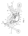
- Figure 1 is a side view of this motorcycle. 1 represents a front wheel; 2 a front fork; 3 a head pipe; 4 a handlebar; 5 a body frame; 6 a fuel tank; 7 a seat; 8 a rear frame; 9 a rear wheel; and 10 an engine.
- the body frame 5 includes: a pair of main frames 11 (left and right) located above the engine 10 and sloping down backward; a down frame 12 sloping down from the head pipe 3 to the front of the engine 10; a pair of pivot frames 13 (left and right) sloping down from the rear ends of the main frames 11, where the pivot frames 13 swingably support the front end of the rear frame 8 through their pivot shafts.
- the engine 10 is a water-cooled 4-cycle engine which is cooled by a radiator 14 supported by the down frame. It has a crankcase 15, a cylinder 16 protruding upward on it front side and a cylinder 17 located above it and is supported by the body frame 5.
- FIG 2 is an enlarged view of the key part of Figure 1.
- a cooling fan 14a for the radiator 14 is located in front of the cylinder head 17.
- An exhaust pipe 18 once extends forward from the front face of the cylinder head 17 and then bends and extends backward and connects to a muffler 19 at its rear end.
- An air intake duct which opens on the back side of the cylinder head 17 is connected with a throttle body 20 and an electronic fuel injection system 21.
- the throttle body 20 incorporates a throttle valve and is supplied with clean air through a connecting tube 23 from an air cleaner 22 located behind it.
- the air cleaner 22 takes in ambient air downward through an intake 22a which lies under the seat 7 with its opening inclined facing upward.
- the throttle body 20 and air cleaner 22 constitute an engine air intake system.
- the electronic fuel injection system 21 is supplied with fuel from the fuel tank 6 where fuel is supplied to the air intake duct through electromagnetic drive.
- crankcase 15, cylinder 16, cylinder head 17 and main frame 11 constitute a virtually triangular space S and this space is used for arrangement of a regulator 24, a first capacitor 25a and a second capacitor 25b. These are held on the top surface of the crankcase 15 behind the cylinder 16 by an electrical device mounting stay 26.
- the electrical device mounting stay 26 is detachably fitted to bosses 27 and 28 from above with bolts. 29a and 29b represent relays which are held on the front of the electrical device mounting stay 26 in front of the regulator 24.
- the electrical device mounting stay 26 is supported in a way that it is inclined down backward in the front-back (longitudinal) direction where the regulator 24 lies longitudinally when viewed sideways.
- alternate current from an AC generator 30 built in the front part of the crankcase 15 is used and the power circuit is of the batteryless type which uses no battery.
- the AC generator 30 is connected through an electric cable 31a to the regulator 24 and alternate current from the AC generator is rectified into direct current by the regulator 24; and after its voltage is regulated, it is sent to the first capacitor 25a and the second capacitor 25b through cables 31b and 31c. It is smoothed by these capacitors.
- the first capacitor 25a supplies power for various electrical devices such as ignition power for a spark plug 32 in the cylinder head 17.
- 33a represents a cable which connects the first capacitor 25a and an ignition coil 42
- 33b represents a cable which connects the ignition coil 42 and the spark plug 32.
- the ignition coil 42 is supported at its top and bottom by a stay 12a provided on the bottom of the down frame 12.
- the first capacitor 25a supplies power through the relays 29a and 29b to other electrical devices.
- the second capacitor 25b exclusively supplies power through a cable 34 to the fuel injection system 21.
- numeral 35 represents a rear cushion, mounted vertically, which connects the upper end of a pivot frame 13 and a cushion ring 8a located before and below a rear frame 8.
- 36 represents a front mount; 37 an engine hanger; 38 an upper mount located between the lower part of the engine hanger and the cylinder head; and 39 a rear mount located between the rear lower part of the crankcase 15 and the bottom of the pivot frame 13. The engine is held on the body frame 5 at these three points.
- Numeral 40 represents a secondary air valve for exhaust emission purification. It is supported by a gusset 41 connecting the front of the main frame 11 and the top of the down frame 12 and located before and obliquely above an exhaust port which is connected with the exhaust pipe 18 of the cylinder head 17, or near the exhaust port.
- Figure 3 is a plan view of the key part of the vehicle body above the engine and the paired left and right main frames 11 are pipes made of a light alloy whose cross section is a vertically long rectangle. Their rear portions expand to the left and right and the throttle body 20 lies between them.
- the connecting tube 23, extending backward, is curved to the left of the vehicle body in order to escape from the rear cushion 35 behind the throttle body 20 and, beside the rear cushion 35, connected with the front of the air cleaner 22 extended from behind.
- C represents the centerline of the vehicle body.
- FIG 4 is an enlarged side view which shows an area where electrical devices are mounted.
- the electrical device mounting stay 26 is fitted onto the bosses 27 and 28 integral with the top surface of the crankcase 15, through heat-insulating rubber 43 which also serves as a known vibration-isolating mount, using bolts 44, so that it is mounted on the top surface of the crankcase 15 in a vibration-isolating and heat-insulating manner.
- the stay is inclined down backward, where the angle with respect to a horizontal line H parallel to the ground is expressed by ⁇ .
- the regulator 24 has many fins 24a so that it can be efficiently air-cooled.
- the first and second capacitors 25a and 25b arranged back and front are rubber-mounted on the capacitor holders 46 for the electrical device mounting stay 26 through heat-insulating rubbers 45 respectively.
- Each heat-insulating rubber 45 is a band portion integral with the periphery of the case for the first capacitor 25a or second capacitor 25b and the capacitor holder 46 is inserted into it to support the electrical device mounting stay 26 in a vibration-insolating manner.
- the first and second capacitors 25a and 25b are each cylindrical and arranged back and front independently from each other with their axes along the vehicle body transverse direction.
- the front one is the second capacitor 25b, dedicated to injection, which supplies power to the fuel injection system 21.
- the rear one is the first capacitor 25b which is used for other electrical devices and supplies power to electrical devices other than the fuel injection system 21.
- the second capacitor 25b intended for injection only, is exposed above the regulator 24 and below the main frame 11 when viewed sideways while the first capacitor 25a, intended for the other electrical devices, partially overlaps the main frame 11 and lies inside the main frame 11 when viewed sideways.
- Figure 5 is an enlarged plan view which shows an area where electrical devices are mounted. These electrical devices lie between the left and right main frames 11.
- the relays 29a and 29b are supported by support pieces 48a and 48b of relay holders 48 which deviate toward the right side of the vehicle body and extend forward from the electrical device mounting stay 26.
- the rear end of the electrical device mounting stay 26 is fitted onto the two (left and right) bosses 28 through holes 54a in the two (left and right) bosses 54 using bolts.
- Numeral 24b represents a connector provided on the front face of the regulator 24.
- 51 represents a reservoir tank stay for supporting a reservoir tank for a rear brake fluid which protrudes upward from a main body 50 integrally with it.
- the reservoir tank 52 is held on the electrical device mounting stay 26 by bolting the bottom of the reservoir tank 52 to a weld nut 51a at the upper end.
- Figure 6 shows the structure of the first capacitor 25a where the heat-insulating rubber 45 extends sideways on the side face of the case integrally and this heat-insulating rubber 45 has a slit 45a penetrating the first capacitor 25a along its axial direction.
- a cord tube 49 extends from the center of a circular end face of the first capacitor 25a, and wires 49a lie inside the tube. The wires 49a are connected with other wires such as cable 33a by a coupler 49b provided at an end of the cord tube 49.
- the first capacitor 25a Since the first capacitor 25a is used for power supply as a substitute for a battery, its capacity is large: for example, approximately 10000 ⁇ F. Therefore, its size is relatively large.
- the second capacitor 25b has a similar structure and its heat-insulating rubber 45 has the same structure.
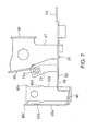
- FIG. 7 is a side view of the electrical device mounting stay 26.
- the electrical device mounting stay 26 is made by press-forming an iron plate or the like or a similar method. It comprises the following components continuously and integrally molded from one plate: a main body 50, a reservoir tank stay 51, a capacitor holder 47, a relay holder 48 and so on.
- the reservoir tank stay 51 and the capacitor holder 47 are made by bending the left and right sides of the main body 50 upward.
- the upper part of the capacitor holder 50 has an insert 46 in a curved form which extends above the main body 50 from right to left. These inserts 46 are provided at two points (a front point and a rear point) which correspond to the first capacitor 25a and the second capacitor 25b. Each insert 46 is designed to engage with the slit 45a ( Figure 6) provided in the heat-insulating rubber 45 of the corresponding capacitor.
- Tongue-shaped inserts 48a and 48b are standing upward, with an angle difference of 90 degrees between them, before and on the right of the relay holder 48 and respectively inserted into the slit of the holder 29c integral with the relay 29a and relay 29b ( Figure 4) from below and engaged to support the relay 29a and relay 29b.
- These slits are formed in the same way as the slits 45a of the capacitors.
- the inserts 48a and 48b are integrated with the relay holder 48 by welding their bottoms onto it.
- the tongue-shaped insert 48b has engaging projections 48c and 48d which are vertically spaced. This spacing coincides with the insertion (vertical) width of the slit of the band-shaped holder 29c integral with the corresponding relay. The engaging projections 48c and 48d protrude beyond the slit width.
- the structure of the insert 48b is the same as that of the insert 48a.
- the holder 29c fits in the space between the upper and lower engaging projections (48c and 48d) with the engaging projections 48c and 48d engaged with the upper and lower ends of the holder 29c, so that the relay 29a is latched together with the insert 48a.
- the insert 48b is the same as that of the insert 48b.
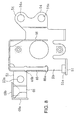
- Figure 8 is a plan view of the electrical device mounting stay 26.
- a front extension 53 which protrudes from the front right side of the main body 50 and connects to the relay holder 48, has an insertion hole 53a which is used for bolting to the boss 27 of the crankcase 15.
- the paired front and rear inserts 46 of the capacitor holder 47 are structurally the same as the inserts 48a and 48b, where they each have engaging projections 46a and 46c on the left and right sides and are inserted into the corresponding slits 45a of the heat-insulating rubbers 45 of the first and second capacitors 25a and 25b for engagement.
- FIG. 9 explains the functions of the regulator 24, the capacitor 25a and so on.
- the regulator 24 is used to rectify the alternate current generated by the AC generator 30 and, at the same time, regulate the voltage to prevent a voltage rise above a specific level.
- alternate current as shown in A is full-wave rectified as shown in B and further cut to a specific voltage level (for example, 14.5 V) as shown in C. In this condition, it becomes pulsating incomplete direct current.
- the vertical axis represents voltage V and the horizontal axis represents time t.
- the first capacitor 25a is intended to smooth pulsating output of the regulator 24 as shown in C and the voltage is smoothed by smoothing charges and discharges in response to waveform change as shown in C so that virtually complete direct current is obtained.
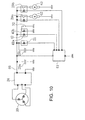
- Figure 10 is a circuit diagram of the power supply circuit for electrical devices.
- the regulator 24 is connected between the AC generator 30 and the ground. This regulator 24 rectifies the alternate current from the AC generator 30 into direct current and adjusts its voltage to a specific level and outputs it to an output line 60.
- the first capacitor 25a is connected between this output line 60 and the ground to smooth the voltage of the output line 60 and make it virtually complete alternate current.
- an ECU 61 Downstream from the point of connection of the first capacitor 25a in the output line 60, an ECU 61 is connected between it and the ground. Between the output line 60 and the ECU 61, the fuel injection system 21, ignition coil 42 and relays 29a and 29b are connected and their operations are controlled by the ECU 61.
- the second capacitor 25b is connected between a point between the fuel injection system 21 and output line 60, and the ground.
- the second capacitor 25b is charged through the output line 60 when the fuel injection system 21 is off; and when it is turned on by the EDU 61, the second capacitor 25b is discharged to supply driving power to the fuel injection system 21 and the fuel injection system 21, electromagnetically driven, injects a measured volume of fuel into the air intake duct.
- the ignition coil 42 energizes a primary coil 42a through the ECU 61. High voltage is generated in a secondary coil 42b and this is applied to the ignition plug 32 to induce spark ignition.
- the output line 60 energizes a fuel pump 62 to drive it so that fuel is pressure-fed from the fuel tank 6 to the fuel injection system 21.
- the output line 60 energizes a cooling fan 14a of a radiator 14 to drive it to raise the cooling efficiency of the radiator 14.
- the alternate current generated by the AC generator 30 is sent through the cable 31 to the regulator 24 where it becomes a direct current with a given voltage in the form of a pulsating flow.
- This incomplete pulsating direct current is smoothed by the first and second capacitors 25a and 25b and becomes an almost complete direct current.
- the first capacitor 25a supplies power to electrical devices other than the fuel injection system 21 while the second capacitor 25b supplies power only to the fuel injection system 21. Therefore, a batteryless power supply circuit is constituted in which the power generated by the AC generator 30 is directly used for power supply without a battery.
- the regulator 24 Since the regulator 24 is held behind the cylinder 16 and on the top surface of the crankcase 15, the cable 31a from the AC generator 30 (incorporated in the front part of the crankcase 15) to the regulator 24 is shortened and power loss is reduced. In addition, since the regulator 24 lies on the top surface of the crankcase 15, the vehicle's center of gravity is low and mass concentration is achieved. Moreover, the front of the regulator 24 in the traveling direction is covered by the cylinder 16 and the crankcase 15 and its lower part is covered by the crankcase 15, so the regulator is effectively protected from scattering stones.
- the cables 31b and 31c from the regulator 24 to the first and second capacitors 25a and 25b are shortened and power loss is reduced.
- first and second capacitors are mounted on the capacitor holder 47 of the electrical device mounting stay 26 held in a heat-insulating manner through the heat-insulating rubber 45, heating of these first and second capacitors 25a and 25b due to thermal conduction from the engine 10 and regulator 24 is prevented.
- first and second capacitors 25a and 25b are mounted simply by inserting the tongue-shaped inserts 46 into the slits 45a of the heat-insulating rubbers 45, their installation is easy and quick. Also, since the engaging projections 46a and 46b are provided, their engagement with the heat-insulating rubbers 45 permits reliable installation.
- the fuel injection system 21 is fitted to the throttle body 20 which extends behind the cylinder head 17 and constitutes an engine air intake system and fuel is injected by electromagnetic drive of this fuel injection system 21 using power supplied exclusively from the second capacitor 25b, the cable 34 from the second capacitor 25b to the fuel injection system 21 is shortened, and power loss is reduced. Therefore, the fuel injection system 21 is driven stably and startability of the engine 10 and drivability of the vehicle can be improved.
- first and second capacitors 25a and 25b are located above the regulator 24 inclined downward toward the rear of the vehicle body and behind and below the throttle body 20 which is relatively large in the air intake system, they can be easily mounted even if they are large-capacity large-size capacitors. Therefore, even when the batteryless type is adopted, layout for the first and second capacitors 25a and 25b is easy. Also, because the regulator 24 is inclined backward, latitude is wide in the arrangement of the connecting tube 23 connected through a space above the regulator 24 to the upstream of the throttle body 20.
- the second capacitor 25b is provided as an exclusive capacitor for the fuel injection system 21, the fuel injection system 21 is driven more stably and the engine's startability and the vehicle's drivability can be improved. Also, since the capacitor is divided into the second capacitor 25b for the fuel injection system and the first capacitor 25a for other electrical devices, the size of each capacitor can be decreased. Besides, since one capacitor is on the front side and the other is on the back side, latitude in the layout for the engine air intake system is wide. In addition, since the second capacitor 25b for the fuel injection system is on the front side, the cable 34 for connection with the fuel injection system 21 can be shortened as far as possible.
- the present invention is not limited to the above embodiment but can be modified or applied in various forms within the scope of the invention's principles.
- the second capacitor 25b exclusively intended for the fuel injection system, can be omitted.
- the first capacitor 25a now intended for other devices, can be used for power supply to both the fuel injection system 21 and the other electrical devices.
- the heat-insulating members are not limited to heat-insulating rubbers but other known heat-insulating materials may be used instead.
- Vehicles to which the present invention can be applied are not limited to motorcycles but it may be applied to other saddle-ride type vehicles such as buggies.
Landscapes
- Engineering & Computer Science (AREA)
- Chemical & Material Sciences (AREA)
- Combustion & Propulsion (AREA)
- Mechanical Engineering (AREA)
- General Engineering & Computer Science (AREA)
- Automatic Cycles, And Cycles In General (AREA)
- Cylinder Crankcases Of Internal Combustion Engines (AREA)
- Hybrid Electric Vehicles (AREA)
Applications Claiming Priority (2)
| Application Number | Priority Date | Filing Date | Title |
|---|---|---|---|
| JP2004030847A JP4325858B2 (ja) | 2004-02-06 | 2004-02-06 | 鞍乗り車両の電装品取付構造 |
| JP2004030847 | 2004-02-06 |
Publications (3)
| Publication Number | Publication Date |
|---|---|
| EP1561925A2 true EP1561925A2 (de) | 2005-08-10 |
| EP1561925A3 EP1561925A3 (de) | 2011-08-03 |
| EP1561925B1 EP1561925B1 (de) | 2013-04-24 |
Family
ID=34675562
Family Applications (1)
| Application Number | Title | Priority Date | Filing Date |
|---|---|---|---|
| EP20050100805 Expired - Lifetime EP1561925B1 (de) | 2004-02-06 | 2005-02-04 | Zusammenbau der elektrischen Geräte eines Motorrads |
Country Status (4)
| Country | Link |
|---|---|
| EP (1) | EP1561925B1 (de) |
| JP (1) | JP4325858B2 (de) |
| ES (1) | ES2422888T3 (de) |
| PT (1) | PT1561925E (de) |
Cited By (2)
| Publication number | Priority date | Publication date | Assignee | Title |
|---|---|---|---|---|
| CN101987643A (zh) * | 2009-08-03 | 2011-03-23 | 本田技研工业株式会社 | 车辆用动力单元的辅机配置构造 |
| AU2011201129B2 (en) * | 2008-01-31 | 2012-06-14 | Honda Motor Co., Ltd. | Electrical component attachment structure for two-wheeled motor vehicle |
Families Citing this family (8)
| Publication number | Priority date | Publication date | Assignee | Title |
|---|---|---|---|---|
| JP4785581B2 (ja) | 2006-03-22 | 2011-10-05 | 本田技研工業株式会社 | 自動2輪車の電装品支持構造 |
| JP5171554B2 (ja) * | 2008-10-31 | 2013-03-27 | 本田技研工業株式会社 | 自動二輪車 |
| JP5235170B2 (ja) * | 2009-06-29 | 2013-07-10 | 本田技研工業株式会社 | 自動二輪車の電装品ユニット |
| JP5235177B2 (ja) * | 2009-07-31 | 2013-07-10 | 本田技研工業株式会社 | 自動二輪車 |
| JP5385813B2 (ja) * | 2010-02-08 | 2014-01-08 | 本田技研工業株式会社 | 鞍乗り型車両の電装品取付構造 |
| JP6437373B2 (ja) * | 2015-04-09 | 2018-12-12 | 株式会社やまびこ | 携帯式作業機 |
| JP6491043B2 (ja) * | 2015-05-29 | 2019-03-27 | 川崎重工業株式会社 | 自動二輪車の電装品取付構造 |
| JP7328837B2 (ja) * | 2019-09-06 | 2023-08-17 | カワサキモータース株式会社 | 鞍乗型車両のレギュレータ遮熱構造 |
Citations (1)
| Publication number | Priority date | Publication date | Assignee | Title |
|---|---|---|---|---|
| JPS63247181A (ja) | 1987-04-02 | 1988-10-13 | ヤマハ発動機株式会社 | 自動二輪車の電装機器取付構造 |
Family Cites Families (4)
| Publication number | Priority date | Publication date | Assignee | Title |
|---|---|---|---|---|
| JP3552498B2 (ja) * | 1997-10-31 | 2004-08-11 | スズキ株式会社 | 自動二輪車の電装品取付構造 |
| JP3836665B2 (ja) * | 2000-09-06 | 2006-10-25 | 本田技研工業株式会社 | 自動二輪車 |
| JP3867486B2 (ja) * | 2000-09-06 | 2007-01-10 | スズキ株式会社 | 自動二輪車 |
| US7588009B2 (en) * | 2003-06-23 | 2009-09-15 | Honda Motor Co., Ltd. | Layout structure of a fuel injection device in a motor cycle |
-
2004
- 2004-02-06 JP JP2004030847A patent/JP4325858B2/ja not_active Expired - Fee Related
-
2005
- 2005-02-04 PT PT05100805T patent/PT1561925E/pt unknown
- 2005-02-04 EP EP20050100805 patent/EP1561925B1/de not_active Expired - Lifetime
- 2005-02-04 ES ES05100805T patent/ES2422888T3/es not_active Expired - Lifetime
Patent Citations (1)
| Publication number | Priority date | Publication date | Assignee | Title |
|---|---|---|---|---|
| JPS63247181A (ja) | 1987-04-02 | 1988-10-13 | ヤマハ発動機株式会社 | 自動二輪車の電装機器取付構造 |
Cited By (3)
| Publication number | Priority date | Publication date | Assignee | Title |
|---|---|---|---|---|
| AU2011201129B2 (en) * | 2008-01-31 | 2012-06-14 | Honda Motor Co., Ltd. | Electrical component attachment structure for two-wheeled motor vehicle |
| CN101987643A (zh) * | 2009-08-03 | 2011-03-23 | 本田技研工业株式会社 | 车辆用动力单元的辅机配置构造 |
| CN101987643B (zh) * | 2009-08-03 | 2014-07-02 | 本田技研工业株式会社 | 车辆用动力单元的辅机配置构造 |
Also Published As
| Publication number | Publication date |
|---|---|
| PT1561925E (pt) | 2013-06-04 |
| ES2422888T3 (es) | 2013-09-16 |
| JP4325858B2 (ja) | 2009-09-02 |
| EP1561925B1 (de) | 2013-04-24 |
| JP2005219669A (ja) | 2005-08-18 |
| EP1561925A3 (de) | 2011-08-03 |
Similar Documents
| Publication | Publication Date | Title |
|---|---|---|
| JP3154637U (ja) | 鞍乗り型車両 | |
| US11014438B2 (en) | Hybrid straddle vehicle | |
| US7681551B2 (en) | Electric component support structure for motorcycle | |
| EP1561925B1 (de) | Zusammenbau der elektrischen Geräte eines Motorrads | |
| US7264073B2 (en) | Battery mounting structure for an electric vehicle, and vehicle incorporating same | |
| CA2733725C (en) | Vehicle | |
| EP2692621B1 (de) | Motorrad | |
| MXPA05001421A (es) | Un sistema de inyeccion de combustible para un vehiculo de cuatro ruedas tipo motoneta. | |
| US8707926B2 (en) | Cylinder head cover structure of miniaturized vehicle | |
| US7931109B2 (en) | Arrangement of ignition coils and coil-holding structure in a motorcycle, and motorcycle including same | |
| US9862446B2 (en) | Electrical component mounting structure for saddle-riding type vehicle | |
| US20050150706A1 (en) | Fuel injection system and related structure for a four-wheeled saddle-type vehicle | |
| US7644703B2 (en) | Fuel supply device of motorcycle | |
| US20080289892A1 (en) | Straddle-type rough-road running vehicle | |
| KR100635359B1 (ko) | 자동 이륜차의 엔진 냉각 장치 | |
| US7370717B2 (en) | Radiator device for two-wheeled motor vehicle | |
| JP7328837B2 (ja) | 鞍乗型車両のレギュレータ遮熱構造 | |
| US20060288975A1 (en) | Engine accessory layout structure for vehicle | |
| AU2010210030B2 (en) | Air cleaner apparatus | |
| JP2002220076A (ja) | 不整地走行車の冷却装置 | |
| US20200238819A1 (en) | Intake device structure of saddle riding vehicle | |
| AU2016200483B2 (en) | Fuel supply device of motorcycle | |
| JP3158165B2 (ja) | 自動二輪車 | |
| JP2007224831A (ja) | 自動2輪車用燃料供給装置 | |
| JP2006069459A (ja) | 内燃機関 |
Legal Events
| Date | Code | Title | Description |
|---|---|---|---|
| PUAI | Public reference made under article 153(3) epc to a published international application that has entered the european phase |
Free format text: ORIGINAL CODE: 0009012 |
|
| AK | Designated contracting states |
Kind code of ref document: A2 Designated state(s): AT BE BG CH CY CZ DE DK EE ES FI FR GB GR HU IE IS IT LI LT LU MC NL PL PT RO SE SI SK TR |
|
| AX | Request for extension of the european patent |
Extension state: AL BA HR LV MK YU |
|
| PUAL | Search report despatched |
Free format text: ORIGINAL CODE: 0009013 |
|
| AK | Designated contracting states |
Kind code of ref document: A3 Designated state(s): AT BE BG CH CY CZ DE DK EE ES FI FR GB GR HU IE IS IT LI LT LU MC NL PL PT RO SE SI SK TR |
|
| AX | Request for extension of the european patent |
Extension state: AL BA HR LV MK YU |
|
| RIC1 | Information provided on ipc code assigned before grant |
Ipc: F02B 63/02 20060101AFI20110628BHEP Ipc: F02B 63/04 20060101ALI20110628BHEP Ipc: F02M 35/16 20060101ALI20110628BHEP Ipc: F02M 35/10 20060101ALI20110628BHEP |
|
| 17P | Request for examination filed |
Effective date: 20120127 |
|
| AKX | Designation fees paid |
Designated state(s): DE ES FR GB IT PT |
|
| GRAP | Despatch of communication of intention to grant a patent |
Free format text: ORIGINAL CODE: EPIDOSNIGR1 |
|
| RIC1 | Information provided on ipc code assigned before grant |
Ipc: F02M 35/10 20060101ALI20121003BHEP Ipc: F02M 35/16 20060101ALI20121003BHEP Ipc: F02B 63/02 20060101AFI20121003BHEP Ipc: F02B 63/04 20060101ALI20121003BHEP |
|
| GRAS | Grant fee paid |
Free format text: ORIGINAL CODE: EPIDOSNIGR3 |
|
| GRAA | (expected) grant |
Free format text: ORIGINAL CODE: 0009210 |
|
| AK | Designated contracting states |
Kind code of ref document: B1 Designated state(s): DE ES FR GB IT PT |
|
| REG | Reference to a national code |
Ref country code: GB Ref legal event code: FG4D |
|
| REG | Reference to a national code |
Ref country code: PT Ref legal event code: SC4A Free format text: AVAILABILITY OF NATIONAL TRANSLATION Effective date: 20130527 |
|
| REG | Reference to a national code |
Ref country code: DE Ref legal event code: R096 Ref document number: 602005039220 Country of ref document: DE Effective date: 20130620 |
|
| REG | Reference to a national code |
Ref country code: ES Ref legal event code: FG2A Ref document number: 2422888 Country of ref document: ES Kind code of ref document: T3 Effective date: 20130916 |
|
| PLBE | No opposition filed within time limit |
Free format text: ORIGINAL CODE: 0009261 |
|
| STAA | Information on the status of an ep patent application or granted ep patent |
Free format text: STATUS: NO OPPOSITION FILED WITHIN TIME LIMIT |
|
| 26N | No opposition filed |
Effective date: 20140127 |
|
| REG | Reference to a national code |
Ref country code: DE Ref legal event code: R097 Ref document number: 602005039220 Country of ref document: DE Effective date: 20140127 |
|
| PGFP | Annual fee paid to national office [announced via postgrant information from national office to epo] |
Ref country code: PT Payment date: 20130527 Year of fee payment: 10 |
|
| REG | Reference to a national code |
Ref country code: DE Ref legal event code: R084 Ref document number: 602005039220 Country of ref document: DE |
|
| REG | Reference to a national code |
Ref country code: GB Ref legal event code: 746 Effective date: 20141114 |
|
| REG | Reference to a national code |
Ref country code: DE Ref legal event code: R084 Ref document number: 602005039220 Country of ref document: DE Effective date: 20141120 |
|
| REG | Reference to a national code |
Ref country code: PT Ref legal event code: MM4A Free format text: LAPSE DUE TO NON-PAYMENT OF FEES Effective date: 20150804 |
|
| PG25 | Lapsed in a contracting state [announced via postgrant information from national office to epo] |
Ref country code: PT Free format text: LAPSE BECAUSE OF NON-PAYMENT OF DUE FEES Effective date: 20150804 |
|
| REG | Reference to a national code |
Ref country code: FR Ref legal event code: PLFP Year of fee payment: 12 |
|
| REG | Reference to a national code |
Ref country code: FR Ref legal event code: PLFP Year of fee payment: 13 |
|
| REG | Reference to a national code |
Ref country code: FR Ref legal event code: PLFP Year of fee payment: 14 |
|
| PGFP | Annual fee paid to national office [announced via postgrant information from national office to epo] |
Ref country code: FR Payment date: 20181213 Year of fee payment: 15 |
|
| PGFP | Annual fee paid to national office [announced via postgrant information from national office to epo] |
Ref country code: IT Payment date: 20190221 Year of fee payment: 15 Ref country code: DE Payment date: 20190122 Year of fee payment: 15 |
|
| PGFP | Annual fee paid to national office [announced via postgrant information from national office to epo] |
Ref country code: ES Payment date: 20200302 Year of fee payment: 16 |
|
| REG | Reference to a national code |
Ref country code: DE Ref legal event code: R119 Ref document number: 602005039220 Country of ref document: DE |
|
| GBPC | Gb: european patent ceased through non-payment of renewal fee |
Effective date: 20200204 |
|
| PG25 | Lapsed in a contracting state [announced via postgrant information from national office to epo] |
Ref country code: GB Free format text: LAPSE BECAUSE OF NON-PAYMENT OF DUE FEES Effective date: 20200204 Ref country code: FR Free format text: LAPSE BECAUSE OF NON-PAYMENT OF DUE FEES Effective date: 20200229 Ref country code: DE Free format text: LAPSE BECAUSE OF NON-PAYMENT OF DUE FEES Effective date: 20200901 |
|
| PG25 | Lapsed in a contracting state [announced via postgrant information from national office to epo] |
Ref country code: IT Free format text: LAPSE BECAUSE OF NON-PAYMENT OF DUE FEES Effective date: 20200204 |
|
| REG | Reference to a national code |
Ref country code: ES Ref legal event code: FD2A Effective date: 20220504 |
|
| PG25 | Lapsed in a contracting state [announced via postgrant information from national office to epo] |
Ref country code: ES Free format text: LAPSE BECAUSE OF NON-PAYMENT OF DUE FEES Effective date: 20210205 |